

Hyundai N300-055L, N300-150L, N300-075L, N300-110L, N300-185L Instruction Manual
...
INSTRUCTION MANUAL
RUN
VECTOR INVERTER
Global LeaderGlobal Leader
DOC. NO
HYUNDAI
INVERTER
H Y U N D A I
IN V E R T E R
Building a better future
ISO 9001 REGISTEREDISO 9001 REGISTERED
DNV Certification B.V., THE NETHERLANDS DNV Certification B.V., THE NETHERLANDS
MGMT. SYS.MGMT. SYS.
RvA CO24RvA CO24
SAFETY
For the Best Results with N300 Series inverter, read this manual and all of the warning sign
attached to the inverter carefully before installing and operating it, and follow the instructions exactly.
Keep this manual handy for your quick reference.
Definitions and Symbols
A safety instruction (message) is given with a hazard alert symbol and a signal word,
or . Each signal word has the following meaning throughout this manual.
WARNING CAUTION
This symbol means hazardous high voltage. It used to call your attention to items or operations
that could be dangerous to you or other persons operating this equipment.
Read these message and follow these instructions carefully.
This is the "Safety Alert Symbol" This symbol is used to call your attention to items or operations
that could be dangerous to you or other persons operating this equipment.
Read these messages and follow these instructions carefully.
CAUTION
WARNING
CAUTION
NOTE
Indicates a potentially hazardous situation which, if not avoided, can result in serious
injury or death.
Indicates a potentially hazardous situation which, if not avoided, can result in minor to
moderate injury, or serious damage of product.
The matters described under may, if not avoided, lead to serious
results depending on the situation. Important matters are described in (as
well as ), so be sure to observe them.
Notes indicate an area or subject of special merit, emphasizing either the product's
capabilities or common errors in operation or maintenance.
CAUTION
WARNING
HAZARDOUS HIGH VOLTAGE
Motor control equipment and electronic controllers are connected to hazardous line voltages.
When servicing drives and electronic controllers, there might be exposed components with cases
or protrusions at or above line potential. Extreme care should be taken to product against shock.
Stand on an insulating pad and make it a habit to use only one hand when checking components.
Always work with another person in case an emergency occurs. Disconnect power before
checking controllers or performing maintenance. Be sure equipment is properly grounded. Wear
safety glasses whenever working on an electronic controller or rotating electrical equipment.
N300 INSTRUCTION MANUAL

PRECAUTION
CAUTION : These instructions should be read and clearly understood before working on
N300 series equipment.
NOTE : POLLUTION DEGREE2
The inverter must be used environment of the degree 2.
Typical constructions that reduce the possibility of conductive pollution are,
1) The use of an unventilated enclosure
2) The use of a filtered ventilated enclosure when the ventilation is fan forced that is, ventilation is
accomplished by one more blowers within the enclosure that provide a positive intake and
exhaust.
WARNING : This is equipment should be installed, adjusted and serviced by qualified electrical
maintenance personal familiar with the construction and operation of the equipment and the hazards
involved. Failure to observe this precaution could results in bodily injury.
WARNING :The user is responsible for ensuring that all driven machinery, drive train mechanism not
supplied by HYUNDAI and process line material are capable of safe operation at an applied frequency
of 150% of the maximum selected frequency range to the AC motor. Failure to do so can result in
destruction of equipment and injury to personnel should a single point failure occur.
WARNING : For protection, install an earth leakage breaker with a high frequency circuit capable of
large currents to avoid an unnecessary operation. The ground fault protection circuit is not designed
to protect personal injury.
WARNING : Hazard of electrical shock. Disconnect incoming power before working on this control.
WARNING : Separate motor overcurrent, overload and overheating protection is required to be
provided in accordance with the safety codes required by jurisdictional authorities.
CAUTION : Proper grounds, disconnecting devices and other safety devices and their
location are the responsibility of the user and are not provided by HYUNDAI.
CAUTION : Be sure to connect a motor thermal switch or overload devices to the N300
series controller to assure that inverter will shut down in the event of an overload or an
overheated motor.
CAUTION : Dangerous voltage exists until charge lamp is off.
CAUTION : Rotating shafts and above ground electrical potentials can be hazardous.
Therefore, it is strongly recommended that all electrical work conform to the National
Electrical Codes and local regulations. Only qualified personnel should perform installation,
alignment and maintenance. Factory recommended test procedures, included in the
instruction manual, should be followed. Always disconnect electrical power before working
on the unit.
N300 INSTRUCTION MANUAL
Cautions for EMC (Electromagnetic Compatibility)
To safety the EMC directive and to comply with standard, follows the checklist below.
WARNING
This equipment should be installed, adjusted, and serviced by qualified personal familiar with
construction and operation of the equipment and the hazards involved. Failure to observe
this precaution could result in bodily injury.
1. The power supply to N300 inverter must meet these specifications
a. Voltage fluctuation 10% or less.
b. Voltage imbalance 3% or less.
c. Frequency variation 4% or less.
d. Voltage distortion THD = 10% or less.
2. Installation measure :
a. Use a filter designed for N300 inverter
3. Wiring
a. Shielded wire (screened cable) is required for motor wiring, and the length must be less
than 20 meters.
b. The carrier frequency setting must be less than 5kHz to satisfy EMC requirements.
c. Separate the main circuit from the signal/process circuit wiring.
d. In case of remote operating with connector cable, the inverter does not conform to EMC.
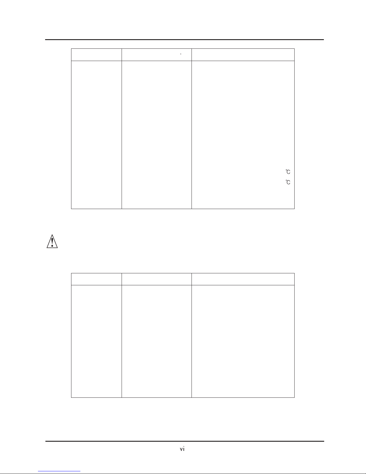
4. Environmental conditions - when using a filter, follow these guidelines:
a. Ambient air temperature : -10 - +50 .
b. Humidity : 20 to 90% RH(non-condensing)
c. Vibration : 5.9 m/sec (0.6 G) 10 - 55Hz ( N300- 055 - 220LF / 055 - 220HF)
2.94
2
m/sec (0.6 G) 10 - 55Hz ( N300- 300 - 550LF / 300 - 1320HF)
d. Location : 1000meters of less altitude, indoors (no corrosive gas or dust)
2
N300 INSTRUCTION MANUAL
Conformity to the Low Voltage Directive (LVD)
The protective enclosure must conform to the Low Voltage Directive.
The inverter can conform to the LVD by mounting into a cabinet or by adding covers as follows.
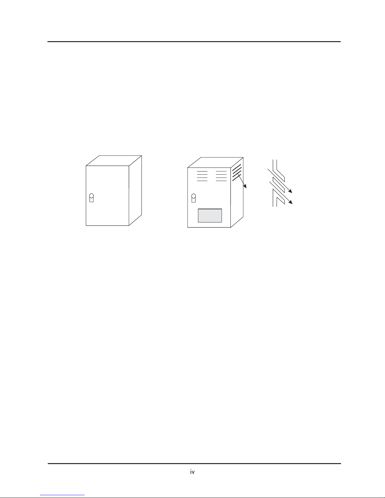
1. Cabinet and Cover
The inverter must be installed into a cabinet which has the protection degree of Type IP2X.
In addition the top surfaces of cabinet are easily accessible shall meet at least the requirements of
the protective Type IP4X, or which is constructed to prevent small objects from entering inverter.
IP4X cabinet
IP20 with louver
Fig. Inverter cabinet
Air
Air
N300 INSTRUCTION MANUAL

UL Warnings and Cautions Manual for N300 series
This auxiliary instruction manual should be delivered to the end user.
1. Wiring warnings for Electrical Practices and Wire Specifications
2. Tightening Torque and Wire Range
WARNING :
WARNING :
"Use 60/75 CU wire only" or equivalent.
"Open Type Equipment."
For models with N300 750-1320H
WARNING :
WARNING :
"Suitable for use on a circuit capable or delivering not more than 10,000 rms
symmetrical amperes, 240V maximum. "For models with suffix L.
"Suitable for use on a circuit capable or delivering not more than 10,000 rms
symmetrical amperes, 480 V maximum." For models with suffix H.
WARNING : Tightening torque and wire range for field wiring terminals are marked adjacent to
the terminal or on the wiring diagram.
8
6
4
2
1
1/0
2/0
3/0 or 2 parallel of 1 AWG
250kcmil or 2 parallel of 1 AWG
350kcmil or 2 paralleI of 1/0 AWG
(75 )
Model Name
Tightening Torque [N m]
Wire Range(AWG)
N300-055L
N300-075L
N300-110L
N300-150L
N300-185L
N300-220L
N300-300L
N300-370L
N300-450L
N300-550L
2.5
2.5
4.9
4.9
4.9
8.8
8.8
8.8
13.7
13.7
N300 INSTRUCTION MANUAL
12
10
8
6
6
4
3
1
1
1/0
250kcmil or 2 parallel of 1 AWG(75 )
250kcmil or 2 parallel of 1 AWG(75 )
3
50kcmil or 2 parallel of 1/0 AWG
2 parallel of 2/0 AWG
Model Name
Tightening Torque [N m]
Wire Range(AWG)
N300-055H
N300-075H
N300-110H
N300-150H
N300-185H
N300-220H
N300-300H
N300-370H
N300-450H
N300-550H
N300-750H
N300-900H
N300-1100H
N300-1320H
2.5
2.5
4.9
4.9
4.9
4.9
4.9
4.9
8.8
8.8
8.8
13.7
13.7
13.7
3. Circuit Breaker / Fuse Size
WARNING : Distribution fuse/circuit breaker size marking is included in the manual to indicate
that the unit shall be connected with an UL Listed inverse time circuit breaker,
rated 600V with the current ratings or an UL Listed fuse as shown in the table
below.
30
40
60
80
100
125
150
175
225
250
Model Name
Circuit Breaker [A]
Fuse [A]
N300-055L
N300-075L
N300-110L
N300-150L
N300-185L
N300-220L
N300-300L
N300-370L
N300-450L
N300-550L
30
40
60
80
100
125
150
175
225
250
N300 INSTRUCTION MANUAL
15
20
30
40
50
60
70
90
125
125
175
200
250
300
Model Name
N300-055H
N300-075H
N300-110H
N300-150H
N300-185H
N300-220H
N300-300H
N300-370H
N300-450H
N300-550H
N300-750H
N300-900H
N300-1100H
N300-1320H
15
20
30
40
50
60
70
90
125
125
-
-
-
-
4. Others
WARNING : "Field wiring connection must be made by an UL Listed and CSA Certified closed-
loop terminal connector sized for the wire gauge involved.
Connector must be fixed using the crimp tool specified by the connector manufacturer.", or equivalent wording included in the manual.
Circuit Breaker [A]
Fuse [A]
N300 INSTRUCTION MANUAL

Revision History Table
No
Revision Contents
TheDateoflssue
Operation Manual
Number
1
Initial Release of Manual NEJ 30204A
Apr. 2002
NEJ30204A
N300 INSTRUCTION MANUAL
2
Manual Cover Contents Modification
Oct. 2002
HHIS-WZ-PE-005(02)
3
Parameter Initial Value Modification
Apr. 2004
HHIS-WZ-PE-005(03)
SAFETY PRECAUTIONS
1. Installation
CAUTION
Be sure to install the unit on flame resistant material such as metal
Otherwise, there is a danger of fire.
Be sure not to place anything inflammable in the vicinity.
Otherwise, there is a danger of fire.
Do not carry unit by top cover, always carry by supporting base of unit.
There is a risk of falling and injury.
Be sure not to let the foreign matter enter such as cut wire refuse, spatter
from welding, iron refuse, wire, dust, etc.
Otherwise, there is a danger of fire.
Be sure to install it in a place which can bear the weight according to the
specifications in the text. (Chapter 6. Specifications)
Otherwise, it may fall and there is a danger of injury.
Be sure to install the unit on a perpendicular wall which is not subject to
vibration
Otherwise, it may fall and there is a danger of injury.
Be sure not to install and operate an inverter which is damaged or parts of
which are missing
Otherwise, there is a danger of injury.
Be sure install it in a room which is not exposed to direct sunlight and is
well ventilated. Avoid environments which tend to be high in temperature,
high in humidity or to have dew condensation, as well as places with dust,
corrosive gas, explosive gas, inflammable gas, grinding-fluid mist, salt
damage, etc.
Otherwise, there is a danger off fire.
P. 2 -2
P. 2 -2
P. 2 -2
P. 2 -5
P. 2 -1
P. 2 -3
P. 2 -2
P. 2 -2
N300 INSTRUCTION MANUAL

2. Wiring
WARNING
Be sure to ground the unit.
Otherwise, there is a danger of electric shock and/or fire.
Wiring work shall be carried out by electrical experts.
Otherwise, there is a danger of electric shock and/or fire.
Implement wiring after checking that the power supply is off.
It might incur electric shock and/of fire.
After installing the main body, carry out wiring.
Otherwise, there is a danger of electric shock and/or injury.
Do not remove the rubber bush. (5.5 to 55kW)
Due to the possibility that a wire may be damaged, shorted or may have
a ground fault with the edge of the wiring cover.
P.2-9
P.2-6
P.2-8
P.2-5
P.2-4
CAUTION
Make sure that the input voltage is:
Three phase 200 to 240V 50/60Hz(for models with suffix L)
Three phase 380 to 480V 50/60Hz(for models with suffix H)
Be sure not to input a single phase.
Otherwise, there is a danger of fire.
Be sure not connect AC power supply to the output terminals(U, V, W).
Otherwise, there is a danger of injury and/or fire.
Be sure not to connect the resistor to DC terminals(PD, P and N) directly.
Otherwise, there is a danger of fire.
Be sure to set the earth leakage breaker or the fuse(s)(the same phase as
the main power supply) in the operation circuit.
Otherwise, there is a danger of fire.
As for motor leads, earth leakage breakers and electromagnetic contactors,
be sure to use the equivalent ones with the specified capacity(rated).
Otherwise, there is a danger of fire.
Do not stop operation by switching off the electromagnetic contactors on the
primary or secondary sides of the inverter.
Otherwise, there is a danger of injury and/or machine breakage.
Fasten the screws with the specified fastening torque. Check so that there
is no loosening of screws.
Otherwise, there is a danger of fire.
P.2-6
P.2-8
P.2-5
P.2-5
P.2-12
P.2-12
P.2-6
P.2-12
N300 INSTRUCTION MANUAL
SAFETY PRECAUTIONS
WARNING
While the inverter is energized, be sure not to touch the main terminal or to
check the signal or put on/off wire and/or connector.
Otherwise, there is a danger of electric shock.
Be sure to turn on the input power supply after closing the front case.
While being energized, be sure not to open the front case.
Otherwise, there is a danger of electric shock.
Be sure not to operate the switches with wet hands.
Otherwise, there is a danger of electric shock.
While the inverter is energized, be sure not to touch the inverter terminals
even during stoppage.
Otherwise, there is a danger of electric shock.
If the retry mode is selected, it may suddenly restart during the trip stop. Be
sure not to approach the machine. (Be sure to design the machine so that
personnel safety will be secured even if it restarts.)
Otherwise, there is a danger of injury.
Be sure not to select retry mode for up and down equipment or traveling
equipment, because there is output free-running mode in term of retry.
Otherwise, there is a danger of injury and/or machine breakage.
Even if the power supply is cut for a short period of time, it may restart
operation after the power supply is recovered if the operation command is
given. If it may incur danger to personnel, be sure to make a circuit so that it
will not restart after power recovery.
Otherwise, there is a danger of injury.
The stop key is effective only when the function is set. Be sure to prepare
the key separately from the emergency stop.
Otherwise, there is a danger of injury.
After the operation command is given, if the alarm reset is conducted, it will
restart suddenly. Be sure to set the alarm reset after checking the operation
command is off.
Otherwise, there is a danger of injury.
Be sure not to touch the inside of the energized inverter or to put a bar into it.
Otherwise, there is a danger of electric shock and/or fire.
P. 3 -1
P. 3 -1
P. 3 -1
P. 3 -1
P. 3 -1
P. 3 -1
P. 3 -1
P. 3 -1
3. Control and operation
P. 3 -1
P. 3 -1
N300 INSTRUCTION MANUAL
SAFETY PRECAUTIONS
CAUTION
Cooling fin will have high temperature. Be sure not to touch them.
Otherwise, there is a danger of getting burned.
Low to high speed operation of the inverter can be easily set. Be sure to
operate it after checking the tolerance of the motor and machine.
Otherwise, there is a danger of injury.
Install external break system if needed.
Otherwise, there is a danger of injury.
If a motor is operated at a frequency higher than standard setting value
(50Hz/60Hz), be sure to check the speeds of the motor and the machine
with each manufacturer, and after getting their consent, operate them.
Otherwise, there is a danger of machine breakage.
Check the following before and during the test run.
Otherwise, there is a danger of machine breakage.
Was the direction of the motor correct?
Was the inverter tripped during acceleration or deceleration?
Were the rpm and frequency motor correct?
Were there any abnormal motor vibrations or noise?
P. 3 -2
P. 3 -2
P. 3 -2
P. 3 -2
P. 3 -2
WARNING
WARNING
After a lapse of more than 10 minutes after turning off the input power
supply, perform the maintenance and inspection.
Otherwise, there is a danger of electric shock.
Make sure that only qualified persons will perform maintenance, inspection
and part replacement. (Before starting the work, remove metallic objects
from your person(wristwatch, bracelet, etc.)
(Be sure to use tools protected with insulation)
Otherwise, there is a danger of electric shock and/or injury.
Never modify the unit.
Otherwise, there is a danger of electric shock and/or injury.
P. 5 -1
P. 5 -1
4. Maintenance, inspection and part replacement
5. Others
N300 INSTRUCTION MANUAL
SAFETY PRECAUTIONS

Table of Contents
TABLE OF CONTENTS
Chapter 1 General Descriptions
1.1 Inspection upon Unpacking
1.2 Question and Warranty of the Unit
1.3 Appearance
Inspection of the unit
Instruction manual
Request upon asking
Warranty for the unit
Appearance and Names of parts
Chapter 2 Installation and Wiring
Chapter 3 Operation
Chapter 4 Explanation of Function
2.1 Installation
2.2 Wiring
3.1 Operation
3.2 Test Run
4.1 About Digital Operator (OPE-S)
4.2 Code list
4.3 Explanation of function
2.1.1 Installation
2.1.2 Blind cover of wiring parts
2.2.1 Terminal Connection Diagram
2.2.2 Main circuit wiring
2.2.3 Terminal Connection Diagram
2.2.4 Digital operator wiring
4.3.1 Monitor mode
Output frequency monitor, Output current monitor, Operation direction monitor,
PID feedback monitor
Intelligent input monitor, Intelligent output monitor
Frequency conversion monitor, Output torque monitor, Output voltage monitor,
Input electric power monitor
Accumulated time monitor on Run, Power ON time monitor, Trip time monitor,
Trip monitor
N300 INSTRUCTION MANUAL

Table of Contents
4.3.2 Function mode
Output frequency setting, Operation direction, Selection with limits of operation direction,
Frequency command selection
Operation command selection, Selection no stop, Selection of stop key
Adjustable time
Base frequency
Maximum frequency, Carrier frequency
External analog input (0, 02, 01)
Input frequency Start / End
Setting analog input filter, Output voltage gain
Control system (V/f Characteristic)
Torque boost
Direct current braking (DB)
Frequency limiter
Frequency jump function, Acceleration stop function
PID function
Automatic energy-saving operation function
Two-stage acceleration and deceleration on function (2CH)
Acceleration and deceleration pattern
Instantaneous power failure / under-voltage
Open phase protection function selection, Electronic thermal function
Overload restriction / Overload advance notice
Start frequency, Reduced voltage start selection
BRD (Dynamic breaking) function, Cooling fan operating selection
Intelligent input terminal setting
Input terminal a/b (NO / NC) selection, Multi-speed operation function
Jogging operation (JG)
Second / Third control function (SET, SET3)
Software lock mode selection (SFT), Force operation ope function (OPE)
Free-run stop (FRS)
Commercial power source switching (CS)
Reset (RS)
Unattended start protection (USP), UP / DOWN selection (UP, DWN, UDC)
External trip (EXT), 3 wire input function (STA, STP, F/R)
Control gain switch function (CAS), P/PI switching function (PPI)
Intelligent output terminal setting
Intelligent output terminal a/b (NO / NC) selection
Signal during run (RUN), Frequency arrival signal (FA1, FA2, FA3, FA4, FA5)
N300 INSTRUCTION MANUAL

4.4 Protection function list
5.1 Precaution for Maintenance / Inspection
5.2 Daily inspection and regular inspection
5.3 Megger test
5.4 Withstand Voltage test
5.5 The method to check Inverter, converter part
5.6 Capacitor Life Curve
6.1 Standard specification list
6.2 Dimension
RUN time / power ON time over (RNT / ONT), Zero speed signal (ZS)
Over torque (OTQ), Alarm code output (AC0 - AC3)
FM terminal
AM terminal, AMI terminal, External thermistor
Initialization setting
Display selection
Stabilized factor, Motor constant
Fuzzy most suitable acceleration and deceleration
Braking control function
Stopping of deceleration at power off
Offline autotuning function
Motor constant selection
Online autotuning function
Sensorless vector control
0 Hz domain sensorless vector control
Torque monitor function
Torque limit function
Torque LADSTOP function
Communication function
4.4.1 Protection function
4.4.2 Trip monitor display
4.4.3 Warning Monitor display
5.1.1 Daily inspection
5.1.2 Cleaning
5.1.3 Regular inspection
Chapter 5 Maintenance, Inspection
Chapter 6 Specification
N300 INSTRUCTION MANUAL
Table of Contents

Chapter 1 General Descriptions
1.1 Inspection upon Unpacking
1.1.1 Inspection of the nuit
Open the package and pick out the inverter, please check the following item.
If you discover any unknown parts or the unit is in bad condition, please contact your supplier or the
local HYUNDAI Distributor.
(1) Make sure that there was no damage (injury, falling or dents in the body) during transportation
of the unit.
(2) After unpacking the unit, make sure that the package contains one operation manual for the
Inverter.
(3) Make sure that the product is the one you ordered by checking the specification label.
Specifications label
Model : N300-055HF
KW/(HP) : 5.5/(7.5)
Input/Entree: 50Hz, 60Hz 400 480 V 1ph A
50Hz, 60Hz 400 480 V 3ph 13A
Output
/Sortie 0.1 400Hz 3ph 12A
MFG No.
HYUNDAI
Picture 1-1 Position of specification label
Picture 1-2 Contents of specification label
Inverter model
Maximum applicable motor
Input ratings
Output ratings
Production number
1.1.2 Instruction manual
This instruction manual is the manual for the HYUNDAI Inverter N300 Series.
Before operation of the Inverter, read the manual carefully. After Reading this manual, keep it to hand
for future reference.
When using optional units for this inverter ; please refer to the instruction manuals packed with the
optional units.
This instruction manual should be delivered to the end user.
N300 INSTRUCTION MANUAL

1.2 Question and Warranty of the Unit
1.2.1 Request upon asking
1.2.2 Warranty for the unit
If you have any questions regarding damage to the unit, unknown parts or for general enquiries
please contact your supplier or the local HYUNDAI Distributor with the following information.
(1) Inverter Model
(2) Production Number (MFG No.)
(3)Dateofpurchase
(4) Reason for Calling
Damaged part and its condition etc.
Unknown parts and their contents etc.
The warranty period of the unit is one year after the purchase date. However within the warranty
period, the warranty will be void if the fault is due to;
(1) Incorrect use as directed in this manual, or attempted repair by unauthorized personnel.
(2) Any damage sustained other than from transportation (Which should be reported immediately).
(3) Using the unit beyond the limits of the specification.
(4) Natural Disasters : Earthquakes, Lightning, etc
The warranty is for inverter only, any damage caused to other equipment by malfunction of the inverter
is not covered by the warranty.
Any examination or repair after the warranty period (one-year) is not covered. And within the warranty
period any repair and examination which results in information showing the fault was caused by any of
the items mentioned above, the repair and examination cost are not covered. If you have any questions
regarding the warranty please contact either your supplier or the local HYUNDAI Distributor.
Please refer to the back cover for a list of the local HYUNDAI Distributors.
N300 INSTRUCTION MANUAL
Chapter 1 General Descriptions
1.3 Appearance
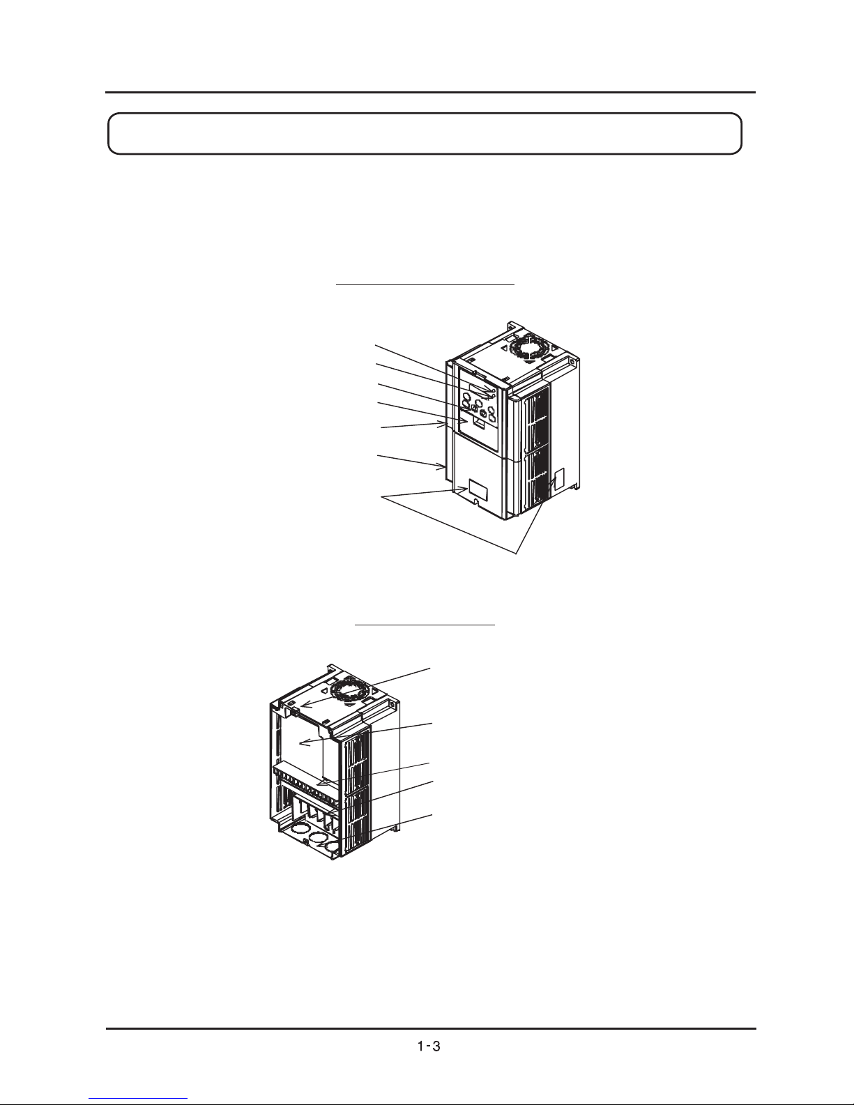
1.3.1 Appearance and Names of Parts
Appearance from the front
Front cover removed
Power lamp
Alarm lamp
Digital operator
Spacer cover
Front cover
Terminals cover
Specifications
Label
Connector
Installation point
of self-contained option
Main circuit terminals
Wiring blind cover
Control circuit terminals
(Note) When you use cable for remote operation, please remove connector.
N300 INSTRUCTION MANUAL
Chapter 1 General Descriptions
1.4 Application Method for J61 Connector Pin according to Input
Power Grounding Condition
1.4.1 Usage of J61 Connector Pin and its application
(1) Usage of J61 Connector Pin
For N300 Inverter, a protection circuit is built-in case of lightning while being used, and it can be
also protected when J61 Connector Pin is connected.
However, the Inverter can be seriously affected according to its grounding condition(grounding
or non-grounding) of input transformer.
As a result, when Inverter products are yielded, J61 Connector Pin is separately provided (open
condition). Users should choose a set of J61 Connector Pin according to the second grounding
condition of input power as the below picture after deep consideration of your field situation.
(2) Comparison according to J61 Connector Pin Using or Non-using
a) Advantage of using J61 Connector Pin
Electronic products are often damaged by lightning or thunderbolt due to its sensitivity for the
weather changing. For N300 Inverter, a protection circuit is built-in to protect the inverter from
lightning or thunderbolt by using J61 Connector Pin.
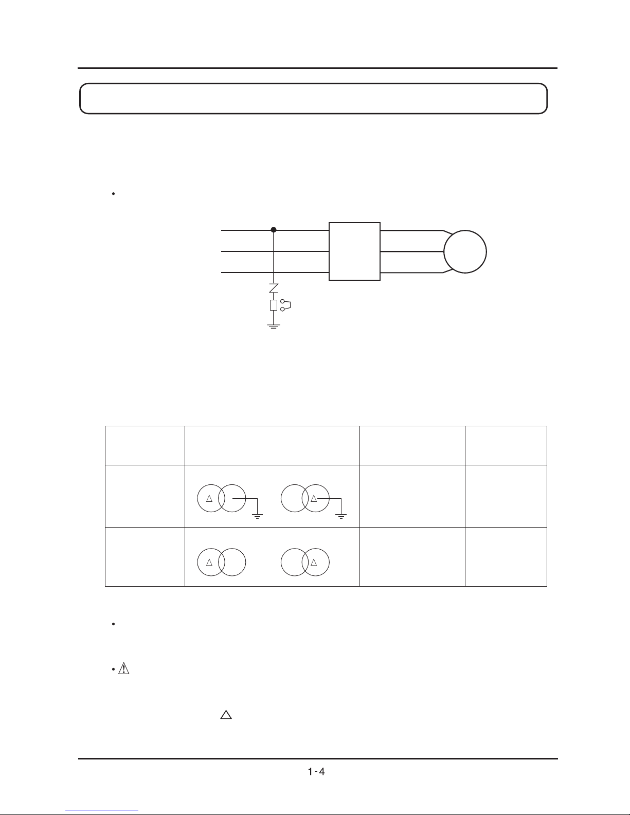
Pre-caution
You should confirm the grounding condition of power source.
When using the second inverter(inverter power input), you should confirm if Y wiring is in neutral
ground system and if wiring is in upper ground system. If you use J61 Connector Pin in
non-grounding system, Inverter can be easily damaged by excessive noise from being
expressed through ZNR .
Chapter 1 General Descriptions
Inverter
ZNR5
J61
Power input
R
S
T
Motor
U
V
W
- J61 Connector Pin Applying Condition according to grounding -
Grounding
condition
Wiring Diagram of Input
Applying Condition
of J61 Connector
Pin
Remarks
See Application
Method of
Connector in
Chapter 1.4.2
Available for J61
Connector Pin
Running open of J61
Connector Pin
(not connected)
Y Y
First Second
Or
Y Y
Or
Non-grounding
Grounding
Original
Product
First Second
First Second First Second
N300 INSTRUCTION MANUAL

b) Features of Non-using J61 Connector Pin
Although any transformer products are not grounded, there is little damage of Inverter due to no
corruption in ZNR, as noise is intercepted from electric panel.
Attention
It is not protected from the whether changing such as lightning.
c) Inquiry about J61 Connector
If you have any technical inquires about grounding and J61 Connector, please contact our
company.
1.4.2. Application of Connector Pin
(1) Location of J61 Connector Pin according to N300 Inverter Capacity
a) 5.5KW ~ 11KW Inverter Capacity (the same location as 200V Supply & 400V Supply)
b) 15KW ~ 22KW Inverter Capacity (the same location as 200V Supply & 400V Supply)
Chapter 1 General Descriptions
Location of J61
Location of J61
N300 INSTRUCTION MANUAL
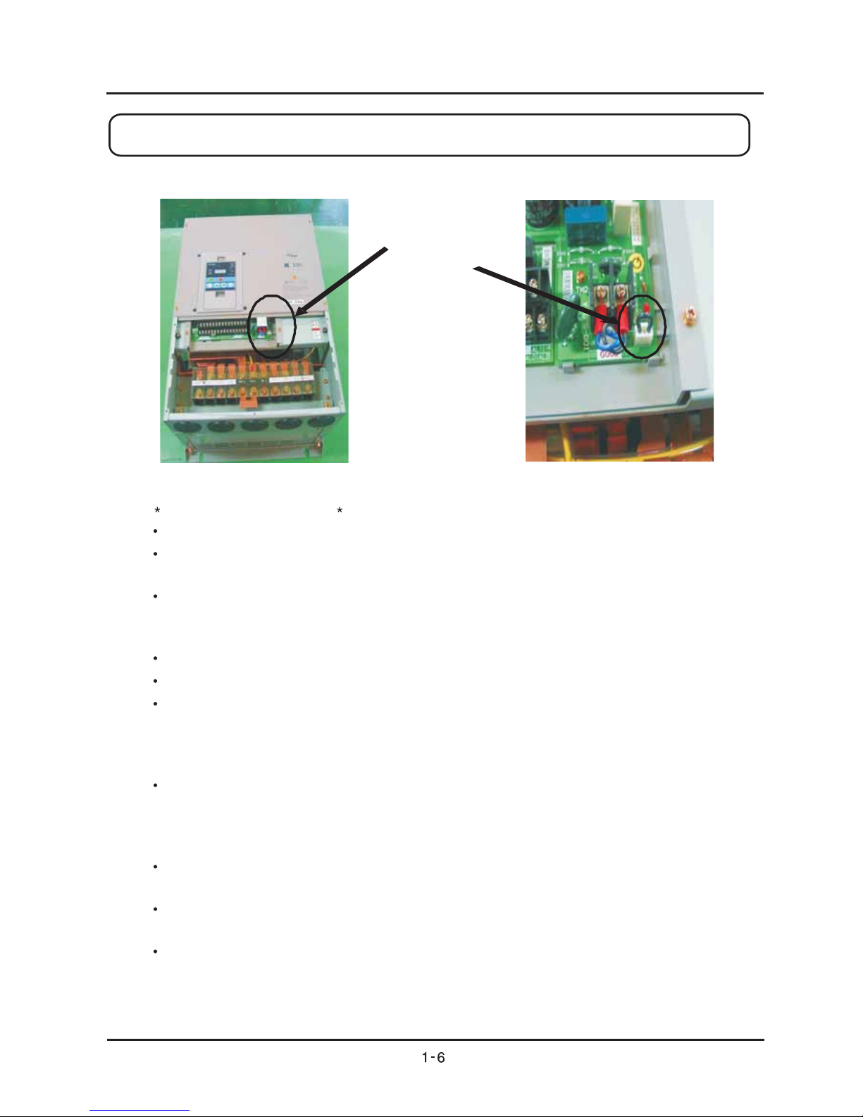
c) 30KW ~ 132KW Inverter Capacity (the same location as 200V Supply & 400V Supply)
(2) Application Method of J61 Connector
Sequencing of Application
You should turn off the power, after halting Inverter working.
You should open the Inverter cover located in the bottom level. At this very moment, you should
use Meta and confirm if DC voltage between P and N is completely discharged.
As J61 is in a different location according to Inverter capacity, you should confirm if J61 is in the
right location. For J61 Connector Pin, 5.5KW~22KW Inverter capacity is located in the bottom
right of IGBT PCB and 30KW~132KW Inverter capacity is in the bottom right of Ro-To PCB.
After checking out its location, you should connect Jump line(ending line) to J61 connector.
You should close the bottom cover after application.
You should operate the machine after turning on the Inverter power.
(3) Important items when applying J61 Connector Pin
You should decide if you use J61 Connector Pin for Inverter before applying panel.
If using J61 Connector on the purpose of protection for lightning, you should halt Inverter
working, turn off the power, and connect to it.
Also, You should apply J61 Connector pin, after checking out if DC voltage between P and N is
completely discharged by using Meta.
After application, you should turn on the power after closing the Inverter cover.
If you have any inquiries about J 61 Connector, please contact our company.
You may have an electric shock.
You may have an electric shock.
Chapter 1 General Descriptions
Location of J61
N300 INSTRUCTION MANUAL
CAUTION
Be sure to install the unit on flame resistant material such as metal.
Otherwise, there is a danger of fire.
Be sure to place anything inflammable in the vicinity.
Otherwise, there is a danger of fire.
Do not carry unit by top cover, always carry by supporting base of unit.
There is a risk of falling and injury.
Be sure not to let the foreign matter enter such as cut wire refuse, spatter from welding, iron refuse,
wire, dust, ect.
Otherwise, there is a danger of fire.
Be sure to install it in a place which can bear the weight according to the specifications in the text.
(Chapter 6. Specifications)
Otherwise, it may fall and there is a danger of injury.
Be sure to install the unit on a perpendicular wall which is not subject to vibration.
Otherwise, it may fall and there is a danger of injury.
Be sure not to install and operate an inverter which is damaged or parts of which are missing.
Otherwise, there is a danger of injury.
Be sure to install it in a room which is not exposed to direct sunlight and is well ventilated. Avoid
environments which tend to be high in temperature, high in humidity or to have dew condensation,
as well as places with dust, corrosive gas, explosive gas, inflammable gas, grinding-fluid mist, salt
damage, etc.
Otherwise, there is a danger of fire.
2.1 Installation
N300 INSTRUCTION MANUAL
Chapter 2 Installation and Wiring
Chapter 2 Installation and Wiring
2.1.1 Installation
1. Transportation
This inverter has plastic parts. So handle with care.
Do not over tighten the wall mounting fixings as the mountings may crack, causing is a risk of
falling.
Do not install or operate the inverter if there appears to be damage or parts missing.
2. Surface for Mounting of Inverter
The temperature of the Inverter heatsink can become very high (the highest being about 150 ).
The surface, which you are mounting the Inverter onto, must be made of a non-flammable material
(i.e steel) due to the possible risk of fire. Attention should also be mabe to the air gap surrounding
the Inverter. Especially when there is a heat source such as a breaking resistor or reactor.
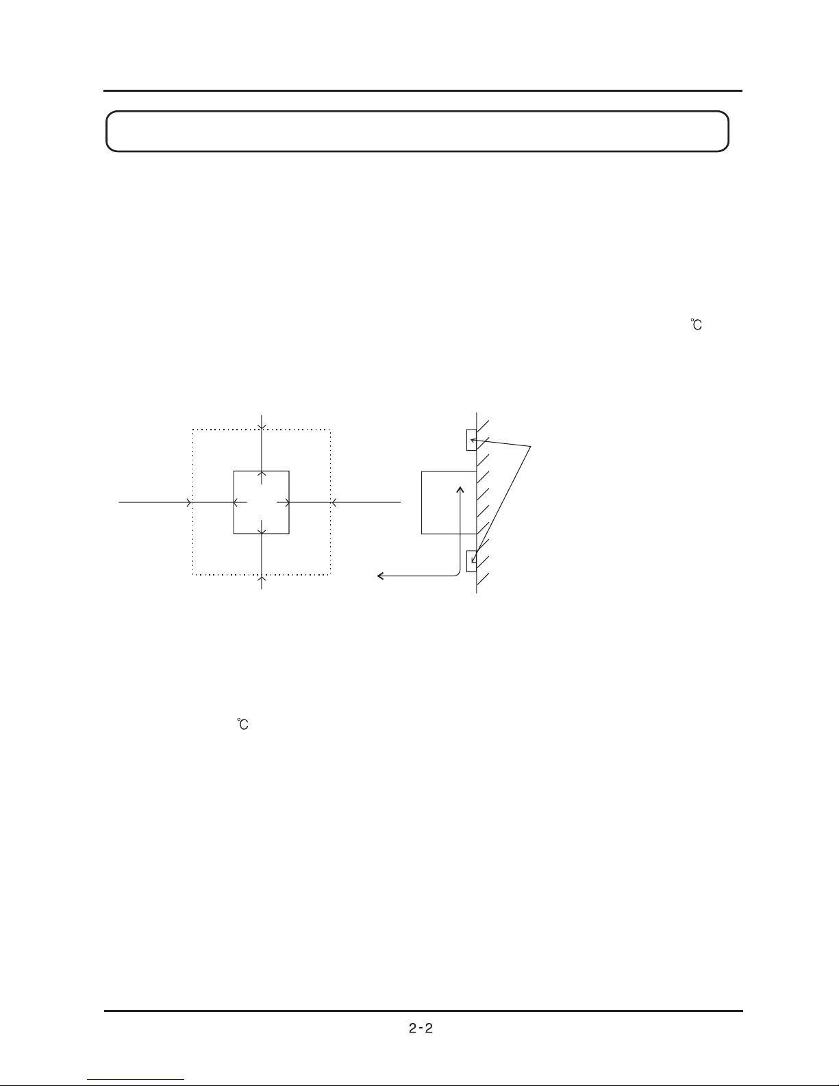
3. Operating Environment-Ambient Temperature
The ambient temperature surrounding the Inverter should not exceed the allowable temperature
range (-10 to 50 ).
The temperature should be measured in the air gap surrounding the Inverter, shown in the diagram
above. If the temperature exceeds the allowable temperature, the component life will become
shortened especially in the case of the Capacitors.
4. Operating Environment-Humidity
The humidity surrounding the Inverter should be within the limit of the allowable percentage range
(20% to 90%).
Under no circumstances should the Inverter be in an environment where there is the possibility of
moisture entering the Inverter.
Also avoid having the Inverter mounted in a place that is exposed to the direct sunlight.
5cmormore
Inverter
Inverter
(Note 2)
(Note 1)
5cmormore
Flow of the air
Wall
Keep the space enough not to be
prevented the ventilation of cooling by up
and down of wiring duct.
(Note1) 10cm or more for 0.4 to 55kW
30cm or more for 75 to 132kW
(Note2) 10cm or more for 0.4 to 55kW
30cm or more for 75 to 132kW
But for exchanging the DC bus
capacitor, take a distance.
10cmormorefor5.5to11kW
22cm or more for 15 to 55kW
30cm or more for 75 to 132kW
N300 INSTRUCTION MANUAL

5. Operating Environment-Air
Install the Inverter avoiding any place that has dust, corrosive gas, explosive gas, combustible gas,
mist of coolant and sea damage.
6. Mounting Position
Mount the Inverter in a vertical position using screws or bolts. The surface you mount onto should
also be free from vibration and can easily hold the weight of the Inverter.
7. Ventilation within an Enclosure
If you are installing one or more Inverters in an enclosure a ventilation fan should be installed.
Below is a guide to the positioning of the fan to take the airflow into consideration. The positioning
of Inverter, cooling fans and air intake is very important. If these positions are wrong, airflow around
the Inverter decreases and the temperature surrounding the Inverter will rise. So please make sure
that the temperature around is within the limit of the allowable range.
8. External cooling of Inverter
It is possible to install the inverter so that the heatsink is out of the back of the enclosure.
This method has two advantages, cooling of the inverter is greatly increased and the size of the
enclosure will be smaller.
To install it with the heatsink out of the enclosure, a metal fitting option is required to ensure heat
transfer. Do not install in a place where water oil mist flour and dust etc can come in contact
with the inverter as there are cooling fans fitted to the heatsink.
9. Approximate loss for each capacity
Ventilation fan
Ventilation fan
Inverter
Inverter
(Good example)
(Bad example)
5.5 7.5
11
15
18.5 22 30 37 45
55
75
110
132
90
242 312
435
575
698 820 1100 1345 1625
1975
2675
3900
4670
3375
325 425
600
800
975 1150 1550 1900 2300
2800
3800
5550
6650
4800
94.4 94.6
94.8
94.9
95.0 95.0 95.1 95.1 95.1
95.1
95.2
95.2
95.2
95.2
Inverter capacity(kw)
70% of rated output(w)
100% of rated output(w)
100% of rated efficiency(%)
N300 INSTRUCTION MANUAL
Chapter 2 Installation and Wiring
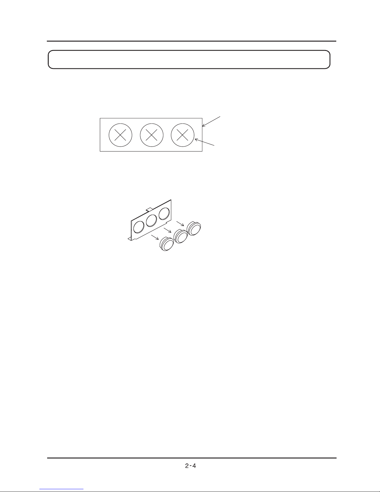
Wiring cover
Rubber bushes
2.1.2 Blind cover of wiring parts (5.5 to 55kW)
(1) Cable entry through Rubber Bushes
The wiring should be done after making a cut in the rubber bushes with nippers or cutters.
(2) Cable entry through Conduit
After taking out the rubber bushes, connect the conduit.
(Note) Except for when connecting conduit, do not take out the rubber bushes. It is possible that the
wiring insulation is broken and a possible earth fault is caused.
N300 INSTRUCTION MANUAL
Chapter 2 Installation and Wiring
2.2 Wiring
WARNING
Be sure to ground the unit.
Otherwise, there is a danger of electric shock and/or fire.
Wiring work shall be carried out by electrical experts.
Otherwise, there is a danger of electric shock and/or fire.
Implement wiring after checking that the power supply is off.
It might incur electric shock and/or fire.
After installing the main body, carry out wiring.
Otherwise, there is a danger of electric shock and/or injury.
Do not remove the rubber bush. (5.5 to 55kW)
Due to the possibility that a wire may be damaged, shorted or may have a ground fault with the
edge of the wiring cover
CAUTION
Make sure that the input voltage is:
Three phase 200 to 240V 50/60Hz (for models with suffix L)
Three phase 380 to 480V 50/60Hz (for models with suffix H)
Be sure not to input a single phase.
Otherwise, there is a danger of fire.
Be sure not to connect AC power supply to the output terminals (U, V, W).
Otherwise, there is a danger of injury and/or fire.
Be sure not to connect the resistor to DC terminals (PD, P and N) directly.
Otherwise, there is a danger of fire.
Be sure to set the earth leakage breaker or the fuse(s) (the same phase as the main power supply)
in the operation circuit.
Otherwise, there is a danger of fire.
As for motor leads, earth leakage breakers and electromagnetic contactors, be sure to use the
equivalent ones with the specified capacity (rated).
Otherwise, there is a danger of fire.
Do not stop operation by switching off the electromagnetic contactors on the primary or secondary
sides of the inverter.
Otherwise, there is a danger of injury and/or machine breakage.
Fasten the screws with the specified fastening torque. Check so that there is no loosening of screws.
Otherwise, there is a danger of fire.
N300 INSTRUCTION MANUAL
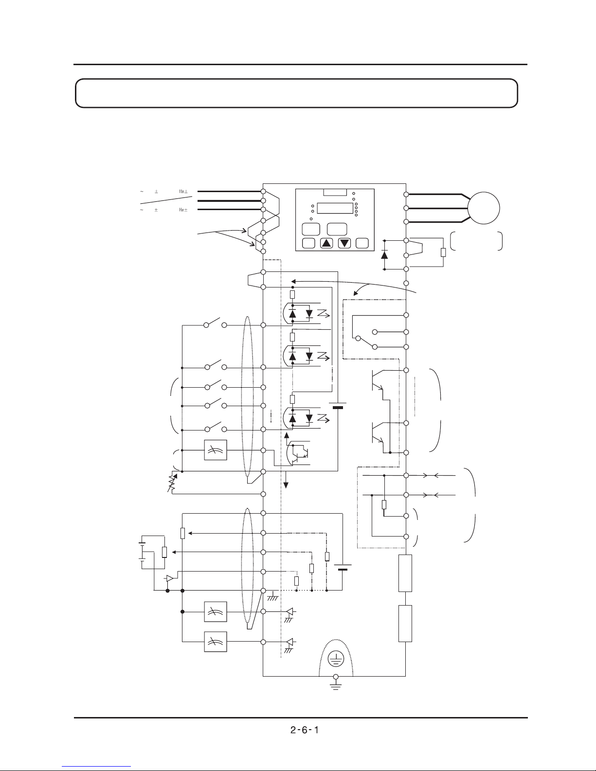
Chapter 2 Installation and Wiring
R
S
T
R
T
RO
TO
P24
PLC
FW
8
7
6
1
FM
CM1
TH
H
0
OI
L
AM
100
02
DC0-10V
HYUNDAI
POWER
ALRAM
RUN
PRG
V
A
%
RUN
STOP/RESET
FUNC
STR
1
2
U
V
W
P
PD
RB
N
IM
AL0
AL1
AL2
DC24V
DC0-10V
DC0-10V(12bit)
DC0-10/0/-10V(12bit)
DC4-20mA(12bit)
ohm
10k
0-10V(8bit)
4-20mA(8bit)
AMI
ohm
ohm
10k
15
11
CM2
SP
SN
RP
SN
RS485
200 240V 10%(50,60 5%)
380 480V 10%(50,60 5%)
8.8.8.8.
Power
Source 3phase
Short wire
Short bar
(at sink type)
Forward
Intelligent input
(8 connection)
FM output monitor
(PWM output)
AM output monitor
(Analogue output)
AMI output monitor
(Analogue output)
Thermistor
Earth
Option 2
Option 1
For terminal resistance
Intelligent output
(5 connection)
Intelligent relay output
connection
(Initial alarm)
Put and take
as terminal substrate
Shortbar
Braking resistor
(Option)
BRD circuit:
Installed on
5.5to11kW
2.2.1 Terminal Connection Diagram (sink type)
N300 INSTRUCTION MANUAL
Hz
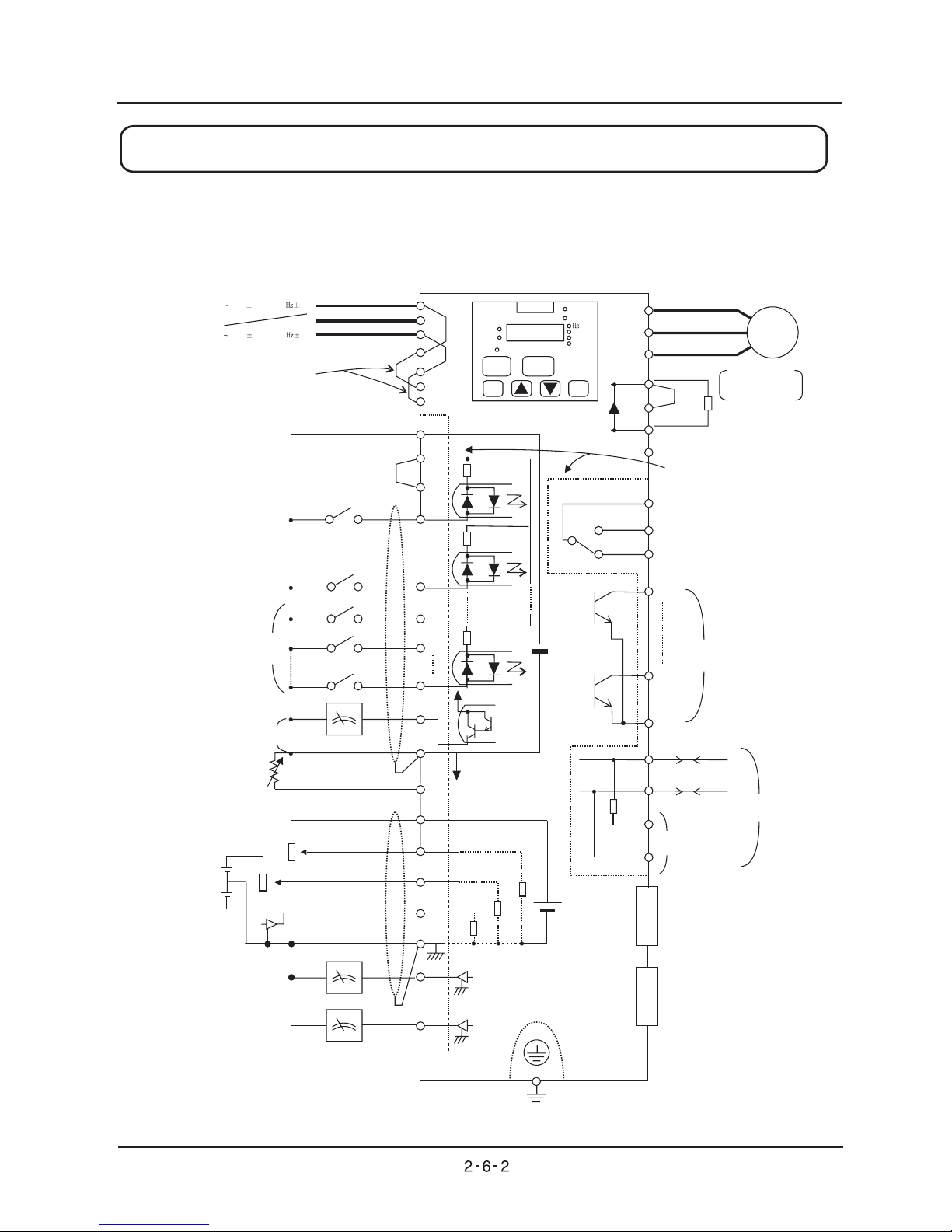
Chapter 2 Installation and Wiring
R
S
T
R
T
RO
TO
P24
PLC
FW
8
7
6
1
FM
CM1
TH
H
0
OI
L
AM
100
02
DC0-10V
HYUNDAI
POWER
ALRAM
RUN
PRG
V
A
%
RUN
STOP/RESET
FUNC
STR
1
2
U
V
W
P
PD
RB
N
IM
AL0
AL1
AL2
DC24V
DC0-10V
DC0-10V(12bit)
DC0-10/0/-10V(12bit)
DC4-20mA(12bit)
ohm
10k
0-10V(8bit)
4-20mA(8bit)
AMI
ohm
ohm
10k
15
11
CM2
SP
SN
RP
SN
RS485
200 240V 10%(50,60 5%)
380 480V 10%(50,60 5%)
8.8.8.8.
Power
Source 3phase
Short wire
Short bar
(at source type)
Forward
Intelligent input
(8 connection)
FM output monitor
(PWM output)
AM output monitor
(Analogue output)
AMI output monitor
(Analogue output)
Thermistor
Earth
Option 2
Option 1
For terminal resistance
Intelligent output
(5 connection)
Intelligent relay output
connection
(Initial alarm)
Put and take
as terminal substrate
Shortbar
Braking resistor
(Option)
BRD circuit:
Installed on
5.5to11kW
CM1
2.2.1 Terminal Connection Diagram (source type)
N300 INSTRUCTION MANUAL
Chapter 2 Installation and Wiring
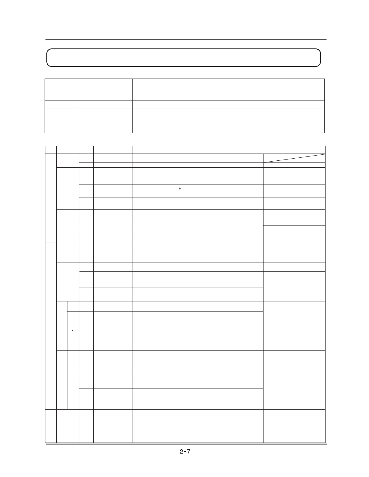
(1) Explanation of main circuit terminals
Symbol
R,S,T
(L1,L2,L3)
U, V, W
(T1,T2,T3)
PD,P
(+1,+)
P, R B
(+,RB)
P, N
(+,-)
G
Terminal Name
Main power
Inverter output
D.C reactor
External braking resistor
External Regenerative unit
Inverter earth terminals
Explanation o f contents
Connect alternating power supply.
Connect three- phase motor.
Remove the short bar between PD and P, connect optional power factor reactor(DCL)
Connect optional External braking resistor. ( Installed on 5.5kW to 11kW )
Connect optional Regenerative braking unit (BRD).
It is earth terminals of inverter case.
(2) controlExplanation of circuit terminal
Allowable minimum
AC100V,10mA
It is common terminal of frequency command signal(O, O2, OI)
and analogue output, AM, AMI. Don"t earth.
It is the DC+10V power for terminals.
When inputting DC 0 ~10V, it is maximum frequency on 10V.
When maximum frequency is expected to be on being less then 10V,
set with A014
When inputting DC 0 ~ 10V, this signal is added to frequency
command of O or OI terminal.
Output one selected from monitor item, output frequency, output
current, torque, output voltage, input electric power, electric thermal
rate, LAD frequency
Output the output frequency with digital besides above monitor.
It is DC24V power for connection input signal. When selecting source
logic, it's connection input common
The common terminal is FW terminal, 1-8 terminal, TH terminal,
FM terminal, Don't earth.
About FW signal, ON is Forward and OFF is stop command.
Select 8 function from 44 functions, and divide between 1 terminal
and 8 terminals.
Select 5 function from 22 functions, and divide between 1 terminal
and 5 terminals.
Change sink type and source type by short bar on control terminals.
P24-PLC : Sink type CM1-PLC : Source type
Analogue
Analogue
L
H
O
O2
OI
AM
AMI
FM
P24
CM1
FW
1(RS)
2(AT)
3(JG)
4(FRS)
5(2CH)
6(CF2)
7(CF1)
8(RV)
PLC
When a Thermistor connected to terminals TH and CM1, the inverter
checks for over-temperature and will cause trip event and turn off
output to motor.
11(FA1)
12(RUN)
13(OL)
14(OTQ)
15(IP)
TH
AL0
AL1
AL2
setting
operation/Function
Selection etc
Analogue power
common
Frequency power
Frequency command
support(voltage)
Frequency command
Terminal (current)
Digital monitor
(voltage)
Analogue monitor
(Current)
Digital monitor
(Voltage)
Interface power
Interface power
common
Forward command
Input intelligent
Intelligent input
common
Frequency
command power
terminal(voltage)
Allowable load current 20mA
Input Impedance 10K ohm
Allowable maximum voltage 12V
load
current 20mA
Input Impedance 10K ohm
Allowable maximum
0
4
Input Impedance 10 ohm
Allowable maximum current 2 mA
Allowable maximum current 2mA
Allowable output less then
impedance 250 ohm
1.2mAAllowable maximum current
Maximum frequency 3.6kHz
Allowable maximum output
current 100mA
Allowable maximum
voltage 27V
Input ON condition of terminal
voltage
Over 18V
Input OFF condition of terminal
voltage
under 3 V
Input impedance 4.7k ohm
Allowable maximum
voltage 27V
current 50mA
Allowable minimum
Thermistor power 100mW
Allowable minimum
AC250V, 0.2A
Cindition/Alarm
input Intelligent
Thermistor input
terminal
Alarm output
terminal
Common terminal
IInput signal
Sensor
Output signal
It is common terminal of alarm output terminal
Assign output function. Output is c contact
Explanation o f contents
Terminal Name
Digitasl(connection)
Symbol
Power
Source
Frequency
setting
When inputting DC 4 ~20mA, 20mA is maximum frequency.
When only terminal is ON, this input signals is effective.
Monitor
Power
Source
N300 INSTRUCTION MANUAL
Chapter 2 Installation and Wiring
 Loading...