

Hyundai N100 plus Instruction Manual

Technical Support
Document for Inverter
Doc. No. TSD-N100-COM-001E(00)
Model All N100 model
Rev. Date August, 2008
N100
plus
Inverter RS485 Interface
Instruction Manual

N100
plus
Inverter RS485 Interface Instruction Manual
i
Contents
1. RS485 Communication function .....................................................................................................1
1.1 Communication function........................................................................................................1
1.1.1 Interface Cable Pin Arrangement .............................................................................1
1.1.2 Interface Cable Pin Arrangement .............................................................................2
1.1.3 RS485 Communication specification ........................................................................3
1.1.4 RS485 Communication setting in Inverter................................................................3
1.1.5 Communication order................................................................................................4
1.2 Communication protocol .......................................................................................................4
1.2.1 Inverter read frame...................................................................................................5
1.2.2 Request frame for setting parameter .......................................................................6
2. Example of Transmit/Receive Data frame.................................................................................. 11
2.1 Read Request & Response Data ........................................................................................ 11
2.1.1 A prior condition .................................................................................................... 11
2.1.2 Example 1 – Output frequency Monitoring (Function code : D01) ....................... 11
2.1.3 Example 2 – Output frequency (Function code : F01).......................................... 12
2.1.4 Example 3 – Acceleration time (Function code : F02).......................................... 12
2.2 Setting Request & Response Data..................................................................................... 13
2.2.1 A prior condition .................................................................................................... 13
2.2.2 Output frequency setting (Function code : F01)................................................... 13
2.2.3 Example 4 – Acceleration time 1 setting (F02) .................................................... 13
2.2.4 Example 5 – Deceleration time 1 setting (F03) .................................................... 13
2.3 Frequency Command.......................................................................................................... 14
2.3.1 A prior condition .................................................................................................... 14
2.3.2 Example 6 – Frequency Command (In case of 60Hz)........................................... 14
2.3.3 Example 7 – Frequency Command (In case of 50Hz)........................................... 14
2.4 RUN command parameter .................................................................................................. 15
2.4.1 A prior condition .................................................................................................... 15
2.4.2 Example 8 – FWD(Forward) RUN Command......................................................... 15
2.4.3 Example 9 – REV(Reverse) RUN Command.......................................................... 15
2.4.4 Example 10 – STOP Command .............................................................................. 16
N100
plus
Inverter RS485 Interface Instruction Manual
N100_Inverter RS485 Interface Manual(English).doc 1
1. RS485 Communication function
1.1 Communication function
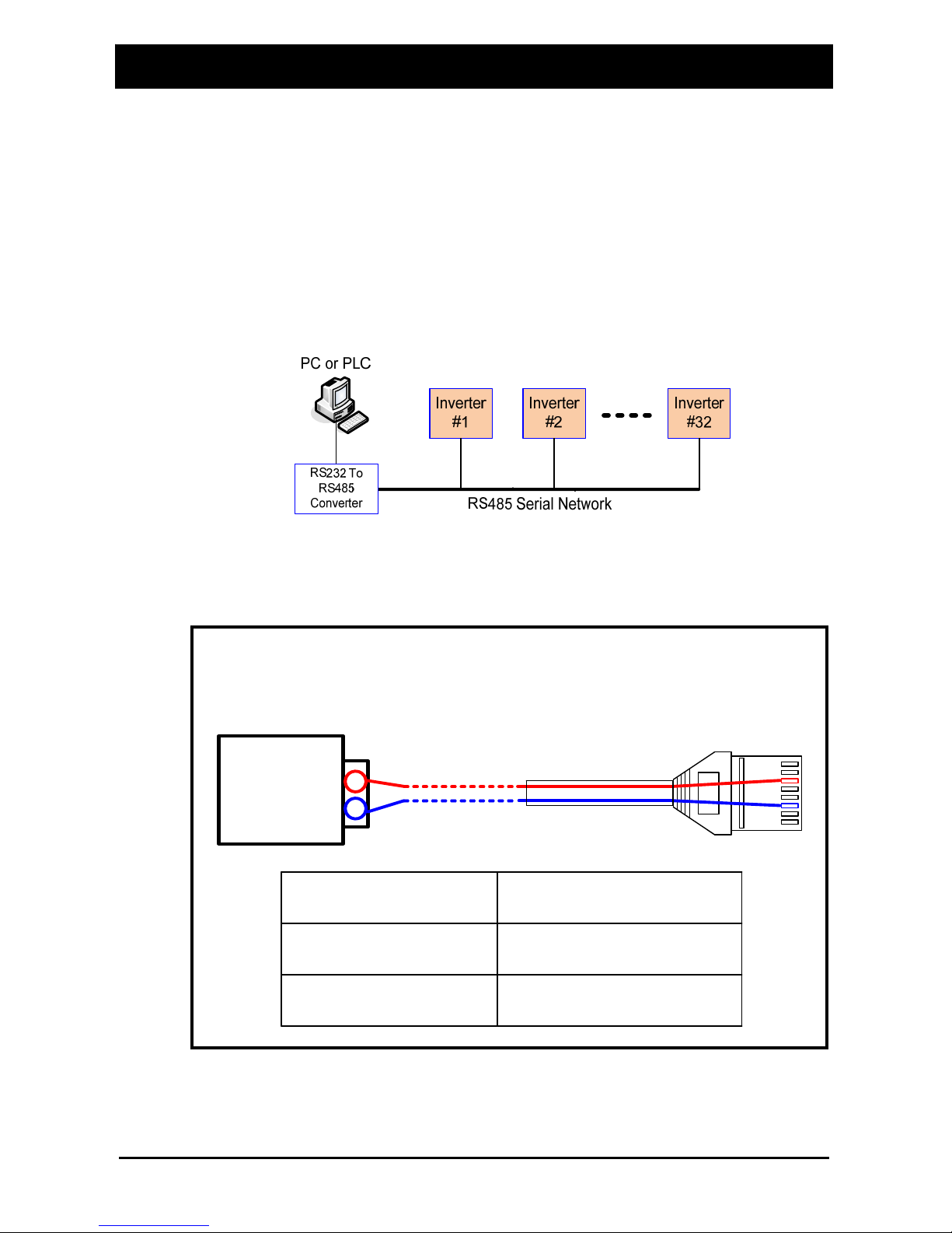
Communication circuit for RS485 is built in N100 Inverter.
It is possible to control 1~32 Inverters (Slave) from a main control device (Master) by
using RS485 serial communication is supported.
Fig. 1 RS485 Serial network
1.1.1 Interface Cable Pin Arrangement
Fig. 2 Cable Pin configuration
①
④
⑧
⑦
②
⑤
⑥
③
+
-
+
-
RS 232-485
converter
Description RJ45 Pin No.
Cable Pin configuration
TX/RX - 6
TX/RX + 3
N100
plus
Inverter RS485 Interface Instruction Manual
N100_Inverter RS485 Interface Manual(English).doc 2
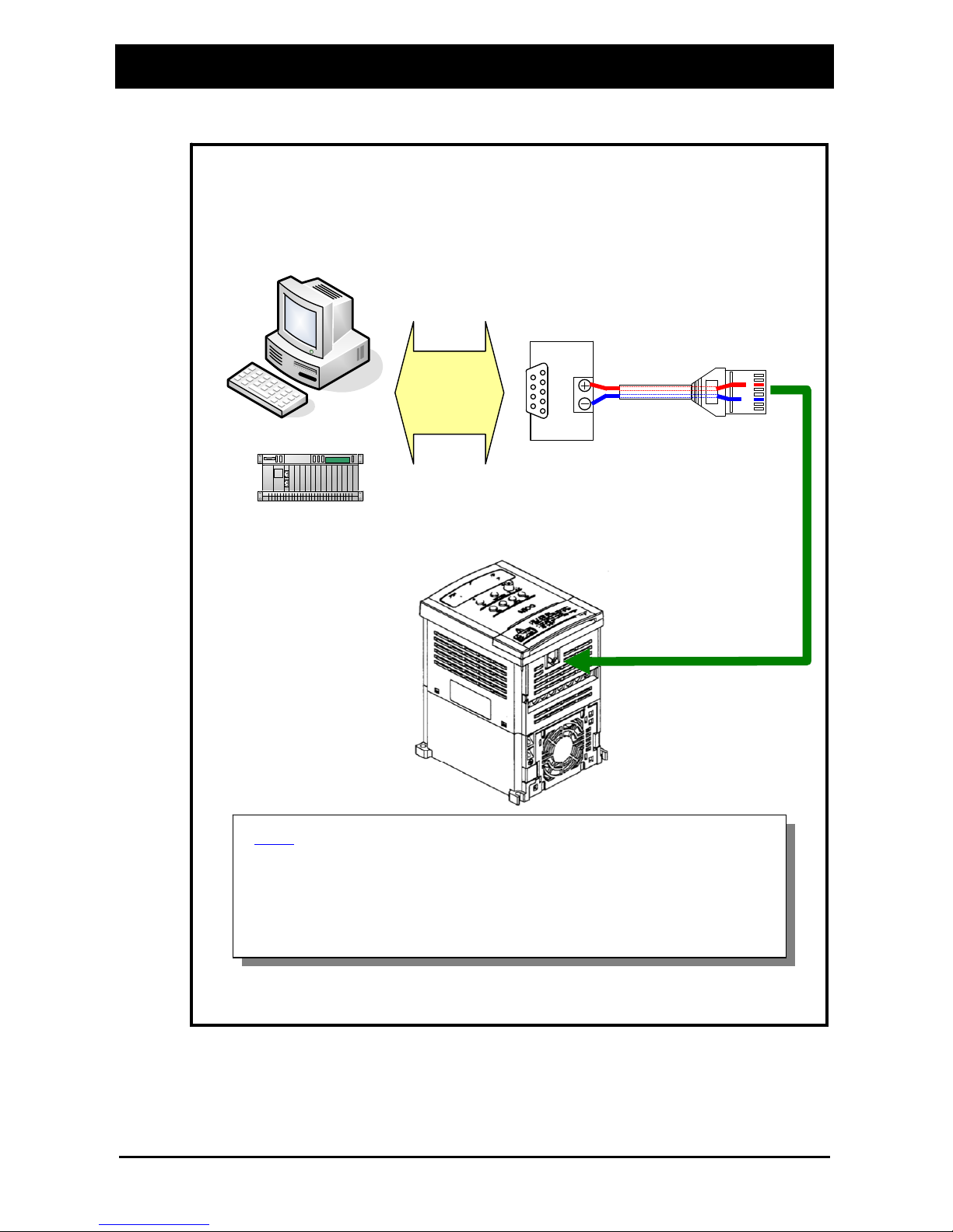
1.1.2 Interface Cable Pin Arrangement
Fig. 3 PC(or PLC) ~ Inverter Wiring Diagram
PC(or PLC) ~ Inverter Wiring Diagram
①
④
③
⑧
⑦
②
⑤
⑥
PC
PLC
RS232
RS485
RS232
To RS485
Converter
Note
If the PLCs have a RS485 communication port, don’t use the
converter (RS232 to RS485 converter) between the PLCs
and inverter.

N100
plus
Inverter RS485 Interface Instruction Manual
1.1.3 RS485 Communication specification
Item Specification Notes
Communication
interface
RS485
Communication methods Half duplex communication methods
Transmission speed
(Baud Rate)
9600[BPS]
Start methods
Response for the external read, write
command
The inverter operates only as
slave.
Transmission code Binary code
Data bit 8[bit]
Parity No parity/even/odd
Stop bit 1[bit]
Connect form 1:N (N=Maximum 32)
Main function Fleming/CRC/CMD/MAXREQ/Parameter
Table 1 RS485 Communication specification
1.1.4 RS485 Communication setting in Inverter
The following setting are required to operate RS485 communication
Function
code
Set item Initial data Data Description
b17 Communication Number 1 1
Inverter Address No. 1
(Address : 1 ~ 32)
A01
Frequency commanding
(Multi-speed
commanding method)
0 3
0 : Keypad potentiometer
1 : Control terminal input
2 : Standard operator
3 : Remote operator
(Communication)
A02 RUN commanding 0 2
0 : Standard operator
1 : Control terminal input
2 : Remote operator
(Communication)
Table 2 RS485 Communication setting
N100_Inverter RS485 Interface Manual(English).doc 3

N100
plus
Inverter RS485 Interface Instruction Manual
1.1.5 Communication order
The flow of the communication protocol between an external control device and an
inverter is shown below in the time diagram.
Fig. 4 Communication order
Devices
External control
Frame 2
(setting with operator)
Waiting time
Frame 1
Inverter
Frame start : Frame start is recognized by signal line data transmitted.
Frame completion: Frame completion is recognized by no data during correspond 4,
5-character time.
Frame 1: Transmit from external controller to inverter.
Frame 2: Indication reflects from inverter to external controller.
Frame 2 in inverter displays as the signal that inverter receiving Frame 1
and recognizes a suitable frame and responds, and don’t output actively.
1.2 Communication protocol
ModBus protocol that applies Query-Response Cycle method is used in the communication.
The communication network is controlled by the master equipment, and it is operated by
the method that the slave equipment reply from the transmission request of the master
equipment. ModBUS communication frame type and form is as follows.
N100_Inverter RS485 Interface Manual(English).doc 4
 Loading...