

Hyundai H-LED29V17 Instruction Manual
H-LED29V17
LED TV
ТЕЛЕВИЗОР
ЦВЕТНОГО ИЗОБРАЖЕНИЯ
ЖИДКОКРИСТАЛЛИЧЕСКИЙ
(LCD)
Руководство по эксплуатации Instruction manual

Table of contents
Dear customer!
Thank you for purchasing our product. For safety, it is strongly recommended to read
this manual carefully before connecting, operating and/or adjusting the product and keep
the manual for reference in the future.
Table of contents
Before you start
Utilization of the product
Important safeguards
Installation
Wall mounting
Stand installation
Connection
Connection
Outdoor antenna connection
Other connections
Operation
Control elements
Front panel
Back panel
Remote controller
Changing the battery
General operations
Teletext operations
OSD operation
Channel setting
Picture setting
Sound setting
Timer setting
Option setting
USB operation
General operatoins of file playback
General information
Troubleshooting
Causes of interference
Accessories
Specifications
2
3
3
3
4
4
4
5
5
5
5
6
6
6
6
7
7
8
8
8
9
10
10
10
10
11
11
13
13
13
14
14
2

Before you start
Utilization of the product
If you want to dispose this product, do not mix it with general household waste. There is
a separate collection system for used electronic products in accordance with legislation
that requires proper treatment, recovery and recycling.
Please contact your local authorities for the correct method of disposal. By doing so,
you will ensure that your disposed product undergoes the necessary treatment, recovery
and recycling and thus prevent potential negative effects on the environment and human
health.
Important safeguards
• Before connecting the AC power cord
to the DC adapter outlet, make sure that
the voltage designation of the DC adapter
corresponds to the local electrical supply.
• Accessories include a DC adaptor marked
with the TV model number. Do not use other
adaptors with this unit.
• Please unplug the power cord from the AC
outlet and contact a service center for repair
if following occurs: any obvious abnormality
appears in the unit, such as smoky, peculiar
smell or strange sound; liquid has been spilled or
other objects have fallen into the unit; no picture
or sound; cover or panel is broken; although you
have operated the unit following the operating
instructions, it still cannot work normally.
• This unit can be connected to a power
supply outlet without the third ground contact
as well as with a ground contact.
• Always disconnect the power cord and
antenna during a storm.
• Do not fix the power cord with a metal nail.
• Unplug the power cord from the AC outlet;
also unplug the signal cables from the input
ports when the unit is unused for long periods
of time.
• When unplugging the plug, always hold
the wide slot, do not touch the metal part, and
do not destroy, refit, twist, pull or roast the
power cord.
• Please contact the service center
immediately if you found that the core is
showed in the air or has been broken.
• Please replace the AC outlet if the metal
bolt cannot be inserted into the power socket
completely or it cannot be fastened even when
it was pushed in, otherwise, any accidents of
shocks and fires would happen.
• Never touch the antenna lie or power plug
if it stars to thunder.
• Do not touch the power plug with wet hands.
• Do not use any non-rated power socket
with numerous devices jointed on one power
socket or cable device. The wire of nondesignated capacity may cause the fire due to
the generation of heat.
• All instructions must be read and
understood well before you operate the unit.
Heed all warnings and follow all instructions.
• Please use the accessories provided
by the manufacturer. Using inadequate
accessories may result in accidents.
• Please adjust the product through the
panel buttons or the remote controller, do
not remove the cover or attempt to service
the product by yourself. Do not disassemble
back cover and do not make maintenance by
yourself to avoid the electric shock.
• Over-press the panel may destroy the
product.
• Do not place the product on an unstable
cart, stand surface, tripod, bracket, or table.
The product may fall, causing serious accidents
3

Before you start
as well as the damage to the product.
• Please place the product on a flat surface
in a well-ventilated location. Keep it away from
the burning-light, direct sunlight, vibration,
high-temperature and humidity.
• The apparatus shall not be exposed to
dripping or splashing and that no objects filled
with liquids, such as vases, shall be placed on
the apparatus.
• Do not install it at the place on the strong
magnetic field or current field. It may cause
break down. This equipment may be observed
deterioration of the picture by electromagnetic
radiation in electromagnetic environment.
• Fasten the wheel of the product or shelf
with wheels when installing this product. If it
moves or is tipped over, it may be damaged.
• Do not place any fire source such as
candlelight close to this product or place it on
this product. If it is tipped over or fallen down, it
may cause damage or fire.
• Do not place the unit into closed space
of TV for better ventilation; it can reduce the
product lifetime. Keep a space at least 10 cm
at above, left and right of the TV.
• Please place all the signal cords behind of
rear panel.
• Do not overexert or touch the panel when
you convey the product. Do not transfer the
LCD TV up or down display direction.
• Do not transport it with the power cord
connected. If you move this product with the
power cord or the connection cable connected,
the damaged power cord, connection cable
or connection terminal may cause the fire, the
electric shock or breakdown.
• 2 persons or more shall transport the
device, which is heavier than 18 kg. If you drop
or tip over the device, it can be damaged.
• The temperature of the product’s body
becomes a little higher after a long period use.
This phenomenon indicates that heat exchange
in normal working mode, thus please do not
let children or anyone who is sensitive of
temperature to touch.
All images provided herein are schematic
drawings and may differ from of real objects.
Installation
Wall mounting
For wall mounting the back panel of this
unit is equipped with 4 screw holes (4 mm
diameter, 100 mm horizontal spread distance
x 100 mm vertical spread distance). A
wall-mount bracket should be used for wall
mounting (the bracket is not included and
should be acquired separately). Manufacturer
is not responsible for improper mounting
resulting in damage of the unit.
Stand installation
Place the LED TV on a solid flat surface.
Use soft material to place over the front screen
to avoid any damage. Then put the slits of the
stand onto the fixing elements in the lower part
of the unit until a click and fix the two parts by
four screws as shown below:
4

Connection
Connection
Antenna cable connector
75 Ohm co-axis cable
Outdoor Antenna Connection
Use 75Ω coaxial cable plug or 300-75Ω
impedance converter to plug in antenna input
terminal on the rear of the cabinet.
Other connections
• Connect a TV or CATV antenna to the
antenna jack.
• Connect a video source to the Composite
video input jack with RCA cable.
• Connect an audio source to the proper
Audio input jacks (left and right).
• Connect the power cord to the DC
adaptor, then connect the adapter to the DC
power jack of this unit.
• Connect PC audio input to PC main unit
with related audio cable in PC mode.
• When using the unit as a computer screen,
connect the PC to the PC jack of the unit by
the relevant cable.
TVRF antenna jack
• If the video source has a HDMI output
jack, you can connect the signal to the unit by
HDMI cable (not included).
• Component input is intended for receiving
component video signal if connected to the
component output of external signal source. To
receive audio signal for component video, please
use Left and Right audio inputs of this unit.
• Connect an external device (e.g., VCR-/
DVD-recorder) to the proper Audio/Video
output jacks of this unit with AV RCA cable.
• Connect your headphones or earphones
(not included) to the headphone socket of this
unit. When headphones are connected, the
sound output through the built-in speakers of
this unit is mute.
• Coaxial output is intended for transmitting
multi-channel sound to an external decoder
(e.g. in 5.1-CH format).
5
Operation
Control elements
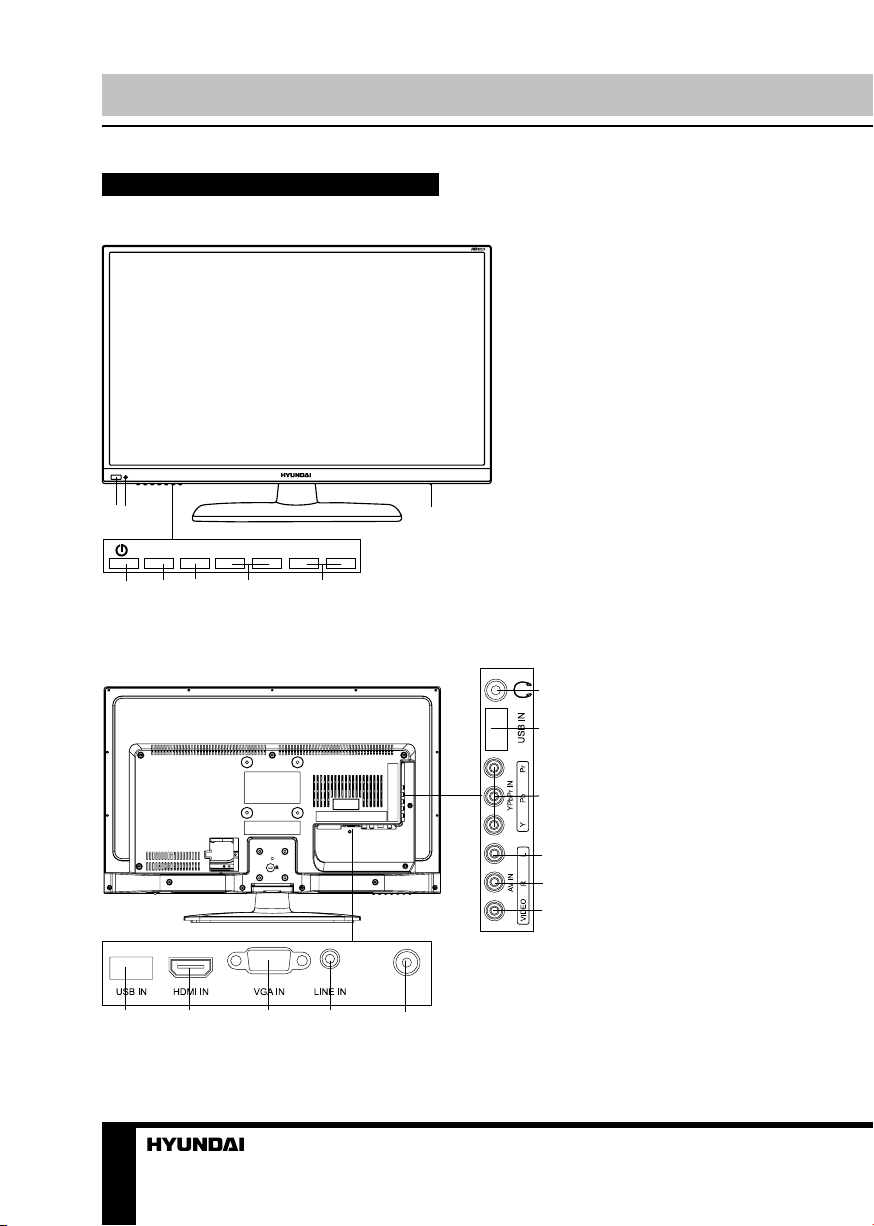
Front panel
2
1
SOURCE
4
VOL+
MENU
6
5
Back panel
VOL- PROG+
7
PROG-
8
1. Power indicator
2. IR sensor
3. POWER switch
4. POWER button
5. SOURCE button
6. MENU button
7. VOL+/- buttons
8. PROG +/- buttons
3
1. USB port 2
11
2. HDMI input
3. PC (VGA) input
10
4. PC audio input
5. Digital coaxial audio output
6. Video output
9
7. Right audio output
8. Left audio output
9. YPbPr input
8
10. USB port 1
11. Headphone jack
7
6
RF IN
1
6
2 3
4
5

Operation
Remote controller (RC)
1
2
3
4
5
6
7
8
9
10
11
12. YELLOW/S.M. button
13. BLUE/ZOOM buton
14. /SUBTITLE button
23
15. /SIZE button
16. HOLD/ button
17. PR+/PR- button
18. INDEX/ button
19. I/II / NICAM button
20. OK button
21. SOURCE button
22. INFO button
23. POWER button
22
21
20
19
18
17
16
15
14
13
12
Changing the battery
1. Remove the battery compartment cover
on the back of the RC.
2. Insert two AAA batteries into the battery
compartment making sure that the correct
polarity is observed.
3. Install the cover back.
1. button
2. Number buttons
3. RETURN button
4. MENU button
5. Cursor buttons (LEFT/RIGHT/UP/DOWN)
6. TEXT button
7. VOL+/VOL- buttons
8. /MIX button
9. /REVEAL button
10. RED/3D button
11. GREEN/P.M. button
1 2 3
The RC should be pointed at remote sensor
within 8 meters and within 30 degrees at the
left or the right side. Take the battery out of the
RC if it is not used for a long time. Do not mix
new and used batteries or different types of
batteries. Weak batteries can leak and severely
damage the RC. Do not expose the RC to
shock, liquids, and do not place it in an area
with high humidity.
7

Operation
General operations
• Connect the round terminal of the adapter
to the power adapter input of the TV (the
position of the imput is given in paragraph
Control Elements above). Connect the plug
of the adapter to the power supply outlet, the
power indicator will light up in red showing
that the unit is in standby mode. To switch on
the unit, press POWER button on the panel
or on the RC. Press POWER button again to
switch the unit to the standby model, the power
indicator will light up in red. To switch off the
unit completely, disconnect the power adaptor
cord plug from the power supply outlet. If after
connecting the adapter plug to power supply
the power indicator does not light up in red,
please wait for some time and the unit will turn
on automatically (this effect takes place if the
unit had been disconnected from the power
supply without being previously switched to
standby mode).
• Press VOL- button repeatedly to decrease
the volume; press VOL+ button repeatedly to
increase the volume.
• Press to mute sound, press this button
again or increase volume to resume sound.
• Press I/II / NICAM button in TV mode
repeatedly to switch between Nicam Stereo,
Dual I and Dual II sound modes (can be
unavailable for some channels).
• Press SOURCE button on the RC or
on the device, then press UP/DOWN cursor
buttons to cycle through the available source
list as follows: TV - AV - YPbPr - VGA - HDMI
- USB.
• Press repeatedly S.M button to select
sound mode: Personal => Standard => Music
=> Film => News.
• Press repeatedly P.M button to select
picture mode: Personal => Bright => Normal
=> Soft.
• Select the TV function mode. Press
PR-/PR+ buttons to select previous or next
channels; or press number buttons to enter a
channel number from 0 to 200 directly.
• Press STILL button to freeze the picture
on or off.
• Press INFO button to display the preset
TV channel play information.
• Press BLUE/ZOOM button repeatedly to
select an aspect ratio: 16:9/4:3/Panorama/
Zoom1/Zoom2. The set of available aspects
can vary depending on the current signal
source.
Teletext operations (option)
Select a TV channel in order to pick up
the picture signal of Teletext. Teletext button
functions are as follows:
TEXT: Press this button to enter into TEXT
mode. Press this button again to enter mixed
mode. Press the button again to return to the
channel you are watching.
HOLD/ : Press this button to stop the move
to the next page. Press this button again to
cancel operation.
INDEX/ : Press this button to go to the
index page.
REVEAL: Press this button to reveal the
cancelled information. Press this button again
to cancel the information.
Red/Green/Yellow/Blue buttons: Press
these 4 color buttons to access directly to
corresponding color page displayed at the
lower parts of teletext screen.
OSD operation
1. Press MENU button to enter the setting
menu displayed on the screen.
2. Press LEFT/RIGHT cursor buttons on the
RC or VOL+/- buttons on the panel to select
setting page.
3. Press DOWN cursor button or OK button
on the RC or PR+ button on the panel to go to
the parameter list.
4. Press UP/DOWN cursor buttons on the
RC or PR+/- buttons on the panel to select a
parameter to adjust.
5. Press cursor buttons on the RC or VOL+/-
8
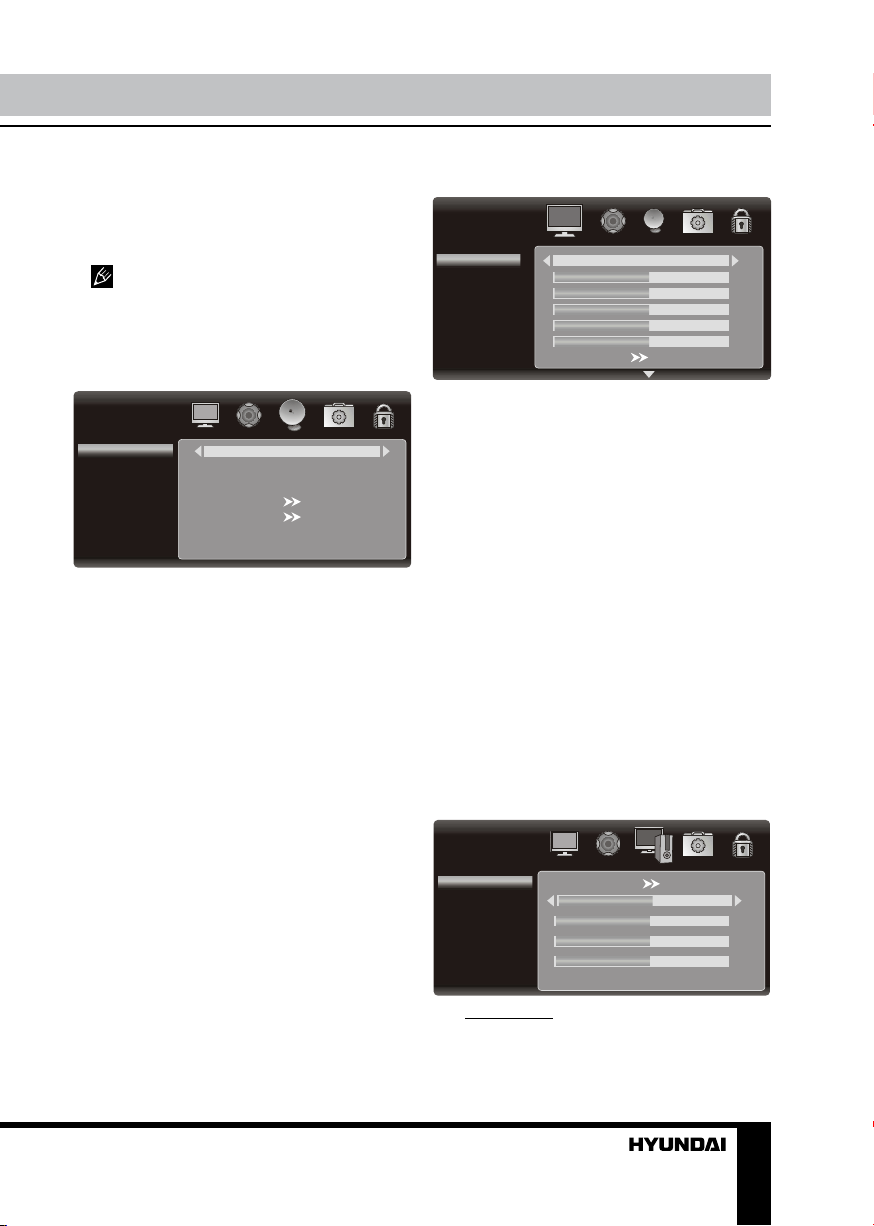
Operation
INSTA LLATION
Channel No.
Color System
Sound System
Auto Search
Manu al Search
Fine Tuning
Channel Skip
1
PAL
BG
208.25MH z
Off
PC
Auto Adjust
H. Position
V. Position
Phase
Frequency
50
50
50
50
PICTUR E
Picture Mode
Brightness
Contrast
Color
Sharpness
Color Temperature
Tint
50
Soft
50
50
50
50
or CH+/- buttons on the panel to adjust the
selected parameter.
6. Press MENU button to return to the
previous menu page. Press RETURN button
on the RC to quit the menu.
Some menu items may be in grey color,
in this case they are not adjustable. Pictures
of OSD menu are for reference only; they may
differ from the real screens.
Channel setting (only for TV source)
• Channel No.: Sets the received TV
channel No.
• Color system: select corresponding color
system.
• Sound system: select corresponding
sound system.
• Auto search.
• TV manual tuning: press LEFT/RIGHT
buttons; the unit will search for next available
channel downward or upward and save it
under the current number.
• Fine tuning: perform fine adjustment of
the current frequency.
• Channel skip: You can skip unnecessary
program channels of your choice not to be
displayed during viewing and scanning when
pressing the PR+/- buttons. Select “OFF” by
pressing LEFT/RIGHT buttons to select the
channel that would not skip the channel scan
operation.
Picture setting
• Picture Mode: Personal/Bright/Normal/
Soft.
• Brightness
• Contrast
• Color
• Tint: adjust the tone of color when your
system is in NTSC.
• Sharpness
• Display mode: Panorama, Movie,
Caption, 16:9, 4:3 and Auto.
• DNR: select between four modes of digital
noise reduction available: Off / Low / Middle /
High.
• Backlight: Adjust peak brightness of the
backlight (Low / Middle / High)
• Color Temperature: Cool / Neutral /
Warm / Personal.
• Red: Adjust the red level of the image.
• Green: Adjust the green level of the image.
• Blue: Adjust the blue level of the image.
Screen setting (only for PC mode)
• Auto adjust: automatical setting of the
parameters.
• H. Position: adjust horizontal position of
9
 Loading...