

Page 1
Hi40402JO1E
Robot Operation Manual
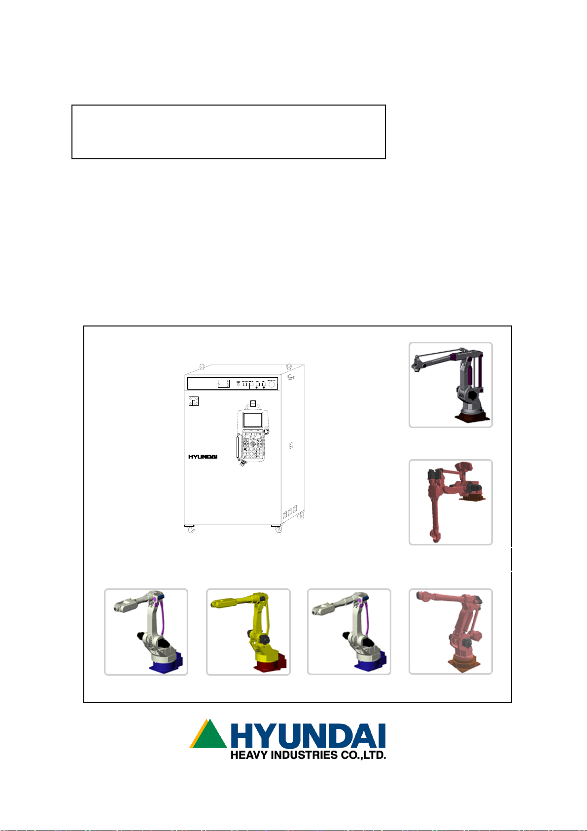
HYUNDAI Robot
Hi4
TP300
HYUNDAI
PF1
PF2
PF4
PF3
축
좌표계
직교
보조축
GUN 연속
TOOL
SHIFT
후진
(고속)
속도
스텝
EN. SW
전진
MOTOR
보조점9I,V변경
*
f1
7
8
ARCON
송출( )WEAVON
4
526
?
ARCOF
후퇴( )
WEAVOF
교시
/
1
3
재생f2f3
+
삭제 프로그램
LCD
.
0
f4
Hi4 CONTROLLER
E.STOP
PF5
OFF
ACC
직선
보간
원호
취소
Rx+
Rx-
Ry+
Ry-
Rz+
Rz-
명령수정
위치수정
CMD
MOVE
정지
문/변/함
수동출력
지난화면
STEP
HR100P
HR120S/150S
HR006
HR015
HR010L
HX130/165
Page 2

The information presented in the manual is the property
of HHI. Any copy or even partial is not allowed without
prior written authorization from HHI. HHI reserves the
right to modify without prior notification.
Printed in Korea - April/2002. 1st Edition
Copyright
2002 by Hyundai Heavy Industries Co.,Ltd.
Page 3

■ HEAD OFFICE ■ 본사
1, JEONHA-DONG, DONG-GU, 울산광역시 동구 전하동 1번지
ULSAN, KOREA
TEL: 82-52-230-7901~11 TEL: 052-230-7901~11
FAX: 82-52-230-7900 FAX: 052-230-7900
■ SEOUL OFFICE ■ 서울사무소
140-2,GYE-DONG, JONGNO-GU, 서울특별시 종로구 계동 140-2
SEOUL,KOREA 현대빌딩 14층
TEL: 82-2-746-4711~5 TEL: 02-746-4711~5
FAX: 82-2-746-4720 FAX: 02-746-4720
■ DAEGU OFFICE ■ 대구사무소
223-5, BUMEO 2-DONG, 대구광역시 수성구 범어 2동 235-5번지
SUSUNG-GU,DAEGU,KOREA 동일산업빌딩 6층
TEL : 82-53-746-6232 TEL: 053-746-6232
FAX : 82-53-746-6231 FAX: 053-746-6231
■ CHEONAN OFFICE ■ 천안사무소
355-15,DAGA-DONG,CHEONAN-SI, 충청남도 천안시 다가동 355-15번지
CHUNGCHEONGNAM-DO,KOREA 3층
TEL: 82-41-576-4294~5 TEL: 041-576-4294~5
FAX: 82-41-576-4296 FAX: 041-576-4296
■ GWANGJU OFFICE ■ 광주사무소
415-12,NONGSUNG-DONG, 광주광역시 서구 농성동 415-12번지
SEO-GU,GWANGJU,KOREA 현대빌딩 별관 3층
TEL: 82-62-363-5272 TEL: 062-363-5272
FAX: 82-62-363-5273 FAX: 062-363-5273
Page 4

------------------------------------------------------------------------------------------------
Contents
Chapter 1. Safety, Operation panel, Teach Pendant
1.1 Safety ..................................................... 1 - 2
1.1.1 General .................................................... 1 - 2
1.1.2 Relevant safety standard ................................... 1 - 5
1.1.3 Safety training ............................................ 1 - 5
1.1.4 Safety marking ............................................. 1 - 5
1.1.5 Definition of safety functions ............................. 1 - 7
1.1.6 Installation of robot ...................................... 1 - 8
1.1.7 Safety working procedures ................................. 1 - 15
1.1.8 Safety measures for entering safety fence ................. 1 - 20
1.1.9 Safety measures for maintenance and repair ................ 1 - 21
1.1.10 Safety function ........................................... 1 - 24
1.1.11 Safety related to end effectors ........................... 1 - 28
1.1.12 Liabilities ............................................... 1 - 29
1.2 Operation Panel............................................ 1 - 31
1.2.1 External shape of operation panel ......................... 1 - 31
1.2.2 Buttons of operation panel ................................ 1 - 31
1.3 Teach pendant ............................................. 1 - 33
1.3.1 External shape of teach pendant ........................... 1 - 33
1.3.2 Screen of teach pendant ................................... 1 - 34
1.3.3 Keys of teach pendant ..................................... 1 - 35
Chapter 2. Basic operation of robot
2.1 Basic operation............................................ 2 - 2
2.1.1 Controller's power/motor ON/OFF ........................... 2 - 2
2.1.1.1 Power ON/Motor ON ........................................ 2 - 2
2.1.1.2 Power OFF/Motor OFF ....................................... 2 - 2
2.1.2 How to initiate the system ................................ 2 - 3
2.1.3 Teaching .................................................. 2 - 3
2.1.4 Step and function ......................................... 2 - 4
----------------------------------------------------------------------------------------
- 1 -
Page 5

------------------------------------------------------------------------------------------------
2.2
Basic things for step
....................................... 2 - 5
2.2.1 The parameter of STEP command line ........................ 2 - 5
2.2.1.1 Interpolation-locus from between step and step ............ 2 - 6
2.2.1.2 Pose ..................................................... 2 - 7
2.2.1.3 Speed .................................................... 2 - 8
2.2.1.4 Accuracy ................................................. 2 - 8
2.2.1.5 Tool number .............................................. 2 - 8
2.2.1.6 Output option ............................................ 2 - 8
2.2.1.7 Stop condition ............................................ 2 - 9
2.2.1.8 Stop state variable ...................................... 2 - 9
2.2.2 Step position validation/modification method.............. 2 - 10
2.2.2.1 Encoder coordinate system ................................ 2 - 10
2.2.2.2 Base/Robot coordinate system ............................ 2 - 11
2.1.4 Coordinate system ........................................ 2 - 13
2.3.1 JOG operation key ....................................... 2 - 13
2.3.2 Axis coordinate ......................................... 2 - 14
2.3.3 Robot coordinate ........................................ 2 - 15
2.3.4 User coordinate ......................................... 2 - 17
2.3.5 Tool coordinate ......................................... 2 - 18
2.4 Auto tool setting ........................................ 2 - 19
Chapter 3. Service menu
3.1 Monitoring .................................................... 3 - 4
3.2 Register ..................................................... 3 - 15
3.2.1 XYZ Shift register ................................... 3 - 16
3.2.2 Shift buffers ........................................ 3 - 18
3.2.3 On-line shift register Group.......................... 3 - 20
3.2.4 Palletizing register.................................. 3 - 22
3.2.5 Frequency condition register.......................... 3 - 25
3.2.6 Conveyor data ........................................ 3 - 26
3.3 Variable ...................................................... 3 - 28
3.4 Edit program .................................................. 3 - 29
3.4.1 Modify writing condition totally...................... 3 - 30
3.4.2 Modify speed in record totally........................ 3 - 31
3.4.3 Modify position in record totally..................... 3 - 32
3.4.4 Step copy ........................................... 3 - 34
----------------------------------------------------------------------------------------
- 2 -
Page 6

------------------------------------------------------------------------------------------------
3.4.5 Step reverse copy ..................................... 3 - 36
3.4.6 Edit program in running (Hot edit) ................... 3 - 38
3.5 File management................................................ 3 - 43
3.5.1 Internal memory file name ............................ 3 - 44
3.5.2 Program first data .................................... 3 - 45
3.5.3 Internal program axis no. ............................. 3 - 46
3.5.4 Rename ............................................... 3 - 47
3.5.5 Copy.................................................. 3 - 51
3.5.6 Delete ............................................... 3 - 53
3.5.7 Protect............................................... 3 - 55
3.5.8 Storage media format ................................. 3 - 58
3.5.9 Save/Load (SRAM Card) ................................ 3 - 59
3.6 Program conversion............................................. 3 - 61
3.6.1 Coordinate transformation ............................ 3 - 62
3.6.2 Mirror Image.......................................... 3 - 64
3.6.3 Off-Line XYZ shift ................................... 3 - 67
3.7 System checking ............................................... 3 - 69
3.7.1 System version ........................................ 3 - 70
3.7.2 Run time ............................................. 3 - 71
3.7.3 Diagnosis of troubles ................................. 3 - 74
3.7.4 Error logging ........................................ 3 - 76
3.7.5 Stop history ......................................... 3 - 78
3.7.6 Operation history .................................... 3 - 80
3.8 Date setting (Date, Time) ..................................... 3 - 81
Chapter 4. Condition setting
4.1 Cycle type ...................................................... 4-3
4.2 Step go/back max. speed .......................................... 4-3
4.3 Function in step go/back .........................................4-4
4.4 Speed rate....................................................... 4-4
4.5 Robot lock....................................................... 4-5
4.6 Record speed type................................................4-5
4.7 Interpolation base...............................................4-6
4.8 User coordinate ................................................. 4-6
----------------------------------------------------------------------------------------
- 3 -
Page 7

------------------------------------------------------------------------------------------------
Chapter 5. Application condition
5.1 Conveyor operation .......................................... 5 - 3
5.2 Search range ................................................ 5 - 4
5.3 Search reference position record ............................. 5 - 4
5.4 Spot welding ................................................ 5 - 5
5.5 Gun search reference record .................................. 5 - 6
5.6 Output(DO) signal clear ...................................... 5 - 7
5.7 Online shift register clear .................................. 5 - 7
Chapter 6. System setting
6.1 User configuration .......................................... 6 - 5
6.1.1 Display language ..................................... 6 - 6
6.1.2 Pose reocrd type .................................... 6 - 6
6.1.3 Start type ........................................... 6 - 7
6.1.4 Change of cursor position in auto mode ............... 6 - 7
6.1.5 Confirm when the command delete....................... 6 - 8
6.1.6 WAIT(DI/WI) forcible release ......................... 6 - 8
6.1.7 Dettachment of Teach Pendant ......................... 6 - 9
6.1.8 Power failure detection(Not changeable) .............. 6 - 9
6.1.9 External program selection ........................... 6 - 9
6.1.10 Using the program strobe signal .................... 6 - 10
6.1.11 Step set alarm type................................. 6 - 11
6.1.12 Lowest position proportion of the cursor ........... 6 - 11
6.1.13 Using the collision sensor ......................... 6 - 12
6.2. Controller parameter ....................................... 6 - 13
6.2.1 Input/output signal selection ....................... 6 - 14
1: Input signal logic ............................... 6 - 15
2: Output signal logic .............................. 6 - 16
3: The attribution of output signal ................. 6 - 17
4: Setting the pulse table .......................... 6 - 18
5: Setting the delay table .......................... 6 - 19
6: Output signal assignment ......................... 6 - 20
7: Input signal assignment .......................... 6 - 21
8: Setting the earlier output ....................... 6 - 23
9: DIO name edit..................................... 6 - 24
----------------------------------------------------------------------------------------
- 4 -
Page 8

------------------------------------------------------------------------------------------------
10: Setting the field bus ............................. 6 - 26
6.2.2 Serial port ......................................... 6 - 31
1: Teach Pendant (CNTP) ............................. 6 - 31
2: Private serial port for I/O board ................ 6 - 31
3: Serial port #1 (CNSIO) ........................... 6 - 32
4: Serial port #2 (OPSIO) ........................... 6 - 33
6.2.3 Robot ready ......................................... 6 - 34
6.2.4 Home position registration .......................... 6 - 35
6.2.5 Return to the previous position ..................... 6 - 36
6.2.6 End relay output time ............................... 6 - 37
6.2.7 Interlock error time ................................ 6 - 38
6.2.8 External error output ............................... 6 - 39
6.2.9 Power Saving : PWM OFF .............................. 6 - 42
6.2.10 Shift limit ........................................ 6 - 43
6.2.11 Setting the user key ............................... 6 - 44
6.2.12 Coordination system registration ................... 6 - 46
1: User coordination registration ................... 6 - 46
2: Pedestal tool coordination system ................ 6 - 48
6.3 Machine parameter............................................ 6 - 49
6.3.1 Tool data ........................................... 6 - 50
6.3.2 Axis Constant ....................................... 6 - 54
6.3.3 Soft limit .......................................... 6 - 55
6.3.4 Arm interference angle .............................. 6 - 56
6.3.5 Encoder offset calibration .......................... 6 - 57
6.3.6 Accel./Decel. speed parameter ....................... 6 - 59
6.3.7 B축 axis dead zone .................................. 6 - 60
6.3.8 Accuracy ............................................ 6 - 61
6.3.9 Speed ............................................... 6 - 64
6.3.11 Additional load per each axis ...................... 6 - 65
6.4 Application parameter ....................................... 6 - 67
6.4.1 Spot & Stud ......................................... 6 - 68
1: Welding parameter ................................ 6 - 69
2: Servo gun parameter .............................. 6 - 71
3: Spot welding data(condition,sequence) ............ 6 - 76
4: Equalizing parameter ............................. 6 - 81
----------------------------------------------------------------------------------------
- 5 -
Page 9

------------------------------------------------------------------------------------------------
6.4.2 Arc ................................................ 6 - 83
6.4.3 Palletizing ........................................ 6 - 85
1: Palletizing pattern register ..................... 6 - 86
2: Pallete dip angle measurement .................... 6 - 90
6.4.6 Conveyor ........................................... 6 - 91
1: Conveyor constant setting ........................ 6 - 92
2: Automatic setting of conveyor parameter .......... 6 - 95
6.4.7 Speed proportion voltage output ..................... 6 - 96
6.5 System format ............................................... 6 - 98
6.5.1 System format ....................................... 6 - 99
6.5.2 Robot type selection ................................ 6 - 100
6.5.4 Use setting ........................................ 6 - 103
6.5.5 Positioner group setting ............................ 6 - 104
6.6 Automatic constant setting ................................. 6 - 106
6.6.1 The optimization axis constant ...................... 6 - 107
6.6.4 Positioner calibration .............................. 6 - 109
Chapter 7. R code
7. 1 (1) R0 Step counter reser ............................ 7 - 5
7. 2 (2) R5 External start selection ...................... 7 - 5
7. 3 (3) R6 External program selection ..................... 7 - 6
7. 4 (4) R10 Run time display............................... 7 - 7
7. 5 (5) R17 File name display in internal memory ......... 7 - 10
7. 6 (6) R18 Frequency condition register .................. 7 - 11
7. 7 (7) R29 Tool number setting .......................... 7 - 12
7. 8 (8) R44 Conveyor data clear .......................... 7 - 13
7. 9 (9) R45 Conveyor register manual input ............... 7 - 14
7.10 (10) R46 Manual conveyor limit switch on .............. 7 - 15
7.11 (11) R49 Speed variation setting ...................... 7 - 16
7.12 (12) R55 Palletize counter reset ...................... 7 - 17
7.13 (13) R71 Recorded speed selection...................... 7 - 18
7.14 (14) R107 Program head data display .................... 7 - 19
7.15 (15) R115 Program copy ................................. 7 - 19
7.16 (16) R116 Program number modification .................. 7 - 20
7.17 (17) R117 Program delete ............................... 7 - 21
----------------------------------------------------------------------------------------
- 6 -
Page 10

------------------------------------------------------------------------------------------------
7.18 (18) R123 Robot lock ................................... 7 - 22
7.19 (19) R136 Modify accuracy in steps ..................... 7 - 23
7.20 (20) R137 Modify MX in steps ............................ 7 - 24
7.21 (21) R138 Modify GUN in steps .......................... 7 - 25
7.22 (22) R162 Shift register value change .................. 7 - 26
7.23 (23) R163 On-line shift cancel ......................... 7 - 26
7.24 (24) R204 Spot welding condition manual output ......... 7 - 27
7.25 (25) R210 Serovo gun number selection .................. 7 - 28
7.26 (26) R211 Squeeze force setting ........................ 7 - 28
7.27 (27) R212 Moving-tip consumption preset ................. 7 - 29
7.28 (28) R213 Fixed-tip consumption preset .................. 7 - 29
7.29 (29) R219 Equalizerless gun number selection ........... 7 - 30
7.30 (30) R220 Equalizerless tip consumption preset .......... 7 - 30
7.31 (31) R245 Monitor mode selection ........................ 7 - 31
7.32 (32) R269 Memory protection setting ..................... 7 - 32
7.33 (33) R286 Software version display ...................... 7 - 33
7.34 (34) R310 Manual output of GO-signal .................... 7 - 34
7.35 (35) R320 Set max. speed of step go/back ................ 7 - 35
7.36 (36) R323 Robot interrupt function record ............... 7 - 36
7.37 (37) R341 Execution code back-up ....................... 7 - 40
Chapter 8. Programming
8.1 Edit step..................................................... 8 - 3
8.2 Summary of operation keys ..................................... 8 - 4
8.3 Edit command.................................................. 8 - 6
8.4 Example - move sentence ....................................... 8 - 7
8.5 Variable, numerical formula and string edit .................. 8 - 13
8.6 Line number edit............................................. 8 - 17
8.7 Block edit................................................... 8 - 18
Chapter 9. Quick open function
9.1 Function summary............................................ 9 - 2
9.2 Move - step position ........................................ 9 - 4
9.3 Welding start con. - execution at ASF#=X .................... 9 - 5
9.4 Welding end con. - execution at AEF#=X ...................... 9 - 7
----------------------------------------------------------------------------------------
- 7 -
Page 11

------------------------------------------------------------------------------------------------
9.5 Welding aux. con. - retry .................................. 9 - 9
9.6 Welding aux. con. - restart................................ 9 - 11
9.7 Welding aux. con. - auto. wire stick release. .............. 9 - 14
9.8 Weaving condition file .................................... 9 - 15
9.9 Program edit in running ................................... 9 - 17
9.10 Spot welding function ..................................... 9 - 18
9.10.1 Welding condition ........................................ 9 - 18
9.10.2 Welding sequence .......................................... 9 - 19
Chapter 10. Menu tree
10.1 MENU LIST .................................................. 10 - 2
10.2 MOTION I/O ................................................. 10 - 3
10.3 FLOW CONTROL ............................................... 10 - 5
10.4 ETC. ....................................................... 10 - 7
10.5 ARC ........................................................ 10 - 8
10.6 SUSTITUTIAL STATEMENT ..................................... 10 - 10
Chapter 11. Robot language explanation
11.1 BASIC ELEMENTS ............................................ 11 - 3
11.1.1 LINE ............................................. 11 - 3
11.1.2 CHARACTER ........................................ 11 - 3
11.1.3 ADDRESS .......................................... 11 - 3
11.1.4 CONSTANT ........................................ 11 - 4
11.1.5 ROBOT CONFIG. INFORMATION.......................... 11 - 5
11.1.6 VARIABLE ......................................... 11 - 6
11.1.7 OPERATOR ........................................ 11 - 10
11.1.8 FORMULA ......................................... 11 - 10
11.2 COMMAND LINE .............................................. 11 - 11
11.2.1 SUSTITUTIONAL ................................... 11 - 11
11.2.2 ROBOT CONTROL ................................... 11 - 12
11.2.3 INPUT/OUTPUT .................................... 11 - 14
11.2.4 PROGRAM FLOW CONTROL ............................. 11 - 16
11.2.5 COMMENT ......................................... 11 - 21
11.2.6 ARC WELDING ..................................... 11 - 21
11.3 OTHERS. ................................................... 11 - 25
----------------------------------------------------------------------------------------
- 8 -
Page 12

------------------------------------------------------------------------------------------------
11.4 FUNCTION................................................... 11 - 40
11.4.1 ARITHEMATIC FUNCTION ............................. 11 - 40
11.4.2 STRING FUNCTION .................................. 11 - 41
11.4.3 ROBOT LANGUAGE SUBTITUTION OF OLD MIT FUNCTION CODE 11 - 42
Chapter 12. Signal connection
12.1 EXTERNAL INPUT SIGNAL (BD430/BD431) ......................... 12 - 2
12.2 EXTERNAL OUTPUT SIGNAL (BD430/BD431) ........................ 12 - 7
12.3 BD481 CIRCUIT ............................................. 12 - 17
----------------------------------------------------------------------------------------
- 9 -
Page 13

------------------------------------------------------------------------------------------------
1. Safety, Operation Panel, Teach Pendant (1) Safety
Chapter 1.Safety, Operation
panel, Teach pendant
Contents
━━━━━━━━━━━━━━━━━━━━━━━━━━━━━━━━━━━━━━━━━━━━━
1.1 Safety ..................................................... 1 - 2
1.1.1 General .................................................... 1 - 2
1.1.2 Relevant safety standard ................................... 1 - 5
1.1.3 Safety training ............................................ 1 - 5
1.1.4 Safety marking ............................................. 1 - 5
1.1.5 Definition of safety functions ............................. 1 - 7
1.1.6 Installation of robot ...................................... 1 - 8
1.1.7 Safety working procedures ................................. 1 - 15
1.1.8 Safety measures for entering safety fence ................. 1 - 20
1.1.9 Safety measures for maintenance and repair ................ 1 - 21
1.1.10 Safety function ........................................... 1 - 24
1.1.11 Safety related to end effectors ........................... 1 - 28
1.1.12 Liabilities ............................................... 1 - 29
1.2 Operation Panel ............................................ 1 - 31
1.2.1 External shape of operation panel ......................... 1 - 31
1.2.2 Buttons of operation panel ................................ 1 - 31
1.3 Teach pendant ............................................. 1 - 33
1.3.1 External shape of teach pendant ........................... 1 - 33
1.3.2 Screen of teach pendant ................................... 1 - 34
1.3.3 Keys of teach pendant ..................................... 1 - 35
------------------------------------------------------------------------------- 1 - 1
Page 14

1. Safety, Operation Panel, Teach Pendant (1) Safety
------------------------------------------------------------------------------------------------
Chapter 1. Safety, Operation panel, Teach Pendant
1.1 Safety
1.1.1 General
The primary purpose of this Chapter is to define the safety of the user and operating
personnel when using Hyundai Industrial Robots i. e. HR series and HX series robot
together with Hi-4 Controller (Hereinafter referred to "the Robotics System").
This manual covers any functions and safety measures required for the operation and
maintenance of the Robotics System itself. However, this manual does neither cover
how to design, install and operate a complete work cell, nor all peripheral equipment
and tooling which can influence the safety of the complete work cell.
This manual enumerates the safety instructions and/or recommendations for robot
manipulator and controller in strictly accordance with the American National Standard
Safety Requirements for industrial robots "ANSI/RIA R15.06-1999".
The technical description and installation method of the Robotics System are
presented in detail at this Operation Manual and the relevant specifications for the
robot manipulator and controller.
All personnel who intend to install, operate, program, repair, adjust, maintain or
otherwise use the Robotics System must be trained in an approved Hyundai Robotics
training course and have a good understanding and knowledge of this Operation Manual
and the Maintenance Manual, and further pay their special attention and observation
to the articles marked with the symbol which are of paramount importance among
the articles in this Chapter 1 "Safety".
Installation, replacement, adjustment, operation, maintenance and repair of the
Robotics System must be performed by the personnel who was duly trained in an approved
Hyundai robotics training course and become familiar with the proper operation of
the Robotics System according to the instructions specified in Operation and
-------------------------------------------------------------------------------1 - 2
Page 15

------------------------------------------------------------------------------------------------
1. Safety, Operation Panel, Teach Pendant (1) Safety
Maintenance Manual. Hyundai maintains its various application-specific training
courses for domestic and foreign customers respectively.
All owners, employers or users of the Robotics System have the responsibility to
review and observe any appliable safety laws and regulations in each country and to
take the necessary steps to guarantee the correct design, installation and operation
of all safety devices which can secure safety of all personnel in the workplace.
In accordance with the American National Standard Safety Requirements for industrial
robots "ANSI/RIA R15.06-1999", the dangerous zones of the Robotics System, i. e. the
working range in which the robot together with tools, accessories and additional
equipment moves, must in all cases be safeguarded to prevent persons or objects from
entering the dangerous zones or to ensure that the robot system is immediately shut
down by Emergency Stop system if a person or object should nevertheless enter a
dangerous zone. All owners, employers or users of the Robotics System have the
responsibility to take all necessary steps to make correct installation, examination
and operation of the relevant safety equipments.
This manual provides specific information regarding the operation of Hyundai Hi-4
Controller together with the following robot manipulator models for the possible
application usages as mentioned below;
Available manipulator Type
HR006F(floor mounting type, 6kg)
HR006V(wall mounting type, 6kg)
HR015F(floor mounting type, 15kg)
HR015V(wall mounting type, 15kg)
HR050F(floor mounting type, 50kg)
HR050V(wall mounting type, 50kg)
HR100P(for palletizing application, 100kg)
HR130IIF(floor mounting type, 130kg)
HR130IIV(wall mounting type, 130kg)
HR120S (shelf mounting type, 120kg)
HR150S (shelf mounting type, 150kg)
HX130F (floor mounting type, 130kg)
------------------------------------------------------------------------------- 1 - 3
Page 16

1. Safety, Operation Panel, Teach Pendant (1) Safety
------------------------------------------------------------------------------------------------
HX130V (wall mounting type, 130kg)
HX130S (shelf mounting type, 130kg)
HX165F (floor mounting type, 165kg)
HX165V (wall mounting type, 165kg)
HX165S (shelf mounting type, 165kg)
Possible Application Usages
The Robotics System is a standard six-axis but additional axis available industrial
robot for installation on the floor, on the wall or on the shelf. It is suitable for
both point-to-point and continuous-path controlled tasks.
The main areas of application are
- Spot welding
- Material Handling
- Assembly
- Application of adhesives, sealants and preservatives
- MIG/MAG welding
- Palletizing and Depalletizing
- Grinding
All owners, employers or users who intend to use the Robotics System for any other
purposes than the above-mentioned must request Hyundai's prior consideration and
confirmation whether it can be applied without failure and/or problems or not.
Please contact our Customer Satisfaction Department or your local distributor in
order to check and confirm it before any users implement any special applications
of the Robotics System.
Invalid environments
The Robotics System is strictly prohibited to be located, installed, maintained,
used or operated in an explosive environment and any areas contaminated by oil,
flammable material or chemical material.
-------------------------------------------------------------------------------1 - 4
Page 17

------------------------------------------------------------------------------------------------
1. Safety, Operation Panel, Teach Pendant (1) Safety
1.1.2 Relevant Safety Standards
The Robotics System is designed as per ISO 10218, January 1992 edition that specifies
the Safety Requirements for Industrial Robots and furthermore in strictly accordance
with the ANSI/RIA 15.06 -1999 Safety Requirements.
1.1.3 Safety Training
All the personnel who intend to teach, operate or examine the Robotics System must
be trained in an approved Hyundai Robotics operation and safety training course before
starting the teaching, operation or examination of the Robotics System.
The objective of the operation and safety training course is to provide information
on:
- the purpose of safety devices and their function
- safety procedures for handling the Robotics System
- performances of the robot or the Robotics System and possible hazards
- tasks associated with any specific robot applications
- safety concepts
1.1.4 Safety Marking
1.1.4.1 Safety Symbols
For the purpose of effective safety instructions, the following safety symbols are
used in this manual.
------------------------------------------------------------------------------- 1 - 5
Page 18

1. Safety, Operation Panel, Teach Pendant (1) Safety
------------------------------------------------------------------------------------------------
!
1.1.4.2 Safety Marking
means
WARNING:
means
MANDATORY:
means
PROHIBTED:
Indicate a potentially hazardous situation which,
if not avoided, could result in death or serious
injury to personnel and damage to equipment.
The special attention to the careful operation and
handling must be paid by owner, employer,
operator or user.
Indicate the compulsory measures that should
be performed by owner, employer, operator and
user
Indicate the prohibited actions and/or
operations that should not be performed by
Identification plates, warning labels and safety symbols are attached to the robot
manipulator and to the inside and outside of control cabinet. The designation labels
and position marks are also attached to the following cables.
- Wire harness between the robot manipulator and the control cabinet
- All the electric cables in and outside both robot manipulator and control
cabinet
All of these plates, labels, symbols and marks constitute safety-relevant parts of
the Robotics System. They must remain attached to the robot manipulator or control
cabinet at their cleary visible positions all the time.
The painted markings on the floor and the signs indicating the dangerous zones must
be clearly different in form, color and style from other markings on the machine near
to the Robotics System or inside the plant facilities where the Robotics System is
installed.
It is forbidden to remove, erase, cover, paint over or alter by way of
editing or spoiling the cleary visible identification plates, warning labels,
safety symbols, designation labels and cable marks
-------------------------------------------------------------------------------1 - 6
Page 19

------------------------------------------------------------------------------------------------
1. Safety, Operation Panel, Teach Pendant (1) Safety
1.1.5. Definition of Safety Functions
Emergency Stop Function- IEC 204-1,10,7
There is one emergency stop button on the controller and another on the teach pendant.
If necessary, additional emergency buttons can be connected to the robot's safety
chain circuit. The emergency stop function, which overrides all other robot controls,
removes drive power from robot axis actuators, stop all moving parts and disconnect
power in order not to use other dangerous functions controlled by the robot.
Safety Stop Function-ISO 10218(EN 775), 6.4.3
When a safety stop circuit is provided, each robot must be delivered with the
necessary connections for the safeguards and interlocks associated with this circuit.
The robot has a number of electrical inputs which can be used to connect external
safety equipment, such as safety gates and light curtains. This allows the robot's
safety functions to be activated both by peripheral equipment and by the robot itself.
Speed Limitation Function-ISO 10218(EN 775), 3.2.17
In manual mode, the speed of robot is strictly limited to 250 mm per second as a
maximum. The speed limitation applies not only to the TCP(Tool Center Point), but
to all parts of robot. The speed of equipment mounted on the robot can be monitored.
Working Envelope Restriction- ANSI/RIA R15.06-1999
The working envelop of each robot axes can be restricted using software limits. Axis
1,2,3 can also be restricted by means of mechanical stops.
Operation Mode Selection- ANSI/RIA R15.06-1999
The robot can be operated either manually or automatically. In manual mode, the robot
can be operated by using the teach pendant only, i. e. not by any external equipment.
------------------------------------------------------------------------------- 1 - 7
Page 20
1. Safety, Operation Panel, Teach Pendant (1) Safety
------------------------------------------------------------------------------------------------
1.1.6. Installation of Robot
1.1.6.1 Safety Fence
!
(1) Install Safety Fence away from the working space of robot in order to prevent
from any possible collision and interface between workers and robot during the robot
operation.
Any accidents can be take place when any workers or any other persons enter inside
the safety fence without protective actions. Safety fence shall be equipped with the
emergency stop mechanism that can activate emergency stop of robot if any workers
would get into the safety fence for examination of robot and welding equipment and
replacement of tip dresser and tip etc. during robot operation.
(2) Safety Fence shall fully cover the working space of robot and be installed to
secure the enough space in order to evade any interference with robot during
teaching and repair operation of workers within the safety fence. And it shall be
-------------------------------------------------------------------------------1 - 8
Page 21

------------------------------------------------------------------------------------------------
1. Safety, Operation Panel, Teach Pendant (1) Safety
tightly fixed to the floor and have the relevant structure not to easily get over
the safety fence.
(3) Safety fence shall be fixed installation type and have no dangerous elements such
as sharp edges and rough profile etc.
(4) Gate shall be installed at Safety Fence. Safety plug shall be attached to gate.
Unless unplug the safety plug from gate, gate shall not be opened. In case of
unplugging the safety plug, robot shall be motor off by interlock signal. It shall
be hard-wired to cause motors off the robot whenever the gate is opened. (Please
refer to Chapter 12.)
(5) In case of robot operation at the state of unplugging safety plug, it shall be
hard-wired to become a low speed playback mode. (Please refer to Chapter 12)
(6) Emergency stop button shall be installed at workers' easily accessible distance.
(7) If there is no safety fence, a photoelectric switch or mat switch instead of safety
plug shall be installed at all the spaces within the working range of robot. Whenever
workers enter the working range of robot, robot will be automatically stopped.
(8) Working space of robot as the dangerous area shall be clearly marked by painting
on the floor.
1.1.6.2. Installation of robot and peripheral equipment
!
(1) Execute the connection work after ensuring the power-off status. There are many
risks of receiving electric shock due to the usage of high voltage power source
such as 220V, 440V, 80V etc. in case of primary power source connection to robot
controller or peripheral equipment.
(2) Attach the warning tag "No-Access during Operation" at the gate of safety fence
and further educate it as a precaution
(3) Locate controller, interlock panel and any other operation panels outside safety
fence.
------------------------------------------------------------------------------- 1 - 9
Page 22

1. Safety, Operation Panel, Teach Pendant (1) Safety
------------------------------------------------------------------------------------------------
(4) In case of installation of operation stand, attach emergency stop button on it.
Emergency stop shall be available at any time from any locations that can operate
the robot.
(5) Execute cabling and piping work in proper way for robot manipulator, controller,
interlock panel, timer etc. Any loose or protruded cables and/or wires can cause
workers' slippery or disconnection of cable by fork lift.
(6) Locate robot manipulator, controller and operation stand where workers can
!
clearly see the movement of robot manipulator. When operator do not acknowledge
abnormal situation of robot or other workers' working at the robot due to the
invisible situation, operator's robot operation can cause a large accident.
(7) Limit the workable space of robot by utilizing soft limit or mechanical stopper
etc. when the required work space of robot is smaller than the workable space of
robot. In case of abnormal operation, any excessive working out of the workable
space can be stopped previously. (Please refer to Operation and Manipulator
Maintenance Manual)
(8) Install safety curtain or cover for spatters made during welding work which can
cause personal injury or fire accident. In any case, safety curtain or cover shall
be installed to allow operator to clearly see the movement of robot manipulator.
(9) Automatic operation and manual operation which mean the actual operation state
of robot shall be notified to workers even in the distance by easily visible light
or device. Install buzzer or alarming light for sign of starting automatic operation
of robot.
(10) Remove any protrusions, sharp edges at equipments, devices around the robot which
can cause personal injury or any other accidents.
(11) Input and output of workpiece by inserting worker's hands inside safety fence
shall be strictly prohibited due to the risks of pressure or cutting injury
accident.
--------------------------------------------------------------------------------
1 - 10
Page 23

------------------------------------------------------------------------------------------------
1.1.6.3. Robot installation
!
1. Safety, Operation Panel, Teach Pendant (1) Safety
Install robot as per the planning and layout which has been previously reviewed and
studied for the optimized performance and functionality of the robot. In case of bad
installation situation of robot, the serious problems can take place as follows;
- Error of relative position between robot and workpiece during operation.
- Bad performance quality of robot caused by vibration.
- Shortening lifetime of robot
- Cause of serious accidents
The following lists the safety precautions to which careful consideration must be
made by operator, worker or installation persons.
General Safety Precautions
(1) Design and install the robot system in completely compliance with laws,
regulations and safety requirements being valid in the country where the robot
system is installed.
(2) All the workers for the robot system must have the good knowledge on the
information specified in the operation and maintenance manual and also have a good
command of operation and maintenance of the robot.
(3) Installation workers of robot must follow the safety requirements when they face
any safety problems in installation.
(4) System Supplier must ensure that all the circuits utilizing safety function
perfectly perform their functionalities in a safe way.
(5) Install primary power supply which can be disconnected from the place outside
the operation area of the robot.
(6) System supplier must ensure that all the circuits utilizing emergency stop
function perform their functionalities in a safe way.
------------------------------------------------------------------------------- 1 - 11
Page 24

1. Safety, Operation Panel, Teach Pendant (1) Safety
------------------------------------------------------------------------------------------------
(7) For immediate emergency stop, install emergency stop button within operator's
easily accessible distance.
Technical Safety Precautions
(1) Remove any interference problems with peripheral equipments considering
dimension and operating space of the robot.
(2) Evade the installation of robot at the places where have direct ray of sun, many
oil, chemical material, explosives, metal powder or humid and wet atmosphere.
(3) Install at the place where ambient temperature is 0∼ 45℃.
(4) Secure sufficient space for facilitation of disassembly and examination of the
robot.
(5) Install safety fence with a gate so that no worker can enter into the operating
range of robot without permission.
(6) Remove any obstacles out of operating space of robot.
(7) Take the special measure considering heat dynamics in case of installation of
robot at the places where have direct ray of sun or near heating equipment.
(8) Take the special measure in case of installation of robot at the place where there
are a lot of dusty metal powder, chemical dusts in the air.
(9) Install robot not to receive any short circuit from welding gun and equipment.
(Insulate robot arm between spot sun completely)
(10) Grounding is very important for preventing from abnormal operation or electric
shock caused by noise. Observe the following installation method.
- Install exclusive grounding terminal using class 3 or higher grounding
method.(In case of input voltage of 400V or higher, observe special class 3
or higher grounding method.)
-------------------------------------------------------------------------------1 - 12
Page 25

------------------------------------------------------------------------------------------------
1. Safety, Operation Panel, Teach Pendant (1) Safety
- Connect Grounding line into the grounding bus-bar inside the controller.
- In case of direct grounding of the robot by anchoring at floor, two point
grounding both by robot manipulator and by controller can produce closed circuit
and further cause abnormal operation of the robot on the contrary. In this
case, connect the grounding line to the base of robot manipulator and disconnect
to the controller. When robot trembles during stopping operation, check and
examine the grounding status immediately since the possible main causes are
incomplete grounding or closed circuit.
- In using built-in transformer gun, primary power cable can be easily worn out
by directly contacting with the gun. In this case, connect the grounding line
to the base of robot directly and disconnect to controller in order to protect
controller and preventing from any electric shock.
------------------------------------------------------------------------------- 1 - 13
Page 26
1. Safety, Operation Panel, Teach Pendant (1) Safety
------------------------------------------------------------------------------------------------
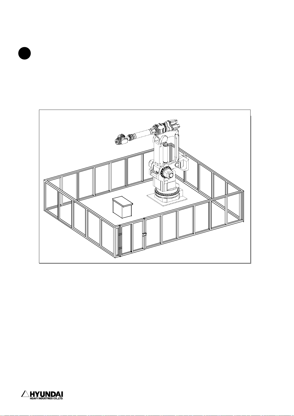
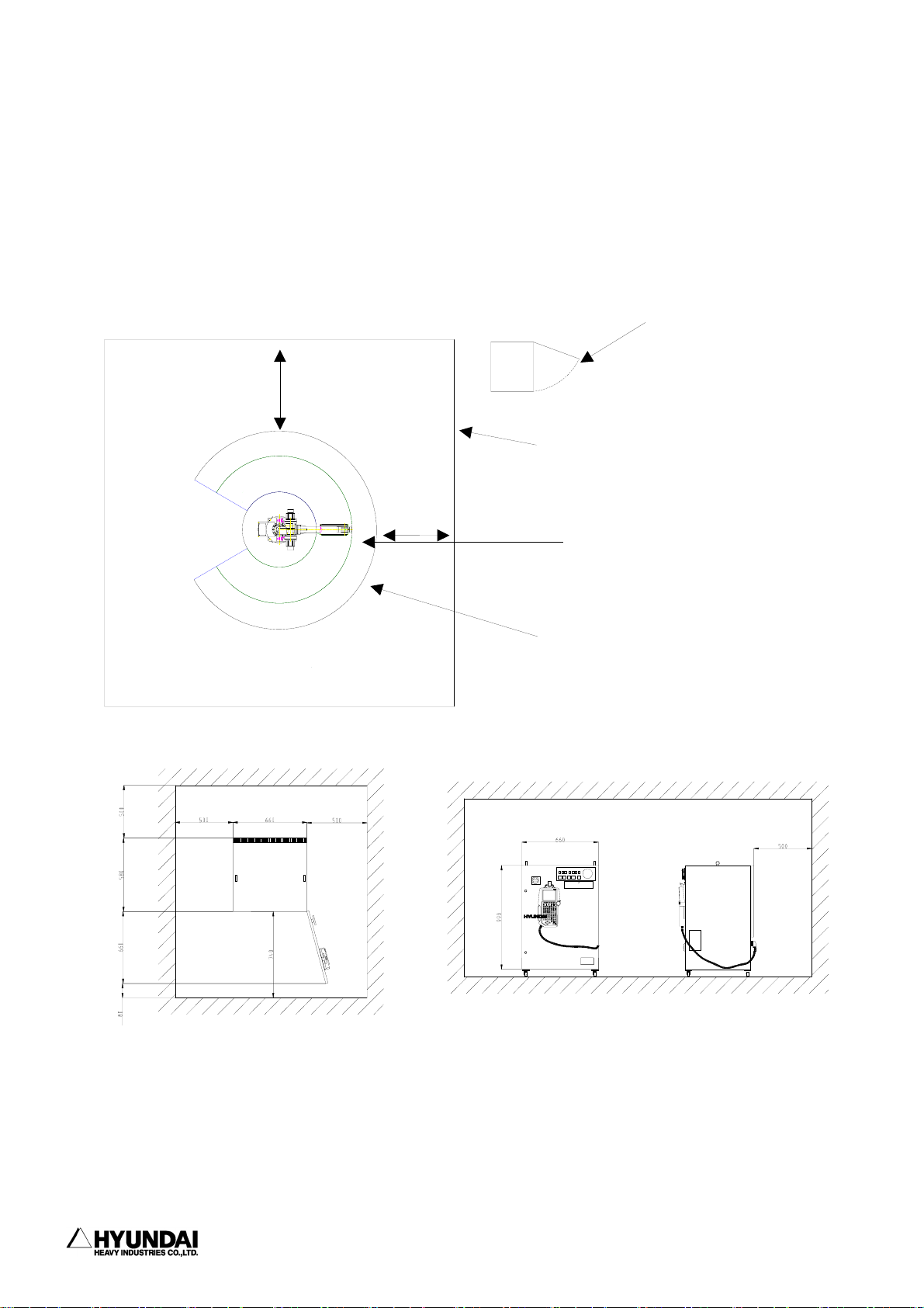
1.1.6.4 Space for robot installation
Install robot manipulator, controller, other peripheral equipment. Be sure that
there are sufficient rooms for maintenance on the manipulator, controller and other
peripheral equipment. Install robot manipulator and controller as per the guideline
as described in the figure below.
1000mm
1000mm
Hi4
controller
Door
Enclosure
Working envelope of
manipulator
Maximum working envelope of
manipulator including Tool or
Workpiece.
Install controller in order that maintenance work can be easily performed when
door open. Secure the maintenance free area whenever robot need to be maintained.
Dimension of controller as specified in the above figure can be changed according
to the kind of controller.
-------------------------------------------------------------------------------1 - 14
Page 27

------------------------------------------------------------------------------------------------
1. Safety, Operation Panel, Teach Pendant (1) Safety
1.1.7. Safety Working Procedures
Safety working procedures must be observed to prevent from any accidents. Safety
device or circuit shall not be modified and disregarded by workers or operators at
any time.
Be careful of any possible accidents caused by electric shock. All normal operations
in automatic mode must be executed outside safety fence. Prior to operation, be sure
there are no personnel within the manipulator's working envelope.
1.1.7.1. Safety measure for robot operation
!
(1) Have the robot system operators, any workers who is possible to operate or any
superintendents attend the training courses held by Hyundai in order that they can
have a good command of safety and robot functions. Do not allow workers who do not
attend the training courses to operate the robot.
(2) Wear safety helmet, safety glass, safety boots during operation.
(3) 2 workers as a team must work together. One worker must supervise through operation
panel while another worker make teaching operation. One worker always must be in
a position to push emergency stop button while another worker execute operation
work inside or outside the operation space of the robot with sufficient cautions.
Furthermore, all the workers must have a good knowledge on escaping route before
their operation work.
(4) Supply power-on after certainly ensuring that there is no persons within operating
space of the robot.
(5) Do teaching work outside the working envelope of the robot, in principle. However,
after motor-off, you may execute work within the working envelope of the robot by
hand-carrying key switch or safety plug, which will prevent from automatic
operation which can be made by any third parties. Furthermore, pay your special
attention to direction of movements which can be made by abnormal or error situation,
if any.
------------------------------------------------------------------------------- 1 - 15
Page 28

1. Safety, Operation Panel, Teach Pendant (1) Safety
------------------------------------------------------------------------------------------------
(6) Superintendent must observe the followings;
- Stay at the place where he can see robot entirely and concentrate on his job of
superintendence.
- Press emergency stop button if there is any abnormal situation.
- keep any people other than the workers who are working for the robot, away from
the working envelope of the robot.
(7) In manual mode, teaching must be made not more than the speed of 250mm/sec.
(8) Do the teaching work by laying of "Under Teaching Operation" signboard all the
time.
(9) Any workers who enter inside safety fence must unplug and bring the safety plug
into the safety fence.
(10) Do not use any equipment which can produce any noise around the place for teaching
work.
(11) Do not operate teach pendant by feeling of hand only but operate it by watching
the keypads clearly.
(12) Pay your careful attention to the movement of the robot. Do not work for the
!
robot under the situation the robot is behind yourself.
(13) Watch your step during your teaching work. In case of high ground teaching work
more than 2 meters, start your work after securing the sufficient safety space for
workers' step-on.
(14) Followings are the counter measures which must be taken in case of any abnormal
!
situations
- Press emergency stop button immediately after finding any abnormal operation.
- When you want to check the abnormal situation after emergency stop, confirm the
stop status of the robot without any fail.
- Robot can stop automatically due to the abnormal power supply. In this case, check
-------------------------------------------------------------------------------1 - 16
Page 29

------------------------------------------------------------------------------------------------
1. Safety, Operation Panel, Teach Pendant (1) Safety
first the stop status of the robot and further investigate the cause to execute
relevant measure.
- When the emergency stop function does not work, disconnect the power supply
immediately and further investigate the cause to execute relevant measure.
- No one who have no operation and maintenance training provided by Hyundai can be
authorized to do the investigation of the cause for abnormal situations. In the
event of emergency stop, re-start of motor must be made by the defined procedure
only after implementing the measure as a result of the detailed investigation
to the cause for abnormal operation.
(15) Prepare relevant working manual on robot operation, working method and the
required action for abnormal situations according to the installation places and
working contents. Proceed with any works as per the relevant working manual.
(16) Precautions during the stop of robot
Do not access to the robot even though the robot is just stopping. There can be
a serious accident caused by sudden movement of robot when you access to the stopped
robot without any precaution. Followings are the cases that the robot is under the
stop status.
No. Robot Situation Motor Accessible or not
Temporary stopping
1
(small problem,Temporary stop switch)
Emergency stopping (Serious problem, Emergency stop
2
switch, safety gate)
Input Signal Stand-by from peripheral equipment (START
3
INTERLOCK)
4 During Playback completion ON Not accessible
5 During Stand-by ON Not accessible
ON Not accessible
OFF Accessible
ON Not accessible
Always, pay your careful attention to the unexpected movement of the robot even
though it is the above situation which you can enter to working envelope. Entering
to the working envelope of the robot without any preparation for unexpected
emergency situation must be prohibited at any time.
--------------------------------------------------------------------------------
1 - 17
Page 30

1. Safety, Operation Panel, Teach Pendant (1) Safety
------------------------------------------------------------------------------------------------
Note) As specified in the above table, in case of temporary stopping,
access to the working envelope of the robot is not allowed. However,
when you try to get inside the working envelope of the robot in order
to make corrections for minor problems such as nozzle contact and arc
trouble, enter the working envelope of robot only after following the
same method as you enter the working envelope for teaching work.
(17) When you finish the operation work of robot, do cleaning work for the area inside
the safety fence to remove any tools, oil or foreign material which left on the
floor. Contamination of working area by oil and any left tools can cause slippery
and personal injury. Please do your cleaning and proper arrangement regularly,
1.1.7.2 Safety Measure for Robot Try-out
!
Engineering error, Teaching error and manufacturing defects on the total system
including teaching program, jig and sequence etc. can be found during try-out of the
robot. Therefore, do your try-out operation taking your due consideration into the
safety matter. Safety related accident can took place due to the combined reasons.
(1) Check first the functions of signals and buttons such as emergency stop button
and stop button etc. before robot operation and further check error detection
function. Checking of all the signals for stopping the robot is the most important
thing. When you can foresee the possible accident previously, the most important
thing is to stop the robot.
(2) For the try-out of robot, operate in the lower speed of 20%∼30% and further check
movement more than 1 cycle repeatedly. When you find any problems, modify them
immediately. Afterwards, make speed-up by the order of first 50%, second 75% and
final 100% and further check movement more than 1 cycle for each speed set-up
respectively. When you make speed set-up of high speed at the beginning, the
unexpected accident can take place.
(3) You can not foresee any problems to be made during try-out. Do not enter inside
-------------------------------------------------------------------------------1 - 18
Page 31

------------------------------------------------------------------------------------------------
the safety fence during try-out. Unexpected accidents can take place easily due
to the unreliable situations.
1.1.7.3 Safety measure for automatic operation
!
(1) Educate all the workers not to get inside the safety fence during the operation
while the sign-board "No Access During Operation" must be placed at the gate of
safety fence. When robot is stopping, you can get inside the safety fence after
careful judgment of the situation.
(2) First check and confirm whether there are any persons inside the safety fence
!
when you start your automatic operation. There can be any serious personal injury
when you operate without checking whether there are any persons inside the safety
fence.
1. Safety, Operation Panel, Teach Pendant (1) Safety
(3) Start any automatic operation after confirming that the conditions such as program
No., step No., mode, start selection etc. is relevant for automatic operation. When
you make start operation under the selection of the program or step which is not
valid for automatic operation, there can be serious accidents which is caused by
the unexpected movements of robot.
(4) First confirm whether robot is located at the place where it can be operated in
automatic mode. Further confirm whether program No., step No. and robot location
are correct. Even though program No. and step No. are correct, the wrong location
of robot can cause any serious accident by way of abnormal movement.
(5) You are ready to press emergency stop button during automatic operation. Press
emergency stop button immediately when you face any unexpected abnormal robot
movement or situations.
(6) Check any errors or abnormal status of moving path, moving situation and moving
sound etc. While robot can be failed suddenly, it also can be failed by way of
showing certain sympton of failure. Have your good understanding and recognition
on the normal operation situations of robot.
(7) When you find any abnormal situations, press emergency stop button immediately
!
------------------------------------------------------------------------------- 1 - 19
Page 32

1. Safety, Operation Panel, Teach Pendant (1) Safety
------------------------------------------------------------------------------------------------
and make the necessary action to the abnormal situations. Unless you make any
necessary action, there can be a failure which possibly result in serious personal
accident as well as stop of production.
(8) When you make necessary action for any abnormal situation and check the normal
!
operation, you can check in low speed operation whether abnormal situation is fixed.
However, it must not be checked even in low speed operation under the situation
that any workers stay inside the safety fence. Since it is not reliable situation,
another abnormal situation or any unexpected accident can take place.
1.1.8. Safety Measures for Entering Inside the Safety Fence
!
The robot is extremely heavy and powerful, even at low speed. When entering inside
working envelope of the robot, the applicable safety regulations of the country
concerned must be observed.
Operators must be aware of the fact that the robot can make unexpected movements.
A pause(stop) of robot in pattern of movements may be followed by a movement at high
speed. Operators must be aware of the fact that external signals can affect robot
programs in such a way that a certain pattern of movement change without warning.
During programming and testing, the enabling device must be released as soon as there
is no need for the robot to move.
The programmer must always take the teach pendant with him/her when entering through
the safety gate to the robot's working envelope so that no-one else can take over
control of the robot without his/her knowledge. Hang up the sign-board "Under robot
operation work" in front of the controller.
When you enter inside the working envelope of the robot, keep in mind the following
considerations.
(1) Any workers other than programmer must not be allowed within the working
envelope of the robot.
(2) The operation selector on the teaching pendant must be in the teach lock mode
-------------------------------------------------------------------------------1 - 20
Page 33

------------------------------------------------------------------------------------------------
1. Safety, Operation Panel, Teach Pendant (1) Safety
position.
(3) The operating mode selector on the controller must be in the manual mode position
to block operation from remote control panel.
(4) Always wear approved work clothes(no loose fitting clothes).
(5) Do not wear gloves when operating the Controller.
(6) Do not allow underwear, shirts, or neckties to hang out from the work clothes.
(7) Do not wear large jewelry, such as earring , rings, or pendants.
(8) Always wear protective safety equipment such as helmets, safety shoes(with
slip-proof shoes), face shields, safety glasses, and safety gloves as
necessary.
(9) Before operating the manipulator, confirm that the emergency stop circuit is
functioning by pressing the emergency stop button on the operation panel and
teach pendant, and confirm that MOTOR lamp is turned off.
(10) Always view the manipulator from the front when you execute any work.
(11) Follow the predetermined operating procedure.
(12) Always have an escape method and place in mind in case the manipulator comes
toward you unexpectedly.
1.1.9. Safety Measures for Maintenance and Repair
1.1.9.1. Safety measures for Maintenance and Repair of Controller
!
(1) Have all the workers who wish to maintenance and repair work of the robot attend
the special maintenance training course held by Hyundai.
------------------------------------------------------------------------------- 1 - 21
Page 34

1. Safety, Operation Panel, Teach Pendant (1) Safety
------------------------------------------------------------------------------------------------
(2) Proceed with all the work according to the maintenance and repair procedures.
(3) Check safety conditions around the workers and secure the escaping route and
place in case of any dangerous situation before starting maintenance and repair
work.
(4) Turn OFF the power supply when you start regular maintenance or repair, part
replacement work. To prevent anyone inadvertently turning ON the power supply
during maintenance, put up a warning sign such as "DO NOT TURN ON THE POWER"
at the primary power supply.
(5) Always use the designated part for the replacement of failed part.
(6) Turn OFF when you open the door of Controller.
(7) After turning OFF, wait at least 3 minutes to start any work.
(8) Do not touch the SERVOPACK heat sink and the regeneration resistor since they
become very hot.
(9) After maintenance is completed, carefully check that no tools are left inside
the controller and that the doors are firmly closed.
1.1.9.2 Safety Measures for Maintenance and Repair of robot systems and manipulators
!
(1) Refer to the safety measures for maintenance and repair of controller.
(2) Proceed with any maintenance or repair work of robot system and manipulator
strictly in accordance with the established procedures.
(3) The main power switch on the robot controller must be "OFF". To prevent from
power ON caused by any unauthorized persons, put up the warning sign such as
"DO NOT TURN ON THE POWER" at the primary power supply.
(4) Do your maintenance or repair work after fixing the robot arm in order that you
-------------------------------------------------------------------------------1 - 22
Page 35

------------------------------------------------------------------------------------------------
1. Safety, Operation Panel, Teach Pendant (1) Safety
can be safe from any possible accidents caused by falling down or unexpected
moving of robot arm.
1.1.9.3 Necessary Actions after Completion of Maintenance and Repair
!
(1) Check there are no abnormally connected cables or assembled parts of Controller.
(2) After maintenance is completed, carefully check that no tools are left inside
the Controller and that the door is firmly closed.
(3) Do not turn on the robot if you discover any problems or potential hazards.
(4) Prior to turning ON the power, be sure that there is no one within the working
envelope of manipulator, and be sure that you are in a safe place yourself.
(5) Turn ON the main circuit breaker on the control panel.
(6) Check current position and status of the robot
(7) Operate the manipulator at low speed.
------------------------------------------------------------------------------- 1 - 23
Page 36

1. Safety, Operation Panel, Teach Pendant (1) Safety
------------------------------------------------------------------------------------------------
1.1.10. Safety Functions
1.1.10.1 Safety Control Chain of Operation
The robot's safety system is based on a two-channel safety circuit that is
continuously monitored. If an error is detected, the power supply to the motors is
switched off and the brakes engage. To return the robot to MOTORS ON mode, the two
identical chains of switches must be closed. As long as these two chains differ, the
robot will remain in the MOTORS OFF mode. Furthermore, when safety cuicuit is
disconnected, interrupting call will be sent automatically to the Controller to find
out the reason for the interruption.
Arm
Limit Switch
Emergency A
Emergency B
interference
Contactor
Drive
Unit
&
Safe guard A
Safe guard B
AUTO
MANUAL
MOTORS ON
Motor
The safety control chain of operation is based on dual electrical safety chains which
interact with the robot controller and the MOTORS ON mode.
Electrical safety chain consist of several switches connected in such a way that all
of them must be closed before the robot can be set to MOTORS ON mode. MOTORS ON mode
means that drive power is supplied to the motors.
If any contact in the safety chain of operation is open, the robot always reverts
to MOTORS OFF mode. MOTORS OFF mode means that drive power is removed from the robot's
motors and the brakes are applied. MOTORS OFF mode means the status that there is
no power supply to motor of robot while brake of motor is woking. The status of the
switches is displayed on the teach pendant (Refer to the I/O monitoring screen of
Service Menu in Chapter 6).
-------------------------------------------------------------------------------1 - 24
Page 37

------------------------------------------------------------------------------------------------
1. Safety, Operation Panel, Teach Pendant (1) Safety
The Safety Chain of Operation
The emergency stop buttons on the operator's panel and on the teach pendant and
external emergency stop buttons are included in the safety chain of operation. You
are recommended to install safety devices such as safety plug and safety stop device
while entering inside the working envelope etc. which can be operated in the AUTO
operating mode. You can connect the general safety stop devices that is active in
all operating modes.
No workers/persons can enter inside the working envelope of robot in automatic
operation mode due to the unconditional operation of the safety devices(door, safety
mat, safety plug etc.). In manual mode, maximum speed of robot is completely
restricted to 250mm/s. The aim of this safeguarded stop function is to make the area
around the manipulator safe while still being able to access it for maintenance and
programming.
When the robot is stopped by a limit switch, it can be moved from this position by
jogging it with the move key in CONSTANT mode(refer to the Parameter Setting 1 of
Chapter 9). Status indication is available on the teach pendant display.
The safety chains must never be bypassed, modified or changed in any other way.
MANUAL
<250mm/s
AUTO
External
Em. stop
Mode select
switch
Emergency
stop
Motor
safeguard
------------------------------------------------------------------------------- 1 - 25
Page 38

1. Safety, Operation Panel, Teach Pendant (1) Safety
------------------------------------------------------------------------------------------------
1.1.10.2. Emergency Stop
An emergency stop should be activated when people or equipment is located at dagerous
area. Built-in emergency stop buttons are located both on the operator's panel of
the robot controller and on the teach pendant.
External emergency stop devices(buttons, etc.) can be connected to the safety chain
with the applicable standards for emergency stop circuits.
All controls, such as emergency stops, the control panel and control cabinet, must
be located outside working envelope and easily accessible at any time.
Emergency Stop
Button
Status of Emergency stop
When you press the emergency stop button,
- Robot stops immediately in any cases
- Power of the robot servo system turn off
- Motor brake of the robot is activated.
- Message of emergency stop is displayed on screen
-------------------------------------------------------------------------------1 - 26
Page 39

------------------------------------------------------------------------------------------------
1. Safety, Operation Panel, Teach Pendant (1) Safety
1.1.10.3. Operating Speed
To program the robot, the operating mode switch must be turned to MANUAL position.
Then the maximum velocity of robot is limited to 250mm/s.
1.1.10.4. Connection of Safety Device
External safety devices such as light, curtains, light beams or sensitive mats which
can be adapted by the system builder execute interlocking the Controller by way of
connecting with safety chain of operation within the Controller. The above devices
are used for safety device during execution of normal program in automatic mode.
1.1.10.5 Limitation of Working Envelope
When robot is not necessary to reach certain area for specific applications, working
envelope of the robot can be limited to secure the sufficient safety working area.
This will reduce the damage or loss in case of robot's collision with external safety
arrangement such as safety fence, etc.
Movement about axes 1, 2 and 3 can be limited with adjustable mechanical stops or
by means of electrical limit switches. If working space is limited by means of stops
or switches, the corresponding software limitation parameters must also be changed.
If necessary, movement of the three wrist axis can also be limited by the central
processing unit. Limitation of working envelope for all the axes must be carried out
by the user. Hyundai Robot is delivered to customer as the status of full working
envelope setting.
Manual mode : Maximum speed is 250mm/s
The manual mode must be selected whenever anyone
enters the robot's safeguarded space.
Auto mode : The robot can be operated via a remove control device.
All safety equipments such as safety gates, safety mats,
etc., are active. No one can enter the robot's safeguarded
space.
------------------------------------------------------------------------------- 1 - 27
Page 40

1. Safety, Operation Panel, Teach Pendant (1) Safety
------------------------------------------------------------------------------------------------
1.1.10.6. Monitoring Function
1) Motor Monitoring Function
The motors are protected against overload by means of temperature sensors in the
motor windings.
2) Voltage Monitoring Function
For the protection of power devices such as transistor etc. the servo amp module
automatically triggers off the power switch when the voltage is too low or high.
1.1.11 Safety Related to End Effectors
1.1.11.1 Gripper
(1) When a gripper is used to grip a workpiece, the relevant measure for preventing
from the unexpected dropping of the loaded workpiece due to loose gripper design
must be taken by users.
(2) When any end effectors or devices are installed on robot arm, the followings must
be observed by users.
- Use the required size and quantity of bolt.
- Securely fasten as per the required torque by using torque wrench.
- Do not use the bolt which have rust or dirt.
(3) End effector must be designed and manufactured not to exceed the maximum allowable
load at the wrist of robot. Even though power or air supply stop, the gripped
workpiece must not be dropped from the gripper. In order to remove any risks and
problems which cause personal injury and/or physical damage, the sharp edge and
projection part of end effector must be made dull and smoothly.
-------------------------------------------------------------------------------1 - 28
Page 41

------------------------------------------------------------------------------------------------
1. Safety, Operation Panel, Teach Pendant (1) Safety
1.1.11.2. Tools and Workpiece
(1) It must be possible to replace tools, such as milling cutters, etc., in a safe
manner. Make sure that safety devices are working correctly until the cutters stop
rotating.
(2) Grippers must be designed to keep on gripping workpiece securely even though a
power failure or a control failure take place. It must be possible to release
workpiece from the gripper in manual mode.
1.1.11.3 Pneumatic and Hydraulic Systems
(1) Design and install pneumatic and hydraulic system according to the safety
regulations.
(2) Since, after stop of robot, residual energy of pneumatic and hydraulic systems
can be still remaining, particular care and attention must be paid by user. Pressure
must be removed whenever you start repair work of pneumatic and hydraulic systems.
1.1.12. Liabilities
The robot system has been built in accordance with the latest technical standards
and safety rules. Nevertheless, the serious accidents such as death or personal injury
of operators/workers can take place due to the collision between the robot system
and peripheral equipment.
The robot system must be used by operator who has perfect technical knowledge and
good understanding on its designated use and also pay his careful attention to the
possible dangers and risks involved in its operation. Use of the robot system is
subject to compliance with these operating instructions and the Operation and
Maintenance Manual supplied together with the robot system. The safety related
functions of the robot system must not be used for any purposes other than safety.
------------------------------------------------------------------------------- 1 - 29
Page 42

1. Safety, Operation Panel, Teach Pendant (1) Safety
------------------------------------------------------------------------------------------------
When you use the robot system for any other or additional purpose than its designated
usage, at first, you must review whether it is valid in accordance with design criteria.
The manufacturer can not be held liable for any damage or loss which resulted from
such misuse or improper use.
The user, operator, workers shall have the full responsibility for the risks caused
by such misuse or improper use. When you use and operate the robot system for its
designated use, you must have a good command of all the information contained at
these operating instructions as well as the maintenance manual.
The robot system may not be put into operation until it is ensured that the functional
machine or plant into which the robot system has been integrated conforms to the
specifications of the EC directives 89/392 EWG dated 14 June 1989 and 91/368 EWG dated
20 June 1991.
The following harmonized standards in particular were taken into account with regard
to the safety of the robot system:
IEC 204-1,10.7
ISO 11161,3.4
ISO 10218(EN 775), 6.4.3
ISO 10218(EN 775), 3.2.17
ISO 10218(EN 775), 3.2.8
ISO 10218(EN 775), 3.2.7
User must take the full responsibility for any accident caused by his negligence
or non-observance of these instructions. When the user provides any peripheral
equipment or other equipment which are not included in the scope of supply of Hyundai
robot system, HHI will not take any liabilities and responsibilities for any damages
or losses caused by the mis-use or malfunction of the such equipments provided by
user. User must take the full liabilities and responsibilities for any risks and
damages which can take place due to the above peripheral equipments or other
equipments provided by user.
-------------------------------------------------------------------------------1 - 30
Page 43

1. Safety, Operation Panel, Teach Pendant (2) OP Panel
------------------------------------------------------------------------------------------------
1.2 Operation Panel
1.2.1 External Shape of Operation Panel
1.2.2 Buttons of Operation Panel
[ERROR]
LED(Light-emitting Diode) indicating Synthetic Error. It flickers when system
errors such as servo alarm, limit switch interference and arm interference etc.
[MOTOR ON]
Button for Operation Standby "ON". This button is used for connecting servo power
to the motors of robot. When operation standby is the state of "ON", [MOTOR ON] lamp
is turned on.
[EMERGENCY STOP]
Button for Operation Standby "OFF" in case of emergency stop and etc. This button
is used for disconnecting servo power to the motors of robot. When operation standby
is the state of "OFF", [MOTOR ON] lamp is turned off.
[START]
Button for starting operation. This button is used for making playback of program.
When operation start, [START] lamp is turned on and [STOP] lamp is turn off.
--------------------------------------------------------------------------------------- 1 - 31
Page 44

1. Safety, Operation Panel, Teach Pendant (3) Teach Pendant
------------------------------------------------------------------------------------------------
[STOP]
Button for stopping operation. This button is used for stopping playback of program.
When operation stop, [STOP] lamp is turned on and [START] lamp is turned off.
[AUTO/MANUAL]
Key for selecting between automatic and manual operations. Selection state of this
key, the state of safety plug and JogEnable of Teach Pendant are the indispensable
factors for determining whether starting operation is ready or not.
Please refer to the following table.
Safety
plug
Release
Locking
AUTO/
MAN.
JogEnable-ON JogEnable-OFF JogEnable-ON JogEnable-OFF
Impossible to Motor-ON
Possible to operate JOG
Possible to Step Forward
and Feedback
Impossible to Motor-ON
Possible to operate JOG
Possible to Step Forward
and Feedback
MANUAL AUTO
Impossible to Motor-ON
Impossible to Operate Jog
Impossible to Step
forward and Feedback
Impossible to Motor-ON
Impossible to Operate Jog
Impossible to Step
forward and Feedback
Possible to Motor ON,
Impossible to Motor ON
Impossible to normal
speed operation
---------------------------------------------------------------------------------------1 - 32
Page 45

1. Safety, Operation Panel, Teach Pendant (3) Teach Pendant
------------------------------------------------------------------------------------------------
1.3 Teach Pendant
1.3.1 External Shape of Teach Pendant
JOINT
CART
TOOL
SHIFT
(FAST)
FWD
LFT
(S+)
(H-)
UP
(V+)
COORD
RHT
(S-)
(H+)
BWD
DWN
(V-)
HYUNDAI
PF3 PF4 PF5PF2PF1
CONTI
JOG ON
JOG ON
EN. SW
MOTOR
BWD
STEP
FWD
(
GUN
Arc On
AUX
AXIS
SPEED
TP300
E.STOP
PTP
ACC
INTP
Rx+
(R2+)
Ry+
(B+)
(R1+)
ESC
Rx-
(R2-)
Ry-
(B-)
Rz-Rz+
(R1-)
LIN
CIR
)
R..
(NO)
Pose MOD
REC
STOP
MAN
OUT
History
SET
(YES)
Ch/Var/Fn
CMD
PROG
STEP
LCD
I,V MOD
REFP
f1
7
ARCON
?
4
f2
ARCOF
123
f3
+-
0
f4
8
WEAVON
5
WEAVOF
.
GasChk
9
Inching( )
Retract( )
DEL
6
--------------------------------------------------------------------------------------- 1 - 33
Page 46

1. Safety, Operation Panel, Teach Pendant (3) Teach Pendant
------------------------------------------------------------------------------------------------
1.3.2 Screen of Teach Pendant
The following is an example display of teach pendant screen in case of manual mode.
T0
***
PN:999[*]__ S/F=3/0 Sp:100.00
Robot:H120, 6axes, 4stpes
S1 .MOVE L,S=50%,A=0,T=0
S2 .MOVE L,S=50%,A=0,T=0
.WEAVON WEV#=1
.ARCON ASF#=1
S3 MOVE L,S=40cm/min,A=0,T=0
ARCOF AEF#=1
WEAVOF
S4 MOVE L,S=50%,A=0,T=0
Select PF menu
>_
Service System Rel.WAIT Cond Set
***
← Title Frame
← Edit Frame
← Guide Frame
← Input Frame
← Menu Frame
Screen description
Title Frame: Current time (Hour: Minutes: Second: ), Mode, Accuracy Level and Manual Speed
are displayed.
Edit Frame: Program No., Step No., Function No., Speed, command message, position, condition
file and etc. are displayed. Robot pattern, No. of axes and total step Nos. are displayed, in
case of Step 0.
Guide Frame: Provide guide or instruction for user's operation. Errors or output messages
of teach pendant is displayed.
Input Frame : The status of the data input from the teach pendant is displayed. Also, the
range of the data to be input by user is displayed.
Menu Frame: It can be changed subject to any situations. Select one of the function keys from
[PF1] to [PF5].
Reference
Highlighted message of S3 above means that current step No. is 3. '.' in front of each
command before Step No. 3 means the command which was already implemented. Any commands after
Step No. 3 mean not yet implemented.
---------------------------------------------------------------------------------------1 - 34
Page 47

1. Safety, Operation Panel, Teach Pendant (3) Teach Pendant
------------------------------------------------------------------------------------------------
1.3.3 Keys of Teach Pendant
The followings are the explanation to any keys of teach pendant.
[E. STOP]
Use for emergency stop. When you press this key, motor will be off. For re-start operation,
you can start only after making motor-on.
[PF Keys]
Use for select a menu at the menu-frame on the screen.
st
Press [PF1] to select the 1
[COORD]
When you press an axis operation key, the coordinate system (axis, cartesian or user,
tool) which move robot is selected. The Coordinate System which is currently being
selected is displayed on the upper LED.
[AUX AXIS]
You can select auxiliary axis operation. When you press [Left] [Right] [Front] [Rear]
[Up] [Down] during light-up of LED, the auxiliary axis 1/2/3 are operated to the direction
of front or rear.
[CONTI / JOG ON]
Select it when you want to operate robot in manual mode. When you press it after pressing
[Motor-ON] Key of the operation panel, robot can be operated in manual mode and step
go/back is also possible. When you press it together with [Shift(FAST)] simultaneously,
you can select whether you want to implement it step by step or continuously during step
go/back. The currently selected status is displayed at the upper LED.
[GUN (Arc on)]
After your step recording work, you can decide whether you will record the signal of
GUN1 or not. When you press it together with [Shift(FAST)] simultaneously, the signal
output of GUN1 is manually made. For Arc welding application, light-up of the same LED
in playback mode means the actual arc welding operation is under processing. During
turning-off the same LED in playback mode, no actual arc welding operation but the
confirmation of the teached tracks is made.
[ACC / INTP]
You can select interpolation type(OFF, Linear, Circular) to be recorded during input
of move command. The currently selected interpolation type is displayed at the upper LED.
When you use it together with [Shift(FAST)] simultaneously, you can select position making
level(0-3) to be recorded during the record of MOVE command. It is displayed at the upper
menu item of the menu-frame on the screen.
--------------------------------------------------------------------------------------- 1 - 35
Page 48

1. Safety, Operation Panel, Teach Pendant (3) Teach Pendant
------------------------------------------------------------------------------------------------
right position of Title Frame.
[SHIFT(FAST)]
You must use it only together with any of other keys. In order to implement the fuctions
indicated in sky blue color at the upper part of keys, it must be pressed together with
any of the sky blue color keys. When you press it together with Step Go/Back key
simultaneously, the high speed moving function is implemented.
[ESC]
You can use it if you want to cancel any key input or any status processing. And it also
have further function to switch to upper level of PF Menu.
[Axis Operation Key]
You can use it for the operation of axis.
[Direction Key]
You can use it for changing Step or Function. When '+'mark at the right side of PF5 Menu
is flickering, select the PF Menu at next page. When '+' mark at the right side of PF5
Menu is not indicating, move cursor of word within the below command. When you press
it together with [Shift(FAST)] Key simultaneously, you can scroll the fixed display.
[SPEED]
You can select not only the moving speed in manual operation but also the speed during
recording MOVE command. Speed can be selected among totally 8 levels. When you press
it together with [Shift(FAST)] simultaneously, shifting to highest or lowest speed is
made.
[STEP FWD/BWD]
You can use it when you want to move forward or backward step by step in manual mode.
When you press it together with [Shift(FAST)] simultaneously, move the high moving speed
previously assigned at condition assignment.
[User Key]
The functions allocated by f-key arrangement are implemented.
[QuickOpen]
When you press it on the specific command, the "QuickOpen function" is implemented. The
"QuickOpen function" is the function that can check and edit position data or any condition
file on welding condition and weaving condition etc. (Part of QuickOpen Function - Refer
to the Chapter 9) During the palyback mode, the shifting to Hot edit is made.
[?]
Provide the relevant help message according to the each situation.
---------------------------------------------------------------------------------------1 - 36
Page 49

1. Safety, Operation Panel, Teach Pendant (3) Teach Pendant
------------------------------------------------------------------------------------------------
[LCD]
When you press it together with [↑ /↓ ] Key simultaneously, you can control the
brightness of LCD display.
[← ] is BackSpace Key which can delete one by one the letters in front of the cursor.
If you press this key during selection of any factors for editing command, the figures
of factor selected will be deleted.
[Number Keys] : Input numbers.
[REFP] : Insert Reference Point Command
[I, V Change] : In Automatic Mode, first check welding current and voltage and further
change it if necessary.
[GasChk]: Check whether gas gushes out actually.
[ARCON]: Insert the command of ARCON
[WEAVON]: Insert the command of WEAVON
[Inching]: Feed the welding wire.
[ARCOF]: Insert the command of ARCOF
[WEAVOF]: Insert the command of WEAVOF
[Retract]: Rewind the welding wire.
[DEL]: Delete any commands or factors. Program will be deleted at the position of program
header(Step 0, Function 0).
[R..(NO)]: Use this key to input R Code or in need of "RESET" function or to select negative
answer(No.) in case of requesting "Yes or No" answer.
[SET(Yes)]
Use this key to input command or in case of completion of data input. Contents of the
input frame will be reflected to the Editing Frame. Also use this key to select positive
answer "YES" in case of requesting "Yes or No" answer. As an additional function, you
can use this key to modify the command in manual mode. When you press this key, the cursor
covering the sentence will be changed the cursor covering word and at this time you can
--------------------------------------------------------------------------------------- 1 - 37
Page 50

1. Safety, Operation Panel, Teach Pendant (3) Teach Pendant
------------------------------------------------------------------------------------------------
edit the factor. If you press this key while cursor is located at row number, the number
of row can be modified.
[Pose MOD/REC]
Use this key to add "MOVE" command. The "MOVE" command to be recorded consists of the
hidden PAUSE. (Refer to the Language Explanation Section in Chapter 11) When you press
it together with [Shift(FAST)] key simultaneously, you can modify the position of the
hidden pause MOVE command. For modifying factors other than position, you must use command
modification.
[Ch/Var/Fn/CMD]
Use this key to insert command. When you press it together with the Key[Shift(FAST)]
simultaneously, you can input letters, variables or functions.
[STOP/MANOUT]
Use this key to make output of "DO" Signal manually. When you press it together with
[Shift(FAST)] key simultaneously, you can stop the implementation of payback mode.
[PROG/STEP]
Use this key to stop the step. When you press it together with [Shift(FAST)] key
simultaneously, any programs will be selected.
[History]
Use this key to see the previous display.
---------------------------------------------------------------------------------------1 - 38
Page 51

-----------------------------------------------------------------------------------------------
2. Basic operation
Chapter 2. Basic operation
Contents
━━━━━━━━━━━━━━━━━━━━━━━━━━━━━━━━━━━━━━━━━━━━━
2.1 Basic operation ............................................ 2 - 2
2.1.1 Controller's power/motor ON/OFF ........................... 2 - 2
2.1.1.1 Power ON/Motor ON ........................................ 2 - 2
2.1.1.2 Power OFF/Motor OFF ....................................... 2 - 2
2.1.2 How to initiate the system ................................ 2 - 3
2.1.3 Teaching .................................................. 2 - 3
2.1.4 Step and function ......................................... 2 - 4
2.2
Basic things for step ...................................... 2 - 5
2.2.1 The parameter of STEP command line ........................ 2 - 5
2.2.1.1 Interpolation-locus from between step and step ............ 2 - 6
2.2.1.2 Pose ...................................................... 2 - 7
2.2.1.3 Speed ..................................................... 2 - 8
2.2.1.4 Accuracy .................................................. 2 - 8
2.2.1.5 Tool number ............................................... 2 - 8
2.2.1.6 Output option ............................................. 2 - 8
2.2.1.7 Stop condition ............................................. 2 - 9
2.2.1.8 Stop state variable ....................................... 2 - 9
2.2.2 Step position validation/modification method .............. 2 - 10
2.2.2.1 Encoder coordinate system ................................ 2 - 10
2.2.2.2 Base/Robot coordinate system ............................ 2 - 11
2.1.4 Coordinate system ......................................... 2 - 13
2.3.1 JOG operation key ........................................ 2 - 13
2.3.2 Axis coordinate .......................................... 2 - 14
2.3.3 Robot coordinate ......................................... 2 - 15
2.3.4 User coordinate .......................................... 2 - 17
2.3.5 Tool coordinate .......................................... 2 - 18
2.4 Auto tool setting ......................................... 2 - 19
------------------------------------------------------------------------------------- 2 - 1
Page 52

2. Basic operation
-----------------------------------------------------------------------------------------------
Chapter 2. Basic operation of robot
2.1 Basic operation
Industrial robot is defined 『 The machine that is capable of physical operation and
manipulation by means of the automatic control and used by the industry by programming
in the various tasks(JIS)』.
Most of the industrial robot uses Teaching and Playback mode. Teaching means “ To instruct
robot of the operation task” and Playback means “ To carry out instructed work
repeatedly” . The operation method combining these two (Teaching and Playback) is also
called as "Teaching & Playback Method".
2.1.1 Controller's power/motor ON/OFF
2.1.1.1 Power ON/ Motor ON
1. Confirm nobody in safety fence and no dangerous machine within robot's working area.
2. Turn power switch located at the upper left corner of the controller's front side to CW
direction.
3. Push [Motor ON] switch on the operation panel.
4. Confirm whether [Motor ON] lamp is lighting up.
2.1.1.2 Power OFF/ Motor OFF
1. Push [STOP] button on the operation panel.
2. Turn [AUTO/MANUAL] switch on the operation panel to the MANUAL.
3. Push [Emergency Stop] button on teaching pendant or operation panel.
4. Turn power switch located at the upper left corner of controller's front side to CCW direction.
-------------------------------------------------------------------------------------2 - 2
Page 53

-----------------------------------------------------------------------------------------------
2. Basic operation
2.1.2 How to initiate the system
1. At manual mode, select “ System” [PF2] → 5: System format → 1. System format. If you
initialize the system, not only controller parameter file, machine parameter file, but also
all kinds of files shall be deleted. Do not use it except system installation at first time.
2. Select the type of robot connected controller.
3. In case of additional axis, key in the number of axis and decide that whether conveyor
synchronizing is "ON" or "OFF" and vibration control mode is "ON" or "OFF".
4. Turn the controller's power switch to "ON" form "OFF".
5. At manual mode, select "System"[PF2] → 3: Machine parameter → 5: Encoder offset
calibration, then execute encoder offset calibration.
6. At motor "ON" status, after move robot to basic position, execute encoder offset calibration
once more. This position data shall be used for encoder resetting when you change the motor.
7. Select program number 9999 and record one position step.
8. After selecting "MANUAL" mode and teaching automatic constant setting program, carry out
optimizing axis constant and tool length function.
2.1.3 Teaching
1. Select "MANUAL" mode.
2. Select program number by pressing [Shift(FAST)]+[Prog].
3. Push [Motor On] key on the operation panel.
4. Push [JOG ON] key on the teaching pendant and confirm the LED is lighting up..
5. Move the robot using axis operation buttons and setup the moving condition such as record
speed, interpolation type, accuracy etc.
6. Press [REC] key at the position that to be remembered.
7. Record the function.
------------------------------------------------------------------------------------- 2 - 3
Page 54

2. Basic operation
-----------------------------------------------------------------------------------------------
2.1.4 Step and Function
The position which is remembered by [REC] key or defined by a variable position data is named
"STEP".
Working cannot be done by robot moving only. To carry out certain work, a signal communication
which is confirming peripheral equipment's status and transmitting robot condition between
robot and peripheral equipment is required. This kind of means for controller's signal exchange
and handing is named "Function".
-------------------------------------------------------------------------------------2 - 4
Page 55

-----------------------------------------------------------------------------------------------
2. Basic operation
2.2 Basic things for step
Step is a word indicating robot's certain position (or tool's end position).
Robot basically, move to other step from this recorded step and carry out any other function.
Move command "MOVE" is a command language instructing robot's moving and it is a most basic
command language in the robot programming. The position of tool end is recorded also various
item such as speed, interpolation, accuracy are designated.
STEP
14:39:38 *** M A N U A L *** A:0 S:4
Manipulator
STEP
T0
PNo:999[*]__ S/F:1/0 Spd:100.00
Robot:H6, 6axes, 2steps
S1 MOVE P,S=100mm/sec,A=0,T=0
S2 MOVE L,S=100mm/sec,A=0,T=0
Select PF menu
>
Service System Rel.WAIT Cond Set
2.2.1 The parameter of STEP command line
MOVE L
, P1, S=100%, A=0, T=0,
| | | | | | | +- (8) Stop status
| | | | | | +- (7) Stop condition
| | | | | +- (6) Output(Spot), BM(block mark)
| | | | +- (5) Tool no. : 0∼3
| | | +- (4) Accuracy : 0∼3
| | +- (3) Speed ( Unit : mm/sec, cm/min, %, sec )
| +- (2) Pose(X,Y,Z, Rx,Ry,Rz, Cfg){Coord.} + shift(X,Y,Z, Rx,Ry,Rz){Coord.}
+- (1) interpolation : P(interpolation Off), L(liner), C(circular)
G1, MX1, UNTIL I4, V1%
------------------------------------------------------------------------------------- 2 - 5
Page 56

2. Basic operation
-----------------------------------------------------------------------------------------------
2.2.1.1 Interpolation - locus from between Step and Step
The interpolation method of [step n] decides the locus from between [step n-1] and [step n]..
P - interpolation off (point to point)
It is used the section which is not concerning for the locus form of the tool-end (control
point) movement to task point.
L - linear interpolation
Move linear locus form between two step. It is used such as welding section which needs
linear locus form. Tool and moves and changes the wrist pose automatically like in the
bellow's drawing.
Reference
1) Pose interpolation impossible condition
- Near the deadzone of B axis
- When the sign of B axis is changed.
- When the angle variation of R1, R2 axis is over 180 deg.
Ö It is varied according to interpolation execution method = <position interpolation, error
stop> of B axis deadzone's designated item.
- When the center of B axis or the end of tool is passing the circle center of S axis.
Ö Locus form tolerance or error can be occurred.
- When the angel variation of S axis is in excess of 180 deg.
Ö Error is occurred certainly.
C - circle interpolation
Move with circle locus form between two step. To make circle, 3 points are to be indicated.
The standard is as follows.
If the interpolation type is circle "C" when move to [step n+1] form [step n], look at
next step [step n+2]. If the interpolation type of [step n+2] is also circle "C", the circle
is made with [step n], [step n+1] and [step n+2]. Also robot moves following to arc of
[step n] ~ [step n+1] section. If the interpolation type is not circle interpolation, the
circle is made with [step n-1], [step n] and [step n+1] refer to previous step [step n-1].
In case of an exception, if the interpolation type of [step 2] is "C" and the interpolation
type of [step 3] is not "C", the last step [step n] must be referred to make circle.
-------------------------------------------------------------------------------------2 - 6
Page 57

-----------------------------------------------------------------------------------------------
2. Basic operation
Step n: Start step
Setp n-1
Ref. step
Step n+1: C int.
Object step
Step n+2
Int.: L or P
Setp n
Start step
Setp n+1: C Int.
Object step
Step n+2: C Int.
Ref. step
If you use the above explanation's standard, you can do programming using double
registration of same point even in case of continuous circle.
Int. C
Int. C
Int. C
Int. C
Int. C
Int. C
Int. C
Double registration of
Int. L(P)
same point
Int. C
Like this, you can make program whatever your want. if your use double registration and
decide the interpolation type of step considering the locus form to be made.
2.2.1.2 Pose
It is the parameter to record robot's position. In case of input of [MOVE] sentence using
[CMD] key, you have to user pose parameter surely. In case of input of [MOVE] sentence pressing
[REC] key, pose is not shown (hidden pose). In this case, the robot's position would be recorded
as soon as you press [REC] key.
Pose : (X, Y, Z, Rx, Ry, Rz, Cfg) {coordinate system}
{coordinate system} : ' ' = Base coordinate system
R = Robot coordinate system
E = Encoder
Shift : (X, Y, Z, Rx, Ry, Rz) {coordinate system}*) R1∼R8 is same as in-line resister.
{coordinate system} : ' ' = Base coordinate system
R = Robot coordinate system
T = Tool coordinate system
------------------------------------------------------------------------------------- 2 - 7
Page 58

2. Basic operation
-----------------------------------------------------------------------------------------------
2.2.1.3 Speed
Designate the speed of tool end. There are mm/sec, cm/min, sec, % etc n a unit. Sec designate
speed as moving time, % is the ratio base on maximum speed.
2.2.1.4 Accuracy
Decide precision to pass the step (approach grade to recorded position) when the robot follow
to recorded step. When the end of tool moves to object step, if the difference is
uniform(accuracy O.K) between present position and recorded position, the robot moves to next
step. Here, the difference is named accuracy. Accuracy 0 is most precision and accuracy 3
has the largest difference. This value can be defined in distance the number of bit at
“ System” [PF2] → 3: Machine parameter → 8: Accuracy.
3
2
1
0
P3
Path of P2 accoring to accuracy
P2
P1
2.2.1.5 Tool number
The position of robot is decided by the pose and position of tool end. Designate the number
of tool to be used.
2.2.1.6 Output option
G1, G2 - gun signal. - for spot welding.
MX1, MX2 - Maximum open. - for spot welding.
BM - block mark: At f key setting, speed 5% increase/decrease can be designated, when it if
only adapted to move command designated BM.
-------------------------------------------------------------------------------------2 - 8
Page 59

-----------------------------------------------------------------------------------------------
2. Basic operation
2.2.1.7 Stop condition
Execute next command ( step or function ) after stop robot's movement if satisfy the condition
formula following UNTIL.
MOVE ... UNTIL I2=1
I2=1
2.2.1.8 Stop state variable
Store the result value of stop condition formula. It shows whether the MOVE motion is completed
or not in accordance with condition formula.
------------------------------------------------------------------------------------- 2 - 9
Page 60

2. Basic operation
-----------------------------------------------------------------------------------------------
2.2.2 Step position validation/modification method
After move robot with axis operation keys, if press [REC] key on teach pendant can verify or
modify robot's posture.
2.2.2.1 When the coordinate system is set as encoder
At manual mode, check the type of pose record from 'SYSTEM'[PF2] → 1 : User parameter →
2 : Default Pose. If the MOVE command's pose type is in a state of encoder, press
then
following screen will be displayed. For encoder setting robot posture, validation of location
only can be done. You cannot modify position data.
14:39:38 *** Step Pose Data *** A:0 S:4
POSE OF CURRENT STEP
S :[ 00400000] T1:[ 00400000]
H :[ 00400000] T2:[ 00400000]
V :[ 00400000] T3:[ 00400000]
R2:[ 00400000]
B :[ 00400000]
R1:[ 00400000]
Coordination : <Base,Robot,Encoder>
Press [Shift]+[<-][->] Key.
>
Save
-------------------------------------------------------------------------------------2 - 10
Page 61

-----------------------------------------------------------------------------------------------
2. Basic operation
2.2.2.2 When the coordinate system is set as Base or Robot
At manual mode, check the type of pose record from 'SYSTEM'[PF2] → 1 : User parameter → 2 :
Default Pose. If the MOVE command's pose type is in a state of Base or Robot, press
then
following screen will be displayed. It shows that the robot configuration is designated as
'Define'.
14:39:38 *** Step Pose Data *** A:0 S:4
POSE OF CURRENT STEP
X: [ 0.000] mm T1: [ 0.000] mm
Y: [ 880.000] mm T2: [ 0.000] mm
Z: [ 1020.000] mm T3: [ 0.000] mm
Rx:[ -90.000] deg
Ry:[ 0.000] deg
Rz:[ 0.000] deg
Coordination : <Base,Robot,Encoder>
Robot Configuration: <Define,Self-Cfg>
<Front,Rear> <Up,Down> <Flip,Non-flip>
within |PI|: S=<Y,N> R1=<Y,N> R2=<Y,N>
Select and Enter number. Press [SET]
>[-99999.999 - 99999.999]
Save
Reference
(1) Robot Configuration : When it need to record robot's position, there are multiple
solutions can be happened. To specify specific solution you should choose specific data
about robot style.
bit 0 : ( 0 : Define , 1 : Self-Cfg )
bit 1 : ( 0 : Front , 1 : Rear )
bit 2 : ( 0 : Up , 1 : Down ) → refer to following figure
⇒ related with H-axis and V-axis, all our robots are 'Up'.
bit 3 : ( 0 : Flip , 1 : Non-flip ) → refer to following figure
bit 4 : ( 0 : Left , 1 : Right ) → on screen it will displayed as
(│ S│ < 180, │ S│ = 180)
⇒ All our robots are 'Left'.
bit 5 : ( 0:│ R2│ <180, 1:│ R2│ >= 180 ) → It shows the location of R2-axis
bit 6 : ( 0:│ R1│ <180, 1:│ R1│ >= 180 ) → It shows the location of R1-axis
bit 7∼9 : ( 0 : base, 1 : robot, 2 : reversed, 3 : encoder)
→ All those are about coordinate system for reference, It shall not be calculated.
⇒ For customer's convenience, coordinate systems are shall be added on the
very end of letter.
Base coordinate = (X,Y,Z,Rx,Ry,Rz,cfg)
Robot coordinate = (X,Y,Z,Rx,Ry,Rz,cfg)
Encoder = (S,H,V,R2,B,R1)
------------------------------------------------------------------------------------- 2 - 11
Page 62

2. Basic operation
-----------------------------------------------------------------------------------------------
UP
FLIP
RIGHTY
LEFTY
NONFLIP
DOWN
WRIST
ARM
If the robot composition style is not set, the screen will be displayed as follow.
14:39:38 *** Step Pose Data *** A:0 S:4
POSE OF CURRENT STEP
X: [ 50.000] mm T1: [ 0.000] mm
Y: [ 880.000] mm T2: [ 0.000] mm
Z: [ 1020.000] mm T3: [ 0.000] mm
Rx:[ -90.000] deg
Ry:[ 0.000] deg
Rz:[ 0.000] deg
Coordination : <Base, Robot,Encoder>
Robot Configuration: <Define,Self-Cfg>
Select and Enter number. Press [SET]
>[-99999.999 - 99999.999]
Save
-------------------------------------------------------------------------------------2 - 12
Page 63

-----------------------------------------------------------------------------------------------
2. Basic operation
2.3 Coordinate system
2.3.1 JOG operation key
The following chart shows that the robot's moving direction in accordance with operation of
JOG key for each Axis coordinate, Robot coordinate, User coordinate and Tool coordinate. It
need to understand robot's movement according to coordinate system.
Action
[Coordinate System]
Jog Key
Axis coord.
Robot
(Robt coord.)
Robot
Tool coord
(User coord.)
Left(S+) S [Left] Xr (-) Xu (-) Xt (-)
Right(S-) S [Right] Xr (+) Xu (+) Xt (+)
Front(H-) H [Front] Yr (+) Yu (+) Yt (+)
Back후(H+) H [Back] Yr (-) Yu (-) Yt (-)
Up(V+) V [Up] Zr (+) Zu (+) Zt (+)
Down(V-) V [Down] Zr (-) Zu (-) Zt (-)
Rx+(R2+) R2 [+] Rxr (+) Rxu (+) Rxt (+)
Rx-(R2-) R2 [-] Rxr (-) Rxu (-) Rxt (-)
Ry+(B+) B [+] Ryr (+) Ryu (+) Ryt (+)
Ry-(B-) B [-] Ryr (-) Ryu (-) Ryt (-)
Rz+(R1+) R1 [+] Rzr (+) Rzu (+) Rzt (+)
Rz-(R1-) R1 [-] Rzr (-) Rzu (-) Rzt (-)
--------------------------------------------------------------------------------------
2 - 13
Page 64
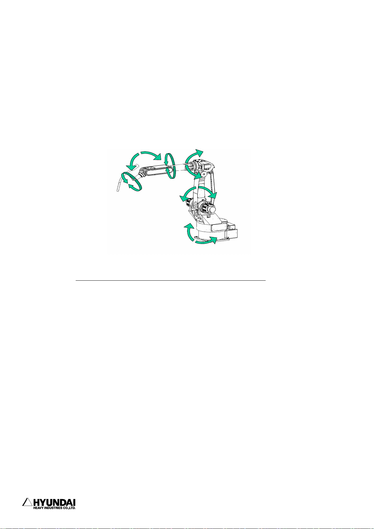
2. Basic operation
-----------------------------------------------------------------------------------------------
2.3.2 Axis coordinate
On the state of Motor ON at manual mode, please check the JOG ON LED is lighted or not. When
press down Coordinate system key on teach pendant, if the light is on at axis it can be move
as operation of key. For the operation key, please refer to chart of 2.3.1 JOG operation key.
B(+)
R2(+)
V(Up)
B(-)
R1(+)
R2(-)
V(Down)
R1(-)
H(Front
)
H(Back)
S(Right)
S(Left)
Axis Coord.
-------------------------------------------------------------------------------------2 - 14
Page 65

-----------------------------------------------------------------------------------------------
2. Basic operation
2.3.3 Robot coordinate
On the state of Motor ON at manual mode, please check the JOG ON LED is lighted or not. When
press down Coordinate system key on teach pendant, if the light is on at cartesian it can be
move as operation of key. For the operation key, please refer to chart of 2.3.1 JOG operation
key.
Zr
Zr
Rzr+
Rzr-
Ryr+
Xr
Rxr-
Yr
Ryr-
Rxr+
Xr
Yr
base
Robot Coord.
--------------------------------------------------------------------------------------
2 - 15
Page 66
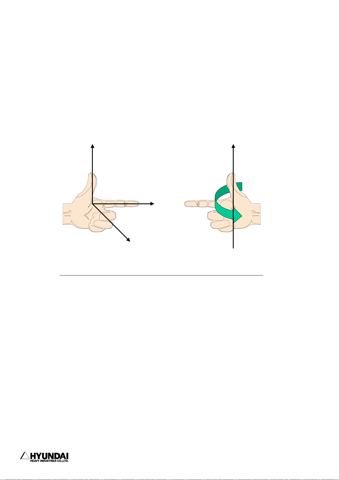
2. Basic operation
-----------------------------------------------------------------------------------------------
Reference
The following figure shows that how to determine the robot coordinate system. Stretch out left
hand's three fingers ; thumb, point finger and middle finger at a right angle. It means that
when the point finger's direction is aligned with Y-direction of robot coordinate, thumb's
direction is pointing Z and point finger's direction is pointing X.
Z
Axis direction
<Reference>
Forward direction
Y
X
+
R
(X,Y,Z)
Rotation direction
+
(X,Y,Z)
-------------------------------------------------------------------------------------2 - 16
Page 67
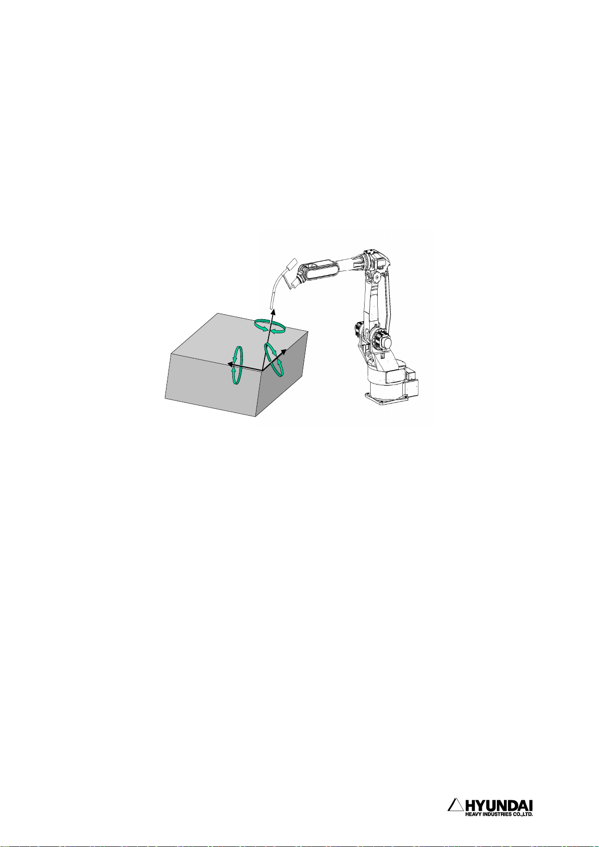
-----------------------------------------------------------------------------------------------
2.3.4 User coordinate
Select user coordinate from 'System'[PF2] → 2 : Controller parameter → 12 : Coordinate
setting → 1 : User coordinate, and then set the selected coordinate. After that play the program
under state of completion key in 'Cond Set'[PF5] → 8 : Select user coordinate, then robot shall
move as following figure.
2. Basic operation
Zu
Rzu
+
Rzu
-
Ryu
Rxu
+
-
Xu
Yu
Rxu
Ryu
Origi n point
-
Support: manual jogging & shi ft
+
User Coor.
--------------------------------------------------------------------------------------
2 - 17
Page 68

2. Basic operation
-----------------------------------------------------------------------------------------------
2.3.5 Tool coordinate
On the state of Motor ON at manual mode, please check the JOG ON LED is lighted or not. When
press down Coordinate system key on teach pendant, if the light is on at tool. it can be move
as operation of key. For the operation key, please refer to chart of 2.3.1 JOG operation key.
Rzt+
Rzt-
Zt
Rxt-
Xt
Rxt+
Origin p oint
Ryt+
support: manual jogging & shift
Ryt-
Yt
Tool coord.(with torch)
It shows that the robot is operating without tool.
Rzt
Rxt
+
-
Rzt
Zt
Xt
Rxt
Ryt
+
Yt
support : manual jogging & shift
+
Ryt
Origin point
-
Tool coord.(without tool)
-------------------------------------------------------------------------------------2 - 18
Page 69

-----------------------------------------------------------------------------------------------
2. Basic operation
2.4 Auto tool setting
You can make the same program to the previous program by calibrating automatically the tool
constant without teaching when the teaching point in the previous program is different from
the previous teaching point resulting in changing, modification of the tool.
You can get angle, length of new tool if executing the function after moving the setting tool
in the step that taught previously. At this time, The position data of the step that is taught
is recorded as the pose data, accurate.
Press 'SYSTEM'[PF2] → 1 : User parameter → 2 : Default Pose then following screen will be
displayed.
14:39:38 ***AUTO TOOL SETg*** A:0 S:4
*) By jogging, place the tool-tip at
the point of reference step, with the
If the pose is not certain, execute
'Angle Setting' after this function.
Program No. = [ 0]
Step No. = [ 0]
Tool No. = [ 0]
Select and Enter number. Press [SET]
>[1 - 999]_
------------------------------------------------------------------------------------- 2 - 19
Page 70

------------------------------------------------------------------------------------------------
3. Service menu
Chapter 3. Service Menu
Contents
━━━━━━━━━━━━━━━━━━━━━━━━━━━━━━━━━━━━━━━━━━━━━
3.1 Monitoring ..................................................... 3 - 4
3.2 Register ...................................................... 3 - 15
3.2.1 XYZ Shift register .................................... 3 - 16
3.2.2 Shift buffers ......................................... 3 - 18
3.2.3 On-line shift register Group .......................... 3 - 20
3.2.4 Palletizing register .................................. 3 - 22
3.2.5 Frequency condition register .......................... 3 - 25
3.2.6 Conveyor data ......................................... 3 - 26
3.3 Variable....................................................... 3 - 28
3.4 Edit program................................................... 3 - 29
3.4.1 Modify writing condition totally ...................... 3 - 30
3.4.2 Modify speed in record totally ........................ 3 - 31
3.4.3 Modify position in record totally ..................... 3 - 32
3.4.4 Step copy ............................................ 3 - 34
3.4.5 Step reverse copy ..................................... 3 - 36
3.4.6 Edit program in running (Hot edit) ................... 3 - 38
3.5 File management................................................ 3 - 43
3.5.1 Internal memory file name ............................ 3 - 44
3.5.2 Program first data .................................... 3 - 45
3.5.3 Internal program axis no. ............................. 3 - 46
3.5.4 Rename ............................................... 3 - 47
3.5.5 Copy.................................................. 3 - 51
3.5.6 Delete ............................................... 3 - 53
--------------------------------------------------------------------------------------- 3 - 1
Page 71

3. Service menu
━━━━━━━━━━━━━━━━━━━━━━━━━━━━━━━━━━━━━━━━━━━━━━━
3.5.7 Protect .............................................. 3 - 55
3.5.8 Storage media format ................................. 3 - 58
3.5.9 Save/Load (SRAM Card) ................................ 3 - 59
3.6 Program conversion ............................................ 3 - 61
3.6.1 Coordinate transformation ............................ 3 - 62
3.6.2 Mirror Image ......................................... 3 - 64
3.6.3 Off-Line XYZ shift .................................. 3 - 67
3.7 System checking .............................................. 3 - 69
3.7.1 System version ....................................... 3 - 70
3.7.2 Run time ............................................ 3 - 71
3.7.3 Diagnosis of troubles................................. 3 - 74
3.7.4 Error logging ....................................... 3 - 76
3.7.5 Stop history ........................................ 3 - 78
3.7.6 Operation history ................................... 3 - 80
3.8 Date setting (Date, Time) .................................... 3 - 81
---------------------------------------------------------------------------------------3 - 2
Page 72

------------------------------------------------------------------------------------------------
3. Service menu
Chapter 3 Service Menu
When you press the "Service [PF1]" on the Manual or Auto Mode. the following display
contents appear.
14:39:38 ** Service contents ** A:0 S:4
1: Monitoring [R245]
2: Register setting
3: Variables
4: Program modify
5: File manager
6: Program conversion
7: System checking
8: Date setting(Day, Time)
Use [Number]/[Up][Down] and press [SET].
>
Previous Next
--------------------------------------------------------------------------------------- 3 - 3
Page 73

3. Service menu
━━━━━━━━━━━━━━━━━━━━━━━━━━━━━━━━━━━━━━━━━━━━━━━
3.1 Monitoring
Outline
It displays encoder value of each axis, degrees of angle, coordinates value data
in/output condition. It is same as the code "R245 : Monitor mode selection"
Screen display
14:39:38 *** Monitoring *** A:0 S:4
0: Monitor OFF
1: Axis data
2: Private input
3: Private output
4: DIO( 1 - 24 )
5: DIO( 25 - 48 )
6: DIO( 49 - 72 )
7: DIO( 73 - 96 )
8: DIO( 97 - 120)
9: DIO(121 - 144)
10: DIO(145 - 168)
----------------------------------------
11: DIO(169 - 192)
12: DIO(193 - 216)
13: DIO(217 - 240)
14: DIO(241 - 256)
15: Spot welding input/output monitor
16: Brake slip count
17: DIO Name display
18: Conveyor data(with axis data)
19: Analog data
20: Servo GUN data
21: Palletize register
-------------------------------------- 22: Equalizerless GUN data
23: DSP analog monitor
Use [Number]/[Up][Down] and press [SET].
>
Line Previous Next
---------------------------------------------------------------------------------------3 - 4
Page 74

g
Service Syste
Set
3. Service menu
------------------------------------------------------------------------------------------------
Reference
When you select the "Line[PF1]", you can change the number of lines of monitoring
function on the display screen.
14:39:38 *** Monitoring *** A:0 S:4
How many monitoring lines? [7]
Enter the number of line and press [SET]
>[2 - 7]
Input the number of Line of Monitoring screen display by number key, press [SET].
After you input the number and press the "Complete[PF5]" the display screen returns
back the " Monitoring "
You can see the following display screen when you select the number of Line "2" in
Manual Mode.
14:39:38 *** M A N U A L *** A:0 S:4
T0 G1
PN:100[*]__ S/F=4/0 Sp:100.00
Robot:H120, 6axes, 1steps
S1 MOVE P,S=100%,A=0,T=1
Current Command Angle Coor(mm)
S :040000 040000 0.0de
X= 0.0
>
Service System Rel.WAIT Cond Set
You can see the following display screen when you select the number of Line "5" in
Manual Mode.
14:39:38 *** M A N U A L *** A:0 S:4
T0 G1
PN:100[*]__ S/F=4/0 Sp:100.00
Robot:H120, 6axes, 1steps
S1 MOVE P,S=100%,A=0,T=1
Current Command Angle Coor(mm)
S :040000 040000 0.0deg X= 0.0
H :040000 040000 90.0deg Y= 0.0
V :040000 040000 0.0deg Z= 0.0
R2:040000 040000 0.0deg
>
m Rel.WAIT Cond
--------------------------------------------------------------------------------------- 3 - 5
Page 75

3. Service menu
Service Syste
Set
━━━━━━━━━━━━━━━━━━━━━━━━━━━━━━━━━━━━━━━━━━━━━━━
3.1.0 Monitor OFF
Outline
It cancel the function of Monitoring that you already select.
3.1.1 Axis Data
Outline
It displays present encoder value of each axis, setting encoder value, degrees of
angle, coordinates value. When you press the [Shift] key, it displays the hidden
↓
item.
Screen display
14:39:38 *** M A N U A L *** A:0 S:4
T0 G1
PN:100[*]__ S/F=4/0 Sp:100.00
Robot:H120, 6axes, 1steps
S1 MOVE P,S=100%,A=0,T=1
Current Command Angle Coor(mm)
S :040000 040000 0.0deg X= 0.0
H :040000 040000 90.0deg Y= 0.0
V :040000 040000 0.0deg Z= 0.0
R2:040000 040000 0.0deg
B :040000 040000 0.0deg
R1:040000 040000 0.0deg
>
m Rel.WAIT Cond
3.1.2 Private Input
Outline
It displays the status of the fixed input signal. When you input the present fixed
input signal, it displays reverse indication. When you press the [Shift] key,
↓
it displays the hidden item.
---------------------------------------------------------------------------------------3 - 6
Page 76

3. Service menu
------------------------------------------------------------------------------------------------
Screen display
14:39:38 *** M A N U A L *** A:0 S:4
T0 G1
PN:100[*]__ S/F=4/0 Sp:100.00
Robot:H120, 6axes, 1steps
S1 MOVE P,S=100%,A=0,T=1
<< Private Input Signal >>
Auto/Manual switch Enable switch
Hard limit ARM interference
Overlaod Motor overheat
---------- Motor on(External)
MSHP on MSPR ON
Emergency stop ----------
>
Service System Rel.WAIT Cond Set
3.1.3 Private Output
Outline
It displays the status of the fixed output signal. When you input the present fixed
output signal, it displays reverse indication. When you press the [Shift] key, it
displays the hidden item.
Screen display
14:39:38 *** M A N U A L *** A:0 S:4
T0 G1
PN:100[*]__ S/F=4/0 Sp:100.00
Robot:H120, 6axes, 1steps
S1 MOVE P,S=100%,A=0,T=1
<< Private Output Signal >>
Motors on(LED) --------- MSPR ON MSPR ON
Start(LED) --------- Synthetic Err(LED) Stop(LED)
Hard limit release AUTO mode(Private)
>
3.1.4 DIO( 1 - 24 )
3.1.14 DIO(241 - 256)
Outline
It displays the status of common Input/Output.
--------------------------------------------------------------------------------------- 3 - 7
Page 77
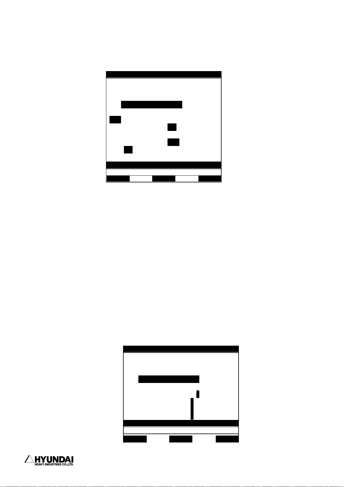
3. Service menu
━━━━━━━━━━━━━━━━━━━━━━━━━━━━━━━━━━━━━━━━━━━━━━━
Screen display
The following screen displays when you select "4;DIO( 1 - 24 )".
14:39:38 *** M A N U A L *** A:0 S:4
T0 G1
PN:100[*]__ S/F=4/0 Sp:100.00
Robot:H120, 6axes, 1steps
S1 MOVE P,S=100%,A=0,T=1
<< General I/O Signal >>
I1 I2 I3 I4 I5 i6 I7 I8
I9 I10 i11 I12 i13 I14 I15 I16
I17 I18 I19 I20 I21 I22 I23 I24
O1 o2 O3 O4 O5 O6 o7 O8
O9 o10 O11 O12 O13 O14 O15 O16
O17 O18 O19 O20 o21 O22 O23 O24
>
Reference
"System"[PF2] -> 2. Controller parameter -> 1. Setting input & output signal -> 7:
Input signal assigning, 6: Output signal assigning Allocated signal displays small
letter.
※ Not allocated signal : O5 , I14
※ Allocated signal : o5 , i14
3.1.15 Spot welding Input/Output Monitor
Outline
It displays the status of the welding condition signal, GUN signal, MX signal,
Welding finish Input signal in spot welding..
Screen display
14:39:38 *** M A N U A L *** A:0 S:4
T0 G1
PN:100[*]__ S/F=4/0 Sp:100.00
Robot:H120, 6axes, 1steps
S1 MOVE P,S=100%,A=0,T=1
<< Spot Welding I/O >>
WELDg-Cond output = 0 1 2 3 4 5 6 7
Gun output = 1 2
MX output = 1 2
WI input = 1 2
>
Service System Rel.WAIT Cond Set
---------------------------------------------------------------------------------------3 - 8
Page 78
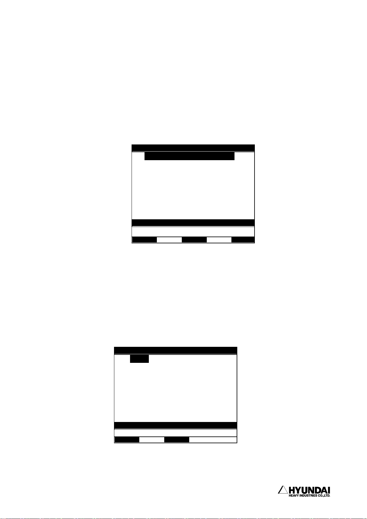
]/[Up][
3. Service menu
------------------------------------------------------------------------------------------------
3.1.16 Break Slip Count
Outline
You can select/ display the slip count value over the range and initialize it when
you use in stud welding(Break ON type). You must select "System[PF2]" -> 5. System
format -> 4: Setting usage of the robot, set the menu Stud in GUN1 or GUN2.
Screen display
14:39:38 * Slip count display * A:0 S:4
1: Slip count display/setting
2: Slip count reset
Use [Number
Down] and press [SET].
>
3.1.16.1 Slip Count display/setting
Outline
It displays the number of the break slip count in each axis and it is set the slip
count by user. You must select " System[PF2] -> 5. System format -> 4: Setting usage
of the robot, set the menu Stud in GUN1 or GUN2.
Screen display
14:39:38 * Slip count display * A:0 S:4
S: [ 0] H :[ 0]
V: [ 0] R2:[ 0]
B: [ 0] R1:[ 0]
Enter number and press [SET]
>[0 - 65535]
--------------------------------------------------------------------------------------- 3 - 9
Page 79

3. Service menu
]/[Up][
━━━━━━━━━━━━━━━━━━━━━━━━━━━━━━━━━━━━━━━━━━━━━━━
Operation method
Input the number of slip count by number key and press the [SET]. When the slip count
of each axis are input, press the "Complete[PF5]"
3.1.16.2 Slip Count reset
Outline
It initialize slip count in all axis.
Screen display
The following message displays on the screen.
Clear to slip count? [YES/NO]
>
Operation method
When you select (YES), the slip count of all axis are 0 and initializes. When you
select (NO), it cancels.
3.1.17 DIO name display
Outline
It confirms the Input/Output signal name. Monitoring of DIO name display is
"System"[PF2] -> 2. Controller parameter -> 1. Setting input & output signal -> 9.
Editing DIO names, Write DIO name in DIO name edit.
Screen display
14:39:38 *** DIO name *** A:0 S:4
1: Page 1
2: Page 2
3: Page 3
4: Page 4
Use [Number
Down] and press [SET].
>
----------------------------------------------------------------------------------------
3 - 10
Page 80

Service Syste
Set
3. Service menu
------------------------------------------------------------------------------------------------
Operation method
When you select the page you want, the following screen displays the DIO name
monitoring.
14:39:38 *** M A N U A L *** A:0 S:4
T0 G1
PN:100[*]__ S/F=4/0 Sp:100.00
Robot:H120, 6axes, 1steps
S1 MOVE P,S=100%,A=0,T=1
<< DIO Name >>
I1 : Clamp check O1 : Clamp ON
I2 : Collition sens O5 : Program END
I8 : Ext. stop O8 : Emergency
I25 : Safety plug O10 :
________________ ________________
>
m Rel.WAIT Cond
3.1.18 Conveyor Data (Included axis data)
Outline
When you use the conveyor, it displays the present encoder value of each axis, setting
encoder value, angle, coordinates, conveyor pulse count, conveyor register, conveyor
speed. Monitoring of Axis & Conveyor is "System"[PF2] ->5. System format -> 2.
Selecting type of the robot select and effective to use conveyor.
Screen display
14:39:38 *** M A N U A L *** A:0 S:4
T0 G1
PN:100[*]__ S/F=4/0 Sp:100.00
Robot:H120, 6axes, 1steps
S1 MOVE P,S=100%,A=0,T=1
Current Command Angle Coor(mm)
S :040000 0400C0 0.0deg X= 0.0
H :040000 0400C0 90.0deg Y= 0.0
V :040000 0400C0 0.0deg Z= 0.0
R2 :040000 0400C0 0.0deg CP= 12345
B :040000 0400C0 0.0deg CR= 500.7
R1 :040000 0400C0 0.0deg CS= 100.0
>
Service System Rel.WAIT Cond Set
--------------------------------------------------------------------------------------- 3 - 11
Page 81
3. Service menu
Service Syste
Set
━━━━━━━━━━━━━━━━━━━━━━━━━━━━━━━━━━━━━━━━━━━━━━━
3.1.19 Analog Data
Outline
It displays the input voltage, output voltage, speed of analog output for analog
port.
Screen display
14:39:38 *** M A N U A L *** A:0 S:4
T0 G1
PN:100[*]__ S/F=4/0 Sp:100.00
Robot:H120, 6axes, 1steps
S1 MOVE P,S=100%,A=0,T=1
<< Analog signal I/O >>
Port1 Port2 Port3 Port4
Input(V) -12.0 -12.0 -12.0 -12.0
Output(V) 0.0 0.0 0.0 0.0
=> Proportional speed(mm/s): 0.0
>
3.1.20 Servo GUN Data
Outline
When you use the servo GUN, it displays the encoder value, current, welding force
data for servo GUN, real inspection welding force in welding operation, distance
and wear amount between moving electrical pole and fixed electrical pole. You must
register the servo gun for additional axis for Servo gun axis data monitoring.
Screen display
14:39:38 *** M A N U A L *** A:0 S:4
T0 G1
PN:100[*]__ S/F=4/0 Sp:100.00
Robot:H120, 6axes, 1steps
S1 MOVE P,S=100%,A=0,T=1
<Servo GUN1 Data> Current Command
Axis encoder => 00000000 : 00000000
Axis current => 0.00 : 0.00
Squeeze force => 0.00 : 350.00
(Realistic squeeze force): 0.00
Length => 0.00 : 0.00
Consumption=>move: 0.00 fixed: 0.00
>
m Rel.WAIT Cond
----------------------------------------------------------------------------------------
3 - 12
Page 82

3. Service menu
------------------------------------------------------------------------------------------------
3.1.21 Palletize Register
Outline
It displays the status of palletizing operation. It displays the status of
palletizing, pattern register number, counter,number of workpieces, and size of
workpiece. You must register the Palletizing for GUN2 for palletizing data monitoring.
"System"[PF2] -> 5. System format -> 4. Setting usage of the robot: GUN2: Palletizing
Screen display
14:39:38 *** M A N U A L *** A:0 S:4
T0 G1
PN:100[*]__ S/F=4/0 Sp:100.00
Robot:H120, 6axes, 1steps
S1 MOVE P,S=100%,A=0,T=1
SFT+[<-][->]<Pa01> <Pa02> <Pa03> <Pa04>
Work state : ON OFF OFF OFF
Pattern Reg : 1 0 0 0
Counter : 20 0 0 0
Total No. : 80 0 0 0
Work size(X): 1000.0 0.0 0.0 0.0
Work size(Y): 1000.0 0.0 0.0 0.0
>
Service System Rel.WAIT Cond Set
Reference
⑴ When you press the [Shift] ↓, [Shift] → key, it displays the hidden item.
3.1.22 Equalizeless GUN Data
Outline
When you use the eqaulizeless GUN, it displays the welding condition no., welding
force , 2-stroke data, in/output of welding- finish and wear amount of fixed
electrical pole. and fixed electrical pole. You must register the equalizeless gun
for GUN1 or GUN2 for equalizeless gun data monitoring. "System"[PF2] --> 5. System
format -> 4. Setting usage of the robot : GUN1 or GUN2: Spot and Air-GUN1 or Air-GUN
2 : EQ'less
--------------------------------------------------------------------------------------- 3 - 13
Page 83

3. Service menu
━━━━━━━━━━━━━━━━━━━━━━━━━━━━━━━━━━━━━━━━━━━━━━━
Screen display
14:39:38 *** M A N U A L *** A:0 S:4
T0 G1
PN:100[*]__ S/F=4/0 Sp:100.00
Robot:H120, 6axes, 1steps
S1 MOVE P,S=100%,A=0,T=1
<Equalizerless GUN Data> Gun1 Gun2
Welding CND number(M33) = 002 xxx
Squeeze output = ON OFF
Two step stroke output = ON OFF
Welding compete input = ON OFF
Fixed tip consumption = 0.00 0.00
>
---------------------------------------------------------------------------------------3 - 14
Page 84

]/[Up][
3. Service menu
------------------------------------------------------------------------------------------------
3.2 Register
Outline
It displays / changes the XYZ shift register, Shift buffer, On line shift register group,
Palletize register, Frequency condition register.
Screen display
14:39:38 *** Register *** A:0 S:4
1: XYZ shift register
2: Shift buffer [R162]
3: ON-line shift register group
4: Palletizing register
5: Frequency condition register[R 18]
6: Conveyor data
Use [Number
Down] and press [SET].
>
--------------------------------------------------------------------------------------- 3 - 15
Page 85

3. Service menu
━━━━━━━━━━━━━━━━━━━━━━━━━━━━━━━━━━━━━━━━━━━━━━━
3.2.1 XYZ Shift Register
Outline
It is keeping the tool angle of point that is already taught and a parallel movement
in XYZ dimension. XYZ register reserves 3 dimension of shift data.
Screen display
14:39:38 *** Register *** A:0 S:4
# XYZ shift register
X=[ 0.0] Y=[ 0.0] Z=[ 0.0]mm
Select and Enter number. Press [SET]
>[-3000.0 - 3000.0]
Operation method
After moving the cursor to changing the position, and press [SET] after inputting
the numeric value with a numeric key.
If setting is ended, press 'Complete"[PF5] and the data is saved. If press 'Cancel"
and it is canceled.
Reference
⑴ Playback of XYZ shift function
You must set the length in the direction of X,Y, and Z axis to the GUN -end exactly
because translation is keeping the GUN angle.
⑵ Application of XYZ shift function
In case of translating the work parallel from the points A, B, C and D to the points
a, b, c and d.
---------------------------------------------------------------------------------------3 - 16
Page 86

3. Service menu
------------------------------------------------------------------------------------------------
Z축
CD
B
A
X축
c
b
d
a
축
Y
--------------------------------------------------------------------------------------- 3 - 17
Page 87

3. Service menu
━━━━━━━━━━━━━━━━━━━━━━━━━━━━━━━━━━━━━━━━━━━━━━━
3.2.2 Shift buffers
Outline
It is a parallel movement with keeping up the tool angle that already taught.
Screen display
14:39:38 *** Register *** A:0 S:4
1. Shift buffer for robot coordinate
X=[ 0.0] Y=[ 0.0] Z=[ 0.0]mm
AX=[ 0.00] AY=[ 0.00] AZ=[ 0.00]dg
2. Shift buffer for tool coordinate
X=[ 0.0] Y=[ 0.0] Z=[ 0.0]mm
AX=[ 0.00] AY=[ 0.00] AZ=[ 0.00]dg
Select and Enter number. Press [SET]
>[-3000.0 - 3000.0]
Reference
(1) Parallel movement shift
When the point of A, B, C, D and the points of a, b, c, d is a parallel movement
relationship between its two positions. If playback to a position of a, b, c and
d from the program of A, B, C and D with keeping up regularly the tool angle to a
extent of different between the point and the point A from the external.
A
B
D
C
a
b
d
c
(2) Angle calibration shift
A parallel movement shift is a parallel movement with preserving the tool angle but
an angle calibration shift make a shift while calibration correctly the tool angle
on the basis of a deviating angle in the robot coordination system from the external.
It can be playback regularly what is the tool angle for workpiece "A" is the point
"c" as is the tool angle for workpiece "a" to the point "c".
---------------------------------------------------------------------------------------3 - 18
Page 88

3. Service menu
------------------------------------------------------------------------------------------------
A
b
B
C
work A
작업물A
c
work a
작업물a
--------------------------------------------------------------------------------------- 3 - 19
Page 89
3. Service menu
]/[Up][
━━━━━━━━━━━━━━━━━━━━━━━━━━━━━━━━━━━━━━━━━━━━━━━
3.2.3 On-line shift register Group
Outline
On-line shift register group is a register that is set each axis length the palletize
turning number, shift data to be received from the external unit. There are total 8
units. It can be set double register.
Screen display
14:39:38 *** Register *** A:0 S:4
1: ON-line shift register 1
2: ON-line shift register 2
3: ON-line shift register 3
4: ON-line shift register 4
5: ON-line shift register 5
6: ON-line shift register 6
7: ON-line shift register 7
8: ON-line shift register 8
Use [Number
Down] and press [SET].
>
Operation method
Select register group to set. If register group 1 selected, it displays as follow;
Screen description
Request port No. : Input the number of serial port to be inputted from vision equipment
Input value : If the shift value from vision equipment inputted and changed position
data, it changes to "1".
14:39:38 *** Register *** A:0 S:4
# On-line shift register group
[Register1]
Request port No.=[0] Input state=[0]
X=[ 0.0] Y=[ 0.0] Z=[ 0.0]mm
AX=[ 0.00] AY=[ 0.00] AZ=[ 0.00]dg
Select and Enter number. Press [SET]
>[0 - 2]
---------------------------------------------------------------------------------------3 - 20
Page 90

3. Service menu
------------------------------------------------------------------------------------------------
Reference
If set the on-line shift register clear as <ENBL>, from "Cond Set[PF5] -
AppliCnd[PF1] - 7. Shift register clear" the value of on-line shift register shall
be cleared to '0'.
--------------------------------------------------------------------------------------- 3 - 21
Page 91

3. Service menu
]/[Up][
━━━━━━━━━━━━━━━━━━━━━━━━━━━━━━━━━━━━━━━━━━━━━━━
3.2.4 Palletizing register
Outline
It can be set freely the content of a palletizing register.
It can be selected GUN2 from "System"[PF2] -> 5. System format -> 4. Setting usage of
the robot.
Screen display
14:39:38 *** Register *** A:0 S:4
1: Palletizing register
2: Palletizing preset
3: Palletizing reset
Use [Number
Down] and press [SET].
>
3.2.4.1 Palletizing Register
Outline
Set manually the shift data for palletizing.
Screen display
14:39:38 *** Register *** A:0 S:4
# Palletizing register
1. Palletize shift data
X=[ 0.0] Y=[ 0.0] Z=[ 0.0]mm
AX=[ 0.00] AY=[ 0.00] AZ=[ 0.00]dg
2. Picking up shift data
X=[ 0.0] Y=[ 0.0] Z=[ 0.0]mm
Select and Enter number. Press [SET]
>[-3000.0 - 3000.0]
---------------------------------------------------------------------------------------3 - 22
Page 92

3. Service menu
------------------------------------------------------------------------------------------------
Screen description
Palletize Shift Data : Input shift data for palletizing.
Picking up Shift Data : Input shift data when lifting work piece.
※ To save changed data, press 'Complete'[PF5]. If press, [CANCEL], the data shall not
be saved
3.2.4.2 Palletizing Preset
Outline
Preset the start number of the palletizing workpiece in advance.
It is the function to start robotic palletizing, under the state of pallet No.
palletizing pattern register No. and start No. are completed set by user.
Screen display
14:39:38 *** Register *** A:0 S:4
# Palletizing preset
Palletize pallet No = [ 0]
Palletize pattern register No. = [ 0]
Start count = [ 0]
Select and Enter number. Press [SET]
>[1 - 16]
Screen description
Palletize Pallet No : The number of pallet which will start work.
Palletize Pattern Register No. : Input number of pattern register which will start
work.
Start Count : When it start work, input the counted number of workpiece among the
total number of workpiece on the current pallet.
--------------------------------------------------------------------------------------- 3 - 23
Page 93

3. Service menu
━━━━━━━━━━━━━━━━━━━━━━━━━━━━━━━━━━━━━━━━━━━━━━━
3.2.4.3 Palletizing Reset
Outline
Reset the value of the counter, palletizing register forcibly.
Operation method
If select "Palletizing Reset" item, it will be appeared on the screen as followings
Input the palletize pallet number.(1-16)
>[1 - 16]
If setting is ended, press [SET] key, it will be appeared on the screen as followings
End palletizing? [YES/NO]
>
If press [YES] key, it initialize the palletizing information, or press [NO] to
cancel the work to do.
---------------------------------------------------------------------------------------3 - 24
Page 94

3. Service menu
------------------------------------------------------------------------------------------------
3.2.5 Frequency condition register
Outline
It sets freely the content of frequency condition register.
For example, when use those functions such as Step jump, Step call, Step return,
Function assigned step jump, Program call, Program jump, Function jump, Target program
call, etc. it compares with the value of frequency condition register to decide whether
continue work or not.
Screen display
14:39:38 *** Register *** A:0 S:4
# Frequency condition register counter
1=[ 0] 2=[ 0] 3=[ 0] 4=[ 0]
5=[ 0] 6=[ 0] 7=[ 0] 8=[ 0]
9=[ 0] 10=[ 0] 11=[ 0] 12=[ 0]
13=[ 0] 14=[ 0] 15=[ 0] 16=[ 0]
Select and Enter number. Press [SET]
>[0 - 255]
Operation method
After moving the cursor to changing position with direction key and press [SET] key
after inputting a numeric value with a numeric key.
If press 'End'[PF5] key, changed data shall be stored. If press [CANCEL] key, the
inputted data shall be cleared.
--------------------------------------------------------------------------------------- 3 - 25
Page 95

3. Service menu
]/[Up][
━━━━━━━━━━━━━━━━━━━━━━━━━━━━━━━━━━━━━━━━━━━━━━━
3.2.6 Conveyor Data
Outline
You can set the CR parameter and simulation speed for conveyor simulation and you can
check the conveyor data manual reset or quantity of workpiceses inline. You can set
the conveyor data when you select "System"[PF2] -> 5. System format -> 2. Selecting
type of the robot and select the Conveyor synchronization = <ON>.
Screen display
14:39:38 *** Register *** A:0 S:4
1: Conveyor simulation data [R 45]
2: Conveyor data reset [R 44]
3: Current works' monitoring on C/V
Use [Number
Down] and press [SET].
>
3.2.6.1 Conveyor Simulation Data
Outline
You can set the conveyor register(CR) and conveyor speed(CS) when you play the program
in the simulation.
Screen display
14:39:38 *** Register *** A:0 S:4
# Conveyor simulation data
Rgister (CR) = [ 0.0] mm
Speed (CS) = [ 0.0] mm/sec
Select and Enter number. Press [SET]
>[0.0 - 10000.0]
---------------------------------------------------------------------------------------3 - 26
Page 96

3. Service menu
------------------------------------------------------------------------------------------------
Screen Description
Register(CR) : Input the number of conveyor register.
Speed(CS) : Input the number of conveyor speed.
※ If press 'Complete'[PF5] key, changed data shall be stored. If press [CANCEL] key,
the inputted data shall be cleared.
3.2.6.2 Conveyor Data Reset
Outline
Initialize the conveyor data register.
Screen display
Conveyor data clear. Continue? [YES/NO]
>
If you select the [YES], then you can initialize the conveyor data, and if you select
[NO], then cancel it.
3.2.6.3 Monitoring for workpiece numbers on the conveyor
Outline
When there are many workpieces on the conveyor, you can monitor the number of
workpieces.
Screen display
14:39:38 *** Register *** A:0 S:4
Works entered the CV line = [ 3]
>
--------------------------------------------------------------------------------------- 3 - 27
Page 97

3. Service menu
━━━━━━━━━━━━━━━━━━━━━━━━━━━━━━━━━━━━━━━━━━━━━━━
3.3 Variable
Outline
You can check or modify the present data of main variable and sub variable. Please refer
to the "11. Robot Language -> 11.1.3. Variable" for more details.
Screen display
14:39:38*** Var. Monitoring *** A:0 S:4
Select variable type to display.
Global Local
Integer V% LV%
Real V! LV!
String V$ LV$
Pose P LP
Shift R LR
Select Var Type, Press [SET] or [PF5]
>
Operation Method
When you select the variable type by cursor and press the [SET]. The following display
content is for selecting the constant variable type.
14:39:38*** Var. Monitoring *** A:0 S:4
Var. Data Var. Data
V1%=[ 32519] V2%=[ 21961]
V3%=[ 8232] V4%=[ 2130]
V5%=[ 0] V6%=[ 0]
V7%=[ 1] V8%=[ 0]
V9%=[ 8194] V10%=[ 31]
V11%=[ 4100] V12%=[ 0]
V13%=[ 1] V14%=[ 2]
V15%=[ 17828] V16%=[ -320]
V17%=[-14671] V18%=[ 63]
V19%=[-14448] V20%=[ 63]
Select and Enter number. Press [SET]
>
When you input the number of variable by keying the number and press the [SET].
---------------------------------------------------------------------------------------3 - 28
Page 98

]/[Up][
3. Service menu
------------------------------------------------------------------------------------------------
3.4 Edit Program
Select the "Program modify" and then displays as follows.
14:39:38 *** Program modify *** A:0 S:4
1: Condition modify
2: Speed modify
3: Step position modify
4: Step copy
5: Reverse step copy
6: Hot edit
Use [Number
Down] and press [SET].
>
--------------------------------------------------------------------------------------- 3 - 29
Page 99

3. Service menu
━━━━━━━━━━━━━━━━━━━━━━━━━━━━━━━━━━━━━━━━━━━━━━━
3.4.1 Modify writing condition totally
Outline
You modify the condition in record of many steps in one program.
Screen display
14:39:38 ** Condition modify ** A:0 S:4
Program No. =[ 5]
Start step =[ 1] End step =[ 10]
Accuracy = < Const, 0, 1, 2, 3 >
Tool = < Const, 0, 1, 2, 3 >
GUN 1 = < Const, Off, On >
GUN 2 = < Const, Off, On >
MX = < Const, Off, On >
MX2 = < Const, Off, On >
Select and Enter number. Press [SET]
>[1 - 999]
Display content
Program No: It is used to modify the condition in record in step. First value is
present program number. Input the value when you need to modify it.
Start Step: It is the first step to modify the condition in record. First value
of Start Step is set by 1. Input the value when you need to modify it.
End Step: It is the last step to modify the condition in record. First value of
End Step is set by last step number of present program. Input the value when you
need to modify it.
Accuracy, Tool, GUN1, GUN2, MX, MX2: Select the First Step and End Step by your
request.
---------------------------------------------------------------------------------------3 - 30
Page 100

3. Service menu
------------------------------------------------------------------------------------------------
3.4.2 Modify speed in record totally
Outline
You modify the speed in record of many steps in one program.
Screen display
14:39:38** Speed Modification **A:0 S:4
Prog No. : [ 99]
Step :[ 1] To [ 9]
Mode :<Assign,Scale,Alter Unit>
Range:<All,Welding,Air-Cut,PTP,INT-On>
Unit :<mm/sec,cm/min,sec,%>
Spd/Ratio = [ 100.00]
Select and Enter number. Press [SET]
>[1 - 999]
Display content
Program No.: It is used to modify the speed in record. First value is present selected
program number. Input the value when you need to modify it.
Step: It is the step range to modify speed in record. Range value of Step is First
Step to Last Step. Input the value when you need to modify it.
Mode: Determine the mode of speed select
① Assign: Modify the speed in record totally.
② Scale: Modify the % value of speed in present step when the speed and the unit
are same totally.
③ Alter Unit: Modify the unit of speed in record totally.
Range: Determine the range for modifying step
Unit: Modify the unit of speed in Speed Select and Unit Conversion. Modify the %
value in Magnification Select.
Spd/Ratio: Modify the speed in Speed Select, and % value in Magnification Select.
--------------------------------------------------------------------------------------- 3 - 31
 Loading...