

mBFT17,
Operator Manual
multi-path Blue Force Tracker
April 2017


Table of Content
1. OVER VIEW ..................................................................................................................... 5
2. DESCRIPTIONS OF MBFT 17 ............................................................................................ 6
3. DESCRIPTIONS OF BATTERY PACK ASSEMBLY ................................................................. 6
4. OPERATIONAL INSTRUCTIONS ........................................................................................ 7
4.1 P
OWER
ON/OFF ......................................................................................................................... 7
4.2 V
OLUME CONTROL
4.3 S
HORTCUT BUTTON
4.4 LED
4.5 S
4.6 P
4.7 USB P
4.8 GPS A
4.9 I
4.10 C
INDICATOR
ATELLITE
OWER PORT
LED
ORT
..................................................................................................................................... 7
NTENNA
RIDIUM SATELLITE ANTENNA
HARGER ASSEMBLY
........................................................................................................................... 7
.......................................................................................................................... 7
............................................................................................................................... 7
INDICATOR
................................................................................................................. 7
.................................................................................................................................. 7
........................................................................................................................... 7
................................................................................................... 8
................................................................................................................. 8
4.11 PROTECTIVE CASE ................................................................................................................ 8
5. OPERATION PROCEDURE ................................................................................................ 9
5.1 L
OGIN
........................................................................................................................................... 9
5.2 M
AIN MENU
5.3 I
NITIAL USER REGISTRATION
5.4 T
5.5. D
5.6 S
ACTICAL INFORMATION
IAGNOSTICS
ETTING
5.7 C2 M
5.8 C
5.9 E
AMERA
LECTRONIC MAP
............................................................................................................................ 10
................................................................................................... 11
........................................................................................................ 12
........................................................................................................................ 13
................................................................................................................................. 18
ESSAGES
........................................................................................................................ 19
................................................................................................................................. 22
................................................................................................................... 23
6. COMPONENTS .......................................................................................................... 27
7. SPECIFICATIONS ....................................................................................................... 29
8. CERTIFICATION ......................................................................................................... 29

List of figures
Figure 1-1 operational diagram of mBFT17 _______________________________________ 5
Figure 2-1 mBFT17 Assembly __________________________________________________ 6
Figure 3-1 Battery pack assembly _______________________________________________ 6
Figure 5-1Login screen _______________________________________________________ 9
Figure 5-2 main menu & status bar of screen _____________________________________ 10
Figure 5-3Tactical information management screen _______________________________ 12
Figure 5-4 Setting screen ____________________________________________________ 18
Figure 5-5 GPS status screen __________________________________________________ 18
Figure 5-6 C2 message screen _________________________________________________ 19
Figure 5-7 Free format message screen ________________________________________ 20
Figure 5-8 Position Location Report screen ______________________________________ 21
Figure 5-9 Camera screen ____________________________________________________ 22
Figure 5-10 Photo viewer screen ______________________________________________ 22
Figure 5-11 menu bar on the Map _____________________________________________ 23
Figure 5-12 Distance measuring between two points on the map_____________________ 24
Figure 5-13 Location calculation with direction and distance _______________________ 24
Figure 5-14 Set reference point _______________________________________________ 25
Figure 5-15 Hand sketch 1 ____________________________________________________ 25
Figure 5-16Hand sketch 2 ____________________________________________________ 26
Figure 6-1 components of mBFT17 _____________________________________________ 28
***
1. Over view
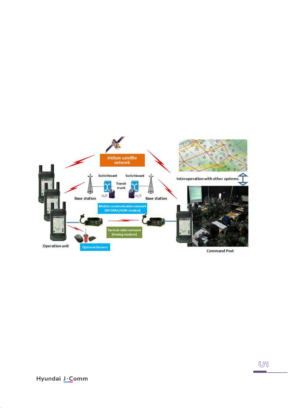
Hyundai J.Comm’s mBFT17, multi-path Blue Force Tracker (hereafter “mBFT17) is an advanced hand
held blue force tracking terminal for users to enables them sharing situational awareness in near real
time by position reporting & C2 messaging.
With integral GPS receiver and electronic map, users can identify its accurate position and share
various tactical messages with geographic location information to other subscribers through integral
iridium and optional communication modems (analog radio modem, WCDMA modem).
Use of mBFT17 and or external WCDMA modem is available after proper subscription procedure with
local representative of Iridium satellite service provider and mobile telecommunication service
provider respectively.
mBFT17 has BLE Bluetooth module to support local area sensor (e.g. heart rate meter, temperaturehumidity sensor). Also it has designed to utilize location based service such as beacon sensors.
Figure 1-1 operational diagram of mBFT17
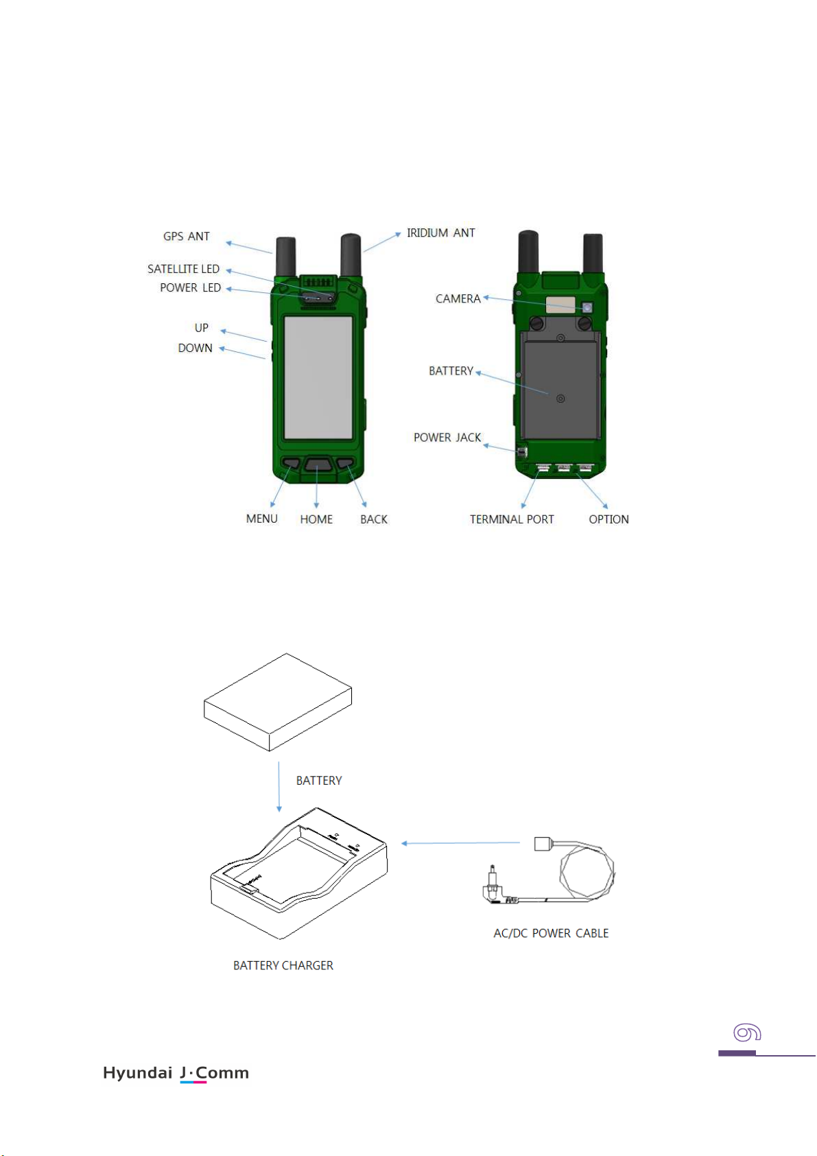
2. Descriptions of mBFT 17
mBFT17 assembly support data communication with Iridium satellite network via integral data
communication modem and it support data communication with WCDMA communication network
and tactical radio network via optional external WCDMA modem and analog radio modem respectively.
Figure 2-1 mBFT17 Assembly
3. Descriptions of Battery pack assembly
Battery pack assembly is rechargeable Lithium-ion Polymer battery with Max 3.7V 5800mAh capacity
and supply power to mBFT17 as installed inside of mBFT17.
Figure 3-1 Battery pack assembly

4. Operational Instructions
4.1 Power ON/OFF
Pressing power button right upper placed over 2 seconds powering mBFT17.
Pressing power button right upper placed over 2 seconds then turn off mBFT17 by click terminate icon
on the LCD
4.2 Volume control
Press volume UP/DOWN button left upper placed to control volume.
4.3 Shortcut button
User can use Menu/home/Cancel button in accordance with its Intended use.
4.4 LED indicator
The status LED lights up green as mBFT17 powered on.
The status LED lights up red while mBFT17 is charging.
The status LED lights up green when the recharging is completed.
4.5 Satellite LED indicator
Satellite LED indicator lights up green as Iridium satellite communication is available.
Satellite LED indicator lights out as Iridium satellite communication is unavailable.
4.6 Power port
mBFT17 can be powered by AC power supply for long time in door use or lack of battery. Connect
cable of AC power supply assembly to power port placed bottom of mBFT17. Once it connected
normally, status bar placed top of LCD display charging icon. In case of charging failure, please reconnect charging cable. Please replace AC/DC adaptor for permanent charging failure.
4.7 USB Port
mBFT17 has USB port to connect it to usb port at computer to download user data and or map data.
Once the cable connected normally, user can identify it display of the computer. USB drive supplied
with mBFT17 should be installed on the computer.
4.8 GPS Antenna
mBFT17 has integral GPS receiver to acquire GPS signal. If mBFT 17 fail to acquire GPS signal after
2minutes later powering on then powering off then re-install GPS antenna.
antenna for permanent failure.
External GPS antenna installation recommended for In door or vehicle operation.
Please replace GPS

4.9 Iridium satellite antenna
mBFT17 has integral Iridium satellite antenna to communicate through Iridium satellite network.
If mBFT 17 fail to receive Iridium satellite signal after 2minutes later powering on then powering off
then re-install Iridium satellite antenna.
External
Iridium satellite
antenna installation recommended for In door or vehicle operation.
Please replace
Iridium satellite
antenna for permanent failure.
4.10 Charger assembly
Rechargeable battery pack assembly of mBFT17 can be charged by charger assembly with high speed.
Install rechargeable battery pack assembly into charger assembly then connect to AC power supply
cable.
The status LED lights up red as connect AC power supply cable while charging.
The status LED lights up green when the recharging is completed.
External
Iridium satellite
antenna installation recommended for In door or vehicle operation.
4.11 Protective case
Protective housing is used exclusively for carrying equipment.
5. Operation procedure
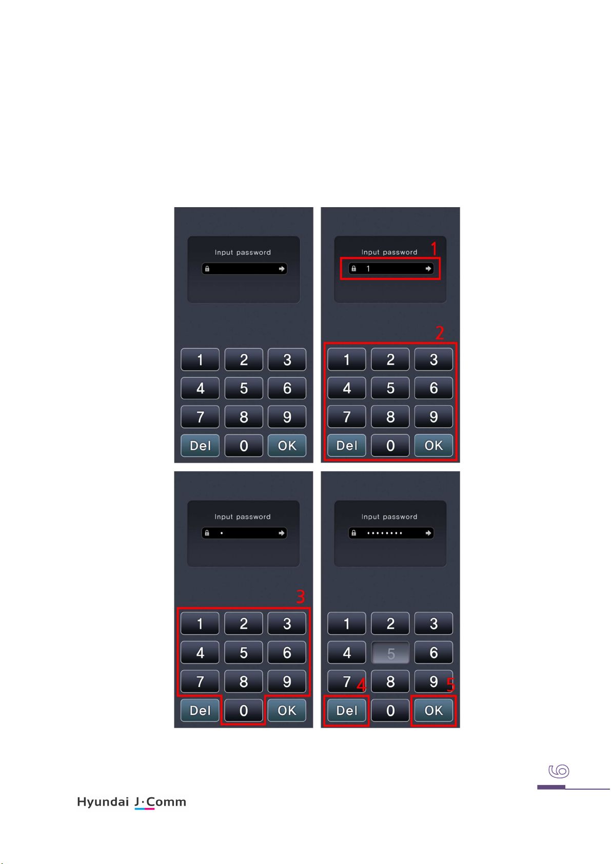
5.1 Login
1. Input password (eight digit)
2. Then Press “OK” ICON
Figure 5-1Login screen

5.2 Main Menu
① Map ICON
② Inspection ICON
③ Setting ICON
④ Tactical ICON
⑤ Message ICON
Figure 5-2
main menu & status bar of screen
⑥ Camera ICON
⑦ User Information Management

⑧ End
⑨ Status Bar
⑩ Position
⑪ Communication Status Bar
⑫ 3G Antenna Bar
⑬ Satellite Antenna Bar
⑭ GPS Antenna Bar
⑮ New Massage Status Bar
⑯ Battery Status Bar
⑰ Time
5.3 Initial user registration
Initial user of mBFT17should input required information into mBFT before use.
A. Basic setting for communication should be done for C2 message
exchange. These items are controlled as list and user should set
these information in Tactical ④
B. To send C2 messages or position reporting, “permanent station”
should be set.
C. Then automatic position reporting, SOS emergency message
should be set. (Refer to automatic position reporting, SOS
emergency message in setting.)

5.4 Tactical Information
User can manage tactical information in the “Tactical Information” menu as follows.
Figure 5-3Tactical information management screen
① Friendly Force Management ICON
② Enemy Force Management ICON
③ Group Management ICON
④ Illegal User Management ICON
⑤ Personnel Equipment Management ICON
⑥ Tactical Graphic Management ICON

5.5. Diagnostics
Inspection menu of mBFT17povides built in test function.
User can verify functionality of SDCard, Battery Gauge, Ethernet Device, GPS module, Iridium
module, FPGA, LED Lamp, Display, Sound, Vibrator, Touch panel and Keypad.
User can verify individual functionality by click left button respectively or verify all at a time by click
“Test all” at bottom.
In normal status each item’s grey window ( ) turn to green ( )
In abnormal status each item’s grey window ( ) turn to red ( )
A. SD card
SC memory Card is main storage of mBFT which has electronic map and C2 messages.
Click button check up SD card.
B. Battery
Click button check up battery then display capacity of the battery on
result window.

C. Ethernet Device
Click button check up Ethernet device.
D. GPS receiver
Click button check up GPS receiver
E. Iridium Communication Module
.
Click button check up Iridium Communication Module
F. FPGA
Click button check up FPGA

G. LED Indicators
Click button check up LED indicators
Cross check between actual LED indicator of mBFT and LED indicators displayed picture in LCD.
H. Display
Click button check up LCD.
Display color changed sequentially from green to red to blue in 1 second.

I. Sound
Click button check up sound
J. Vibration motor
Click button check up vibration motor

K. Touch panel
Click button check up touch panel
Display change as below picture of 1 then check up if each red colored X disappeared by click.
L. Keypad
Click check up key pad.
Keypad check up displays each key on LCD then disappeared by pressing each key.
.

5.6 Setting
This menu set GPS, Iridium communication, WCDMA communication, Ethernet communication.
This is slide-to activation switch of GPS. It is activated by
slide it to right then de-activates by slide it to left. Above
picture show activated GPS.
If user touches GPS line except slide switch, hidden
button as above displayed and it is for checking GPS
status.
GPS Sky view displayed when it enter into GPS status
menu (refer to Figure XX GPS status view).
It displays available and acquired GPS. (Green dot is GPS
and blue dot is GLONASS.)
Figure 5-4 Setting screen
Figure 5-5
GPS status screen
Display shift to CNR view as right above by touching button. The above table displays signal
strengths of receive GPS signal as CNR value.

It is
slide-to activation
to right then de-activates by slide it to left. Above picture show de-activated.
switch of integral Iridium satellite communication module
. It is activated by slide it
It is
slide-to activation
then de-activates by slide it to left. Above picture show de-activated.
switch of external WCDMA communication module
. It is activated by slide it to right
It is slide-to activation switch of integral Ethernet communication module.
right then de-activates by slide it to left. Above picture show de-activated.
If user touches LAN line except slide switch, it enters into Ethernet setting mode to set IP, MASK, GATEWAY and
BCCP.
It is activated by slide it to
5.7 C2 Messages
In C2 message menu of mBFT 17, user can create, edit and manage messages sent or received.
① Create new message
② List of messages (sent/received)
③ Received messages
④ Sent messages
⑤ Button to create free format message
⑥ Button to create position location reporting
⑦ Button to create intelligence information report
⑧ Button to create meteorological report
⑨ Button to create situation report
⑩ Button to create NBC1 report
⑪ Button to create NBC4 report (NBC RECON)
⑫ Button to create Call for fire message
⑬ Button to create Target damage Assessment report
⑭ Button to create Person & Equipment report
⑮ Button to check status of message
⑯ Message select toggle button
⑰ Show types of message
⑲ Select all button
⑳ Delete selected message button
Figure 5-6 C2 message screen

A. Free format message
Click free format message button on the first menu to write free format message.
Scroll menu is fixed permanent station that user belong to.
User can choose recipient of the message by scrolling of button.
Recipient list show registered friendly force and group of Tactical information.
Figure 5-7 Free format message screen
Available transmission path will be scrolled ahead recipient, relevant transmission path should be set
before use.
Free format message consist with title and contents. Once click send button, transmission initiated
then shift to new message write window.
If click save button, mBFT17 store message but not send then shift to new message write window.
User can prioritize the message between normal and immediate.

B. Position Location report
GPS acquired coordination is default.
User can report its position location report to designated recipient and group
User can input MGRS coordinate
manually or choose position on the map
by click position button in case of GPS
failure or user wants to change its
position manually.
Scroll menu is fixed
permanent station that user belong to.
User can choose recipient of the message
By scrolling of button.
Available transmission path will scrolled
ahead recipient, relevant transmission
path should be set before use.
By scrolling of user can
set current status of operation.
Once click send button, transmission
initiated then shift to new message write
window.
If click save button, mBFT17 store
message but not send then shift to new
message write window.
Figure 5-8 Position Location Report screen

5.8 Camera
User can access camera by click “Take Picture” button
mBFT17 has 500M pixel Camera upper back and support dedicated picture viewer application.
Once select photo in photo viewer menu then display shift to
menu to send photo to designated recipient and group.
Scroll menu is fixed permanent station
that user belong to.
User can choose recipient of the photo By scrolling of
button.
Available transmission path will scrolled ahead recipient,
relevant transmission path should be set before use.
User can back to main menu by press back key bottom right
on the mBFT when it display photo viewer menu or send file
menu.
In send file menu, click save button just save message then
Figure 5-9 Camera screen
back to main menu. Transmission of photo take long time so
it operated as background and status bar placed top of menu
show its status of transmission or receiving.
Figure 5-10 Photo viewer screen

5.9 Electronic Map
A. Vertical Contr
ol button in 1, 2 and 3 in
When it enters to map menu, map is displayed as below pictures.
On the map menu, user can move area of map by touch or drag on the LCD.
Vertical control menu consist with “+” and “-“ to magnify or reduce map and toggle key to fix display
or rotate it per moving direction and return key to users current position from up to down.
Bottom menu provide access to message, setting camera and tactical information by click.
red colored squares
○ Button 1 toggled its display on the
map by button 2.
○ “+”. “–“ key in 1 enable
magnitude/reduce displayed map
level
○ Third from top Lock button in 1 is
toggle key between map rotation per
moving direction or rotation of
arrow symbol in 4. When lock
displayed, map doesn’t rotate but
symbol in 4 rotate.
○ Concentric circle symbol in 1
displays distance from arrow symbol.
Figure 5-11 menu bar on the Map

B. Shortcut menu of map screen
Touch then press one point on map screen around 1 second displays shortcut menu (refer to left
picture below)
Figure 5-12 Distance measuring between two points on the map
C. Distance measuring between two points in map
Click Measure Distance button displays distance between selected two points on the map.
Distance measuring performed as shown picture above. If type MGRS coordinate into column of
“from” and “to” it displays distance and direction as shown in right picture above.
At the moment, user can set the points on the map by pressing one point around 1 second.
D. Location calculation with direction and distance
Touch then press one point on map screen around 1 second displays shortcut menu (refer to left
picture below)
Figure 5-13 Location calculation with direction and distance
At the moment, click “Take location” button enables user to acquire coordinate with direction and

distance.
① ② ③ ④ ⑤
Once entered into this menu, point on the map pressed then hold 1 second become entered as a
reference point. (Refer to third picture from left to right in above picture).
Once reference point entered, type distance and bearing then click “Calc” button to display location
with acquired coordinate.
E. Reference point
Touch then press specific point on map screen around 1 second displays shortcut menu (refer to left
picture below)
Figure 5-14 Set reference point
Choose point as above then click “Pointing” button creates reference point on the map and store it.
These created reference point and my position displayed on the map by click target shaped button in
3 of main menu by turns.
F. Hand sketch mode
mBFT17 provide hand sketch mode on the map and entered into this menu by pressing one point on
the map then hold 1 second then choose “add sketch” among popup menu.
Figure 5-15 Hand sketch 1
Figure 5-15 Hand sketch1 shows how to add path on the map.
Click “add sketch” popup menu to use type of sketch in ① of Figure 5-15 Hand sketch 1.

Click “Path” in ② clears popup menu and bottom menu bar as well then “Cancle” and “end” menu
⑦
is on the map as ③. Then User can set a point on the map by touch. ⑤ of Figure 5-15 Hand sketch
1 will be displayed after complete input then press “end”.
At this screen once click “save” will return to normal map screen.
⑥
Figure 5-16Hand sketch 2
Hand sketch support drawing of free line, circle, box, polygon in addition to “Path”.
⑥, ⑦, ⑧, ⑨ in Figure 5-16 Hand sketch 2 shows example of drawing of free line, circle, box and
polygon respectively.
Drawing procedure is similar with Hand sketch 1.
Free line draw as shown in ⑥, it maintain line as long as keep touch on the screen.
Circle draw as shown in ⑦,it forms circle as first touched point become central point then next
clicked point become radius.
In the box drawing as shown in ⑧, it forms quadrangle as first touched point become first point
then dragged point become diagonal point.
⑧
⑨

6. Components
mBFT17 has basic issue items and optional items. Basic issue item includes mBFT17 assembly, battery
pack assembly, charger assembly, AC power supply assembly, protective case assembly, carrying case
assembly and stylus pen assembly.
Descriptions
Q’’’’ty
mBFT17 1
EXTERNAL 3G MODEM 1
BATTERY PACK 2
BATTERY CHARGER 1
AC/DC ADAPTER 1
PROTECTIVE CASE 1
EXTERNAL SATELLITE ANTENNA 1
EXTERNAL GPS ANTENNA 1
ETHERNET CABLE 1
DOWNLOAD CABLE 1
BAG 1
Drawing No Remarks
DETACHABLE
STYLUS PEN 1
SOFTWARE CD 1
OPTION

Figure 6-1 components of mBFT17

7. Specifications
CATEGORY STANDARD Remarks
SIZE 88 (W) X 190 (H) X34 (D) mm
WEIGHT 700g
CPU 1.9GHz/1.3GHz Octa Core DDR3 2GB
OS Android 4.4 (KitKat)
INT. FLASH MEMORY
MICRO SD CARD 128GB MAP
CHARGEING CHARGER / SELF CHARGING DC +5.0V INPUT
BATTERY 5800 mAh NOMINAL 3.7V
OPERATING TIME 10 HOURS
LCD 5.0 INCH / 1280 x 720 AMOLED / C-TOUCH
CAMERA 1300M PIXEL
4GB OS & USER DATA
Except (exclude Antennas and
protrusions)
SENSOR GYRO'/ACCEL'/COMP' 9-AXIS
EXT. PORT USB Data Download
CERTIFICATION MIL-STD-810G/461F/FCC
8. Certification
FCC Part 15 Statement
This device complies with part 15 of the FCC Rules. Operation is subject to the following two
conditions: (1) This device may not cause harmful interference, and (2) This device must
accept any interference received, including interference that can cause undesired operation.
FCC Interference Statement
This equipment has been tested and found to comply with the limits for a Class B digital

device, pursuant to Part 15 of the FCC Rules.
These limits are designed to provide reasonable protection against harmful interference in a
residential installation. This equipment generates, uses, and can radiate radio frequency
energy and, if not installed and used in accordance with the instructions, may cause harmful
interference to radio communications. However, there is no guarantee that interference will
not occur in a particular installation.
If this equipment does cause harmful interference to radio or television reception, which
can be determined by turning the equipment off and on, the user is encouraged to try to
correct the interference by one or more of the following measures:
• Reorient or relocate the radio or television receiving antenna.
• Increase the separation between the computer equipment and receiver.
• Connect the equipment into an outlet on a circuit different from that to which the radio or
television receiver is connected.
• Consult the dealer or an experienced radio television technician for help.
FCC RF Exposure Warning
This equipment complies with FCC radiation exposure limits set forth for an uncontrolled
environment.
SAR Information
mBFT17 is a radio transmitter and receiver. It is designed and manufactured
not to exceed the limits for exposure to radio frequency (RF) recommended
by FCC . These limits are part of comprehensive guidelines and establish permitted levels of
RF energy for the general population. The guidelines include a substantial safety margin
designed to assure the safety of all persons, regardless of age and health.
The exposure guidelines for mobile devices employ a unit of measurement known as the
Specific Absorption Rate or SAR.
The SAR limit is 4.0 watts/kilogram (W/kg) averaged over 10g of tissue. Tests for SAR are
conducted using standard operating positions with the device transmitting at its highest
certified power level in all tested frequency bands.
Use of device accessories and enhancements may result in different SAR values. SAR values
may vary depending on national reporting and testing requirements and the network band.
When using protective case, mBFT17 operates in standby mode or rx only mode under
Conditions of use close to body.
 Loading...