

Page 1
Service Guide
Crawler Excavator
Page 2

INDEX
Ⅰ. Specification Comparisions --------------------------------------------------------------------------------------------- 3
Ⅱ.Hydraulic System -------------------------------------------------------------------------------------------------------------- 7
1.Outline of Hydraulic system ------------------------------------------------------------------------------------------------- 8
2.Hydraulic Symbol --------------------------------------------------------------------------------------------------------------- 9
3.Hydraulic Circuit ---------------------------------------------------------------------------------------------------------------- 15
3-1.Main Circuit
3-2.Pilot Circuit (Crawler Type)
3-3.Pilot Circuit (Wheel Type)
3-4.Oil Return Circuit
4.Main Components --------------------------------------------------------------------------------------------------------------- 19
4-1.Main Control Valve
4-2.Main Pump
4-3.Pilot Circuit
4-4.Swing Motor
4-5.Travel Motor
4-6.Remote Control Valve
4-7.Remote Control Pedal
4-8.Turning Joint
4-9.Safety Valve
4-10.Others
Page1
5.Breaker /Double Function Piping ----------------------------------------------------------------------------------------- 152
5-1.Breaker /Clamshell Piping
5-2.Single Acting Circuit
5-3.Double Acting
5-4.Comparison Table
5-5.Oil Flow / rpm
Ⅲ.Electric & New CAPO System ---------------------------------------------------------------------------------------- 159
1.CAPO System ------------------------------------------------------------------------------------------------------------------- 160
1-1. Power Mode Selection System
1-2. Switches on Joy Stick Lever
Construction Equipment
Page 3

1-3. Monitor Panel (Cluster)
1-4. Communication
1-5. Automatic Deceleration System
1-6. Power Boost System
1-7. Travel Speed Control System
1-8. Automatic Warming Up & Engine Overheat prevention
1-9. Anti - R estart Function
1-10. Location of Solenoid Valves
1-11. Work/Power Mode Selection
1-12. Monitoring Display on Cluster
1-13. Malfunction of Cluster or Mode Sele ction System
1-14. Accel. Actulator
1-15. Engine Speed Sensor (not for excavators with QS-engines)
1-16. Engine rpm control System
1-17. Hydraulic Oil Flow Control system
1-18. Input & Output Signal
1-19. Intake Air Warming up System
1-20. Troubleshooting Guide
2.Electric System --------------------------------------------------------------------------------------------------------------------- 216
2-1. Component Location (Cabin)
2-2. Fuses & Relays
2-3. Continual Circuit
2-4. IG Circuit
2-5. Start Circuit
2-6. Charging Circuit
2-7. Lights Circuit
2-8. Monitoring Circuit
2-9. Wiper & Washer Circuit
Page2
Construction Equipment
Page 4

Ⅰ.Specification Comparisions
Page3
Construction Equipment
Page 5

R140LC-7
Unit
Hyundai Komastu CAT Hitachi
R140-7
PC130-6 312C ZX120
Oper. Weight
Power, SAE net
DIN net
Bucket PCSA
CECE
Engine
Model
Cyl*Bore*Stroke
Displacement
Max. torque
Hydraulic pump LPM
Oper. Pressure
Attachment
Power boost
Travel
Swing
Swing speed
Travel speed
Standard machine
Boom
Arm
Track shoe width
Track gauge
Tumbler distance
Ground pressure
Max traction force
Bucket digging force,SAE
Arm crawd force,SAE
Fuel tank liter
Kg
HP/rpm
PS
cu m
cu m
mm
cc
Kgf.m/rpm
Kg/cm2
rpm
Km/h
m
m
mm
mm
mm
kg/cm2
ton
ton
ton
13980
102/2100
103/2100
0.58
0.5
Cummins
B3.9-C
4*102*120
3920
46.2/1500
2*130
330
360
330
240
13.6
3.3/5.5
4600
2500
600
2000
3000
0.36
13.3
9.27
9.27
270
13050
86/2200
87/2200
Komatsu
S4D102E
4*102*120
3920
1*226
325
325
275
12.0
2.7/3.6/5.5
4600
2500
500
1960
2750
0.41
10.2
8.5
8.5
230 250 250
12200
91/1950
0.5
0.45
CAT
3064-E1T
4250
305
-
350
12.9
3.8/5.5
4650
2500
500
1990
2780
0.4
11.0
12200
85/2100
0.5
0.45
Isuzu
CC-4BG1TC
4329
350
-
13.7
3.4/5.5
2000
500
1990
0.38
Page4
Construction Equipment
Page 6

R160LC-7
Unit
Hyundai Komastu CAT Hitachi
R160LC-7
PC160-6 315C ZX160LC
Oper. Weight
Power, SAE net
DIN net
Bucket PCSA
CECE
Engine
Model
Cyl*Bore*Stroke
Displacement
Max. torque
Hydraulic pump LPM
Oper. Pressure
Attachment
Power boost
Travel
Swing
Swing speed
Travel speed
Standard machine
Boom
Arm
Track shoe width
Track gauge
Tumbler distance
Ground pressure
Max traction force
Bucket digging force,SAE
Arm crawd force,SAE
Fuel tank liter
Kg
HP/rpm
PS
cu m
cu m
mm
cc
Kgf.m/rpm
Kg/cm2
rpm
Km/h
m
m
mm
mm
mm
kg/cm2
ton
ton
ton
17400
116/2100
118/2100
0.70
0.60
Mitsubishi
S6S-DT
4*94*1200
4996
42.5/1500
2*168
330
360
330
240
12.1
3.7/5.6
5100
2600
600
1990
3190
0.42
15.7
12.08
8.35
260
16530
104.5/2100
106/2100
0.58
0.53
Komatsu
SA4D102E
4*102*120
3920
-
276
325
355
355
325
12.0
2.7/4.0/5.5
5150
2600
600
1990
2880
0.44
13.8
12.54
8.393
250 285 280
16000
-
111/2150
0.65
0.55
CAT
3046-E3DT
-
4990
-
350
-
350
10.2
3.4/5.6
5100
2600
500
1990
2880
0.51
-
-
-
15600
-
100/1950
0.6
0.55
Isuzu
A-4BG1TC
-
4329
-
350
-
13.6
3.1/5.3
5100
2580
500
1990
3100
0.46
-
9.2
8.1
Page5
Construction Equipment
Page 7

R210LC-7
Unit
Hyundai Komastu CAT Hitachi
R210LC-7
PC210-6 320B EX200-5
Oper. Weight
Power, SAE net
DIN net
Bucket PCSA
CECE
Engine
Model
Cyl*Bore*Stroke
Displacement
Max. torque
Hydraulic pump LPM
Oper. Pressure
Attachment
Power boost
Travel
Swing
Swing speed
Travel speed
Standard machine
Boom
Arm
Track shoe width
Track gauge
Tumbler distance
Ground pressure
Max traction force
Bucket digging force,SAE
Arm crawd force,SAE
Fuel tank liter
Kg
HP/rpm
PS
cu m
cu m
mm
cc
Kgf.m/rpm
Kg/cm2
rpm
Km/h
m
m
mm
mm
mm
kg/cm2
ton
ton
ton
21700
143/2100
145/2100
0.92
0.8
Cummins
B5.9-C
6*102*120
5880
62.0/1600
2*220
330
360
330
240
12.5
3.4/5.3
5880
2920
600
2390
3650
0.46
21.1
14.84
10.8
320
21570
133/2200
0.86
Komatsu
S6D102E
6*102*120
5880
2*206 2*180 2*185
325
355
355
280
12.4
3.2/4.5/5.5
5700
2930
600
2380
3640
0.45
17.7
15.0
10.1
340 340 310
20518
128/1800
130/1800
0.80
0.70
CAT
3116T
6*105*127
6600
350
350
235
10.7
3.4/5.5
5680
2900
600
2200
3265
0.48
18.1
13.5
10.1
133/1950
135/1950
A-6BG1T
6*105*125
47/1600
18800
0.80
0.70
Isuzu
6494
350
370
350
13.9
3.8/5.5
5680
2910
600
2200
3370
0.43
17.3
12.2
Page6
Construction Equipment
Page 8

Ⅱ.Hydraulic System
Page7
Construction Equipment
Page 9
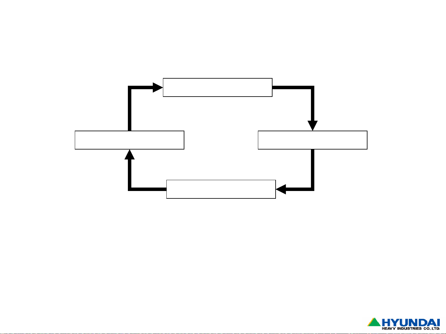
1.Outline of Hyd. System:
-Charecteristic of hydraulic oil : incompressible,automatic lubrication,less friction loss, higher
cooling efficiency,more safety for overload,silent operation,precise control
the equipment to transmit the power by oil flow
Hydraulic Tank
Actuator
Hydraulic Pump
Control Valve
-Hydraulic Tank : Oil Storage
-Hyd. Pump : Create oil flow to transmit the power
-Control Valve : Direction control of actuator
-Actuator : Working device such as cylinder,motor and etc
Cylinder - Inline movement
Motor – Rotating movement
Page8
Construction Equipment
Page 10
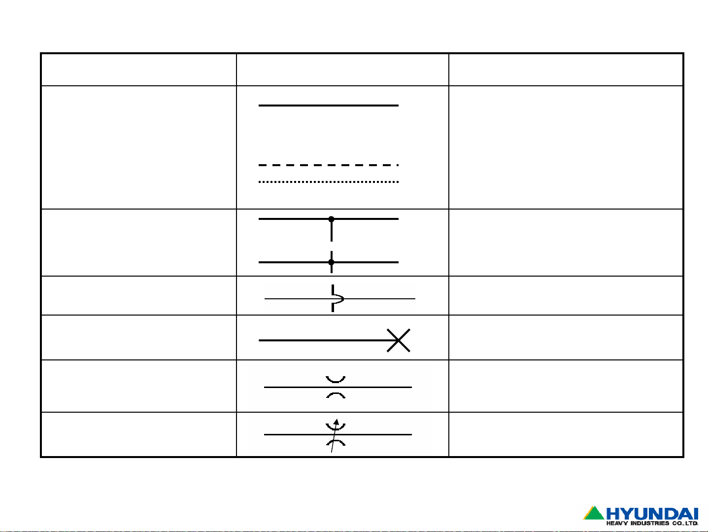
2.Hydraulic Symbol
Component Symbol Explanation
Pipe or hose
-Main line
-Pilot line
-Drain or internal leakage
Orifice Reduced diameter of oil passage to
Color code
-Supply line : red
-Return line : blue
-Suction line : green
-Pilot line : brown
-Drain or internal leakage line : green
Line connected each other : Tee joint or
drilled hole
Line cross over without connection
Line closed or plugged for future usuage
or special purpose
reduce oil flow
Page9
Adjustable orifice Adjustable(or variable)
Construction Equipment
Page 11
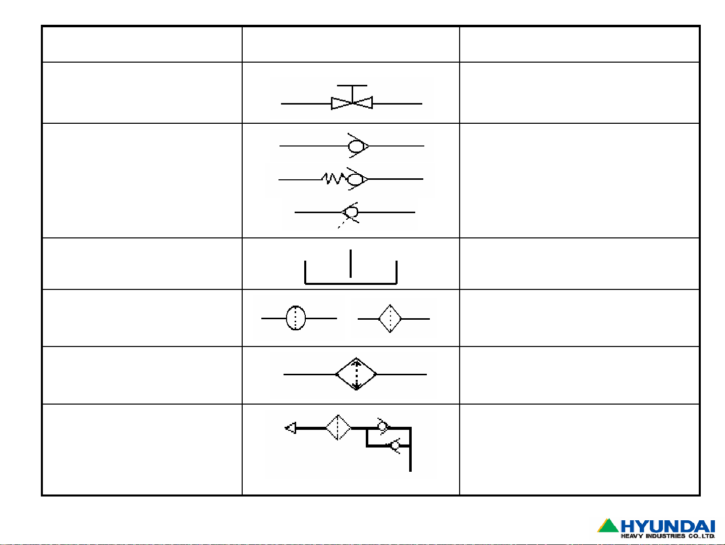
Component Symbol Explanation
Shut off valve
Check valve
-Without spring
Direction controlling device to prevent
reverse flow
-With spring
-Pilot check valve
One check valve & pilot line in one block
Hyd. tank Hyd. oil storage
Filter Filtering all the dirt in hydraulic system
Cooler Exhaust the heat of hyd. oil
Breather Maintain the pressure inside of hydraul i c
tank same as atmospheric pressure
Page10
Construction Equipment
Page 12
Component Symbol Explanation
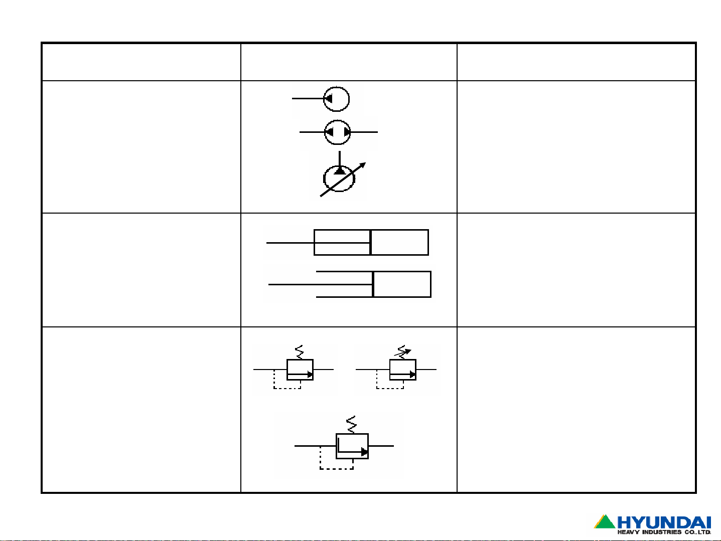
Hydraulic pump
-fixed flow pump
-One direction
-Both direction, depending on rotation of
pump
Discharge amount of pump are flexible
-Variable flow pump
dependng on the pressure at actuator
such as cylinder and motor
Cylinder -Double acting : retract and extend by
direction of oil supply
-Single acting : retract by weight and
extend by oil supply
Pressure control valve
-Relief valve
Safety device to protect hyd. component
such as hose,pipe,cylinder and etc
When the hyd. system overloaded, relief
valve is open and circuit oil go to the tank
through opened passage
Page11
-Regulating valve
Maintain the required pressure all the time
to activate system for transmission clutch
and etc. by increasing decreasing the size
of overflow passage
Construction Equipment
Page 13
Component Symbol Explanation
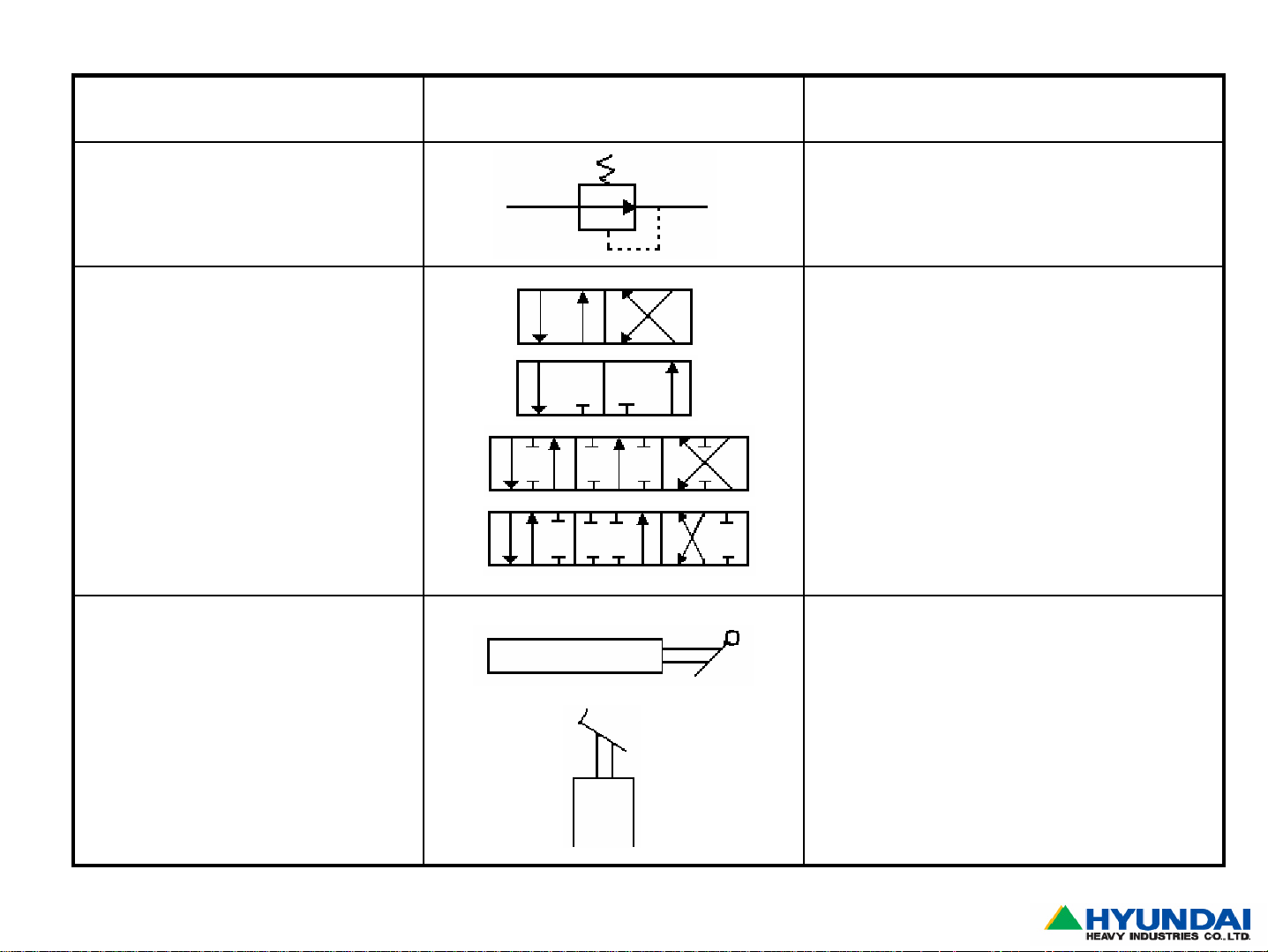
-Reducing vave It is used for low pressure circuit.
When the supplied pressure reach to
required value, supplied oil is cut off
Direction valve
-2 way
-3 way
For double acting
For single acting
Double acting
Controlling method of direction control
valve
Hand control lever
Foot control pedal
Page12
Construction Equipment
Page 14
Component Symbol Explanation
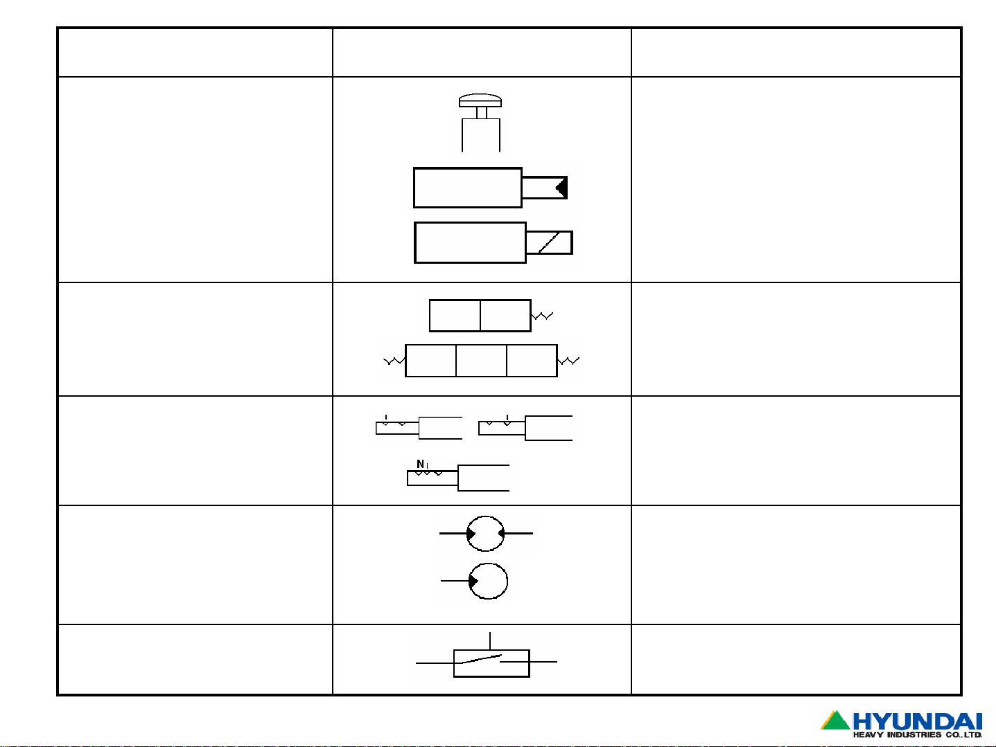
Button control
Hydraulic control by pilot pressure
Electro-magnet control by electricity
Automatic return control by spring tension
Control valve is fixed with selected
direction
Page13
N : neutral position
Motor Rotating device
-Reversible motor
-Irreversible motor : rotate one direction
only
Pressure switch
Construction Equipment
Page 15
Component Symbol Explanation
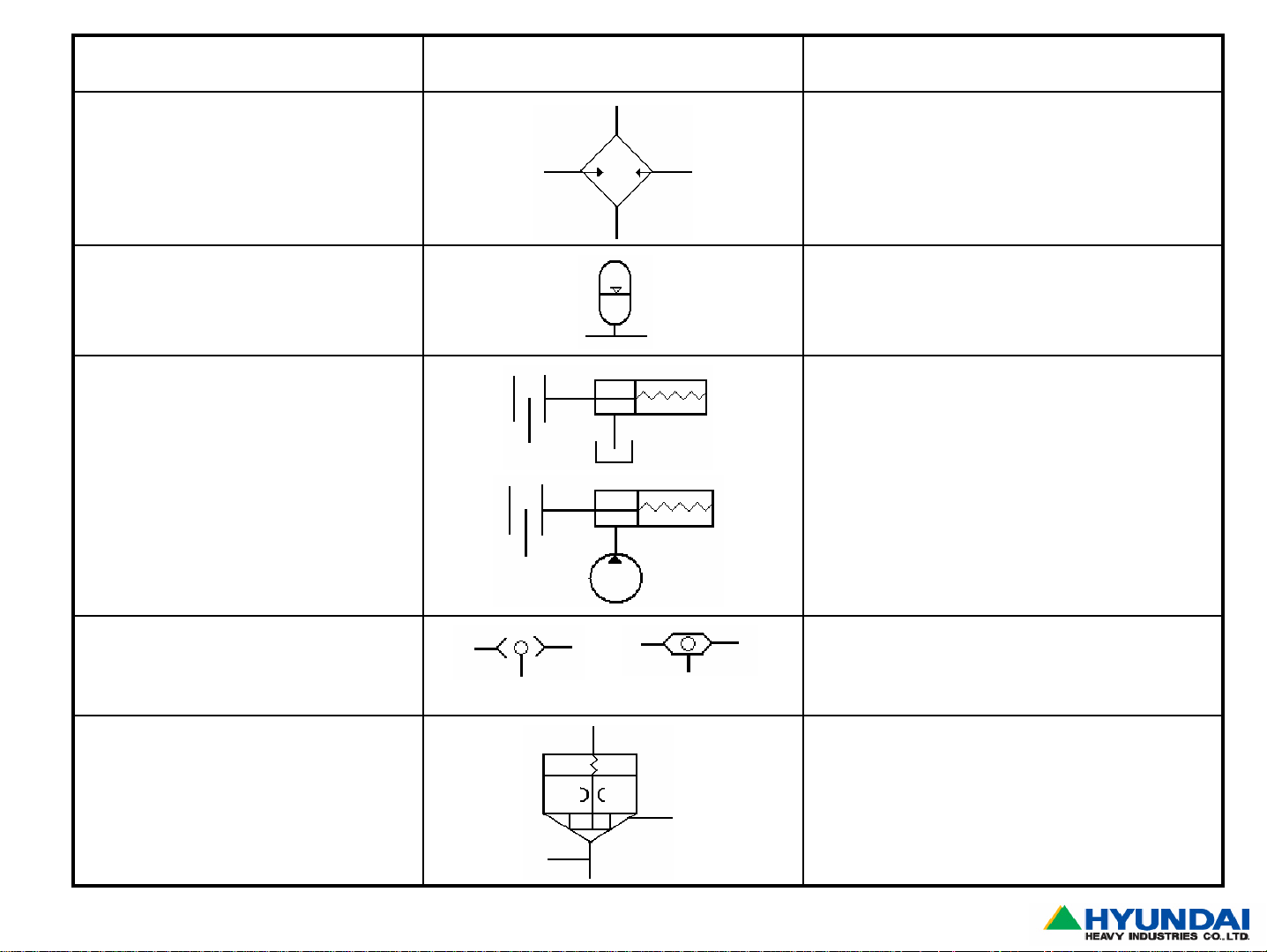
Heater
Accumulator
Brake and clutch Applied by spring force
Released by hydraulic pressure
Page14
Shuttle valve Two check valve in one block
Oil flow achieved by pressure difference
between left & light hand side
Logic valve Is combined with piston and orifice
Area difference operates direction control
valve
Construction Equipment
Page 16
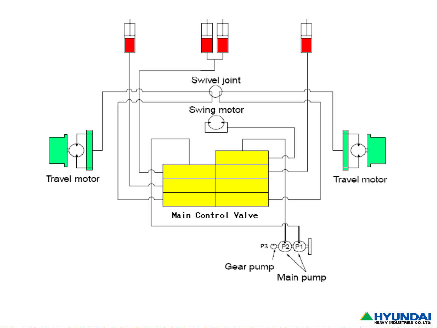
3. Hydraulic Circuit
3-1.Main Circuit
Page15
Construction Equipment
Page 17
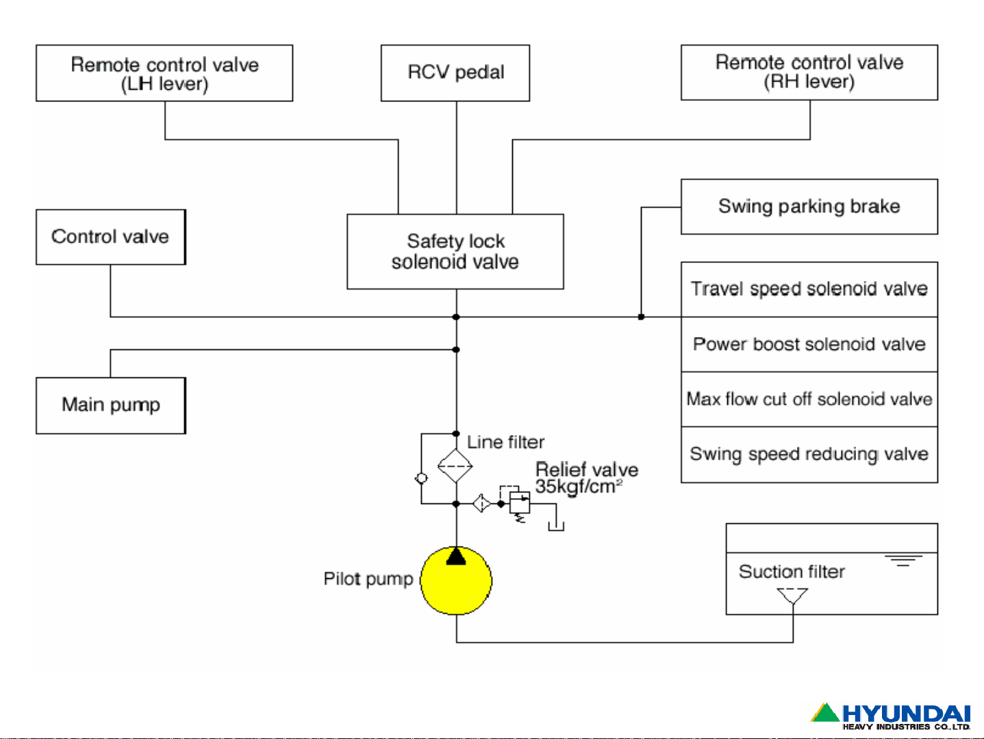
3-2.Pilot Circuit (Crawler Type)
Page16
Construction Equipment
Page 18
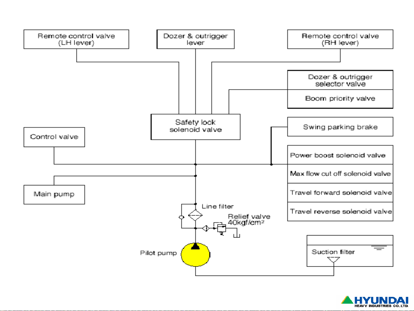
3-3.Pilot Circuit (Wheel Type)
Page17
Construction Equipment
Page 19
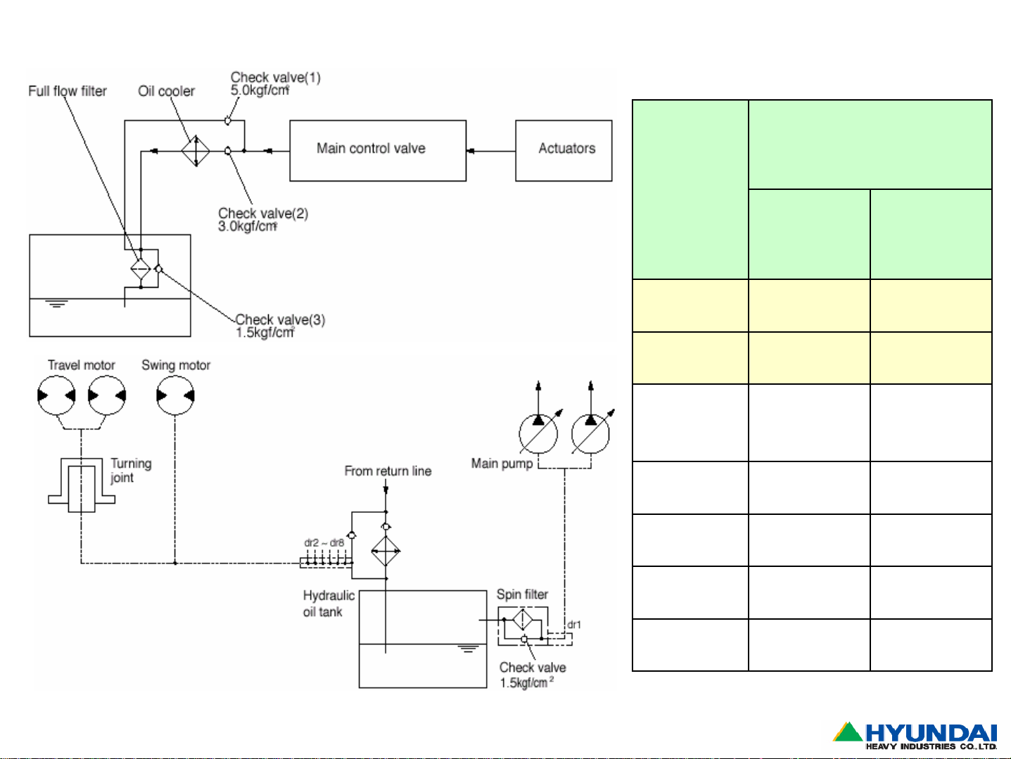
3-4.Oil Return Circuit
Return Pressure (Bar)
Model
Oil Cooler By-pass
R450LC-7
R360LC-7
R320LC-7
R200W-7
R290LC-7A
R210LC-7
R180LC-7
R140LC-7
3
5
3 5
3
5
1.5 3
35
1.5
1.5
3
3
Page18
Construction Equipment
Page 20
4. Main Components
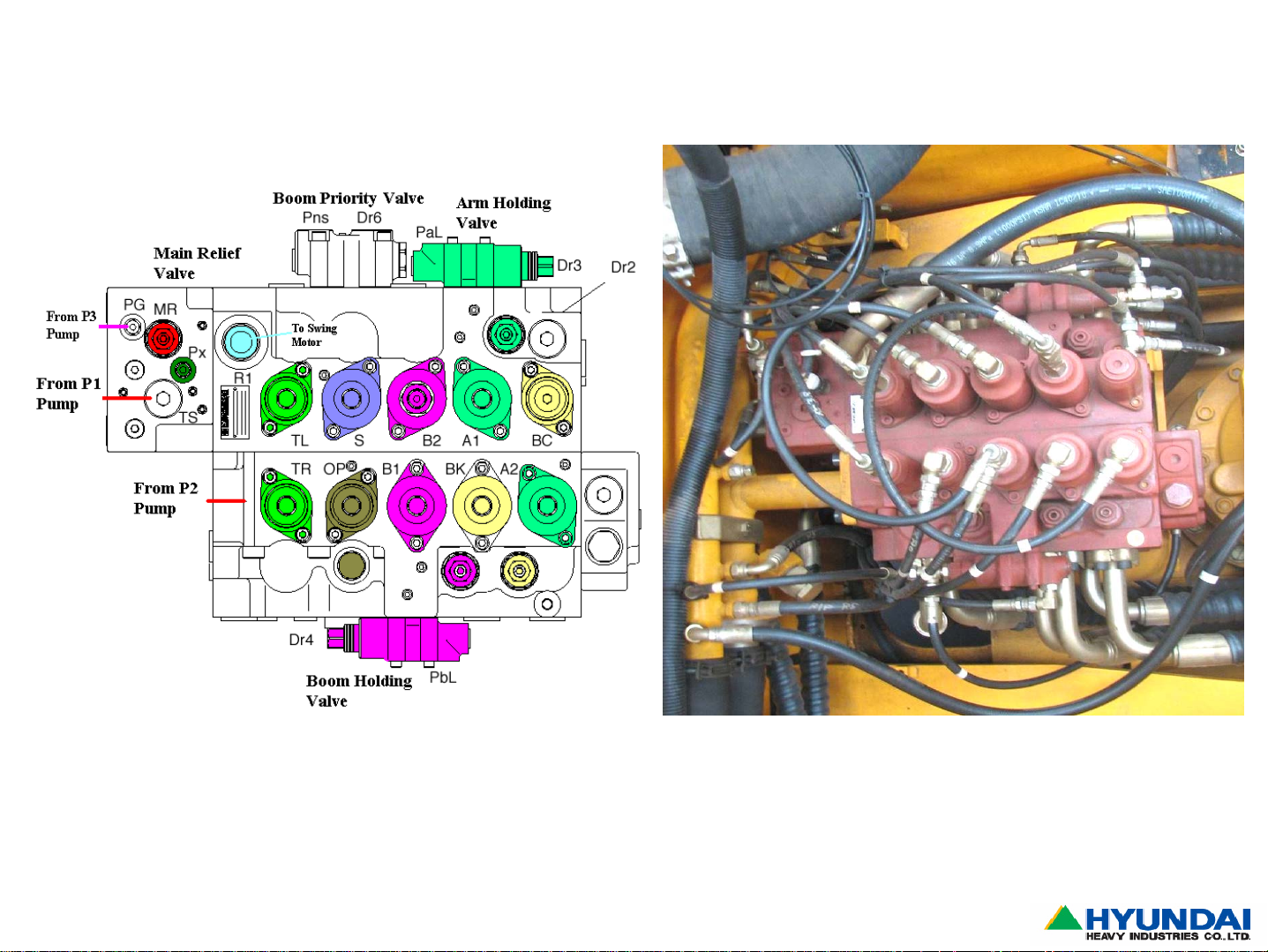
4-1A.Main Control Valve (Kawasaki)
R210LC-7
Page19
Construction Equipment
Page 21
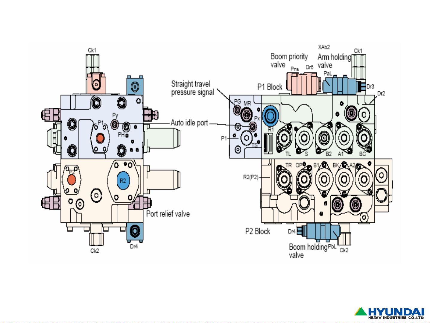
R210LC-7
Page20
Upper viewSide view
Construction Equipment
Page 22
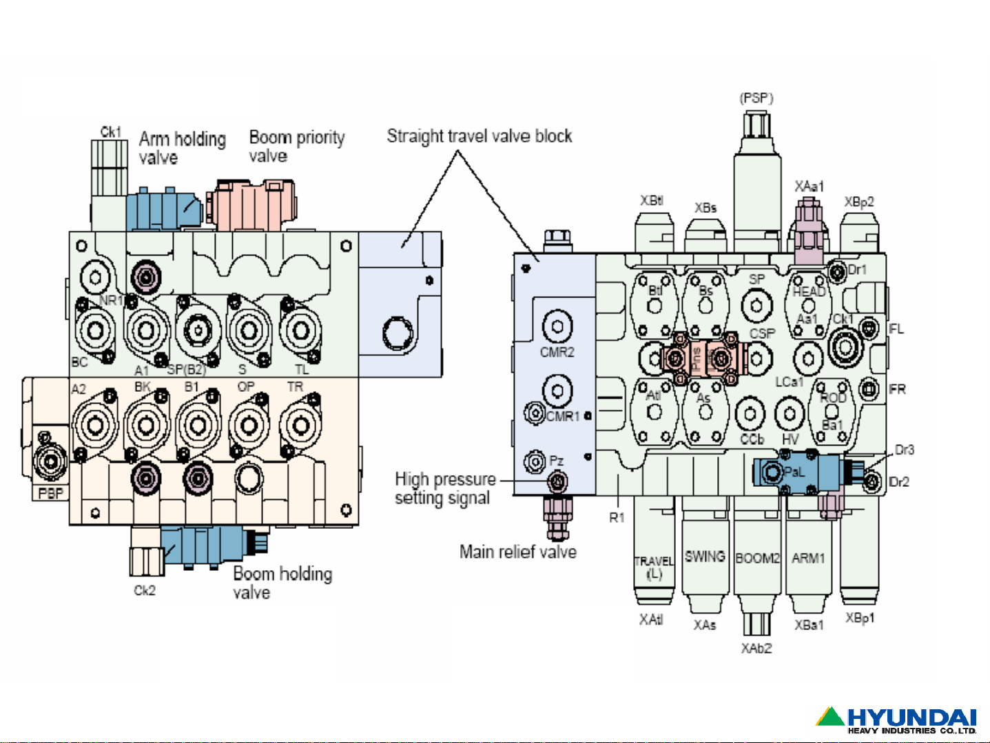
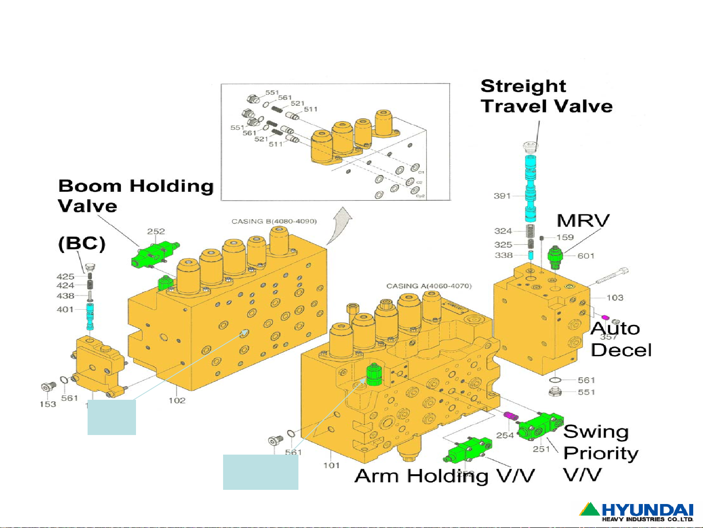
R210LC-7
Page21
Bottom view
Side view
Construction Equipment
Page 23
R210LC-7
Page22
RH
LH
Construction Equipment
Page 24
1)Foot Relief Valve
R210LC-7,R290LC-7A
Page23
Construction Equipment
Page 25
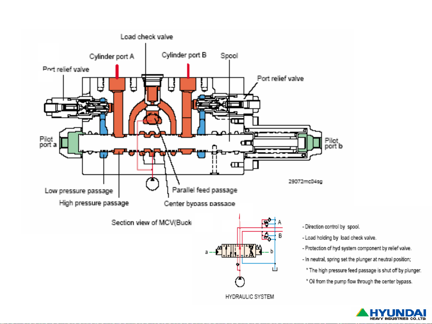
2)Direction Control Valve
R210LC-7,R290LC-7A
Page24
Construction Equipment
Page 26
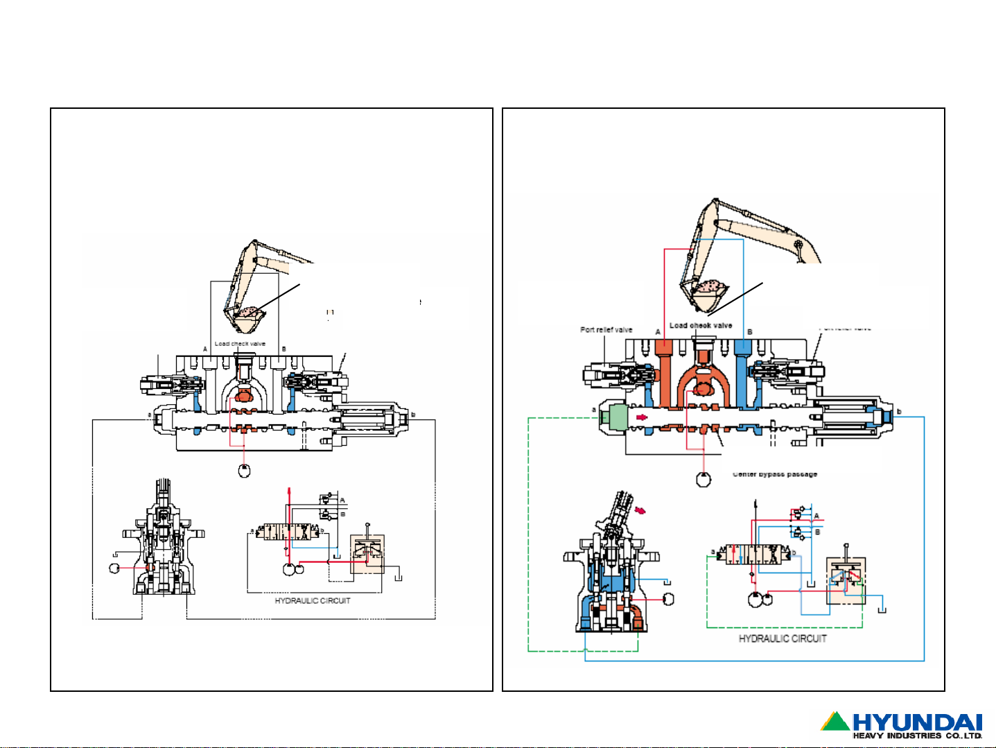
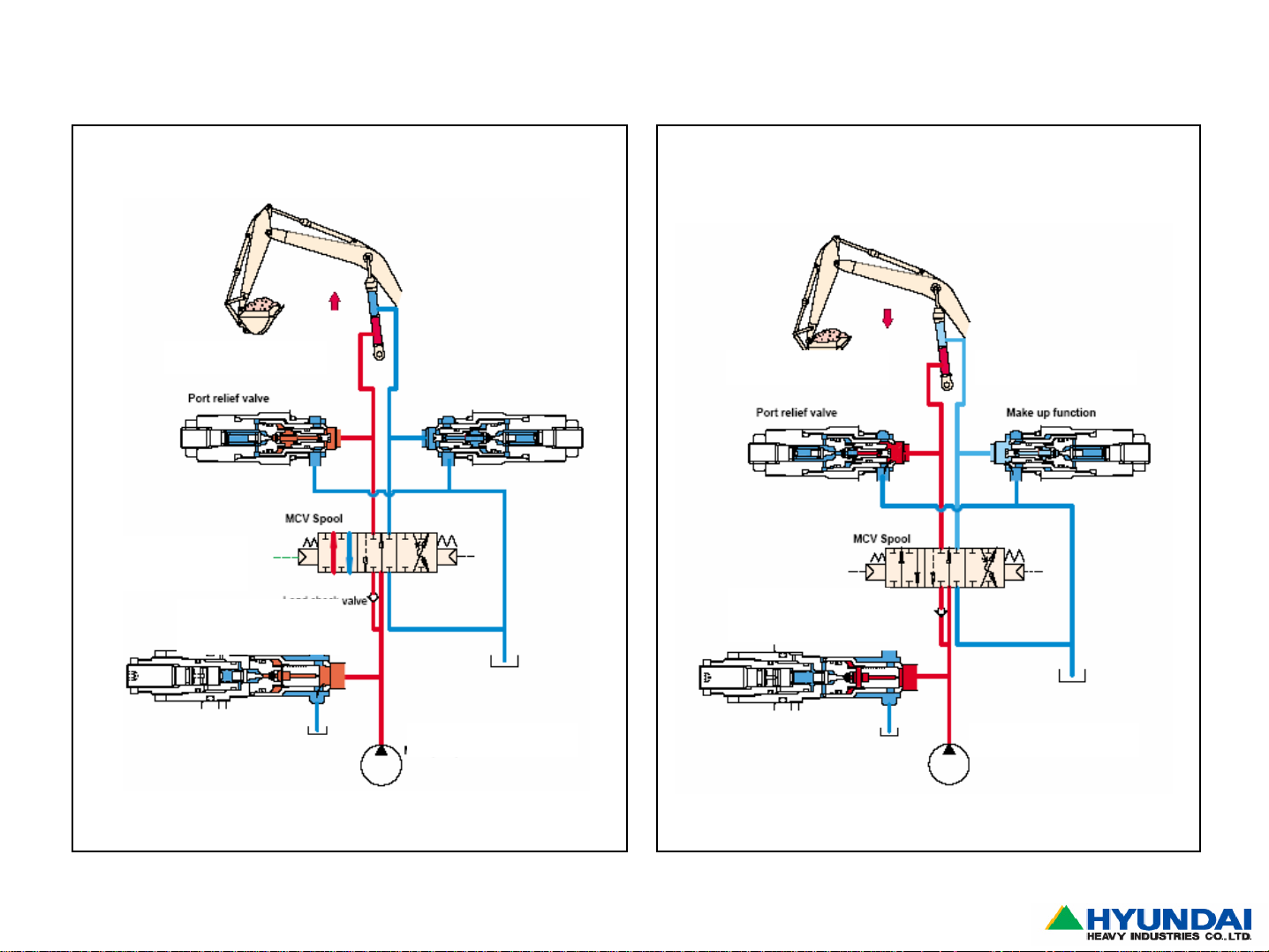
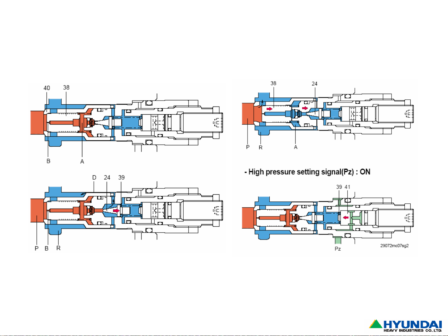
3)Port Relief Valve
R210LC-7,R290LC-7A
Neutral Position
Port Relief
valve
Load check
valve
Port Relief
valve
Operation Position
Port Relief
valve
Load check
valve
Port Relief
valve
Center Bypass valv e
Page25
Construction Equipment
Page 27
R210LC-7,R290LC-7A
Page26
Construction Equipment
Page 28
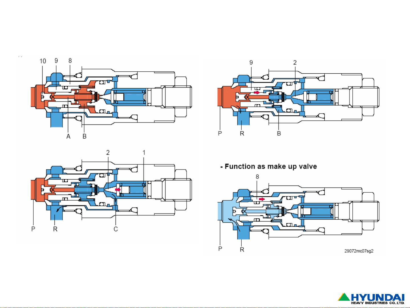
4)Main Relief Valve & Load Check Valve
R210LC-7,R290LC-7A
Port Relief valve
Load check
V/V
Main Relief
valve
Main Pump
Make Up valvePort Relief valve
Main Relief
valve
Main Pump
Page27
Construction Equipment
Page 29
R210LC-7,R290LC-7A
Page28
Construction Equipment
Page 30
5)Arm-In Operation ( Regeneration)
-Improve arm-in speed
-Prevent arm cylinder cavitation
Page29
Construction Equipment
Page 31

Page30
Construction Equipment
Page 32

Arm Roll Out
Page31
Construction Equipment
Page 33

6)Boom Priority System ( Boom & Swing Operation)
Page32
Construction Equipment
Page 34

7)Straight Travel Valve
Page33
Construction Equipment
Page 35

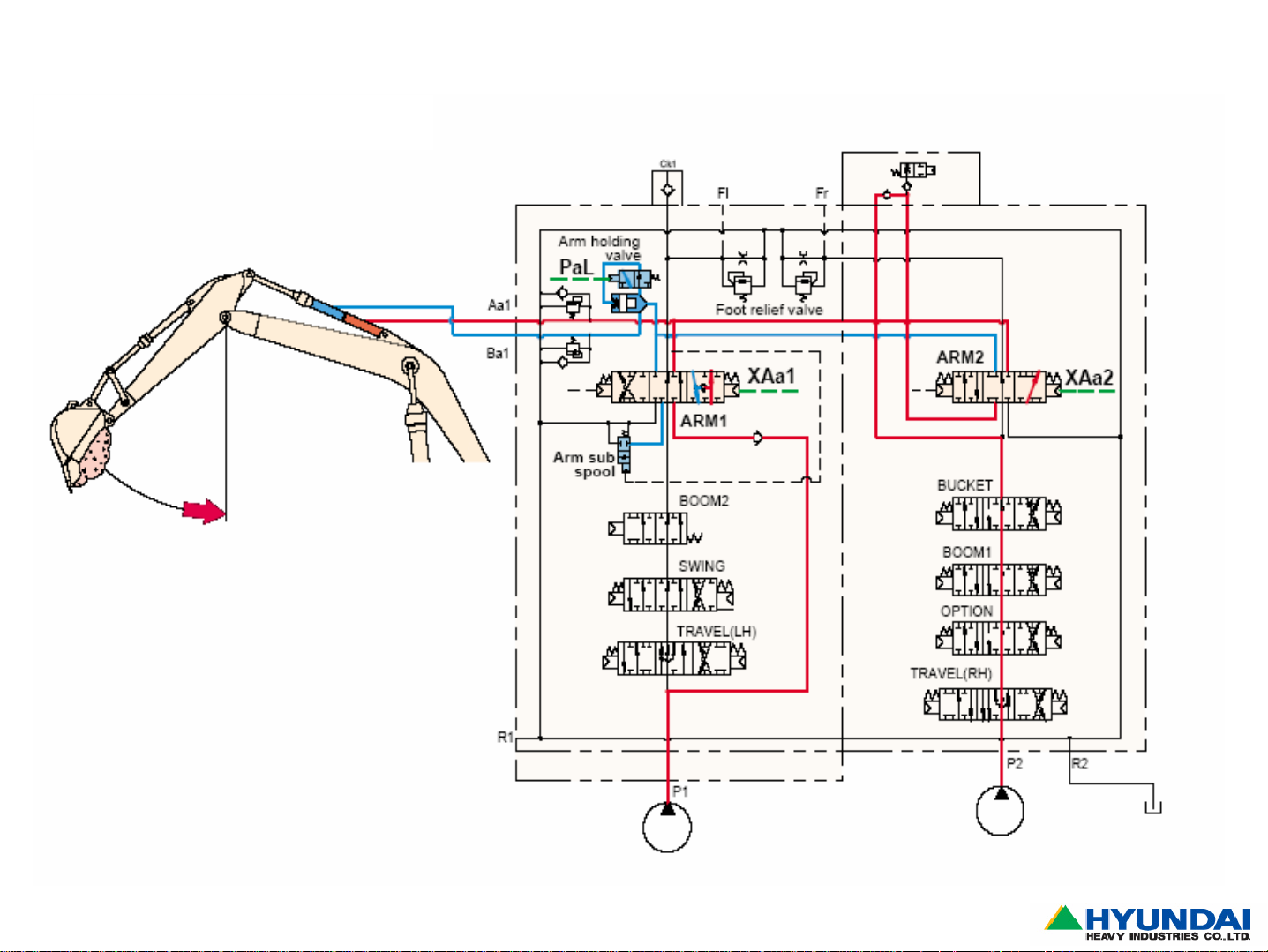
8)Boom & Arm Holding Valve
Boom
spool
R290LC-7A
Pal
Pal
Page34
Pal
Boom Holding valve open
Boom Holding valve closed
Construction Equipment
Page 36

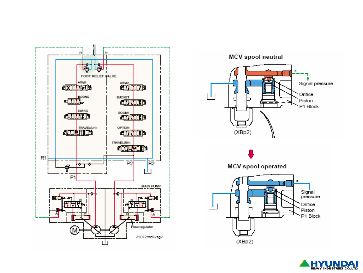
9)Auto Idling Control System
Neutral Position Operated Position
R290LC-7A
Page35
Construction Equipment
Page 37

10)Straight Travel Valve at Neutral position
R290LC-7
Page36
Construction Equipment
Page 38

11)Travel and Swing Simultaneously
R290LC-7
Page37
Construction Equipment
Page 39

4-1B. Hanil-MCV
R110/140/160/180LC-7
Signal to
open v/v
Pc41
Drain3
Option PS 37
(NO, auto decel)
NEGATIVE
RELIEF
VALVE 2
Neg Contrl Sig Pn2
Neg Contrl Sig Pn1
OPTION C
NEGATIVE
RELIEF
VALVE 1
Arm Holding
Valve (AHV)
DOZER
BUCKET
LOW
F
-
2
P
ARM1
TRAVEL
RIGHT
BOOM2
OPTION A
(1 side)
LOW
F
-
1
P
SEC.
RELIEF
V/V BUCK
DRAIN
SWING
PORT
SWING
ARM2
OPTION
PORT
Trav alarm PS
BOOM 1
SEC.
RELIEF
V/V BM
Straight Travel
Valve (TS)
TRAVEL
LEFT
Boom Holding
Valve (BHV)
Drain2
(Sw Prior &
Boom2)
Main Relief
Valve
Signal to
open v/v
Pb21
Power
Boost
Signal
Drain1
chek v/v ‘s
MR
FRONT VIEW
Regen. Command Sign
ARM
REGENERATION
SEC.
RELIEF
V/V BUCK
Pc42 (From Arm-In)
OPTION C
BUCKET
DOZER
ARM1
BACK VIEW
RETURN
P2 (ENG
SIDE
PUMP)
Regen. Cut Sign Pb4
ARM2
SWING
PRIORITY
SEC.
RELIEF
V/V ARM
BOOM1
SWING
Work PS CD7
(NO, auto decel)
PO (PILOT
OIL
ENTRANCE
)
P1 (OUTER
PUMP)
relief valve option A
location
Swing
prior sig
SEC.
RELIEF
V/V BOOM
TRAV
LEFT
TRAV
RIGHT
Drain0
Straight
Trav V/V
Page38
BOTTOM VIEW
Construction Equipment
Page 40

TRAVEL
LEFT
R110/140/160/180LC-7
Orifice
BUCKET
Lb1
DRAIN
SWING
PORT
OPTION
(1 side)
BOOM 1
ARM2
Qr
Regeneration
L01
OPTION
PORT
K1
Zm
PLUG
PLUG
K4
K3
Power
boost
K1
K4
Lb1
Lb2
EXTRA A (OPTION)
& ARM
REGENERATION
L01
Zm
K3
Page39
Lb2
Construction Equipment
Page 41

STRAIGHT
TRAVEL
TRAVEL
DOZER
RIGHT
ARM1
SWING
BOOM2
BOOM2
&
SWING
PRIORITY
DOZER
(EXTRA B)
OPTION
ARM1
SWING
OPTION
(EXTRA C)
Qr
REGENERATION)
(
PO (PILOT OIL
ENTRANCE)
PLUGS
p 2-23
p 2-25
Ks
V3 PLUG
Q2
PLUG
Q1
Q2 (SUMM)
summation
line for arm
(arm 2)
Q1
Ks
Page40
Construction Equipment
Page 42

15
R110/140/160/180LC-7
ARM
1
9
10
11
CYL
ARM1
2
BOOM2
(OPT)
TANK
STRAIGHT
TRAV V/V
12
SWING
TRAVEL LEFT
3
6
4
7
8
ARM2
BUCKET
OPTION
13
BOOM1
14
BOOM
HOLDING
VAVLE
17
TRAVEL RIGHT
Page41
16
Pilot Press
Construction Equipment
Page 43

R140W-7
⑥
⑤
④
③
②
①
⑪
⑩
⑨
⑧
⑦
⑪
⑩
⑨
⑧
⑦
⑥
⑤
④
③
②
①
Page42
Construction Equipment
Page 44

1) SPOOLS
① OPTION (Dozer for Wheel
excavator)
② BOOM1
③ ARM2
④ ARM REGENERATION
⑤ BUCKET
⑥ TRAVEL
⑦ SWING
Page43
⑧ BOOM2
⑨ ARM1
⑩ OPTION
⑪ OPTION
Construction Equipment
Page 45

2) SPOOL Location-1
Dr0
PORT Relief v/v
Negative Relief
v/v
Pb1
Pc1
Pb20 Pc2
Pb3
Pb4Pc42
Pb5 Pc5
Pn1
Pc3
Pc40
Pc6
PORT Relief v/v
Pb1 Dozer up
Pb20 Boom down
Pb3 ARM-In confluence
Pc42 ARM Regeneration
Pb4 ARM Regeneration cut
Pb5 BUCKET Out
Dr0 Drain
Pc1 TRAVEL Reverse
Pc2 RH SWING
Pc3 SWING Priority
Pc40 ARM-In
Pc5 OPTION B
Pc6 OPTION C
Page44
Construction Equipment
Page 46

3) SPOOL Location-2
Ai
Main relief v/vStraight
Travel spool
AUTO IDLE
S/W
PORT Relief v/v
Pd1
Pd6
Pa1
Pa20Pd2
Pd41Pa21
Pa4Pd40
Pa5Pd5
Pn2
Negative Relief v/v
PORT
Relief v/v
Pd1 TRAVEL Reverse
Pd2 SWING(LH)
Pa21 BOOM RAISE confluence(BOOM2)
Pd40 ARM Out
Pd5 OPTION B
Pd6 OPTION C
Pa1 DOZER Down
Pa20 BOOM Raise
Pd41 ARM Out confluence(ARM2)
Pc40 OPTION(Breaker)
Pc6 BUCKET In
Page45
Construction Equipment
Page 47

4) ATTACHMENT Supply port-1
Rs
B5 A5
B4
Dr2
Page46
B2
B1 A1
Rs SWING Make-up
B5 BUCKET Out
B4 OPTION A(BREAKER)
B2 BOOM Down
Dr2 Drain
B1 OPTION(DOZER Raise)
A2
Dr1 Pb21
A5 BUCKET In
A2 BOOM Raise
A1 OPTION(DOZER Down)
Dr1 Drain
Pb21 BOOM Holding release
Construction Equipment
Page 48

5) ATTACHMENT SUPPLY port-2
D1C1
C2
C4
C5
C6
C1 TRAVEL Reverse
C2 SWING(LH)
C4 ARM In
C5 OPTION B
C6 OPTION C
D2
V3
D4
Pc41Dr3
D5
D6
D1 TRAVEL Forward
D2 SWING(RH)
D4 ARM Out
D5 OPTION B
D6 OPTION C
Dr3 Drain
PC41 ARM Holding release
Page47
Construction Equipment
Page 49

6) NEGATIVE Control port
Plug
2-8. P1,P2 Port
Plug
Pn1
Pn2
오리피스
P2
T1
P1
Page48
Construction Equipment
Page 50

7) CHECK Valves -1
OPTION”C”
Plug
OPTION”B”
ARM 1
BOOM2
(SWING
Priority)
Q1
Q2
Ks
SWING
TRAVEL
BUCKET
ARM
Regeneration
OPTION”A”
ARM 2
BOOM 1
DOZER
Page49
Construction Equipment
Page 51

8) CHECK Valves -2
Rs SWING Make-up
B5 BUCKET Out
B4 OPTION A(BREAKER)
B2 BOOM Down
Dr2 Drain
B1 OPTION(DOZER Raise)
Plug
A5 BUCKET In
A2 BOOM Raise
A1 OPTION(DOZER Down)
Dr1 Drain
Pb21 BOOM Holding release
OPTION”C”
OPTION”B”
LB1,LB2
BUCKET
Page50
K1
Pu
CMR1,CMR2
ARM 1
Qr
BOOM2
(SWING
Priority)
K3
SWING
K4
TRAVEL
ARM
Regeneration
OPTION”A”
L01
ARM 2
ZM
BOOM 1
DOZER
Construction Equipment
Page 52

9) BUCKET Orifice
; When combined operation with BUCKET,
it allow to supply much oil to ARM/BOOM.
OPTION”C”
OPTION”B”
ARM 1
BOOM2
(SWING
Priority)
SWING
BUCKET
ARM
Regeneration
OPTION”A”
ARM 2
BOOM 1
Page51
TRAVEL
DOZER
Construction Equipment
Page 53

10) NEGATIVE Relief Valve
● RCV Neutral : Bypass pressure up-Pump flow decrease
● RCV Operation : Bypass pressure down-Pump flow increase
Drain
28 bar
()
Page52
Bypass
passage
Construction Equipment
Page 54

11) Holding valve
11-1) Composition
(Drain)
Piston “B”
Piston “A”
Sest-poppet
Poppet
Check
v/v
Spring”B”
Spring
Pb21DR3 Holding release
port
Page53
Construction Equipment
Page 55

11-2) ARM
Holding release
ARM 1 SPOOL
Page54
ARM In pilot
port(Pc40)
Holding release Pilot port
(Pc41)
Drain Port
Drain Port
Holding release
Pilot Port (Pc41)
ARM Cyl.
When ARM In operation, PILOT pressure can
act on Pc40(ARM 1 Spool),Pc41(Holding
release port) and ARM will be lower down.
Construction Equipment
Page 56

11-3) ARM Holding
The Return oil from ARM CYL.(A) is blocked by the Check valve(C) and so it can
not flow to the ARM Spool section(B).
Ⓑ
Ⓐ
Page55
Check
Ⓒ
ARM CYL.
Spring
Construction Equipment
Page 57

12) ARM Regeneration
12-1) Concept
A
B
While the ARM moves down from “A” to “B”
position as the figure, Return oil quantity will
exceed the supply oil amount cause of the
ARM gravity. It can make a Cavitation.
To make stop Cavitation, Return oil from
cylinder flow to the supply line.
Page56
(ARM Regeneration-Check v/v)
Construction Equipment
Page 58

12-2) ARM Regeneration circuit
* PILOT Supply port
when ARM In operation
① Pc40 ARM 1 Spool
①
②
ARM 1
④
ARM
Regen.
ARM 2
② Pc41 ARM Holding release
③ Pc42 Selection v/v
③
④ Pb3 ARM 2 Spool
Pc42
Page57
Construction Equipment
Page 59

12-3) ARM Regeneration - Action
Pc42
Pc42
Page58
ARM 1
ARM
Regen.
ARM 2
Construction Equipment
Page 60

13) AUTO IDLE
; One for Attachment, the other one for travel operation check.
Page59
Construction Equipment
Page 61

4-1C. Pressure Settings
UNIT: BAR
110LC-7 140LC-7 160LC-7 180LC-7 210LC-7 250LC-7 290LC-7 320LC-7 360LC-7 450LC-7
*500LC-7
MAIN CONTROL MAIN RELIEF 330 330 330 330 330 330 330 330 330 330
VALVE POWER BOOST 360 360 360 360 360 360 360 360 360 360
PORT RELIEF 380 380 380 380 390 390 390 390 390 390
(arm, boom, bucket) *380
SWING MOTOR RELIEF PRESS 240 240 240 240 240 275 265 265 260 285
(measured on swing motor)
BRAKE RELEASE 33~50 30~50 20 20 33~50 33~50 29~32 26 30 20~50
TRAVEL MOTOR RELIEF PRESS 330 330 330 330 365 365 375 330 335 345
BRAKE RELEASE < 9 6 6 6 6 6 16 16 9 17~50
PILOT PUMP RELIEF PRESS 35 35 35 35 35 35 35 35 35 33 - *35
OVERLOAD RELIEF PRESSURES FOR LONG REACH MODELS:
MODEL
R210LC/LR-7
R290LC/LR-7
Page60
ARM IN & OUT
300 bar
230 bar 270 bar
BUCKET IN & OUT
280 bar
Construction Equipment
Page 62

Subject 1 : Only one attachment speed is slow
1.Problem : attachment speed is slow
2.Check & Measure : Only one attachment speed is slow
1) Condition : S Mode, max rpm
2) Test Items and Specifications
Page61
Pressure
Measuring Point
Pilot Main
Boom
Arm
40Kg/㎠ 330Kg/㎠
40Kg/㎠ 330Kg/㎠
Travel 40Kg/㎠ 330Kg/㎠
Deviation 40Kg/㎠ 330Kg/㎠
Test result
Remedy (If not)
(Kg/㎠)
Construction Equipment
Page 63

3) Measuring point for pilot pressure
※ How to measure
(1) disconnect Pilot Hose
(2) connect the disconnect
hose to Gauge “T” fitting
(3) start the engine
※ Test Items and Specifications
Page62
Pilot Pressure
Attachment
In Neutral Full
Boom
0Kg/㎠ 40Kg/㎠Arm
Test result
Remarks (If Not)
(Kg/㎠)
See RCV
See RCV
Bucket See RCV
Construction Equipment
Page 64

4) Measuring point for main pressure
※ How to measure
1) disconnect pilot hose
2) connect the disconnect
hose to gauge “T” fitting
3) start the engine
※ Test Items and specifications
Main
relief
Main 330/360Kg/㎠ Adjust if need
Boom 330/360Kg/㎠
Arm 330/360Kg/㎠
Bucket 330/360Kg/㎠
Page63
Relief
Valve
Pressure
(Kg/㎠)
Remarks
Bucket
relief
Arm
relief
Construction Equipment
Page 65

Subject 2 : All attachment speeds are slow
1.Problem : All attachment speeds(boom,arm,bucket) are slow
2.Check & Measure :
1) Condition : H Mode, max rpm
2) Pressure check of attachment
Kgf/㎠
Page64
R/H
Travel
L/H
Travel
Swing
Bucket
out
Bucket
In
Arm
In/Out
Boom
+ L/H
Up
Travel
Swing
P1 330
fr 30/35 - -
P2 30
150 250 170 330 320 320 220
150/35 3/35 70/35 70/35 150
280 30 240 360 180 180 200
fl - - - 0/35 0/35 0/35 0/35 2
Construction Equipment
Page 66

3.Cause
1)Abnormal result of pressure check : L/H travel, bucket out, arm in, boom up
2)Check the pressure for swing and L/H relief to find if the pump 2 oil flows to pump1.
As a result, it was found that pump 2 oil flows to pump1 side of main control valve
-bucket confluence check valve broken
4.Remedy
Replaced bucket confluence check valve
Bucket confluence
check valve
Negative control signal
port
Page65
Construction Equipment
Page 67

4-2.Pump assembly
1)View of Pump assembly
Connect to
Engine
Regulator 1
M
Pi1=Neg. Control
Pm1=Flow Cut Off
Regulator 2
Pm2=Flow Cut Off
P1 P2 Pi
Pi2=Neg. Control
EPPR Pressure
Page66
EPPR Valve
P1 front
35 bar
P2 rear Pilot Pump
Construction Equipment
Page 68

2) The Type and circuit of regulator
2) The Type and circuit of regulator
①
①
X
Y
⑤
②
④
⑦
③
⑤
③
①
⑦
⑥
Section X-X
⑥
X
②
Y
⑥
⑥
Section Y-Y
** ①~⑦ Regulator Parts Name **
① : Lever 1
② : Lever 2
③ : Compensator Piston
④ : Pilot Piston
⑤ : Adjust Screw(QMC)
⑥ : Feed Back Lever
⑦ : Spool
Page67
④
②
Construction Equipment
Page 69

3)View of regulator
3)View of regulator
The Portion of Horse Power Control
The Portion of Flow Control
Page68
Construction Equipment
Page 70

4) HHI Pump--
4) HHI Pump
regulator adjustment
regulator adjustment
Model/type
R140LC-7A
K5V80DT-1LCR-9C01
R140W-7A
K5V80DTP1LHR-9C01
R160/180LC-7A
K5V80DT-1LCR-9C05
R170W-7A
K5V80DTP1LHR-9C05
R210LC-7A
K3V112DT-1LHR-9C32
Adjustment of max.
flow control
Tightening
amount of
rpm
min-1 MPa
2,000
2,000
2,100
2,100
1,900
adjusting
screw
(954)
Turn
+1/4
+1/4
+1/4
+1/4
+1/4
Flow
change
amount
L/min Turn
-3.2 +1/4 1.44
-3.2 +1/4 1.44
-3.4 +1/4 1.54
-3.4 +1/4 1.54
-5.5 +1/4 1.48
Adjustment of min.
flow control
Tightening
amount of
adjusting
screw
(953)
Turn
+1/4
+1/4
+1/4
+1/4
+1/4
Flow
change
amount
L/min
+3.2
+3.2
+3.4
+3.4
+4.4
Tightening
amount of
adjusting
screw
(628)
Adjustment of outer spring
Compensating
control starting
pressure
change
amount
+1.88
+1.88
+1.74
+1.74
+1.56
Input
torque
change
amount
Nᆞm
+32.7
+35.1
+34.7
+34.7
+39.1
A
R250LC-7A
K3V112DT-1LHR-9C52
Page69
1,900
+1/4
-5.5 +1/4 1.48
+1/4
+1.56
50.5+4.4
Construction Equipment
Page 71

Adjustment of inner spring Adjustment of flow control characteristic
Model/type
R140LC-7A
K5V80DT-1LCR-9C01
R140W-7A
K5V80DTP1LHR-9C01
R160/180LC-7A
K5V80DT-1LCR-9C05
R170W-7A
K5V80DTP1LHR-9C05
R210LC-7A
K3V112DT-1LHR-9C32
R250LC-7A
K3V112DT-1LHR-9C52
rpm
min-1
2,000
2,000
2,100
2,100
1,900
1,900
Tightening
amount of
adjusting
screw
(627)
Turn Nᆞm
+1/4
+1/4
+1/4
+1/4
+1/4
+1/4
Flow
change
amount
L/min
+9
+9
+8.9
+8.9
+11.3
+10.7
Input torque
change
amount
+40.1
+43.0
+37.0
+37.0
+45.5
+57.9
Tightening
amount of
adjusting
screw
(924)
Turn
+1/4
+1/4
+1/4
+1/4
+1/4
+1/4
Flow control
starting
pressure
change
amount
MPa L/min
+0.17
+0.17
+0.15
+0.15
+0.15
+0.13
Flow change
amount
+9.5(-9.5)
+9.5(-9.5)
+10.0(-10.0)
+10.0(-10.0)
+12.3(-12.3)
+12.3(-12.3)
Page70
Construction Equipment
Page 72

5) Structure of pump
5) Structure of pump
Servo Piston
Swash Plate
Drive Shaft
Support
Shoe
Cylinder Block
Piston
Gear Pump Ass`y
Valve Plate
Page71
Construction Equipment
Page 73

6) View & main components of pump
6) View & main components of pump
Drive Shaft
Support
Servo Piston
Shoe
Piston
Swash Plate
Cylinder Block
Valve Plate
Page72
Construction Equipment
Page 74

Page73
Construction Equipment
Page 75

7)Symbol of Pump Assembly
Actuator,Cylinders,Motors
R210LC-7,R290LC-7A
Page74
Construction Equipment
Page 76

Drain
R210LC-7
Page75
Drain
P1
Pf (EPPR)
P2
Construction Equipment
Page 77

8)Pump Regulation Schematic
R290LC-7
Page76
Construction Equipment
Page 78

9)Pump Regulating System
A. Opening of a spool in the Main Control Valve results in flow
increase of the pump, which supplies oil to the relevant spool.
This flow increase is accomplished by
pressure decrease in front of the foot relief valve.
= NEGATIVE CONTROL SYSTEM signals: F1 & F2
B. The pump power changes, according to the selected mode on
the cluster (H, S, M, U) and work condition of the machine.
Therefore the CPU sets relevant currents towards the Electric
Proportional Pressure Reducing Valve (EPPR valve), which
establishes the pump power for P1 and P2.
= POWER SHIFT SYSTEM signal: P
EPPR
C. If P1 or P2 pressure rises significantly, both pump flows will
be reduced, according to the Pressure-Flow diagram.
= TOTAL POWER CONTROL signal: P1 & P2
Page77
Construction Equipment
Page 79

Regulator consists of the negative flow control, total horse power control and power
shift control(EPPR)
Page78
Construction Equipment
Page 80

10)Regulating Circuit
FOOT RELIEF VALVE 1 FOOT RELIEF VALVE 1
F1=NEG CONTROL SIGNAL
(0..30 bar)
Remark
The Main Relief Valve (MR) limits the
general working pressure to max. 330
bar & 360 bar for POWER BOOST.
This valve is situated on the MCV and
has 2 adjust screws. When the power
boost button (left joystick, on side) is
pushed, the MR opens at 360 bar
instead of 330 bar (only 8 sec). This is
realised by an additional pilot signal at
the back of the MR. (Find more info in
290-7MCV.pdf)
MR 210LC-7
Power Boost
Signal
F2=NEG CONTROL SIGNAL
(0..30 bar)
MODE SELECTION
H, S, M, U
SPEED SENSOR
CPU
EPPR Valve
35 bar
RPM
SETTING
35
bar
Page79
Power Boost
Solenoid
PUMP POWER
SETTING
0...35 bar
Construction Equipment
Page 81

11)Flow Pressure Chart R210LC-7
The flow pressure chart of the pump depends on the active program version of the
cluster.
400
R210LC-7, default ( = version 1.X) R210LC-7, other case ( = version 2.X)
350
300
R210LC-7(standard)
118K
92K
250
2100rpm
200
2000rpm
150
Flow Rate(l/min)
100
50
0
0 50 100150200250300350
Emergency mode
206L
217L
161K
215L
S mode
177K
114L
H mode
246K
111L
202K
107L
Deliv ery Pres sure(kgf/cm2)
EPPR (bar )
H0
S13
Emergency 15
400
350
300
92K
250
200
150
Flow Rate(l/min)
100
50
0
0 50 100 150 200 250 300 350
92K
217L
217L
93K
207L
Emerg e ncy mode
R210LC-7(standard)
105K
217L
S mode
175K
110L
H mode
177K
114L
161K
215L
190K
S mode
113L
177K
114L
202K
107L
Emergency mode
H mode
246K
111L
Deliv ery Pres sure(kgf/cm2)
EPPR (bar )
H18
S22
Emergency 15
Page80
Construction Equipment
Page 82

12)Pump Regulator
Qmax control, Qmin control, Qmax Cut control
Qmax control
Qmax Cut control
Qmin control
Page81
Construction Equipment
Page 83

13)Control and Adjustment of Regulator
13)Control and Adjustment of Regulator
-Flow Control
-
Pilot Flow Adjust.
screw(③)
Max. Flow Adjust.Screw(①)
Page82
Min. Flow Adjust.Screw(②)
Q
* Max Flow Screw Adjustment(①) *
Q
Screw Loosen (Flow ↑)
Screw Tighten (Flow ↓)
* Min Flow Screw Adjustment(②) *
Screw Tighten (Flow ↑)
Screw Loosen (Flow ↓)
Pilot P
※Gradient is not changed
* Flow Cut Off Adjustment Screw(④) *
Screw Tighten(Flow ↑)
Screw Loosen(Flow ↓)
Flow Cut Off Adjust. Screw(④)
* Pilot Flow Adjust. Screw(③) *
Screw Tighten(Flow ↑)
Screw Loosen(Flow ↓)
Pilot P
Construction Equipment
Page 84

14) Control & adjustment of regulator
14) Control & adjustment of regulator
- Horsepower Control
-
First Horse Power Adjust.
Screw(⑤)
Second Horse Power Adjust.
Screw(⑥)
Second Horse Power Adjust.
Screw(⑥)
First Horse Power Adjust.
Screw(⑤)
Page83
Q
※Gradient is not changed
* First Horse Power Adjust.Screw(⑤)
Screw Tighten (Flow ↑)
Screw Loosen(Flow ↓)
* Second Horse Power Adjust. Screw(⑥) *
Screw Tighten (Flow ↑)
Screw Loosen (Flow ↓)
Pd
Construction Equipment
Page 85

Minimum flow Maximum flow
REGULATOR
REGULATOR
max
Page84
Construction Equipment
Page 86

15)Maximum flow
-When a machine is operating, oil is supplied to the actuator(cylinder or
motors) so that no oil pressure reaches piston A.
-Then, the piston B goes back to the neutral position by the spring and the
oil in the large chamber of the piston C is returned to the tank
-Now the oil is supplied to LH side of the cylinder C.
-That pressure moves the piston C to RH side, therefore the swash plate
is positioned at maximum flow angle during operation
Page85
Construction Equipment
Page 87

16)Over Load Preventing Function (Minimazing)
-When a machine is under load or the cylinder arrives at
the end of stroke, the pressure is increased
Cylinder pressure > spring pressure (B + D)
The pressure is applied at the piston D and compresses
the spring D and B
So, the valve B moves to LH side and the oil enters the
piston C through the passage at piston B
The piston C moves the swash plate to reduce the angle
upon the angle upon the load of cylinder.
Page86
Construction Equipment
Page 88

17)Flow Control
Minimum
flow
-When the engine is running, the swash plate moves to minimum angle
position as per the following steps
1.the pressure is created by restriction of the foot relief valve
2.the pressure apply to the piston A
3.the piston A is moved to LH side
4.the valve B is opened
5.the pressure flows to the piston C
6.the piston C is moved to LH side. Therefore the swash plate is
positioned at minimum flow angle
Page87
Construction Equipment
Page 89

18)Flow Reset Function (Maximazing)
-When the load at the cylinder is gone, the pressure
in
the cylinder and in the position D is decreased
Cylinder pressure < spring force (B+D)
Then, the oil in the cylinder C returns to the tank as
shown in figure, and the swash plate angle is
increased
to give maximum flow
Page88
Construction Equipment
Page 90

19)Regulator: “Flow” Control System
When operating the excavator equipment, the negative control pressure Fi inside
regulator 1 or 2, drops, which results in displacement of the pilot piston and
increasement of the pump flow.
PRESSURE
Pm=FLOW CUT OFF
PRESSURE
Fi=NEG CONTROL
PILOT PISTON
NEG CONTROL
ADJUST SCREW
PILOT SPRING
STOPPER
PISTON
FLOW CUT-OFF
ADJUST SCREW
FLOW CUT- OFF WORKING (BREAKER mode) :
When selecting BREAKER mode on the cluster, the CPU brings in the MAX FLOW
solenoid, which supplies pilot pressure towards both regulators (= Pm signal). As a
result, the max. flows will be cut off.
Pm
Fi
FLOW
MAX
NEG CONTROL PRESSURE fi
Page89
Construction Equipment
Page 91

Flow Control Signals
35 bar
MAX FLOW CUT-OFF
SIGNAL for P1
(35 bar ON / 0 bar OFF)
MAX FLOW CUT-OFF
SIGNAL for P2
(35 bar ON / 0 bar OFF)
NEG CONTROL
SIGNAL FOR
P1(0…40bar)
Page90
REAR PUMP
(P1)
On –7 models: Max flow cut off Sig is “ON” after selecting BREAKER OPERATION
MODE
On R210/250LC-3: Max flow cut off Sig automatically “ON” in L mode
FRONT PUMP
(P2)
NEG CONTROL
SIGNAL FOR
P2 (0…40bar)
Construction Equipment
Page 92

20)Regulator: “Power” Control System
By changing the mode (H,S,M,U) the CPU varies the current towards the EPPR valve (Electric Proportional Pressure
Reducing Valve). This results in varying EPPR pressures, which work (together with P1 & P2 pressure) on the power
piston inside each regulator. The power piston & pilot piston are situated near each other and control the swash plate
angle.
In case of significant drop of engine speed, the CPU will automatically increase the current, in order to lower the pump
power and it will do this until the engine speed reaches the set-value again
REGULATOR 2REGULATOR 1
EPPR PRESSURE
0…35 bar
PEPPR
P2
P1
=
PEPPR
P1
P2
SERVO PRESSURE
35 bar
24V
fuse
(or CPU pinEPPR+)
CURRENT
0…700 mA
CPUpin EPPR-
OUPUT
Power Piston
(Compensating
Piston)
REGULATOR 1
EPPR Valve = Pf (Power Shift ) Valve
REGULATOR 2
INPUT
TABLE EPPR CURRENTS & PRESSURES
Page91
In case of faulty CPU: put machine in emergency
Construction Equipment
Page 93

-When one of the power modes is selected during operation,
the EPPR valve pressure is applied at the piston D
The piston D compresses the spring and move the valve B to
LH side
Therefore, the pump oil enters to the piston C and reduces
the
angle of swash plate
So, oil delivery of the pump is reduced.
Page92
Construction Equipment
Page 94

Page93
Construction Equipment
Page 95

21)Flow Increasing Function
R210LC-7
Page94
Construction Equipment
Page 96

22)Flow Reducing Function
R210LC-7
Page95
Construction Equipment
Page 97

23)Overload Prevention Function
R210LC-7
Page96
Construction Equipment
Page 98

24)Flow Reset Function
R210LC-7
Page97
Construction Equipment
Page 99

25)Regulator
1.Negative flow control
1.Negative flow control
2.Total horsepower control
2.Total horsepower control
3.Adjustment of input horsepower
3.Adjustment of input horsepower
①Adjustment of outer spring
②Adjustment of inner spring
Page98
4.Power shift control
4.Power shift control
5.Qmax cut control
5.Qmax cut control
6.Adjustment of maximum and minimum flows
6.Adjustment of maximum and minimum flows
Construction Equipment
Page 100

Subject 1 : Attachment operating speed for R290LC-7A is slow
1.Problem : All attachment speed is slow
2.Check & Measure
1)Test condition : S Mode, max rpm
2) Test Items and Specifications
Page99
Test
Measuring Point Condition
Spec’ Remedy (If not)
Result
Unload 1750rpm
EPPR Valve
Full 1700rpm
Unload 1850rpm
Engine RPM
Full 1800rpm
Main Relief V/V 330Kg/㎠
Pilot pressure 40Kg/㎠ Adjust pilot relief V/V
Fr & Fl pressure
In neutral 38Kg/㎠
In full 5Kg/㎠
Construction Equipment
 Loading...