

Hyundai CIT-3500 User Manual
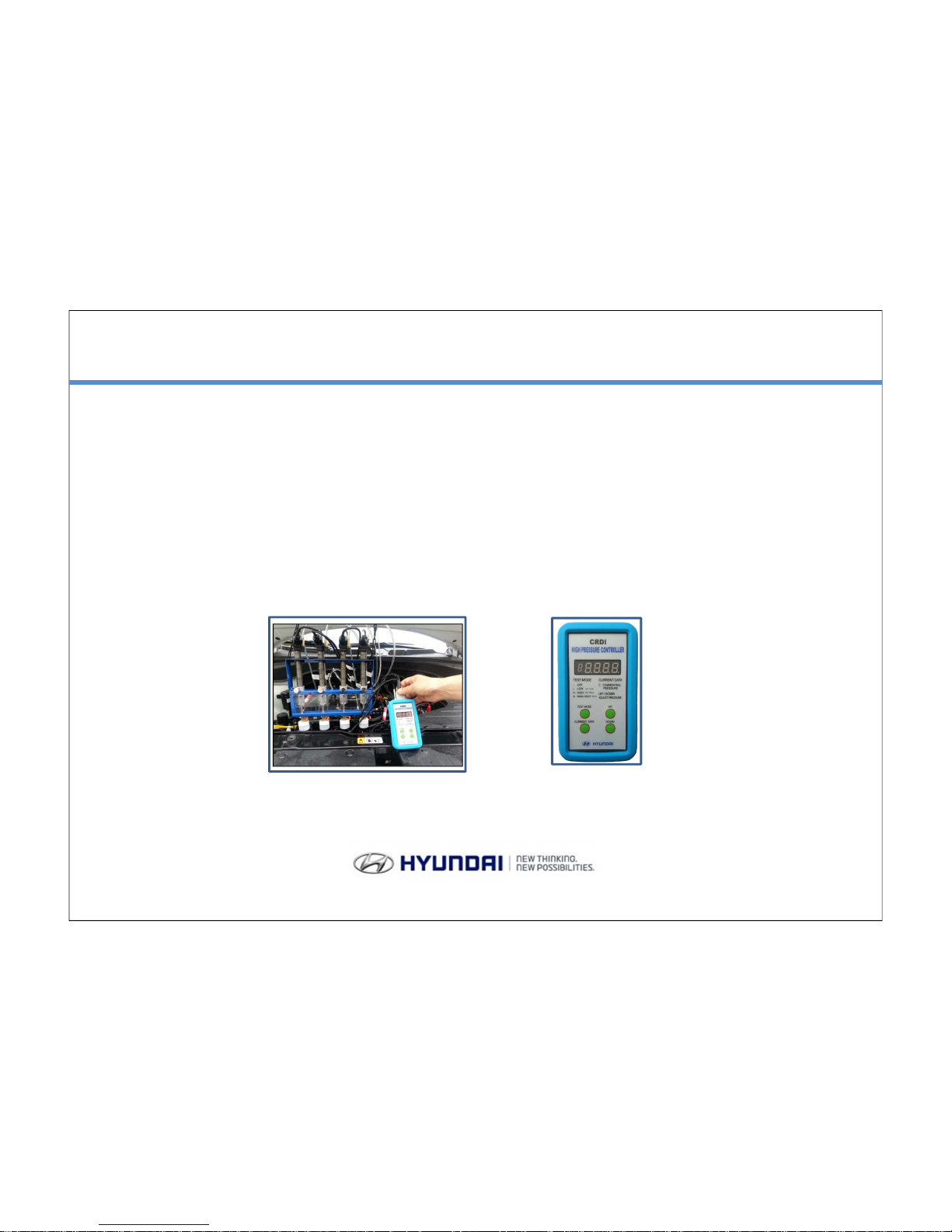
HYUNDAI CIT-3500
Common Rail Injector Tester
User’s Manual
A, U, D, J, S, R Engine & U-II, A-II
Digital Controller

Contents
1. PRODUCT COMPOSITION
2. INJECTION TEST
1) Injection Comparison Test ( Low Pressure Mode )
2) Injection Comparison Test ( Low & High Pressure Mode )
3) Test & Diagnostic
4) How to use digital CRDI HP controller
3. HIGH PRESSURE & BACK LEAK TEST
1) High Pressure Test for each system
2) High Pressure Test for each system
3) Cleaning procedure of injector
4) Injector Back Leak Test (Dynamic)
4. DIAGNOSTIC / REPAIR / INJECTOR CLEAN & ASSEMBLY & TIPS
1) Diagnostic & Repair procedure of CRDi system
2) Cleaning procedure of injector
3) Injector assembly (Nozzle area)
4) Injector assembly (Nozzle area)
5) Tips for Injector assembly (Nozzle area)
5. TECHNICAL INFORMAITON
6. PIEZO INJECTOR
1) PIEZO Injector test
2) Measurement Test of injected-fuel-quantity
3) PIEZO Injector Low Fuel Test
1
This new Injector Tester has developed in order to improve diagnostic efficiency and
accuracy for Common Rail System in the vehicle.
Enables Injection Amount Comparison Test under Low and High fuel pressure conditions
that was not possible with GDS/G-Scan .
Also Cylinder compression and Rail pressure regulator test are additionally available.
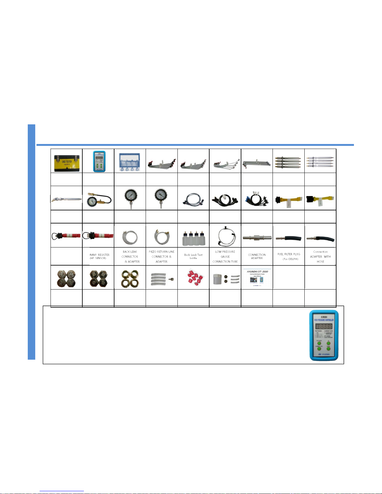
1. CIT-3500 Composition
Tool Case
CRDI HIGH
PRESSURE
CONTROLLER
INJECTOR MESS
CYLINDER
TYPE-A
PIPE(M12*M12)
TYPE-B PIPE
(M12*M14)
TYPE-C PIPE
(M14*M14)
TYPE-D PIPE
(M14*M14)
BOSCH/DELPHI
DUMMY INJECTOR
NEW DELPHI
DUMMY INJECTOR
“L” DUMMY
INJECTOR &
ADAPTER
Engine
Compression Gauge
LOW PRESSURE
GAUGE
VACUUM GAUGE
BOSCH
CONNECTOR
PIEZO CONNECTOR
NEW DELPHI
CONNECTOR
RPS BOSCH
DUMMY
CONNECTOR
RPS NEW DELPHI
DUMMY
CONNECTOR
DUMMY
REGISTER(PRV)
DUMMY REGISTER
(HP SENSOR)
BACK LEAK
CONNECTOR
& ADAPTER
PIEZO RETURN LINE
CONNECTOR &
ADAPTER
Back Leak Test
bottle
LOW PRESSURE
GAUGE
CONNECTION TUBE
CONNECTION
ADAPTER
FUEL FILTER PLUG
(For DELPHI)
Connection
ADAPTER WITH
HOSE
COMMONRAIL
PLUG (FOR BOSCH
/ M12)
COMMONRAIL
PLUG
(FOR DELPHI / M14)
DUMMY INJECTOR
ADAPTER
Injector Return Line
Block Hose
Dust Cap SPARE PART Kit User’s Manual
1.
7.6.
5.4.
3.
2.
10.
9.8.
13.12.11. 14. 15.
18.
17.16.
21.20.19.
24.23.
22.
27.
26.
25.
28.
29.
30.
31. 32.
33.
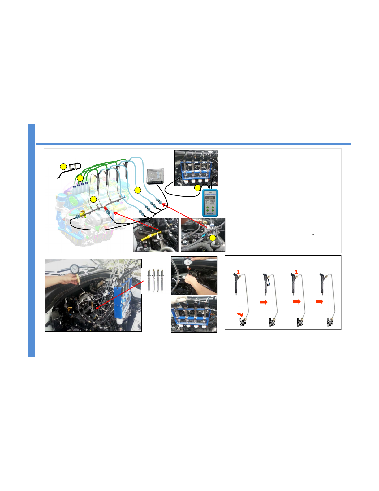
1) LOW PRESSURE MODE TEST
LOW PRESSURE MODE TEST
1. Remove the injectors from the engine
2. ① Block the return line of injectors
3. ② Install the test pipes in the rail (4ea)
and Install Test Body in injectors.
4. Install the Back Leak ③ bottle in the Injectors
5. ④ Connect the injector control wire and
holding the housing with o-ring.⑤
6. Crank the engine until the injection amount up
to the target level.⑥
NOTE :
Rail pressure will be maintained 250~350bar
automatically by vehicle’s ECU. Thus, you don’t
need to use HP controller during the test.
2-1 INJECTION COMPARISON TEST ( LOW PRESSURE MODE )
ECU
※ All the pipes must be cleaned
before installed .
( Clean it with an Air gun )
Tighten
Loosen
Flushing
IG on or Cranking
Tighten
Flushing : Crank the engine and find
the fuel leaks from the fitting area
for flushing purpose.
Remove injectors and install the dummy injectors
on the Injector hole. Block the fuel return line of
injectors to prevent fuel leaking.
2
Install Test Body
1
2
3
4
5
6
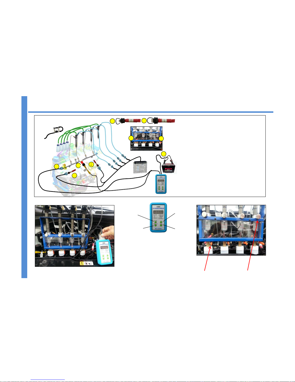
1) LOW & HIGH PRESSURE MODE TEST
ECU
2-2 INJECTION COMPARISON TEST (LOW & HIGH PRESSURE MODE )
Drain Valve
1
2
3
4
2
TEST PROCEDURE
1) Select MAX HIGH mode and crank engine for 2-3seconds.
2) Crank engine and adjust the rail pressure in Low and High
mode while engine cranking.
- LOW = 250 ~ 350 bar
- HIGH = 800 ~ 1000 bar
※ Select injection pressure using the up & down button
3) Drain the fuel from the test body.
4) Perform test for each mode: LOW & HIGH.
LOW PRESSURE MODE TEST
1) Disconnect the PRV’s & rail pressure sensor’s
connector from the rail
2) Install ① Dummy Resister and ② Rail Pressure
Sensor Dummy in each wiring connectors.
3) Connect HP controller’s wire to the ③PRV & ④ rail
pressure sensor.
5) Connect HP controller’s ⑤ power cable to battery.
4) Crank the engine until the injection amount level
of 1 or 2 test body are close to target level.
(5 scale in LOW, 8 scale in HIGH)
NOTE :
- Rail pressure can be adjusted from 100 to 1000bar by
pressure adjust knob.
- In the old model, you must use rail pressure
sensor dummy, otherwise injector will not work while
cranking.
NOTE: Battery must be fully charged before test
5
3
UP(Hold)
Test Mode
DOWN
Current data
1
1
2
Injectors Holding screw
NOTE : Perform the test more than 2 ~ 4 times to get accurate data.

LOW PRESSURE MODE JUDGMENT
HIGH PRESSURE MODE JUDGEMENT
Target
8 scale
5
6
10
11
4
3
Test & Judgment
Crank the engine until the highest level of one or more test tubes are close
to targeted level. (① LOW : 5
th
/ ② HIGH : 8thscale )
Judgment will automatically be made once you fill out measured values CRDI
diagnosis check sheet in GDS (Global Diagnosis System)
2-3 Test & Diagnostic
Select the correct groove according to engine type when
you install dummy injectors.
Quick coupling on dummy injector will help you to perform
cylinder compression test easily and quickly.
Judgments
- Please note that the engine compression standard is
showed on the shop manual.
Compression Test
Crank the engine until the injection amount of 2ndlargest fuel amount
injector is close to target level. (5 scale when low pressure mode, 8
scale when high pressure mode)
Measure the other injector’s injection amount and judge as below.
LOW PRESSURE MODE : 0.15 ㎖ ( 1.5 scale ) or higher is normal
HIGH PRESSURE MODE : 0.5 ㎖ ( 5 scale) or higher is normal
For user who has no GDS
4
Adapter for
New (A-ENG) Injectors
2
1
LOW PRESSURE GAUGE
Engine Compression Gauge
 Loading...