

Page 1

RD625
Digital Wall Mounted Repeater
OWNERS MANUAL
Page 2

Page 3

Preface
Thanks for your favor in our product. To derive optimum performance from the product, please read this manual and the
Safety Information Booklet carefully before use.
This manual is applicable to the following product:
RD62X Digital Wall-mounted Repeater(X may represent 2, 5, 6 or 8)
Page 4
Instructional Icons
Caut ion: Indicat es situatio ns that coul d caus e
damage to your product or bodily injury.
No te: Indica tes ti ps tha t ca n he lp you mak e
better use of your product.
Term Explanation
Voltage Standing Wave Ratio (VSWR)
Voltage Standin g Wave Ratio (VSWR) is a value that
measures how well a load is impedance-matched to a
source.
Copyright Information
Hyt er a is the trade mar k or regi ste re d tra de mar k of
Hyt era Comm uni catio ns Co., L td. (the Com pan y) in
PRC and/or other countri es or ar eas. The Comp any
reta ins the owne rshi p of its t rade mark s and produc t
nam es. Al l oth er trad ema rks and/o r pr odu ct name s
that may be used in this manual are properties of their
respective owners.
The product described in this manual may include the
C
ompany’s computer programs stored in memory or
othe r medi a. Laws in PRC and/or other countries or
areas protect the exclusive rights of the Company with
respect to its computer programs. The purchase of this
product shall not be deemed to grant, either directly or
by implicati on, any ri ghts to t he purchaser regarding
th e C o mp a ny’s com put e r p ro g ra ms. An y of the
Compan y’s computer programs may not b
modified, distributed, decompiled, or reverse-engineered
in any manner without the prior written consent of the
Company.
The AMBE+2
this product is protected by intellectual property rights
including patent rights, copyrights and trade secrets of
Digital Voice Systems, Inc. This voice coding technology
is licensed solely for use within this product. T
this technology is explicitly prohibited from attempting to
decompile, reverse engineer, or disassemble the Object
Code or in any other way convert the Object Code into a
human-readable format.
TM
voice coding technology embodied in
e copied,
he user of
U.S. P a t e n t No : #6 ,912, 49 5 B2, #6, 199 ,037 B1,
#5, 87 0, 405 , #5, 82 6,222 , #5, 75 4,9 74 , #5, 70 1,3 90 ,
#5,71 5, 365 , #5 ,64 9, 05 0, #5 ,63 0,011, #5,5 81 ,6 56,
#5,517,511, #5,491,772, #5,247,579, #5,226,084 an d
#5,195,166.
Disclaimer
Th e Co mp an y en de av or s to achieve the accu ra cy
and completeness of this manual, but no warr anty of
accu racy or reliability is give n. All the speci fica tion s
and designs are subject to change without notice due
to cont in uo us tech nolo gy deve lo pm en t. No part of
this manu al may be copied, modified, tran slat ed, or
distribu ted in any manner without the expres s written
permission of us.
We do not
guaran tee, for any p articul ar purpo se, the
accuracy, validity, timeliness, legitimacy or completeness
of the Third Party products and contents involved in this
manual.
If you have any suggestions or would like to learn more
details, please visit our website at: htt p://www.hytera.
com.
RF Radiation Information
Thi s pro duc t mu st be r est ric ted to ope rat ion s in an
Occupatio nal/Control led RF exposu re Env ironm ents.
Us ers mu st be fu lly aw ar e o f t he ha zar ds of th e
expo sure and abl e to exercise cont rol over their RF
exposure to qualify for the higher exposure limits.
RF Radiation Profile
Radio Frequency (RF) is a frequency of electromagnetic
ra dia ti on in th e ran ge at whic h rad io si gn als are
t r a nsm it te d. RF te c h n o l o g y is wi de ly u s e d in
commun icatio n, medici ne, food processing and other
fields. It may generate radiation during use.
RF Radiation Safety
In order to ensure user healt h, expert s from relevant
industries including science, engineering, medicine and
health work with international organizations to develop
sta ndar ds for saf e exp osure to RF r adi ati on. The se
standards consist of:
●
United States Federal Communications Commission,
Code of Federal Regulations; 47CFR part 2 sub-part
J;
●
Am er ica n Na ti ona l St and ar ds Inst it u
Institute of Electrical and Electronic Engineers (IEEE)
C95. 1-1992;
●
Institute of Electrical and Electronic Engineers (IEEE)
C95.1-1999;
●
International Commission on Non-Ionizing Radiation
Protection (ICNIRP) 1998.
te (ANS I)/
FCC Regulations
Federal Communic atio n Commissio n (FCC) require s
that all radio communication products should meet the
require ments set f orth in the above standards before
they can be marketed in the U.S, and the manufacturer
shall post a RF label on t he pro duct to i nform users
of oper at io na l in st ru cti ons, so as to enhanc e th ei r
occupational health against exposure to RF energy.
EU Regulatory Conformance
As certified by the qualified laboratory, the product is in
compliance with the essentia l requirements and other
relevant provisions of the Directive 1999/5/EC. Please
not e tha t the abov e inf ormation is appli cab le to E U
countries only.
7
Page 5
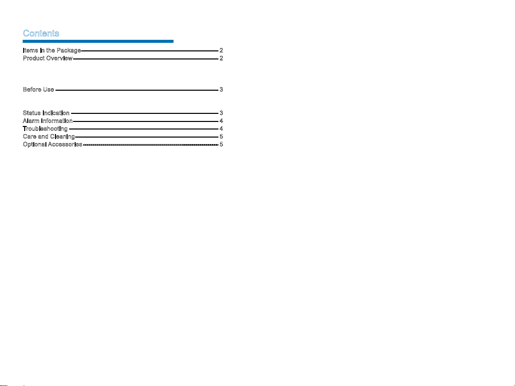
Contents
Items in the Packag e -------------------------------------------------------------------- 2
Produc t Overv iew ------------------------------------------------------------------------2
Parts------------------------------------------------------------------------------------ 2
Front Pane l --------------------------------------------------------------------------- 2
Rear Pane l --------------------------------------------------------------------------- 2
Before U se --------------------------------------------------------------------------------- 3
Instruction s --------------------------------------------------------------------------- 3
Wall-mount Bra cket Insta llatio n (Optional) --------------------------------- 3
Status I ndicat ion ------------------------------------------------------------------------- 3
Alarm I nforma tion ------------------------------------------------------------------------4
Troubleshooting -------------------------------------------------------------------------- 4
Care and C leaning ----------------------------------------------------------------------- 5
Optional Acce ssori es ------------------------------------------------------------------- 5
1
Page 6
Items in the Package
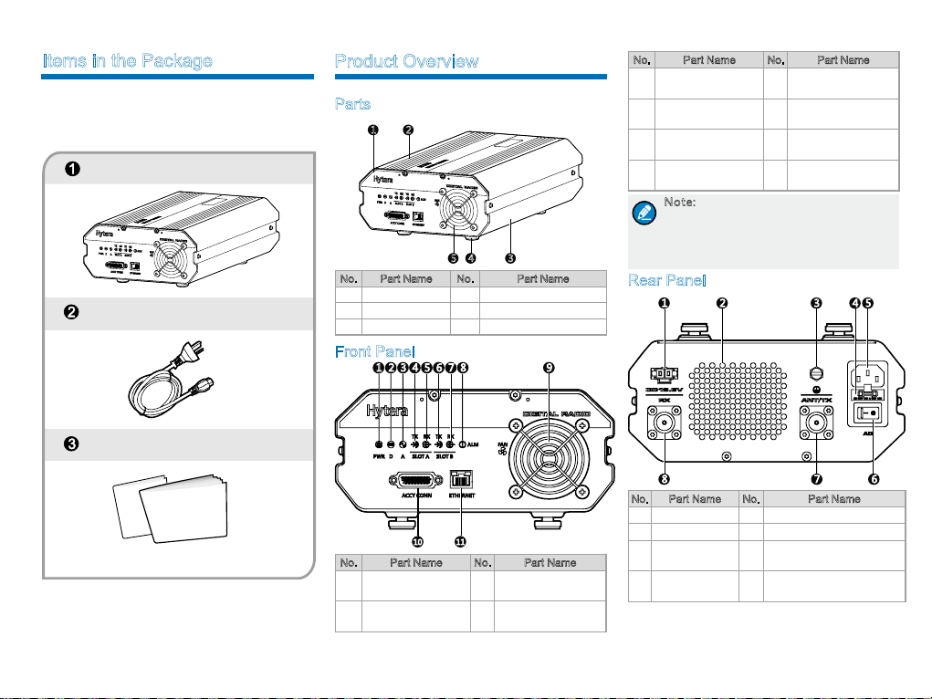
Please unpack carefully and check that all items listed
below are received. If any item is missing or damaged,
please contact your dealer.
Repeater
AC Power Cord
Documentation Kit
Product Overview
Parts
1
2
345
No. Part Name No. Part Name
1 Front Panel 4 Foot Pad
2 Upper Cover 5 Fan Mesh Enclosure
3 Chassis / /
Front Panel
124 5
3
6 7 8
9
No. Part Name No. Part Name
Analog Mode LED
3
Indicator
Slot A TX LED
4
Indicator
Slot A RX LED
5
Indicator
Slot B TX LED
6
Indicator
Note: If the repeater is manufactured
without internal duplexer, then part 8 will
be an external duplexer RX por t; if it is
manufactured with internal duplexer, then
there will be no connection inside part 8.
9 Fan Inlet
10 Accessory Connector
11 Ethernet Interface
/ /
Rear Panel
1
2 3
4 5
78
Safety
Owner's Manual
10 11
No. Part Name No. Part Name
1 Power LED Indicator 7
Digital Mode LED
2
Indicator
Slot B RX LED
Indicator
8 Alarm LED Indicator
No. Part Name No. Part Name
1 DC Power Inlet 5 AC Power Inlet
2 Fan Outlet 6 AC Power Switch
3 Ground Terminal 7
4 Fuse Box 8
ANT/TX Antenna Connector
(N-type Female)
R X An ten na C o nn ec to r
(N-type Female)
6
2
Page 7
Before Use
Instructions
To ensure optimum performan ce and reliability of the
repeater, please read the following instructions carefully.
Operation Environment
Th e repea te r mus t be ins tal le d in a dr y and wel lventilated place with amb ient temperature of -30℃ to
+60℃ and relative humidity of not more than 95%.
Voltage Check
Check whether the input voltage is within the operating
voltage of the repeater (DC power supply: 13.6V±15%;
AC power supply: 90V to 264V).
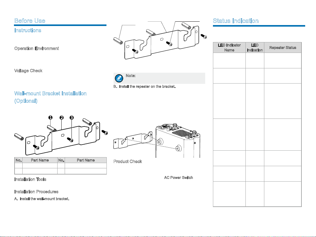
Wall-mount Bracket Installation
(Optional)
If you need to install the repeater on the wall, please
contact your dealer to purchase a wall-mount bracket.
No. Part Name No. Part Name
1 Plastic Wall Anchor 3 Self-tapping Screw
2 Wall-mount Bracket / /
Installation Tools
An electric drill and a T10 torx screwdriver.
Installation Procedures
A. Install the wall-mount bracket.
1. Drill three holes into the wall, with each hole aligned
with those of the wall-mount bracket.
2. Put the plastic wall anchor into the drilled holes. Skip
this step if the wall is not a concrete wall.
3
1
2 3
Self-
Plastic Wall
Anchor
3. Use three ST4X16 self-tapping screws to fasten the
bracket on the wall.
Note: Make sure the wall can support the
repeater’s weight before drilling.
B. Install the repeater on the bracket.
1. Align the screws on the upper side of the repeater
wi th the no tc he s of th e br ac ket and mou nt the
repeater onto the bracke t, as sho wn in the figur e
below;
2. Move the repeater side to side slightly to ensure the
screws fit into the bottom of the notch.
Wall-mount
Bracket
tapping Screw
Product Check
Check whether the repeater works properly by observing
the seven LED indicato rs in the f ront panel after the
repeater is powered on via the
AC Power Switch.
Status Indication
The LED indi ca to rs on t he fron t panel ind icate the
following repeating status:
LED Indicator
Name
Digital Mode LED
Indicator
Analog Mode LED
Indicator
Slot A TX LED
Indicator
Slot A RX LED
Indicator
Slot B TX LED
Indicator
Slot B RX LED
Indicator
Alarm LED
Indicator
LED
Indication
Blue
Yellow
Red
Green
Red
Green
Red
Repeater Status
The repeater is
operating in digital
mode.
The repeater is
operating in analog
mode.
●
Analog mode:
The repeater is
transmitting.
●
Digital mode:
The repeater is
transmitting in Slot
A.
●
Analog mode:
The repeater is
receiving.
●
Digital mode:
The repeater is
receiving
Digital mode:
The repeater is
transmitting in Slot B.
Digital Mode: The
repeater is receiving
in Slot B.
Alarm occurs. The
alarm LED indicator
will remain red
until all alarms are
eliminated.
in Slot A.
Page 8
Alarm Information
Troubleshooting
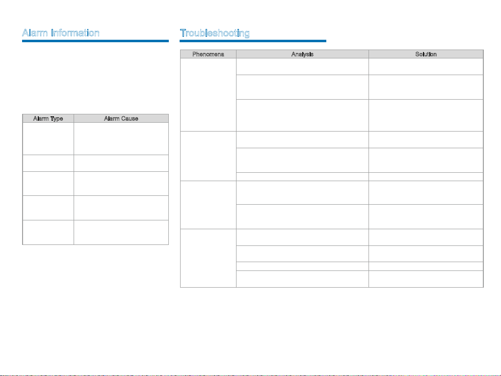
Th e r epe a te r will ha ve r ea l-t i me de t ec t io n o f its
ope rati on status auto mat ica lly. Whe n it is o peratin g
abnormally, the alarm LED indicator on the front panel
will glow red until all alarms are eliminated.
When an a larm event occurs, you can d iagno se and
solve the problem via the RDAC application provided by
us or contact your local dealer for technical support.
Alarm types and cau
Alarm Type Alarm Cause
Abnormal External
Power
High Temperature
Abnormal VSWR
TX Unlock
RX Unlock
ses are as listed below:
High Voltage: The input voltage is
higher than 15.8V±0.2V.
Low Voltage: The input voltage is
lower than 10.8V±0.2V.
Tempe rat ur e sen so r det ec ts the
temperature above 85℃.
VSWR > 3:1.
Over-high VSWR will damage the
PA module or even disable it.
T X PL L i s un lo ck e d, an d t h e
re pea te r st op s tr ansmi tt in g an d
repeating.
R X P
L L is unl oc ke d, an d th e
re pe a t er st o ps re c ei vi n g an d
repeating.
Phenomena Analysis Solution
Power-on Failure.
The radio is unable
to communicate with
other members.
There’s RX
indication on
the radios, but
members cannot
communicate with
each other.
Short
communication
distance and poor
voice quality
If the above solutions cannot fix the problems, or you have other questions, please contact Hytera or the dealer for
more technical support.
The power cord may be disconnected or not
securely connected to the outlet.
The fuse in the power cord is damaged.
DC power supply voltage is not within the
operating voltage of the repeater.
TX/RX frequency of the repeater is inconsistent
with that of portable/mobile radios.
The repeater failed to repeat useful signal due to
strong interference sig
The radio is out of the coverage of the repeater. Move into the coverage of the repeater.
Radio ID does not match that of other members. Sets the same ID with other members.
The CTCSS/CDCSSs of the radios are not
consistent.
Signal loss due to connecting cable damage.
The antenna and cable are in loose connection or
disconnected.
Internal dam
The duplexer (if installed) may be adjusted
improperly.
nals.
age of the cable. Replace the cable.
Properly connect the power cord and
ensure secure connection.
Check whether the DC power fuse is
damaged. If it is damaged, replace it with a
new one.
Check whether the DC power supp
voltage is within the operating voltage of
the repeater (13.6V±15%). If not, adjust it
to proper range.
Check if the frequencies are consistent.
Reset the frequencies when necessary.
If you cannot remove or bypass the
interference source, change to operate at
other frequencies.
Check whether the CTCSS/CDCSSs are
consistent. Reset the CTCSS/CDCSSs
when necessary.
Check whether the damage is serious.
Replace the cable when necessary.
Secure the connection. Replace the
connector when necessary.
Contact Hytera or the local dealer to readjust the duplexer.
ly
4
Page 9
Care and Cleaning
Optional Accessories
To gua rante e optimal performan ce as well as a long
service life of the product, please follow the tips below.
Product Care
●
Keep the product in good environmental conditions
to ensure reliability.
●
Do not place other equipment on top of the product
to ensure optimal heat dissipation.
●
Do not pierce or scrape the product.
●
Keep the product far away from substances that can
corrode the circuit.
●
Do no t pla ce th e p ro duc t in cor ro siv e age nts,
solutions or water.
Product Cleaning
Caution: Be sure to turn off the product
before cleaning.
●
Remove the dust and fi ne particles on the product
surface with a clean and dry lint-free cloth or a brush
regularly.
●
Us e a no n-wo ven fa br ic wit h neu tra l cle a ns er
to cl ea n t he co nn ect or s. D o n ot us e c he mic al
pr ep ara ti ons suc h a s st ain rem ove rs, al co ho l,
sprays or oil preparations. Make sure the product is
completely dry before use.
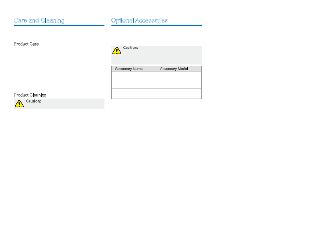
The following items are the main optional accessories
fo r th e re pe at er. Fo r mo re i nf or ma ti on of ot he r
accessories, please consult your local dealer.
Caution: Use the accessories specified by
Hytera only. If not, the Company shall not
be liable for any loss or damage arising
out of use of unauthorized accessories.
Accessory Name Accessory Model
Wall-mount Bracket BRK21
Duplexer Kit
Dup lexer Mounti ng
Bracket
●
DK08(400 - 470MHz)
●
DK09(136 - 174MHz)
BRK22
5
Page 10
2013
L07157 Z07639
811 RD6 200 000 0
2013 Hytera Corp., Ltd.
#
: !"
$%:518057
&
'(): -
400 830
.http://www hytera com.
9108
-7020
 Loading...