

Page 1

Table of contents
HYTERA MD78x Series
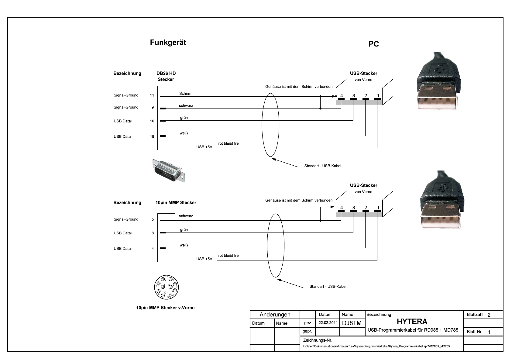
1.5 Programming cabel MD785x
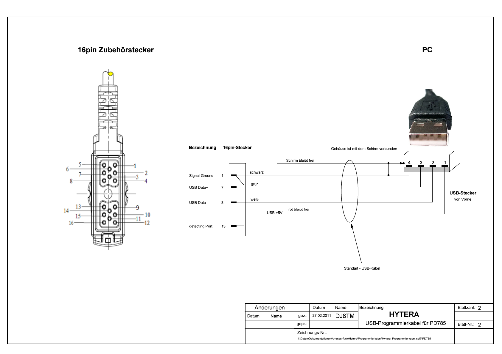
1.6 Programming cabel PD78x
1.5 Programming cable MD78x layout
1.6 Programming cable PD78x layout
Table of contents
1 Appearance and Definition ........................................................................................ 4
1.1 Appearance and Definition of 10-pin Interface................................................... 4
1.1.1 Appearance................................................................................................. 4
1.1.2 MMP 10 pin definition ................................................................................. 5
1.1.3 MMP 10 electrical specifications................................................................. 6
1.1.4 Definition of MMP10 Accessory Identifier: .................................................. 6
1.2 Appearance and Definition of 26-pin Interface................................................... 7
1.2.1 Appearance................................................................................................. 7
1.2.2 MAP 26 pin definition ..................................................................................7
1.2.3 MAP 26 electrical specifications ................................................................. 9
1.2.4 MAP accessory detection definition (rear)................................................ 10
1.3 Note.................................................................................................................. 10
1.4 Supplementary ................................................................................................. 10
90Hytera_ENG – V1.0 III
Page 2

Appearance and Definition
1 Appearance and Definition
1.1
1.1.1
Appearance and Definition of 10-pin Interface
Appearance
Figure 1: 10-pin MMP Interface on the Front Panel
Figure 2: 10-pin Socket
Figure 3: 10-pin Plug
90Hytera_ENG – V1.0 4
Page 3

Appearance and Definition
1.1.2
MMP 10 pin definition
Item Name Type Description
1
2 PTT input Digital input
3
4 USB_D/serial
5 GND Grounding differential input (together with MIC
6 USB_VBUS Power supply
Accessory
detection
interface 1
Handset audio
output
port RX
Digital input PIN1 and PIN 10 are both for
accessory detection ; for detailed
information, see “ accessory
detection interface definition”
Palm microphone PTT input;
Low level input when pressing PTT
Analogue out
USB data
cable/input port
put When accessory detection
code is 00/01/10, the audio
output is open; When it is 11,
the audio output is closed.
Used for DMR USB cable D
input)
+5V power supply, limited current
500mA; When the accessory
detection code is 00/01/10, it output
5V voltage. When the accessory
detection code is 11, it
output low level voltage.
7 MIC_INPUT Analogue input Palm microphone input,
Vrms=80mV@60% system max.
deviation
8
9 HOOK HOOK signal input
10
USB_D+/serial port
TX
Accessory
detection
interface 2
USB data cable/
output port
Digital input PIN1 and PIN 10 are both for
Used for DMR USB cable D+
Default: high level
Active : low level
Hook or Monitor function:
when press monitor on desktop mic
or hook the palm microphone, high
level will change into low level. If
palm microphone/ palm microphone
with keypad is detected, it is hook
function; if desktop microphone is
detected,
accessory detection ; for detailed
information, see “ accessory
detection interface definition”
90Hytera_ENG – V1.0 5
Page 4

Appearance and Definition
1.1.3
MMP 10 electrical specifications
Item Name Type Description
1
2 PTT input Digital input 3.3V CMOS voltage level standard
3
4 USB_D/serial
5 GND Grounding
6 USB_VBUS Power supply 5V power supply 500mA
7 MIC_INPUT Analogue input Vrms=80mV@60% system max.
8
9 HOOK HOOK signal input 3.3V CMOS voltage level standard
10
Accessory
detection
interface 1
Handset audio
output
port RX
USB_D+/serial port
TX
Accessory
detection
interface 2
Digital input 3.3V CMOS voltage level standard
Analogue out Load resistor > 1k ohm, Vrms =
600mV
USB data
cable/input port
USB data cable/
output port
Digital input 3.3V CMOS voltage level standard
3.3V CMOS voltage level standard
deviation
3.3V CMOS voltage level standard
1.1.4
Definition of MMP10 Accessory Identifier:
PIN1 PIN10 Accessory detection definition
0 0 obligated
0 1 Mobile radio is in USB host mode, accessory is in device mode;
connect to USB intelligent accessory( such as digital palm microphone)
1 0 Desktop MIC ( including desktop microphone with earpiece)
1 1 Mobile radio is in USB device mode, accessory is in host mode/ not
connected to any accessory/connect to palm microphone series
(default: ordinary palm microphone
90Hytera_ENG – V1.0 6
Page 5
Appearance and Definition
1.2
1.2.1
Appearance and Definition of 26-pin Interface
Appearance
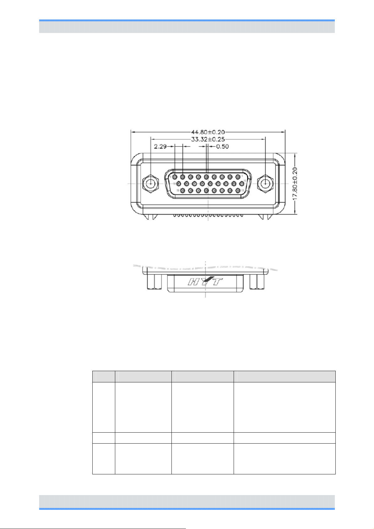
Figure 4: 26-pin connector socket
1.2.2
Figure 5: 26 MAP at rear panel
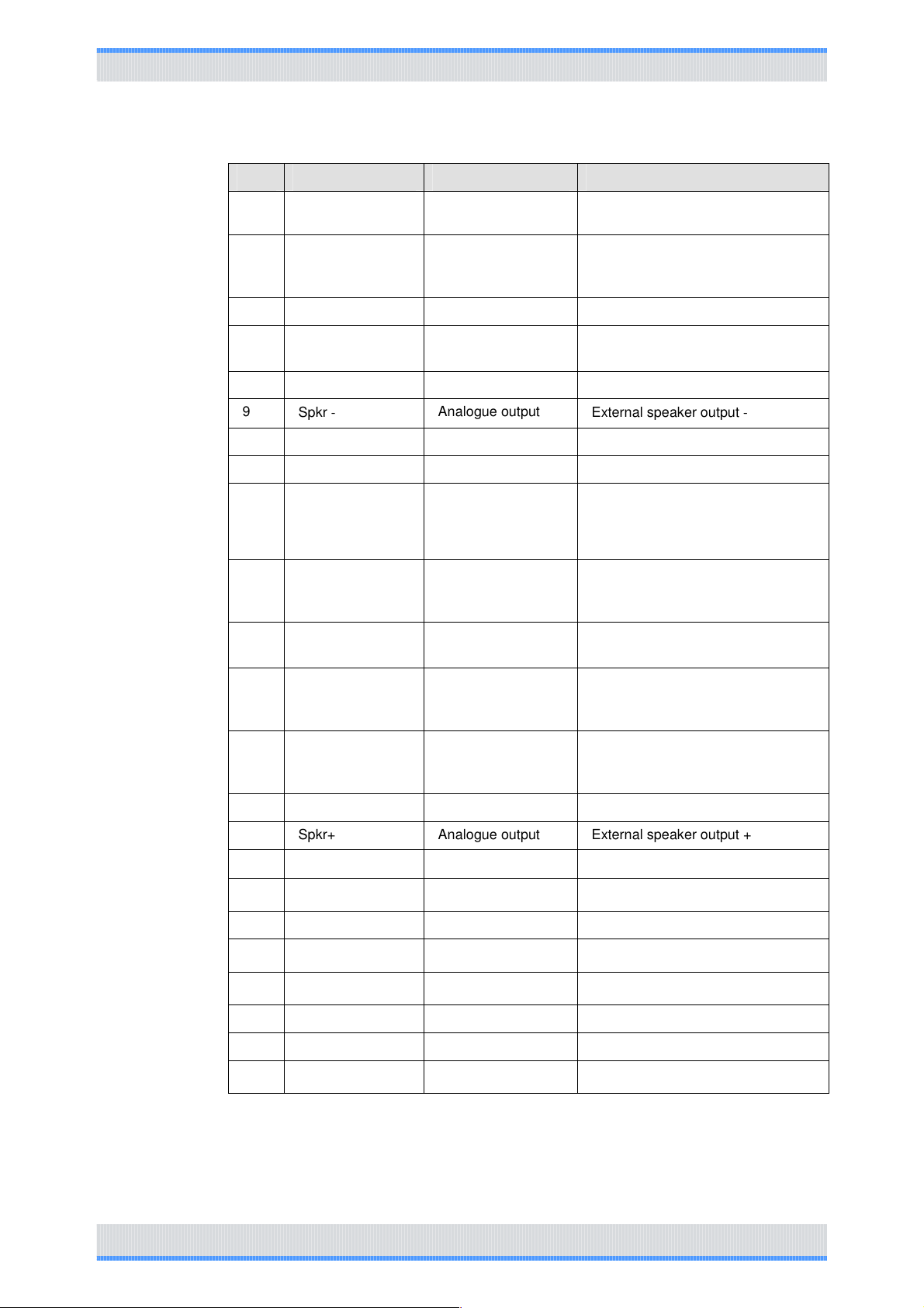
MAP 26 pin definition
Item Name Type Description
1
2 GND Grounding
3
Vbus USB power
supply
GP5_3 universal
input/output port
(chan_Act)
Power supply
Digital
input/output
+5V power supply, limited
current 500mA; When the
accessory detection code is
00/01/10, it output 5V
voltage. When the accessory
detection code is 11, it
output low level voltage.
Universal input/output port.
The functionality is configured by
CPS
90Hytera_ENG – V1.0 7
Page 6
Appearance and Definition
Item Name Type Description
4
SW B+ sense
power output
Power supply 13V power supply output;
output current <=1.5A
5 External alarm Analogue voltage
output
6 Power Ground Power ground
7
8
9
10 D+ USB USB data cable + USB data cable +
11 USB_GROUND USB_GROUND USB_GROUND
12
13 ACC_IO2 Digital input Accessory detection interface (rear);
14 Emerg SW Digital input When emergency is effective, this
15 ACC_IO3 Digital input Accessory detection interface (rear);
Tx Audio input (
external MIC audio)
Rx Audio output Analogue output
Spkr ‐
GP5_2 universal
input/output pin
(Monitor)
Analogue input External MIC signal input(rear);
Analogue output
Digital input/output
Programmable output pin (default:
external alarm, the output pin can be
configured by CPS)
active when external PTT is pressed
Rx audio signal output
External speaker output ‐
Universal input/output pin ( default:
monitor ; the pin can be configured by
CPS)
see accessory detection interface
definition(rear)
pin inputs low level
see accessory detection interface
definition(rear)
16 PRGM_IN_PTT Digital input Programmable output pin (default:
PTT; low level active; the input pin
can be configured by CPS)
17 Audio ground Audio ground
18 Spkr+ Analogue output External speaker output +
19
20
21 Ground Ground
22
23
24 AUX audio out 1 Analogue output
25 AUX audio out 2 Analogue output
26 Ign Sens
D‐USB USB data cable ‐ USB data cable ‐
GP5_8 universal
input/output pin
GP5_7 universal
input/output pin
GP5_6 universal
input/output pin
output/input Universal input/output pin
output/input Universal input/output pin
output/input Universal input/output pin
Analogue voltage
input
Ignition sense input pin
90Hytera_ENG – V1.0 8
Page 7
Appearance and Definition
1.2.3
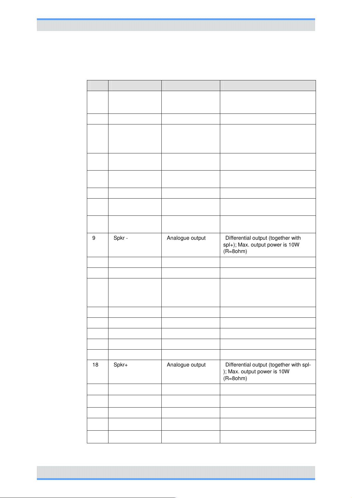
MAP 26 electrical specifications
Item Name Type Description
1
2 GND Grounding
3
4
5 External alarm Analogue voltage
6 Power Ground Power ground
7
8
9
Vbus USB power
supply
GP5_3 universal
input/output port
(chan_Act)
SW B+ sense
power output
Tx Audio input (
external MIC audio)
Rx Audio output Analogue output
Spkr ‐
Power supply +5V power supply output
Digital
input/output
Power supply
output
Analogue input Vrms = 80mV@60% system max.
Analogue output Differential output (together with
5V TTL level standard
13V+15% power supply output;
output current <=1.5A
13V emergency alarm output
deviation
Load resistor > 1k ohm, Vrms
=300mV
spl+); Max. output power is 10W
(R=8ohm)
10 D+ USB USB data cable + USB data cable +
11 USB_GROUND USB_GROUND USB_GROUND
12
13 ACC_IO2 Digital input 5V TTL level standard
14 Emerg SW Digital input 5V TTL level standard
15 ACC_IO3 Digital input 5V TTL level standard
16 PRGM_IN_PTT Digital input 5V TTL level standard
17 Audio ground Audio ground
18 Spkr+ Analogue output Differential output (together with spl-
19
20
21 Ground Ground
22
23
GP5_2 universal
input/output pin
(Monitor)
D‐USB USB data cable ‐
GP5_8 universal
input/output pin
GP5_7 universal
input/output pin
GP5_6 universal
input/output pin
Digital input/output
output/input 5V TTL level standard
output/input 5V TTL level standard
output/input 5V TTL level standard
5V TTL level standard
); Max. output power is 10W
(R=8ohm)
USB data cable
90Hytera_ENG – V1.0 9
Page 8
Appearance and Definition
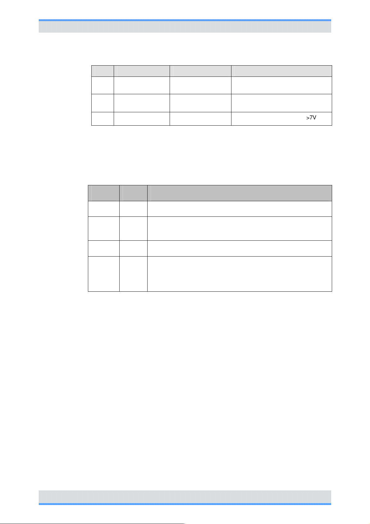
Item Name Type Description
24 AUX audio out 1 Analogue output
25 AUX audio out 2 Analogue output Load resistor >1k ohm, Vrms
26 Ign Sens
Note: CPS = computer programming software
Analogue voltage
input
Load resistor >1k ohm, Vrms
=300mV
=300mV
Ignition sense input voltage >7V
1.2.4
1.3
MAP accessory detection definition (rear)
PIN1 PIN10 Accessory detection definition
0 0 Programming cable
0 1 Mobile radio is in USB host mode, accessory is in device mode;
connect to USB intelligent accessory
1 0 External speaker
1 1
Mobile radio is in USB device mode, accessory is in host mode/ not
connected to any accessory/connect to palm microphone series
(default:
ordinary palm microphone
Note
1. Front panel PTT, rear PTT, front panel MIC and rear MIC can be opened by CPS
freely. Default: front panel PTT and front panel MIC is opened
1.4
90Hytera_ENG – V1.0 10
Supplementary
5V TTL level standard
TTL high level: 3.6 – 5V, low level: 0 – 2.4 V
Output L: <0.8V; H: >2.4V
Input L: <1.2V; H: > 2.0V
TTL output low level should be less than 0.8V, while high level should be more
than 2.4V.
Page 9

Appearance and Definition
TTL input is 0 when input level is less than 1.2, and 1 when input level is more
than 2.0.
3.3V CMOS level standard
Vcc : 3.3V
VOH > = 3.2V; VOL <=0.1V
VIH >= 2.0V; VIL <= 0.7V
Note : “VIH” = high level of input voltage
“VIL” = low level of input voltage
“VOH” = high level of output voltage
“VOL” = low level of output voltage
90Hytera_ENG – V1.0 11
Page 10
1.5
Page 11
1.6
 Loading...