

Page 1

is the tradem ar k of H yt er a Co mmunicati on s Co rp ., L td .
2010 Hytera C or p. , Lt d. Al l Ri ghts Reserv ed .
Address: HY T Tower, Hi-Tech I nd us tr ia l Pa rk North, Bei hu an
RD ., N an sh an D is trict, Shen zh en , Ch in a
Postcode: 51 80 57
http:// ww w.h yt er a. cn
811MD78000010
TM
OWNER’ S MANUAL
DMR MOBILE RADIO
2010 Hytera C or p. , Lt d
X05031
Page 2

Preface
Thank you for purchasing Hytera DMR Digital Mobile Radio. As a product built
to the DMR standard, It is endowed with ergonomic design, all-round digital
functions and remarkable quality to increase your management efciency and
enable you to be responsive to emergent situations.
To derive optimum performance from your product, please read this manual
and the supplied Safety Information Booklet carefully before use.
The manual is applicable to the following model:
MD78X
MD78XG
Page 3
Instructional Icons
The following icons are available through this manual:
Alert Icons
Caution: indicates situations that could cause
damage to your product.
Note: indicates tips that can help you make better use
of your product.
Function Icons
: indicates functions that are available on digital
channel only.
: indicates functions that are available on analog
channel only.
Func tions marked with no functi on icons are available on both
analog and digital channels.
Term Explanation
Key Operation
Short press: to press a key and release it quickly.
Long press: to press a key and remain holding it down for a pre-
dened period (2 seconds by default).
Hold down: to press a key and remain holding it down.
Private Call
Private Cal is a call initiated by a single user to another user.
Group Call
Group Call is a call initiated by a single user to a group.
All Call
All Call is a call initiated by a single user to all the other users on a
channel.
Squelch
This technology can remove excessive background noises, improv-
ing your communication quality.
PTT ID
PTT ID, namely radio identity, allows a radio with display or the
control center to identify the calling party.
Page 4

Copyright Information
Hytera and HYT a re trad em ar ks or re gi st er ed tra de ma rk s of
Hytera Communications Co., Ltd. (“Hytera”) in PRC and/or other
countries or areas. Hytera retains the ownership of its trademarks
and product names. All other trademarks and/or product names
that may be used in this manual are properties of their respective
owners.
The Hytera product described in this manual may include Hytera
comp uter program s sto red in memory or other media. Laws in
PRC and/or other countries or areas protect the exclusive rights
of Hytera with respect to its computer programs. The purchase
of this product shall not be deemed to grant, either directly or by
implica tion, an y rights to the purchaser with respec t to Hytera
computer programs. Any Hytera computer programs may not be
copied, modied, distributed, decompiled, or reverse-engineered in
any manner without the prior written consent of Hytera.
The AMBE+2
is protected by intellectual property rights including patent rights,
copyrights and trade secrets of Digital Voice Systems, Inc.
This voice coding technology is licensed solely for use within this
product. The user of this technology is explicitly prohibited from
attempting to decompile, reverse engi neer, or d isassemble the
Object Code or in any other way convert the Object Code into a
human readable form.
U.S . Patent Nos. #6,912,495 B2, #6 ,19 9,037 B1, #5,870,4 05,
#5,826,222 , #5,754 ,97 4, #5,70 1,3 90, #5,715,365, #5,649 ,05 0,
#5,630,011, #5,58 1,6 56, #5,517,511, #5 ,49 1,7 72, #5,247,579,
#5,226,084 and #5,195,166.
TM
voice coding technology embodied in this product
Disclaimer
Hytera endeavors to achieve the accuracy and completeness of
this manual, but no warranty of accuracy or reliability is given. All
the specications and designs are subject to change without prior
notice due to continuous technology development. No part of this
manual may be copied, modied, translated, or distributed in any
manner without the express written permission of Hytera.
If you have any suggestions or would like to learn more details,
please visit our website at:http://www.hytera.cn.
Page 5
RF Radiation Information
RF Radiation Prole
Radio Frequency (RF) is a frequency of electromagnetic radiation
in the range at which radio signals are transmitted. RF technology
is widely used in communication, medicine, food processing and
other elds. It may generate radiation during use.
RF Radiation Safety
In order to ensure user health, experts from relevant industries
incl uding scienc e, engineeri ng, medici ne and health work with
international organizations to develop standards for safe exposure
to RF radiation. These standards consist of:
United States Federal Communications Commission, Code of
Federal Regulations; 47CFR part 2 sub-part J;
American National Standards Institute (ANSI)/Institute of Elec-
trical and Electronic Engineers (IEEE) C95. 1-1992;
Institute of Electrical and Electronic Engineers (IEEE) C95. 1 –
1999;
International Commission on Non-Ionizing Radiation Protection
(ICNIRP) 1998.
FCC Regulations
Federal Co mm un ic at io n Commission (F CC ) re qu ir es that al l
radio communication products should meet the requirements set
forth in the above standards before they can be marketed in the
U.S, and the manufacturer shall post a RF label on the product
to inform users of operational instructions, so as to enhance their
occupational health against exposure to RF energy.
As a consc ien tio us company centering on users, Hyt era str ict ly
complies with the foregoing requirements from design, production
and test.
EU Regulatory Conformance
As certied by the qualied laboratory, the product is in compliance
with the essential requirements and other relevant pr ovisions of
the Directive 1999/5/EC. Please note that the above information is
applicable to EU countries only.
Page 6
Contents
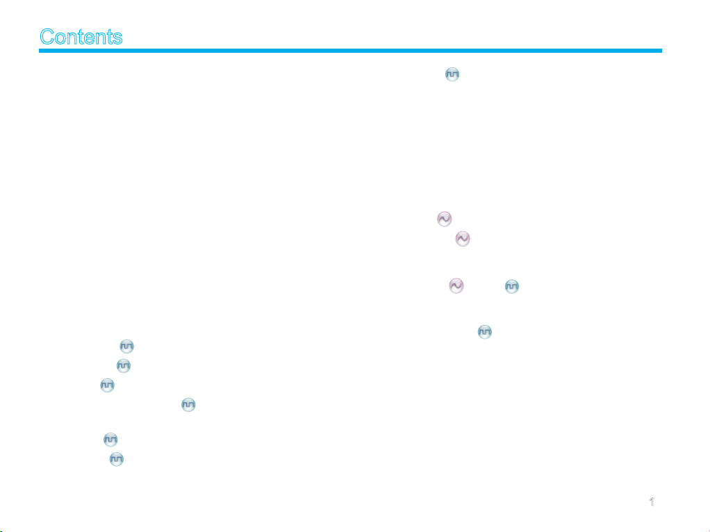
Checking Items in the Package -------------------------------2
Product Overview ------------------------------------------------- 3
Front Panel -----------------------------------------------------------3
Rear Panel---------------------------------------------------------------------3
Programmable Keys ------------------------------------------------4
Installation ---------------------------------------------------------- 5
Instructions ------------------------------------------------------------5
Installation Tools -----------------------------------------------------5
Installation Steps ----------------------------------------------------6
Status Indication -------------------------------------------------- 7
LCD Icon --------------------------------------------------------------7
LED Indicator ---------------------------------------------------------8
Basic Operations -------------------------------------------------- 9
Turning the Radio On/Off ------------------------------------------9
Adjusting the Volume -----------------------------------------------9
Selecting a Zone ----------------------------------------------------9
Selecting a Channel ------------------------------------------------9
Switching the Channel Mode -------------------------------------9
Call ----------------------------------------------------------------- 10
Private Call ------------------------------------------------------10
Group Call -------------------------------------------------------10
All Call ------------------------------------------------------------11
Calls on Analog Channels -----------------------------------11
Menu Navigation -------------------------------------------------- 12
Contact -----------------------------------------------------------12
Message ----------------------------------------------------------12
Call Logs
Scan ------------------------------------------------------------------- Zone --------------------------------------------------------------------14
Settings ----------------------------------------------------------------14
Accessories -----------------------------------------------------------16
---------------------------------------------------------13
14
Functions and Operations -------------------------------------- 17
Home Screen ---------------------------------------------------------17
Scan --------------------------------------------------------------------17
Public Address -------------------------------------------------------17
Talk Around -----------------------------------------------------------18
Monitor
Squelch Off
Emergency ----------------------------------------------------------- Ignition Sense --------------------------------------------------------21
Scrambler
Busy Channel Lockout -------------------------------------------- Time-out Timer (TOT) ----------------------------------------------22
Pseudo Trunking
MIC AGC ------------------------------------------------------------- Emergency Footswitch ---------------------------------------------23
Channel Steering ----------------------------------------------------23
------------------------------------------------------------18
------------------------------------------------------18
18
/Encrypt ---------------------------------------22
22
-----------------------------------------------22
23
Signaling Introduction -------------------------------------------- 24
HDC1200 --------------------------------------------------------------24
Troubleshooting --------------------------------------------------- 25
Care and Cleaning ----------------------------------------------- 26
Optional Accessories -------------------------------------------- 27
Appendix ------------------------------------------------------------ 28
Input Method ---------------------------------------------------------28
1
Page 7
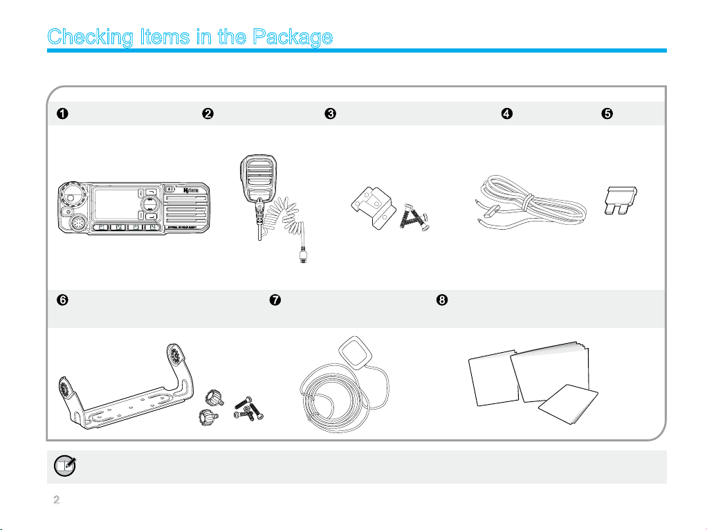
Checking Items in the Package
Please unpack carefully and check that all items listed below are received. If any item is missing or damaged, please contact your dealer.
Radio Unit Palm Microphone Microphone Hanger and Screws Power Cord Fuse
Mounting Bracket Kit GPS Antenna Owner’s Manual /Quick Reference Guide/Safety
Information Booklet
Owner’s Manual
Safety Information Booklet
Quick Reference Guide
Note: To realize functions enabled by inputting, please purchase a palm microphone with keypad. Go to Optional
Accessories for more details.
2
Page 8
Product Overview
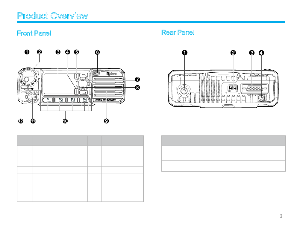
Front Panel
No. Part Name No. Part Name
Volume Control / Channel
1
Selector Knob
3 LCD Display 4 OK/Menu Key
5 Back Key 6 Power On/Off Key
7 Up Key 8 Down Key
9 Speaker 10
11 Microphone Jack 12
2 LED Indicator
P r o g ra m m ab l e
Keys
Microphone Instal-
lation Index
Rear Panel
No. Part Name No. Part Name
RF Antenna Connec-
1
tor
3 Accessory Jack 4
2 Power Inlet
G P S A n t e n n a
Connector
3
Page 9
Product Overview
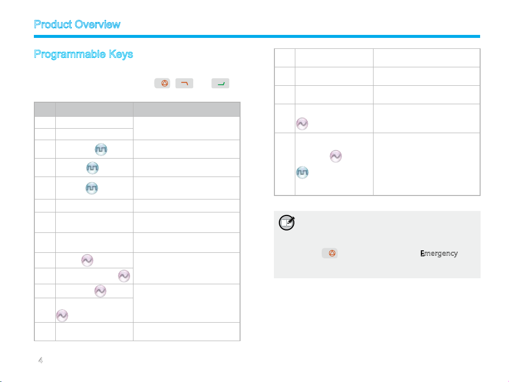
Programmable Keys
For en hanced conv enience , you may re qu es t your dealer to
pr og ra m t he keys P1 , P 2, P3, P4, , and a s
shortcuts to the functions listed below:
No. Shortcut Keys Description
1 Zone Up
2 Zone Down
3 Contact List
4 Message
5 Call Log
6 Adjust Power Level To adjust power level quickly
7 Public Address
8 Talk Around
9 Monitor
10 Monitor Momentary
11 Squelch Off
Squelch Off Momentary
12
13 Home Screen
To select a desired zone quickly
To access the menu “Contact List”
quickly
To access the menu “Message”
quickly
To access the menu “Call Logs”
quickly
To make public address via the
external speaker quickly
To directly communicate with
other radios
To adjust the condition for
incoming signal match
To always unmute speaker no
matter whether carrier is present
or not
To quickly return to the previous
menu or home screen
14 Scan
Nuisance Temporary
15
Delete
16 Emergency
Adjust Squelch Level
17
Scrambler /Encrypt
18
Note:
1 L ong an d shor t p ress of a key ca n be
assigned with different functions by your
dealer.
2
is programmed as the Emergency key
by default, and is programmable by your
dealer.
To receive signals on other
channels
To temporarily ignore unwanted
channel activity
To summon help in emergent
situations
To temporarily adjust the squelch
threshold required for the radio to
unmute
Scrambler: To encrypt your voice
so as to guarantee privacy of your
communication
Encrypt: To encrypt your voice
and message so as to guarantee
privacy of your communication
4
Page 10
Installation
Befor e yo u inst al l th e ra di o in a v eh icle, be su re to rea d the
following instructions carefully:
Instructions
The radio operates with cathode-grounded power supply of
13.6V ± 15% only. Please check polarity and voltage of the
power supply on the vehicle before you install the radio.
Please check how long the screws will extend from the bot-
tom surface of the radio, before you install the radio. Drill the
mounting hole cautiously to avoid damage to the vehicle wiring
and other parts.
Please connect Hytera supplied antenna and power cord to
the radio, before you install it in the bracket. And make sure
the antenna and power cord is dedicated for Hytera digital
radios.
Install the radi o wit h Hyt era supplied mounting bracket, to
avoid radio looseness in case of accidents. The loose radio
may cause bodily injury.
Install the radio in a location where it’s easy to reach the front
panel controls.
Please make sure there’s sufcient space at back of the radio
for wiring.
When the fuse for DC power cord needs replacement, it must
be replaced by a fuse with the same specication.
Installation Tools
Electric drill
Cross head screwdriver
Hex socket sleeve (used for 4.8*20mm self-tapping screws)
5
Page 11
Installation
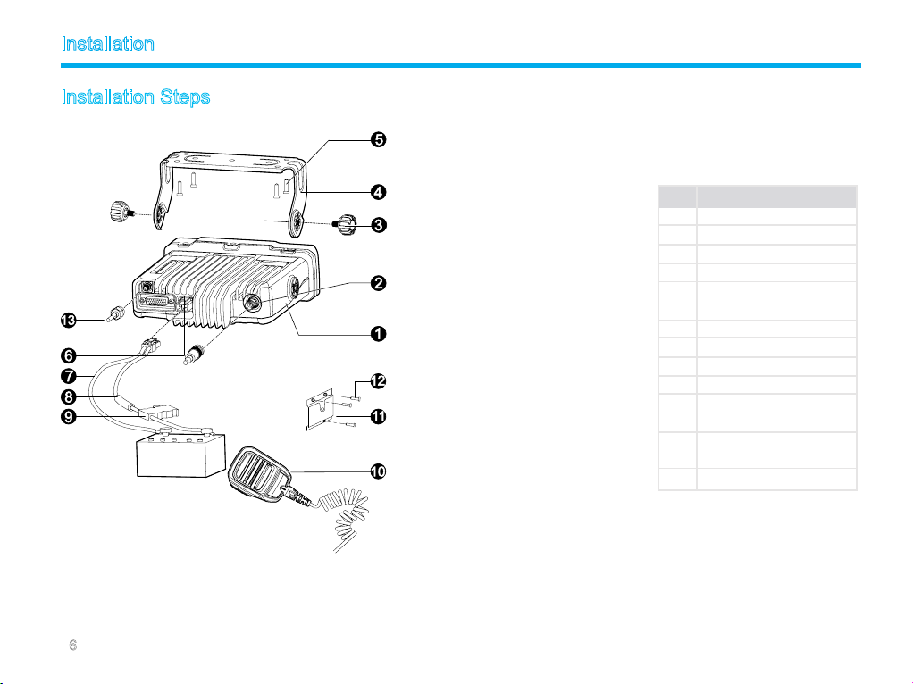
Installation Steps
A Install th e bracket i n a l ocation
wh e r e it’s ea s y to o p era t e th e
radio.
B Con ne ct ac cess ories such as
ant enn a an d po wer cord to the
radio.
C Slide the radio into the mounting
br ac ket and sec ur e i t usi ng the
locking knobs.
D Install the microphone hanger
a location where it can be reached
easily.
E Plu g the palm micr ophon e into
the microphone jack on the front
panel (but at rst align the triangle
index on the palm microphone with
the microphone installation index),
and place it o n the hanger when
you do not use it.
in
No. Part Name
1 Radio Unit
2 RF Antenna Connector
3 Locking Knobs
4 Mounting Bracket
5 4.8 * 20 mm Self-
tapping Screws
6 Power Inlet
7 Black Power Cord
8 Red Power Cord
9 Fuse
10 Palm Microphone
11 Microphone Hanger
12 4 * 16 mm Self-tapping
Screws
13 GPS Antenna Connector
6
Page 12
Status Indication
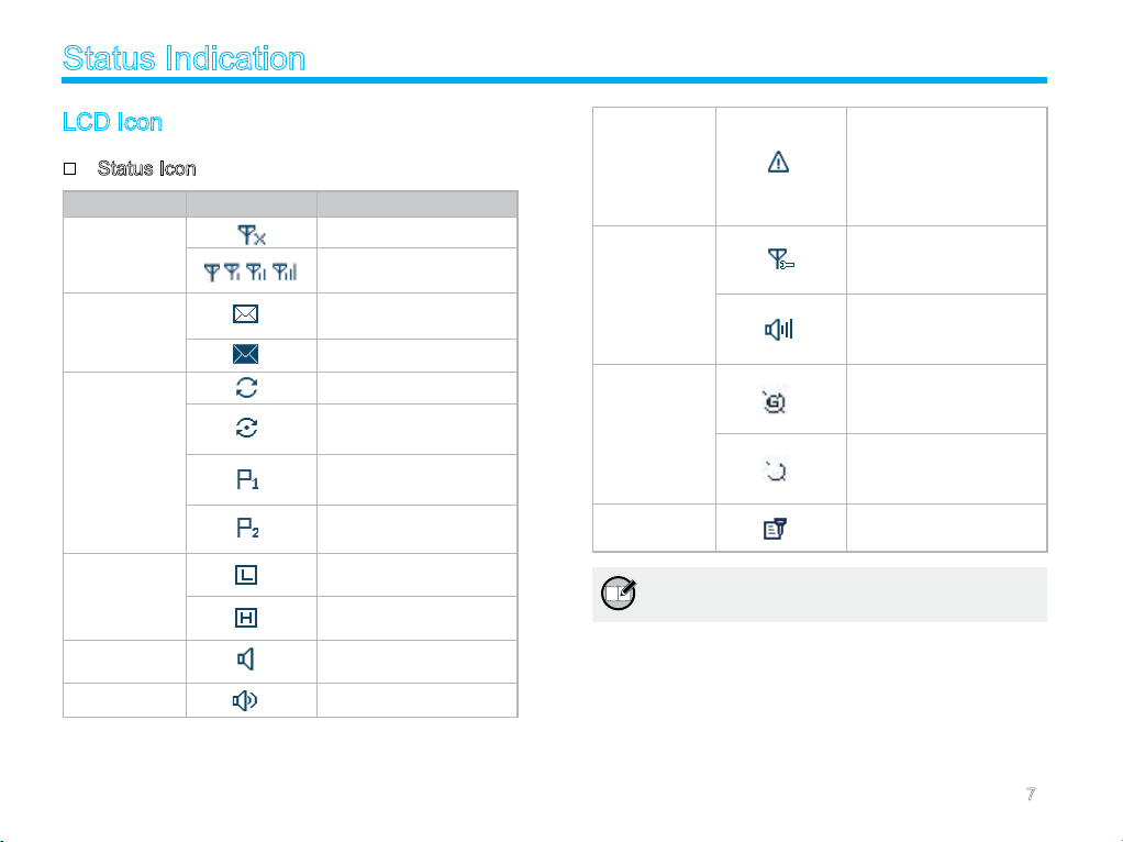
LCD Icon
Status Icon
Icon Name Icon Radio Status
No signal
RSSI
Message Icon
Scan Icon
TX Power
Icon
Monitor Icon
Speaker Icon The speaker is unmuted
More bars indicate better
signal strength
New message/unread
message
InBox is full
Scanning is in progress
Scanning pauses on a
non-priority channel
Scanning pauses on
Priority Channel 1
Scanning pauses on
Priority Channel 2
Low TX power for the
current channel
High TX power for the
current channel
The Monitor feature is
active
The Emergency mode
Emergency
Icon
Knob
Operation
Mode Icon
GPS Icon
Scrambler/
Encrypt Icon
Note: The description related to the GPS feature in
this manual is applicable to MD78XG only.
(other than secret
emergency) is active or
an emergency message
is received
The knob currently
operates in channel
selection mode
The knob currently
operates in volume
adjustment mode
The GPS feature is
active, and valid GPS
data is received
The GPS feature is
active, but no valid GPS
data is received
The Scrambler/Encrypt
feature is active
7
Page 13
Status Indication
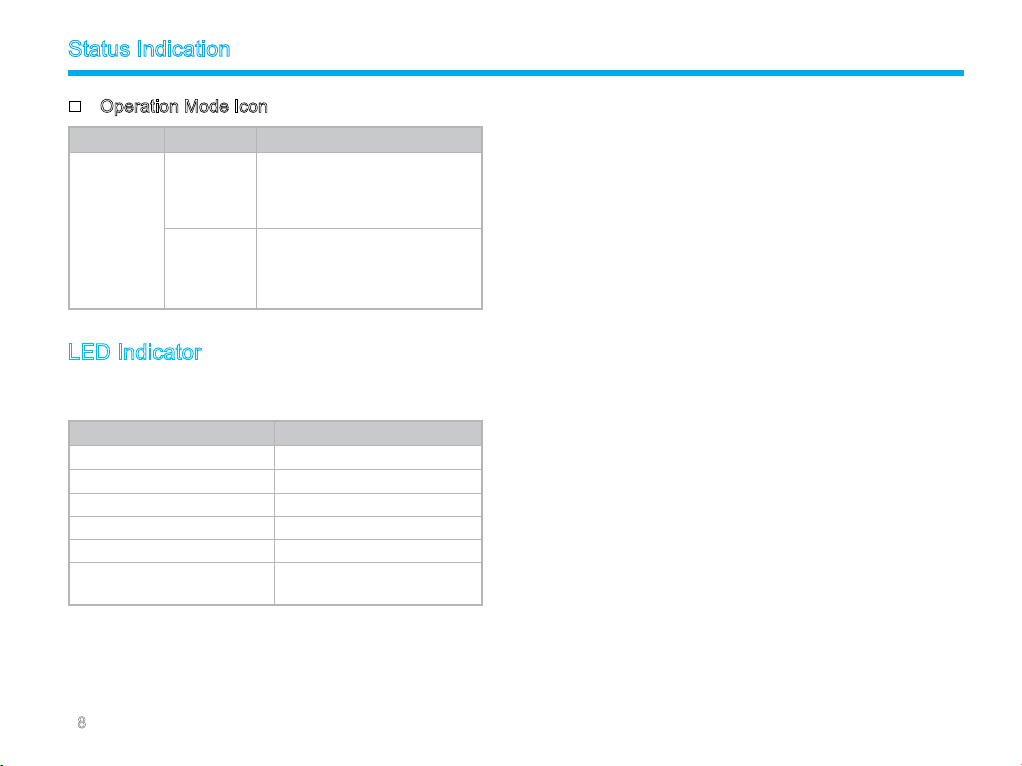
Operation Mode Icon
Icon Name Icon Operation Mode
Direct Mode: Under this mode,
DM
Operat io n
Mode Icon
RM
radios communica te with each
other directly
Repeat er Mo de : Un d e r th is
mode, radios communicate with
each other via a repeater
LED Indicator
The LED indicator will help you easily identify the current radio
status.
LED Indicator Radio Status
LED ashes green. Powering on
LED glows red. Transmitting
LED glows green. Receiving
LED ashes green slowly. Scanning
LED ashes orange rapidly. Emergency
LED glows orange.
Call ended (within the preset
time period)
8
Page 14
Basic Operations
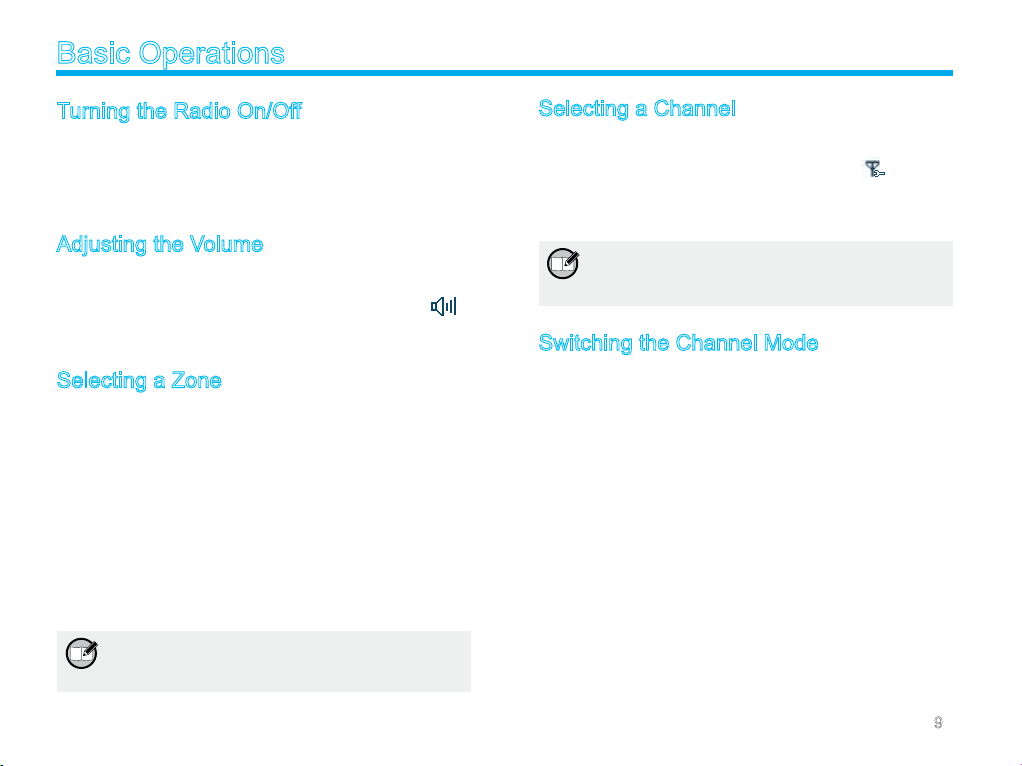
Turning the Radio On/Off
To turn the radio on, long press the Power On/Off key until the
radio shows power-up screen and sounds power-up alert, and the
LED ashes green. To turn the radio off, press the Power On/Off
key.
Adjusting the Volume
When the Volume Control / C hannel Selector knob operates
in volume adjustment mode (the radio displays the icon ),
rotate the knob clockwise to increase the call volume, or counter-
clockwise to decrease it.
Selecting a Zone
A zone is a group of channels exhibiting the same property, and is
programmed by your dealer. The radio supports up to 64 zones,
each with a maximum of 16 channels. You ma y sel ect a zone
through any of the following methods:
1. Through menu selection
Go to the menu “Zone”, and use the Up/Down key to select
your desired zone.
2. Through the function keys
You may quickly toggle to your desired zone by pressing the
programmed Zone Up or Zone Down key.
Note: You dealer may designate the powe r-up
zone and channel. If not, the radio will enter
the zone and channel last used.
Selecting a Channel
Press the Volume Control / Channel Selector knob to switch it to
channel selection mode (the radio displays the icon ), and then
rotate the knob to select your desired channel. Alias of the current
channel will appear in the home screen.
Note: The knob is in volume adjustment mode
by default, and will return to this mode in 5
seconds after you select a channel.
Switching the Channel Mode
Each channel can be programmed as either analog channel or
digital channel. If the current zone includes both analog and digi-
tal channels, you may quickly switch between digital and analog
channels through the Volume Control / Channel Selector knob.
9
Page 15
Call
To ensure optimal volume of the receiving radio, hold the palm
microphone approximately 2.5 to 5 centimeters away from your
mouth.
Private Call
Transmitting a Private Call
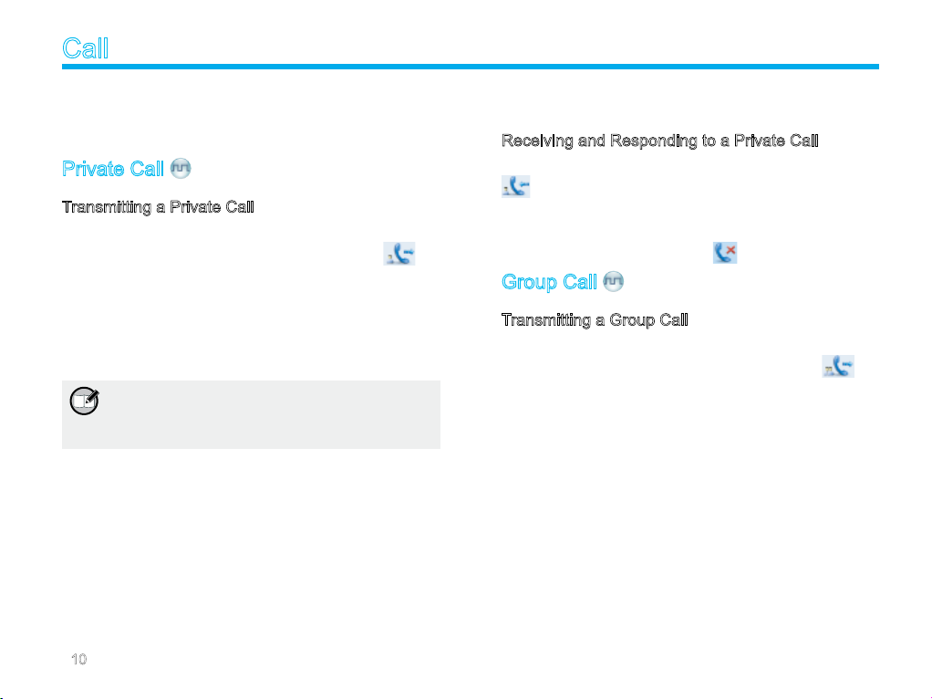
You may trans mit a Priv ate Call thro ugh any of the fo llowi ng
methods. When tr ansm itting a Private Call, the icon will
appear.
Transmitting a call to the preset contact
In the home scre en, hold down the PTT key on the pa lm
micro ph one to tran sm it a Priv at e Ca ll to the Pr ivate Call
contact preset for the current channel.
Note: Your dealer may preset a contact for each
digital channel. The preset contact could be
a Private Call contact, a Group Call contact or
an All Call contact.
Transmitting a call through Contact List or Call Logs
1 Go to “Contac t -> Conta ct List”, or g o to “Call Logs ” an d
access the Outgoing/Incoming/Missed list.
2 Use the Up/Down key to select the Private Call contact you
want to call.
3 Hold down the PTT key to transmit the Private Call.
Transmitting a call through Manual Dial
1 Go to “Contact -> Manual Dial”.
2 I npu t a Priv ate Call numb er you want to c all usin g the
microphone with a keypad.
3 Hold down the PTT key to transmit the Private Call.
Receiving and Responding to a Private Call
When a Private Call is received, your radio will display the icon
.
You may hold down the PTT key within the preset time period to
call back. If you do not respond to a received Private Call, your
radio will display the missed call icon .
Group Call
Transmitting a Group Call
You may tran sm it a G ro up Call th ro ug h an y of th e following
method s. When tr ans mitting a Group Call, the ic on w ill
appear.
Transmitting a call to the preset contact
In th e home sc reen, ho ld down the PTT key to transm it a
Group Call to the Group Call contact preset for the current
channel.
Transmitting a call through Contact List
1 Go to “Contact -> Contact List”.
2 Use the Up/Down key to select the Group Call contact you
want to call.
3 Hold down the PTT key to transmit the Group Call.
10
Page 16
Call
Receiving and Responding to a Group Call
When a Group Call is received, your radio will display the icon
.
You may hold down the PTT key within the preset time period to
call back.
All Call
Transmitting an All Call
Methods are the same as those in Transmi tting a Group Call.
When transmitting an All Call, the icon will appear.
Note: You can transmit an All Call only when it is
enabled by your dealer.
Receiving an All Call
When an All Call is received, your radio will display the icon .
Note: You cannot respond to an All Call.
Calls on Analog Channels
To transmit on an analog channel, hold down the PTT key and
speak into the microphone. To receive, release the PTT key.
11
Page 17
Menu Navigation
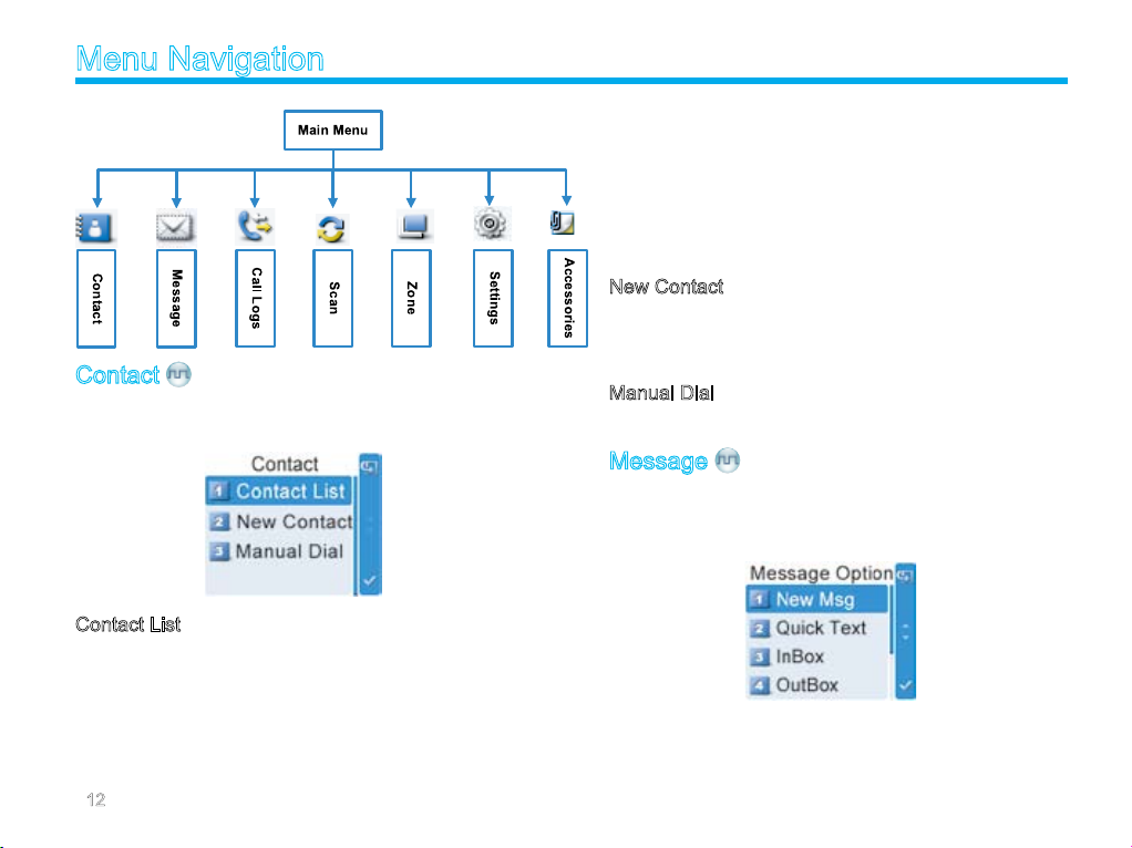
Contact
To access this item, press the Menu key in the home screen and
then select “Contact”.
Contact List
You can save up to 200 entries in the list. To access this item,
sel ect “Contact -> Contact List” or pre ss the sh ortcut key for
Contact List.
Editing a Contact
You can edit the number and alias of each Private Call contact.
Viewing a Contact
You can view details of each contact.
Deleting a Contact
You can delete a Private Call contact. However, please note that
you can not delete the contact when there is only one entry left in
the list. In addition, the Private Call contact preset on the currently
used channel cannot be deleted.
New Contact
You can add a Private Call contact to the contact list. The number
and alias of each cont act mu st be uniqu e, and the availa bl e
number range is 1-16776415.
Manual Dial
You can manually input the Private Call number for calling.
Message
To access this item, press the Menu key in the home screen and
then select “Message”, or press the shortcut key for Message
directly.
12
Page 18
Menu Navigation
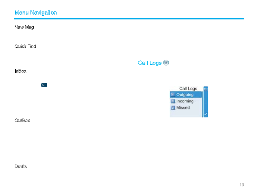
New Msg
You can create new text message (256 characters at most) and
send it to an individual user or to a talk group.
Quick Text
Under this option there are some text messages (10 entries at
most) preset by your dealer. You can choose to edit and send any
entry.
InBox
The InBox can save up to 20 received messages. When the InBox
is full, the icon will appear, and the earliest message will be
overwritten by the latest one automatically.
For each message, y ou can choo se to perform any of the se
operations: Reply, Forward, View Details and Delete.
To delete all messages in the InBox, select “Message -> InBox ->
Delete All”.
OutBox
The OutBox can save up to 20 sent messages. When the OutBox
is full, the earliest message will be overwritten by the latest one
automatically.
For each message, y ou can choo se to perform any of the se
operations: Resend, Forward, View Details and Delete.
To delete all messages in the OutBox, select “Message -> OutBox
-> Delete All”.
Drafts
The Drafts can save up to 20 draft messages. When the Drafts
is full, the earliest message will be overwritten by the latest one
automatically.
For each message, y ou can choo se to perform any of the se
operations: Send, Save and Delete.
To delete all messages in the Drafts, select “Message -> Drafts ->
Delete All”.
Call Logs
To access this item, press the Menu key in the home screen and
then select “Call Logs”, or press the shortcut key for Call Logs
directly.
This radio can save up to 10 private call entries in the Outgoing/
Incoming/Missed list respectively. When the Outgoing/Incoming/
Missed list is full, the earliest entry will be overwritten by latest one
automatically.
After accessing a list and selecting an entry, you can perform any
of these operations: hold down the PTT key to initiate a call; add it
to Contact List; or delete it.
To delete all entries in the Outgoing/Incoming/Missed list at a time,
select “Call Logs -> Outgoing/Incoming/Missed -> Delete All”.
13
Page 19
Menu Navigation
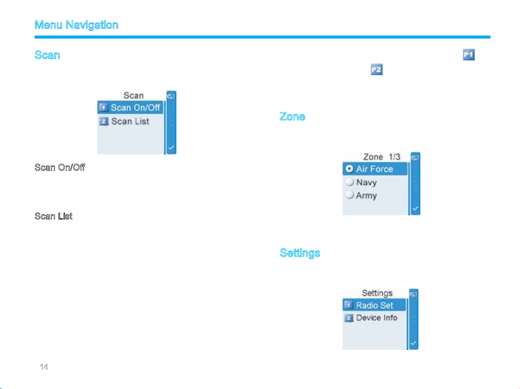
Scan
To access this item, press the Menu key in the home screen and
then select “Scan”.
Scan On/Off
The Scan feature allows you to listen to communication activities
on other channels so that you can keep a close track of your team
members. This option is used to enable or disable the function.
Scan List
You can request your dealer to create a scan list for each channel.
Each list may contain 32 channels at most (either digital channel
or analog channel is OK). After accessing the list, you can perform
any of the following operations:
Adding a Channel
To include a new channel into the active scan list.
Editing Priority Channel
To s et the se le cted chan ne l as a n on-pr io rity or as a p riori ty
channel. If you are interested in activities on a channel, you can
set it as a priority channel, which will be scanned more frequently
than a non-priority channel.
Each scan list may contain two priority channels at most. indi-
cates priority channel 1, and indicates priority channel 2.
Deleting a Channel
To remove a channel from the active scan list. However, the rst
channel in the list can not be deleted.
Zone
To access this item, press the Menu key in the home screen and
then select “Zone”.
This radio supports up to 64 zones . You can use this menu to
select your desired zone.
Settings
To access this item, press the Menu key in the home screen and
then select “Settings”.
14
Page 20
Menu Navigation
Radio Set
You can optimize your radio performance by customizing related
parameters according to actual needs and your preferences.
Power Level
This option allows you to set TX power level. Alternatively, you
can change the power level by pressing the shortcut key for Adjust
Power Level in the home screen.
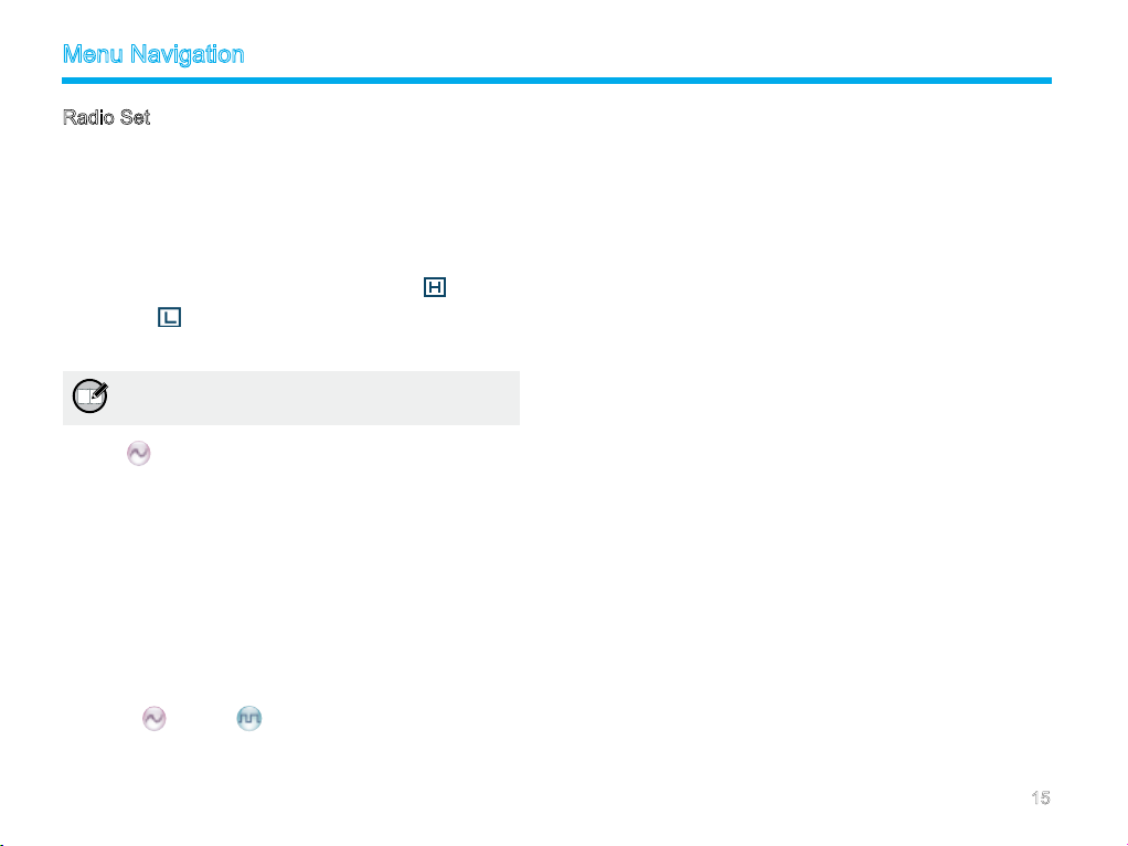
There are two levels available: High (indicated by ) and Low
(indicated by ). High power level enables you to communicate
with farther team members.
Note: Power level should be set for each channel
individually.
Squelch
This option allows you to select an appropriat e squelc h level.
Alternatively, you ca n change th e sq ue lc h level by pressing
the shortcut key for Adjust Squelch Level in the home screen.
There are three levels available: Tight, Normal and Open. The
default squelch level is “Normal”, and is often used in low noise
environment.
And generally, “Tight” is used in high noise environment. It requires
stronger signal for the radio to unmute. However, if the squelch
level is set to Open, the speaker will keep unmuted irrespective of
the decoding conditions.
Scrambler
To set whether to enable the Scrambler/Encrypt feature.
/Encrypt
Language
To set the language in which all interface information is displayed.
Backlight
To set the backlight parameters. There are three options available:
On, Off and Timer. The timer is programmed by your dealer, with
an available duration of 5-60 seconds.
Brightness
To set the display brightness. You can raise or lower it using the
Up/Down key.
LED
To set whether to enable LED indication.
Tone
To set alert tones for your radio. You can set the following tones:
Radio Silent: to set whether the radio will give tone indication. If
Silent On is selected, all tone indication will be cancelled.
Talk Permit: to set whether the radio will give tone indication for
tran smissio n. The fol lowing options are available: Dis able (no
tone indication for transmission), Digital Only (tone indication for
transmission on digital channels only), Analog Only (tone indication
for tran smi ssion on analo g ch ann els only) , an d En able (ton e
indication for transmission on both analog and digital channels).
Private Ring: to set whether the radio will give tone indication when
it receives a private call.
TextMsg Ring: to set whether the radio will give tone indication
when it receives a message.
Keypad: to set whether the radio will give tone indication when you
are making keypad operations.
15
Page 21
Menu Navigation
Device Info
With this option, you can view basic informat ion of your ra dio,
in cl udi ng ser ial num be r, radio mod el , frequ en cy ra nge and
rmware version, etc.
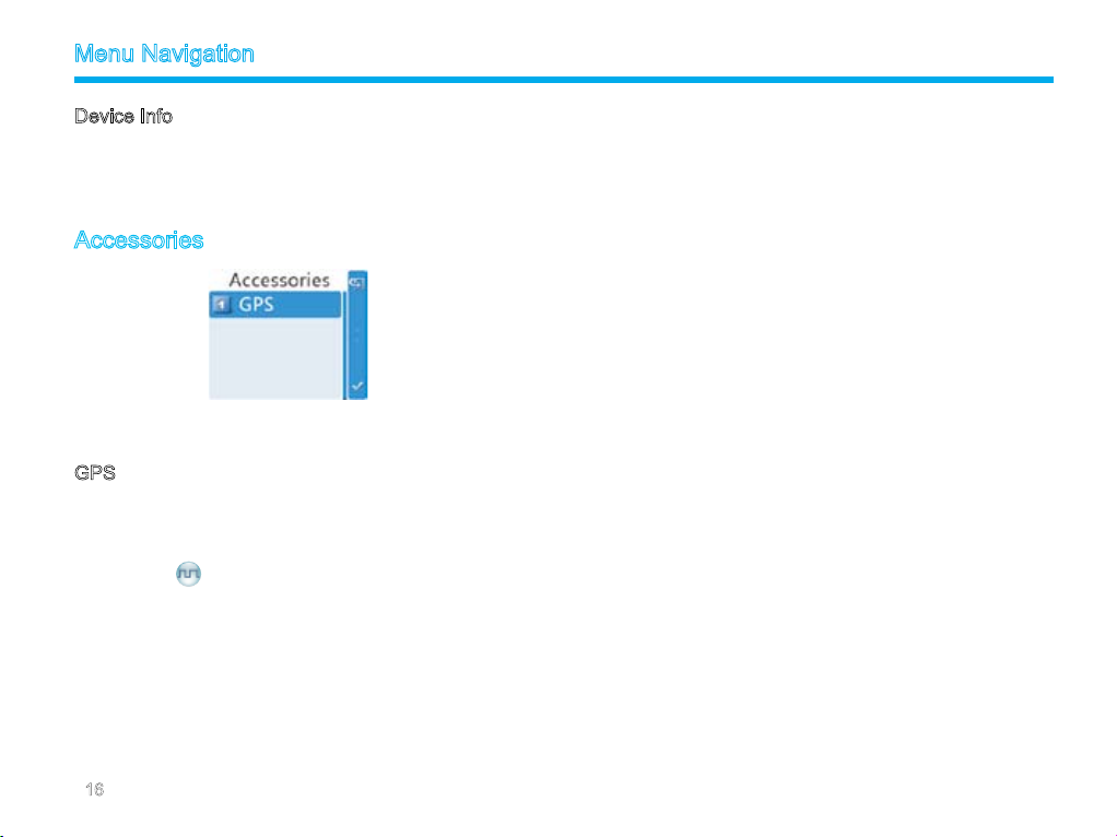
Accessories
To access this item, press the Menu key in the home screen and
then select “Accessories”.
GPS
Position
Wit h this option, you can vi ew longi tude, latit ude, ti me, date,
speed, altitude and SA (satellite) information of your radio.
GPS Text Msg
If the GPS feat ure is enabled via th e pr ogram ming softwar e,
you can sen d the GPS text message to your desired co ntact.
Operation:
1. Select “GPS Msg”, and press the OK key to access the menu
“Contact List”.
2. Use the Up/Down key to select a desired contact.
3. Press the OK key to send the GPS message to the selected
contact.
16
Time Zone
You can choose your time zone to correct the received GPS time.
We recommend you to set the time zone before your initial use of
this feature.
Page 22
Functions and Operations
Home Screen
The feature allows you to quickly return to the previous menu or
the home screen.
Operation:
In the editing screen, press the programmed Home Screen key,
and the radio exits the screen and returns to the previous menu
immediately; in other screens, press the key, and the radio returns
to the home screen immediately.
Scan
This feature allows you to listen to communication activities on
other channels so that you can keep a close track of your team
members.
Operation:
1. To enable the feature, you can select “On” from the menu
“Scan”; or
Press the programmed Scan key in the home screen; or
Switch t o a channel o n wh ic h the f eature “Aut o Sc an ” is
enabled via the programming software.
2. After the feature is enabled, your radio will scan according to
the scan list set for the channel on which scanning starts. The
scanning process is as follows:
During scanning, the LCD displays the icon , and the LED
ashes orange slowly.
When activities are detected on a channel, the radio will stay
on the channel to receive current activities. If your radio stays
on a non-priority channel, the LCD will display icon ; if on
Priority Channel 1 or Priority Channel 2, the LCD will display
icon or icon respectively.
If you don’t want to hear activities on the channel, press the
programmed Nuisance Temporary Delete key to remove the
channel from the scan list temporarily.
If you wa nt to c ont inu e st ayi ng on the cha nne l, press the
programmed Monitor or Squelch Off key during scan stay.
3. To exit the scanning process, you can select “Off” from the
menu “Scan”, or press the programmed Scan key again.
Public Address
This feature allows public address via the external speaker. After
the feature is enabled, your voice will not be transmitted, but out-
put via the external speaker (connected to the accessory jack on
the rear panel) if you hold down the PTT key and speak.
Operation:
1. Press the programmed Public Address key to enable the fea-
ture.
2. Hold down the PTT key and speak into the microphone. Then
your voice will be broadcasted clearly via the external speaker.
3. To disable the feature, press the Public Address key again.
Note: When this feature is enabled, you can neither
communicate with other users, nor enter the
menu.
17
Page 23
Functions and Operations
Talk Around
You can continue to communicate in DM mode by pressing the
programmed Talk Around key, when your repeater malfunctions,
or when your radio is out of the repeater’s range but within talking
range of other radios.
Operation:
Press the programmed Talk Around key to switch between DM
mode and RM mode.
Monitor
To adjust match conditions for signal receiving, you can enable the
feature “Monitor”.
Operation:
Press the programmed Monitor key to enable the feature, and
the radio displays icon . To disable the feature, press this
key again.
Hold down the programmed Monitor Momentary key to en-
able the feature, and the radio displays the icon . To disable
the feature, release this key.
Squelch Off
If the feature “Squelch Off ” is enabled , the speak er will keep
unmuted no matter whether carrier is present.
Operation:
Press the programmed Squelch Off key to enable the feature.
Then the radio displays the icon and sounds background
noise. To disable the feature, press this key again.
Hold down the programmed Squelch Off Momentary key to
enable the feature. Then the radio displays the icon and
sounds background noise. To disable the feature, release this
key.
Emergency
In case of an emergency, you can use the feature to ask for help
from your companion or control center. The Emergency process
has the highest priority. You can make emergency operation even
when your radio is transmitting or receiving.
To enable the feature on a channel, an emergency system must be
assigned to the channel via the programming software. In addition,
the Emergency type, Emergency ID type and Emergency mode
are settable via the programming software.
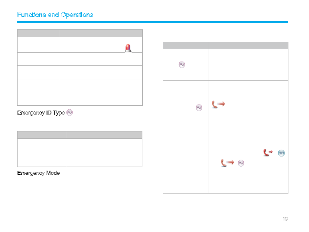
Emergency Type
For each Emer ge ncy mode, there are four Emergen cy type s
available. You can select one of them via your dealer:
18
Page 24
Functions and Operations
Emergency Type Description
Siren Only
Regular
Silent
Silent with Voice
In Emergency mode, the radio will sound
shrill alarm tone and display icon .
In Emergency mode, the radio will give
audible and visible indication.
In Emergency mode, the radio won't give
any audible or visible indication.
In Emergency mode, the radio won’t give
any audible or visible indication, but will
receive voice ACK from the companion
or control center automatically.
Emergency ID Type
Your radio supports two Emergency ID types. You can select one
of them via your dealer:
Emergency ID Type Description
None
HDC1200
No signaling is used when the radio
sends alarm information.
HDC1200 signaling is used when the
radio sends alarm information.
Emergency Mode
Your radio supports three Emergency modes. You can select one
of them via your dealer (Note: For the following operation methods,
we take the “Regular” type as an example).
Emergency Mode Description
In this mode, you can send alarm in-
formation to your companion or control
Alarm
Alarm with Call
Call Only
center by pres sing the programmed
Emergency key, but you cannot talk
with them.
In this mode, you can send alarm in-
formation by pressing the programmed
Emergen c y ke y. W h e n t he ic on
app ears, yo u can speak in to
the microphone, allowing your voice
and background noise to be transmit-
ted automatically (you do not need to
hold down the PTT key).
In this mode, press the programmed
Emer gency key to go to the Revert
Channel. When the icon
) or ( ) app ea rs, you can
speak into the microphone, allowing
your voice and background noise to be
transmitted automatically (you do not
need to hold down the PTT key).
(
19
Page 25
Functions and Operations
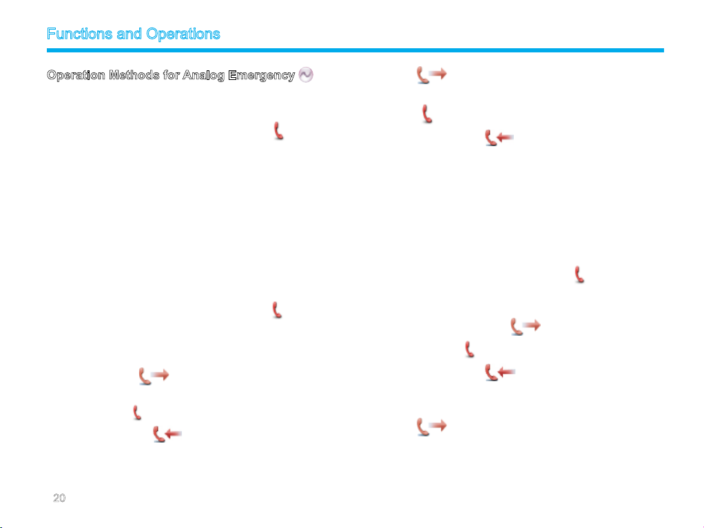
Operation Methods for Analog Emergency
Alarm (None & HDC1200)
Operation: P ress the programmed Emergency ke y to sen d
alarm informat io n. The radi o displa ys the i con an d te xt
information “Sending Alarm”, with red LED glowing. (None: If “Local
Emergency Alarm” is enabled via the programming software, an
alarm tone will sound.)
Two methods are available for you to exit the Emergency mode:
1. Onc e the emergenc y cycles expire, the radio will ex it the
Emergency mode automatically.
2. Long press the programmed Emergency key.
Alarm with Call (None & HDC1200)
Operation:
1. Pr e ss the prog ram m ed Eme rge n cy key to s end alar m
in f orm a tio n . T he r adi o disp l ays the ic on a nd tex t
information “Sending Alarm”, with red LED glowing. (None:
If “Local Emergency Alarm” is enabled via the programming
software, an alarm tone will sound.)
2. Wh en the icon
microphone to make an emergency call.
3. When the icon
is received, the icon
4. If the preset Voice Cycles expire, you can hold down the
key to make the emergency call again (the radio displays the
app ear s, you can spe ak int o t he
appears, you can receive. And when a call
appears.
PTT
icon , with red LED glowing). After the emergency call is
transmitted, release the PTT key to receive (the radio displays
icon , with LED ashing orange rapidly). And when a call
is received, the icon
Two methods are available for you to exit the Emergency mode:
1. After the preset Alarm Cycles and Voice Cycles expire, the
radio will exit the Emergency mode automatically. (None)
2. Long press the programmed Emergency key.
Call Only (HDC1200)
Operation:
1. Press the programmed Emergency key to go to the Revert
Channel, and the radio displays the icon .
2. If the feature “Alarm with Call to Follow” is enabled, you can
speak into the microphone to make an emergency call when
the radio displays the icon .
3. When the icon
is received, the icon
4. If the preset Voice Cycles expire, you can hold down the
key to make the emergency call again (the radio displays the
icon , with red LED glowing). After the emergency call is
transmitted, release the PTT key to receive (the radio displays
appears, you can receive. And when a call
appears. (HDC1200 only)
appears.
PTT
20
Page 26
Functions and Operations
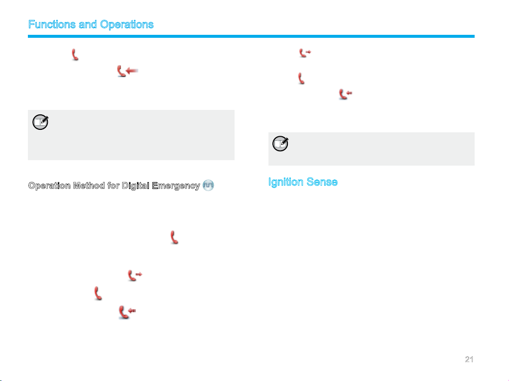
the icon , with LED ashing orange rapidly). And when a
call is received, the icon
To ex i t t he E me r gen cy mod e , l ong pres s the prog r am m ed
Emergency key.
Note: Your dealer may set the number of alarm
cycles and alarm duration (None), number of
polite retries and impolite retries (HDC1200),
number of voice cycles, duration of each
transmission and TX interval.
appears.
Operation Method for Digital Emergency
Call Only
Operation:
1. Press the programmed Emergency key to go to the Revert
Channel, and the radio displays the icon .
2. If the feature “Alarm with Call to Follow” is enabled, you can
speak into the microphone to make an emergency call when
the radio displays the icon .
3. When the icon
call is received, the icon appears.
4. If the preset Voice Cycles expire, you can hold down the
key to make the emergency call again (the radio displays the
appears, you can receive. And when a
PTT
icon , with red LED glowing). After the emergency call is
transmitted, release the PTT key to receive (the radio displays
icon , with LED ashing orange rapidly). And when a call is
received, the icon appears.
To ex it the Emerge ncy mode, long press the program med
Emergency key.
Note: Your dealer may set the number of voice
cycles, duration of each transmission and TX
interval.
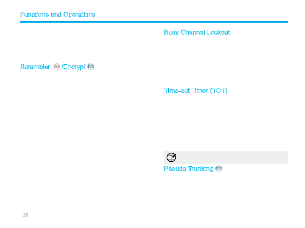
Ignition Sense
The following options are available via the vehicle ignition. You
may ask your dealer to assign any one to your radio.
PTT Disable: The PTT key is enabled or disabled by following
the ignition sense.
Operation:
To enable the PTT key, start the engine; to disable the PTT
key, stop the engine.
Ignition or Switch: The radio powers on or off by following
either the ignition sense or the Power On/Off key.
Operation:
To powe r on the ra dio , st art the engi ne or l ong pre ss the
Power On/Off key; to power it off, stop the engine or press the
Power On/Off key.
21
Page 27
Functions and Operations
Ignition Only
ignition sense only. The Power On/Off key does not work.
Operation:
To turn on the radio, start the engine; to turn it off, stop the
engine (The Power On/Off key does not work).
Scrambler
The Scrambler/Encrypt feature can encrypt your audio signals to
prevent eavesdropping. Thus privacy of your communication is
guaranteed.
This Encrypt feature can encrypt your audio signals and messages
to prevent eavesdropping. Thus privacy of your communication is
guaranteed.
Operation:
On an analog channel, go to “Main Menu -> Settings -> Radio
Set -> Scrambler” and select “Enable” or “Disable; on a digital
channel, go to “Main Menu -> Settings -> Radio Set -> En-
crypt” and select “Enable” or “Disable.
Press the progra mmed Scr ambler/Enc rypt key to enable
Scrambler or Encrypt on the current channel (a high-pitched
tone sounds); press the key again to disable the feature (a
low-pitched tone sounds).
If the Scrambler/Encrypt feature is enabled for a channel via
the programming software, switch to the channel to enable the
feature, or exit the channel to disable the feature.
: The radio powers on or off by following the
/Encrypt
Busy Channel Lockout
If enabled via the programming software, this feature can prevent
your radio interfering with other transmitting terminals on the same
channel. If you hold down the PTT key while the channel is in use,
your radio will keep beeping and display text information “Channel
Busy!”, alerting you to transmission prohibition. To stop beeping,
please release the PTT key. When the channel is free, you can
press and hold down the PTT key to transmit.
Time-out Timer (TOT)
The purpo se of TOT is to prevent any user fr om occupying a
channel for an extended period. If the preset time expires, the
radio will automatically terminate transmission and keep beeping.
To stop beeping, please release the PTT key. You must wait for
a certain time period (preset by your dealer) to initiate another
transmission.
If the pre-alert function is set by your dealer, your radio will alert
you to the TOT expiration in advance.
Note: This feature is null in Emergency mode.
Pseudo Trunking
If your radio operates on a channel with this feature enabled and
one time slot is already occupied, it can transmit and receive on
the other free time slot, allowing you to communicate timely under
emergent situations.
22
Page 28
Functions and Operations
MIC AGC
If enabled via the programming software, your radio will process
the audio signals during transmission, providing improved audio for
the receiving radio.
Emergency Footswitch
This feature must be realized through further development. After
successfully developed, you should request your dealer to enable it
via programming software. This feature is quite useful in emergent
situations to avoid any unexpected loss.
Note: Emergency footswitch will be unavailable if
the Emergency feature is not enabled on the
current channel.
Channel Steering
This feature must be realized through further development. After
successfully developed, you should request your dealer to enable
it via programming software. You can switch channels accurately
and quickly with this feature.
Note: If this feature is enabled, you cannot switch
channels via front panel operation.
23
Page 29
Signaling Introduction
The radio supports the following signaling. You can ask your dealer
to make appropriate settings on your radio. For detailed informa-
tion, please contact your dealer.
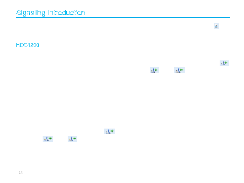
HDC1200
The HDC1200 signaling is compatible with the MDC1200 signaling,
and realizes functions such as PTT ID (Encoding & Decoding),
Emergency (Encoding & Decoding) and Selective Call (Encoding
& Decoding).
Encoding:
1. Hold down the PTT key during normal voice communication to
send PTT ID.
2. Go to the menu “Contact List” and select a required contact.
Then hold down the PTT key to send a selective call (Private
Call/Group Call/All Call).
For encoding, the radio will provide the following indications:
PTT ID/Selective Call: Your dealer can program whether the
radio sounds side tone during encoding or sounds beeps after
encoding.
Selective Call: During encoding, the LED glows red, and the
LCD displays the appropriate call icon (Private Call:
; Group Call: ; All Call: ).After encoding, the LED
glows orange.
Decoding:
For decoding, the radio provides the following indications:
PTT ID: After decoding, the LCD displays the icon and ID
or alias of the transmitting party.
Selective Call: After decoding, the radio provides the following
indications:
Alert:The radio will sound default alert.
LED:The LED glows green.
LCD:If your dealer enables the feature “Display Decode ID”, the
radio will display the appropriate call icon (Private Call: ;
Group Call: ; All Call: ) and alias of the transmitting
party (ID of the transmitting party will be displayed if it is not in the
contact list). If your dealer does not enable the feature “Display
Decode ID”, the radio will display the appropriate call icon only.
24
Page 30
Troubleshooting
Phenomena Analysis Solution
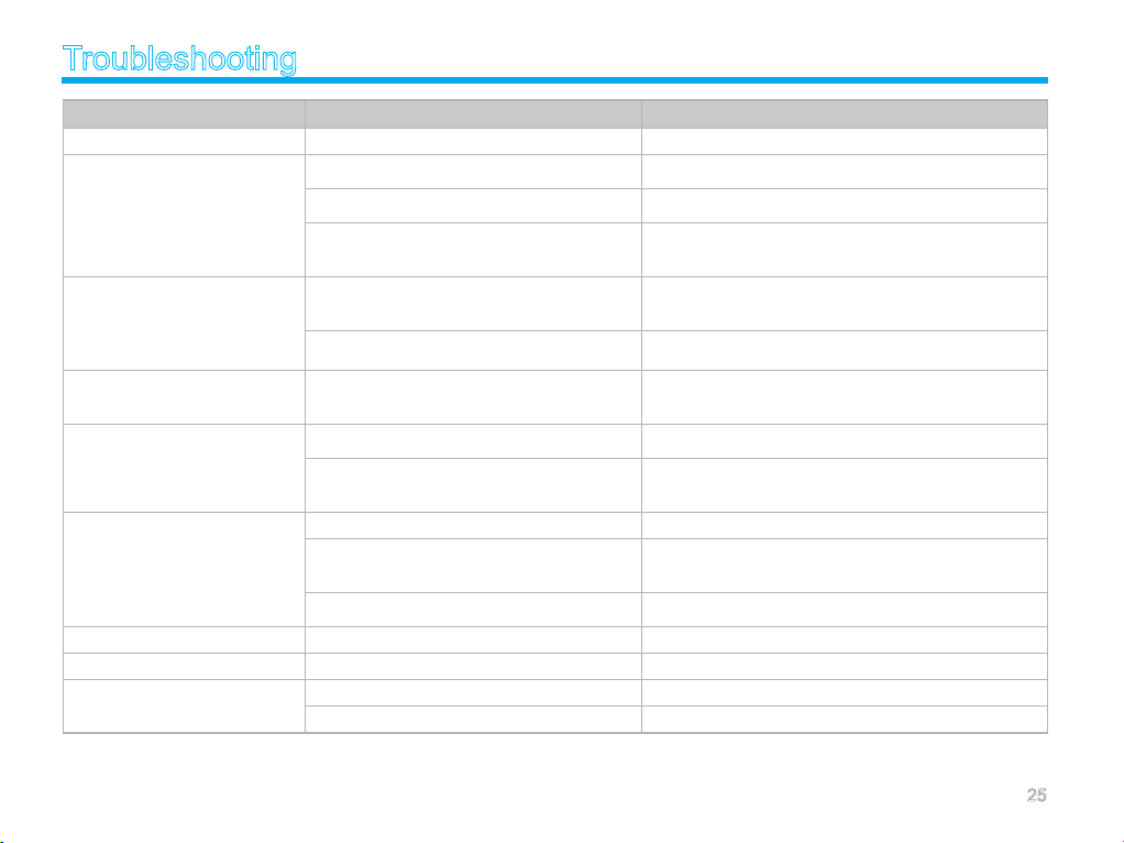
The radio can not be powered on. The power cord may be unconnected. Connect the power cord correctly.
The volume may be set to a low level.
During receiving signals, the voice is
weak, discontinuous or totally inac-
tive.
You can not communicate with other
members in Analog mode.
You can not communicate with other
memb ers in Digi tal mode alt houg h
there is receiving indication.
Irrelevant communications or noises
are heard on the analog channel.
The noise is too loud.
You can not use the keys. The keypad may fail to function temporarily. Restart the radio.
There is no display. The LCD may fail to function temporarily. Restart the radio.
The GPS cannot locate your position.
The antenna may get loose or ma y be improper ly
installed.
The speaker may be blocked or damaged.
The frequency or signaling may be inconsistent with
that of other members.
You may be too far away from the group members.
Your ID may be inconsistent with that of other mem-
bers. Consequently, the digital carrier can be received
but can not be demodulated.
You m ay be in terrupted by radi os using the same
frequency.
The radio may be set with no signaling.
You may be too far away from other members. Move towards other members, and then try again.
You may be at an unfavorable position. For example,
your communicati on may be blocked by high build-
ings or frustrated in the underground areas.
You may suffer from external disturbance (such a s
electromagnetic interference).
The GPS antenna is improperly connected. Connect the GPS antenna correctly.
No GPS signal is received. Move to an open and at area, and restart the radio.
If the above solutions can not x your problems, or you may have some other queries, please contact us or your local dealer for more technical
support.
Increase the volume by rotating the Volume Control knob clock-
wise.
Power off the radio, re-install the antenna and power on the radio
again.
Clean surface of the speaker. If the problem can not be solved,
contact your dealer or our authorized service center for inspec-
tion and repair.
Set your TX/RX frequency and signaling to the same as that of
other members.
Move towards other members. And make sure that you are within
the communication range.
Set your ID to the same as that of other members.
Adjust the squelch level.
Set your radio with signaling to avoid interference at the same
frequency, and make sure that all members share the same sig-
naling.
Move to an open and at area, and try again.
Stay away from equipment that may cause interference.
25
Page 31
Care and Cleaning
To guarantee optimal performance as well as a long service life of
the product, please follow the tips below.
Product Care
Keep the product at a place with good ventilation and heat
dissipation to facilitate normal work.
Do not place irrelevant articles on top of the product to ensure
optimal heat dissipation.
Do no t place the prod uct in corr osive agents, soluti ons or
water.
Product Cleaning
Clean up the dust and ne particles on the product parts with a
clean and dry lint-free cloth or a brush regularly.
Use a non-woven fabric with neutral cleanser to clean the
keys, control knobs, LCD and jacks after long-time use. Do not
use chemical preparations such as stain removers, alcohol,
sprays or oil preparations. Make sure the product is completely
dry before use.
Caution: Power off the product before cleaning.
26
Page 32
Optional Accessories
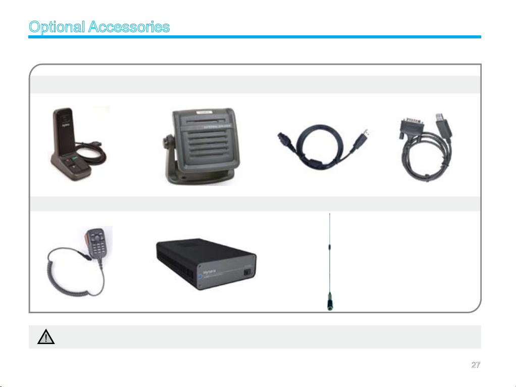
The following items are the main optional accessories for the product, and please consult your local dealer for more information.
Desktop Microphone SM10A1 External Speaker SM09D1 Programming Cable (USB Port) PC37 Data Cable PC40
Keypad Microphone SM19A1 320W External Power Supply PS22002 Antenna
Caution: Use the accessories specied by Hytera only. If not, Hytera shall not be liable for any losses or damages arising out of use
of unauthorized accessories.
27
Page 33
Appendix
Input Method
You ca n en t e r al i a s es, nu mber s or me s sage s usin g the
microphone with a keypad. The radio supports the following input
methods: Chinese Pinyin (simplied), English and Number.
Chinese Pinyin (Simplied)
Operation:
1. Press to switch to Chinese Pinyin mode;
2. Enter the pin yin through alphanumeric keys; then a list of
pos sible combi natio ns and co rresp ondin g char acter s wi ll
appear;
3. Use the Up/Down key to choose the right pinyin;
4. Press the OK key to highlight the characters, and choose the
right character using the Up/Down key;
5. Press the OK key to enter the selected character.
You can repeat the above steps to continue.
English
Operation:
1. Press to swit ch to up percase En gl ish or lowercas e
English mode;
2. Enter the English letters through alphanumeric keys;
3. Use the Up/Down key to choose the right letter;
4. Press the OK key to enter the selected letter.
You can repeat the above steps to continue.
Number
Operation:
1. Press to switch to Number mode;
2. Enter the numbers through alphanumeric keys to .
Special Character
To enter common punctuations and special characters, press .
To input a space, press
Note: You can use the Up/Down key to move the
cursor leftward/rightward in the entered text.
.
28
 Loading...