

Page 1
1
5
2
5
ft
4
.5
-7
.5
m
35
-5
0 ft
1
2
1
5
m
6.0
BAR
5.0
4.0
PSI
80
70
50
60
8
0
A
M
P
S
120926 120925
120978
120927120928
120928
120929
120977
110378 Rev. A
6.0
BAR
5.
0
4.
0
PSI
80
705060
60
40
AMPS
80
25
AC
+
_
15-5
0 ft
4.5-15 m
15-25 ft
4.5-7.5 m
35-50 ft
12-15 m
6.0
B
A
R
5
.
0
4
.
0
P
S
I
80
70
50
60
8
0
A
M
P
S
8
0
A
M
P
S
Plasma Arc
Cutting System
Operator Manual
803950 Revision 1
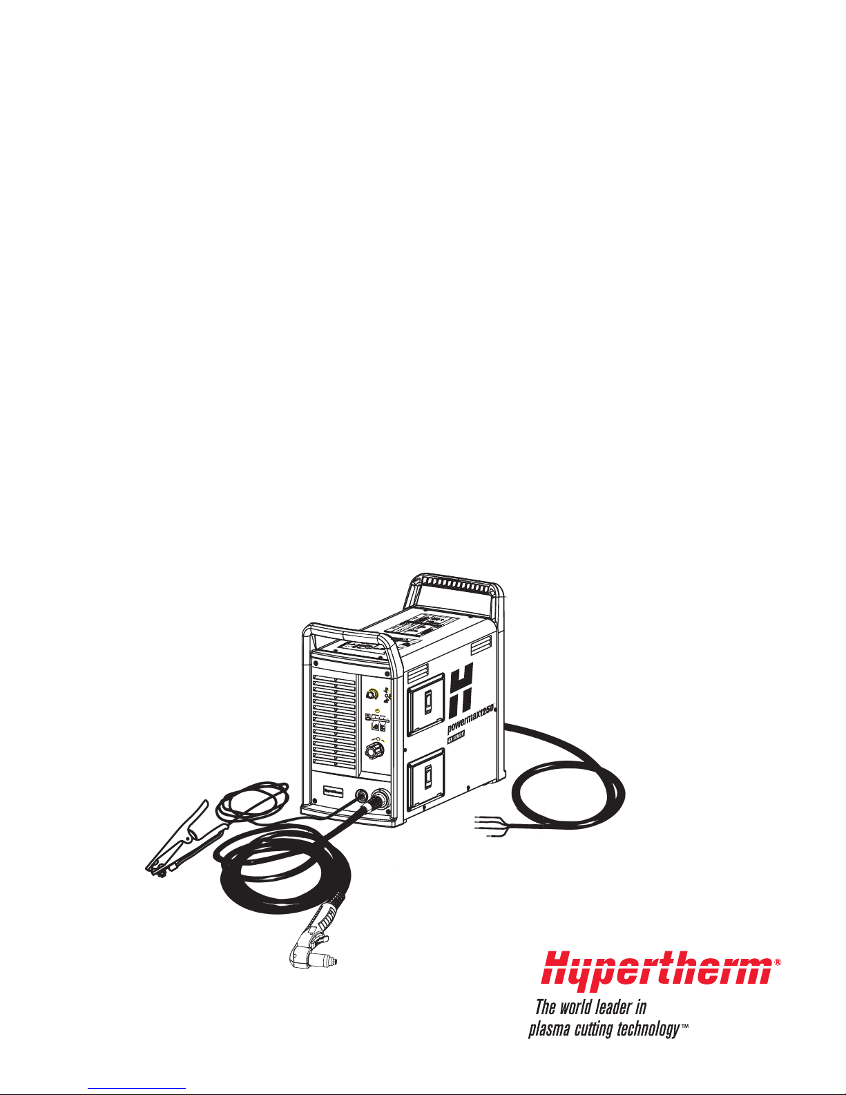
powermax1250
®
Page 2

Operator Manual
(P/N 803950)
Revision 1 – April 2007
Hypertherm, Inc.
Hanover, NH USA
www.hypertherm.com
© Copyright 2007 Hypertherm, Inc.
All Rights Reserved
Hypertherm, Powermax, and FineCut are trademarks of Hypertherm, Inc.
and may be registered in the United States and/or other countries.
powermax1250
Page 3

1/19/07
Hypertherm, Inc.
Etna Road, P.O. Box 5010
Hanover, NH 03755 USA
603-643-3441 Tel (Main Office)
603-643-5352 Fax (All Departments)
[email protected] (Main Office Email)
800-643-9878 Tel (Technical Service)
[email protected] (Technical Service Email)
800-737-2978 Tel (Customer Service)
[email protected] (Customer Service Email)
Hypertherm Automation
5 Technology Drive, Suite 300
West Lebanon, NH 03784 USA
603-298-7970 Tel
603-298-7977 Fax
Hypertherm Plasmatechnik GmbH
Technologiepark Hanau
Rodenbacher Chaussee 6
D-63457 Hanau-Wolfgang, Deutschland
49 6181 58 2100 Tel
49 6181 58 2134 Fax
49 6181 58 2123 (Technical Service)
Hypertherm (S) Pte Ltd.
No. 19 Kaki Bukit Road 2
K.B. Warehouse Complex
Singapore 417847, Republic of Singapore
65 6 841 2489 Tel
65 6 841 2490 Fax
65 6 841 2489 (Technical Service)
Hypertherm (Shanghai) Trading Co., Ltd.
Unit 1308-09, Careri Building
432 West Huai Hai Road
Shanghai, 200052
PR China
86-21 5258 3330/1 Tel
86-21 5258 3332 Fax
Hypertherm
Branch of Hypertherm, UK, UC
PO Box 244
Wigan, Lancashire, England WN8 7WU
00 800 3324 9737 Tel
00 800 4973 7329 Fax
00 800 4973 7843 (Technical Service)
France (Representative office)
15 Impasse des Rosiers
95610 Eragny, France
00 800 3324 9737 Tel
00 800 4973 7329 Fax
Hypertherm S.r.l.
Via Torino 2
20123 Milano, Italia
39 02 725 46 312 Tel
39 02 725 46 400 Fax
39 02 725 46 314 (Technical Service)
Hypertherm Europe B.V.
Vaartveld 9
4704 SE Roosendaal, Nederland
31 165 596907 Tel
31 165 596901 Fax
31 165 596908 Tel (Marketing)
31 165 596900 Tel (Technical Service
)
00 800 49 73 7843 Tel (Technical Ser
v
Hypertherm Japan Ltd.
801 Samty Will Building
2-40 Miyahara 1-Chome,
Yodogawa-ku, Osaka
532-0003, Japan
81 6 6170 2020 Tel
81 6 6170 2015 Fax
HYPERTHERM BRASIL LTDA.
Avenida Doutor Renato de
Andrade Maia 350
Parque Renato Maia
CEP 07114-000
Guarulhos, SP Brasil
55 11 6409 2636 Tel
55 11 6408 0462 Fax
Page 4

ELECTROMAGNETIC COMPATIBILITY (EMC)
8-06
Hypertherm Plasma Systems i
EMC Introduction
Hypertherm’s CE-marked equipment is built in
compliance with standard EN60974-10. The
equipment should be installed and used in
accordance with the information below to achieve
electromagnetic compatibility.
The limits required by EN60974-10 may not be
adequate to completely eliminate interference
when the affected equipment is in close proximity
or has a high degree of sensitivity. In such cases
it may be necessary to use other measures to
further reduce interference.
This plasma equipment is designed for use only in
an industrial environment.
Installation and use
The user is responsible for installing and using
the plasma equipment according to the
manufacturer’s instructions. If electromagnetic
disturbances are detected then it shall be the
responsibility of the user to resolve the situation
with the technical assistance of the manufacturer.
In some cases this remedial action may be as
simple as earthing the cutting circuit, see
Earthing of Workpiece.
In other cases it could
involve constructing an electromagnetic screen
enclosing the power source and the work
complete with associated input filters. In all cases
electromagnetic disturbances must be reduced to
the point where they are no longer troublesome.
Assessment of area
Before installing the equipment the user shall
make an assessment of potential electromagnetic
problems in the surrounding area. The following
shall be taken into account:
a. Other supply cables, control cables, signalling
and telephone cables; above, below and
adjacent to the cutting equipment.
b. Radio and television transmitters and
receivers.
c. Computer and other control equipment.
d. Safety critical equipment, for example guarding
of industrial equipment.
e. Health of the people around, for example the
use of pacemakers and hearing aids.
f. Equipment used for calibration or
measurement.
g. Immunity of other equipment in the
environment. User shall ensure that other
equipment being used in the environment is
compatible. This may require additional
protection measures.
h. Time of day that cutting or other activities are
to be carried out.
The size of the surrounding area to be considered
will depend on the structure of the building and
other activities that are taking place. The
surrounding area may extend beyond the boundaries of the premises.
Methods of reducing emissions
Mains supply
Cutting equipment must be connected to the
mains supply according to the manufacturer’s
recommendations. If interference occurs, it may
be necessary to take additional precautions such
as filtering of the mains supply. Consideration
should be given to shielding the supply cable of
permanently installed cutting equipment, in
metallic conduit or equivalent. Shielding should
be electrically continuous throughout its length.
The shielding should be connected to the cutting
mains supply so that good electrical contact is
maintained between the conduit and the cutting
power source enclosure.
Maintenance of cutting equipment
The cutting equipment must be routinely
maintained according to the manufacturer’s
recommendations. All access and service doors
and covers should be closed and properly
fastened when the cutting equipment is in
operation. The cutting equipment should not be
modified in any way except for those changes and
adjustments covered in the manufacturer’s
Page 5

ELECTROMAGNETIC COMPATIBILITY (EMC)
8-06
ii Hypertherm Plasma Systems
instructions. In particular, the spark gaps of arc
striking and stabilizing devices should be adjusted
and maintained according to the manufacturer’s
recommendations.
Cutting cables
The cutting cables should be kept as short as
possible and should be positioned close together,
running at or close to the floor level.
Equipotential bonding
Bonding of all metallic components in the cutting
installation and adjacent to it should be
considered. However, metallic components
bonded to the workpiece will increase the risk that
the operator could receive a shock by touching
these metallic components and the electrode at
the same time. The operator should be insulated
from all such bonded metallic components.
Earthing of workpiece
Where the workpiece is not bonded to earth for
electrical safety, nor connected to earth because
of its size and position, for example, ship’s hull or
building steelwork, a connection bonding the
workpiece to earth may reduce emissions in
some, but not all instances. Care should be
taken to prevent the earthing of the workpiece
increasing the risk of injury to users, or damage to
other electrical equipment. Where necessary, the
connection of the workpiece to earth should be
made by a direct connection to the workpiece, but
in some countries where direct connection is not
permitted, the bonding should be achieved by
suitable capacitances selected according to
national regulations.
Note: the cutting circuit may or may not be
earthed for safety reasons. Changing the earthing
arrangements should only be authorized by a
person who is competent to assess whether the
changes will increase the risk of injury, for
example, by allowing parallel cutting current return
paths which may damage the earth circuits of
other equipment. Further guidance is given in
IEC/ TS 62081 Arc Welding Equipment Installation
and Use.
Screening and shielding
Selective screening and shielding of other cables
and equipment in the surrounding area may
alleviate problems of interference. Screening of
the entire plasma cutting installation may be considered for special applications.
Page 6

WARRANTY
Hypertherm Plasma Systems iii
8-06
Warning
Genuine Hypertherm parts are the factoryrecommended replacement parts for your
Hypertherm system. Any damage caused by the
use of other than genuine Hypertherm parts may
not be covered by the Hypertherm warranty.
Warning
You are responsible for the safe use of the
Product. Hypertherm does not and cannot make
any guarantee or warranty regarding the safe use
of the Product in your environment.
General
Hypertherm, Inc. warrants that its Products shall
be free from defects in materials and
workmanship, if Hypertherm is notified of a defect
(i) with respect to the power supply within a period
of two (2) years from the date of its delivery to
you, with the exception of Powermax Series
power supplies, which shall be within a period of
three (3) years from the date of delivery to you,
and (ii) with respect to the torch and leads within a
period of one (1) year from its date of delivery to
you. This warranty shall not apply to any Product
which has been incorrectly installed, modified, or
otherwise damaged. Hypertherm, at its sole
option, shall repair, replace, or adjust, free of
charge, any defective Products covered by
this warranty which shall be returned with
Hypertherm’s prior authorization (which shall not
be unreasonably withheld), properly packed, to
Hypertherm’s place of business in Hanover,
New Hampshire, or to an authorized Hypertherm
repair facility, all costs, insurance and freight
prepaid. Hypertherm shall not be liable for any
repairs, replacement, or adjustments of Products
covered by this warranty, except those made
pursuant to this paragraph or with Hypertherm’s
prior written consent. The warranty above is
exclusive and is in lieu of all other warranties,
express, implied, statutory, or otherwise with
respect to the Products or as to the results
which may be obtained therefrom, and all
implied warranties or conditions of quality or
of merchantability or fitness for a particular
purpose or against infringement. The
foregoing shall constitute the sole and
exclusive remedy for any breach by
Hypertherm of its warranty. Distributors/OEMs
may offer different or additional warranties, but
Distributors/OEMs are not authorized to give any
additional warranty protection to you or make any
representation to you purporting to be binding
upon Hypertherm.
Certification test marks
Certified products are identified by one or more
certification test marks from accredited testing
laboratories. The certification test marks are
located on or near the data plate. Each certification
test mark means that the product and its safetycritical components conform to the relevant national
safety standards as reviewed by that testing
laboratory. Hypertherm places a certification test
mark on its products only after that product is
manufactured with safety-critical components that
have been authorized by the accredited testing
laboratory.
Once the product has left the Hypertherm factory,
the certification test marks are invalidated if any of
the following occurs:
• The product is significantly modified in a manner
that creates a hazard or non-conformance.
• Safety-critical components are replaced with
unauthorized spare parts.
• Any unauthorized assembly or accessory that
uses or generates a hazardous voltage is added.
• There is any tampering with a safety circuit or
other feature that is designed into the product as
part of the certification.
CE marking constitutes a manufacturer’s
declaration of conformity to applicable European
directives and standards. Only those versions of
Hypertherm products with a CE Marking located on
or near the data plate have been tested for
compliance with the European Low Voltage
Directive and the European EMC Directive.
Page 7

WARRANTY
8-06
iv Hypertherm Plasma Systems
EMC filters needed to comply with the European
EMC Directive are incorporated within versions of
the power supply with a CE Marking.
Patent indemnity
Except only in cases of products not
manufactured by Hypertherm or manufactured by
a person other than Hypertherm not in strict
conformity with Hypertherm’s specifications and in
cases of designs, processes, formulae, or
combinations not developed or purported to be
developed by Hypertherm, Hypertherm will
defend or settle, at its own expense, any suit or
proceeding brought against you alleging that the
use of the Hypertherm product, alone and not in
combination with any other product not supplied
by Hypertherm, infringes any patent of any third
party. You shall notify Hypertherm promptly upon
learning of any action or threatened action in
connection with any such alleged infringement,
and Hypertherm’s obligation to indemnify shall be
conditioned upon Hypertherm’s sole control of,
and the indemnified party’s cooperation and
assistance in, the defense of the claim.
Limitation of liability
In no event shall Hypertherm be liable to any
person or entity for any incidental,
consequential, indirect, or punitive damages
(including but not limited to lost profits)
regardless of whether such liability is based
on breach of contract, tort, strict liability,
breach of warranties, failure of essential
purpose or otherwise and even if advised of
the possibility of such damages.
Liability cap
In no event shall Hypertherm’s liability,
whether such liability is based on breach of
contract, tort, strict liability, breach of
warranties, failure of essential purpose or
otherwise, for any claim action suit or
proceeding arising out of or relating to the use
of the Products exceed in the aggregate the
amount paid for the Products that gave rise to
such claim.
Insurance
At all times you will have and maintain insurance
in such quantities and types, and with coverage
sufficient and appropriate to defend and to hold
Hypertherm harmless in the event of any cause of
action arising from the use of the Products.
National and Local codes
National and Local codes governing plumbing and
electrical installation shall take precedent over any
instructions contained in this manual. In no event
shall Hypertherm be liable for injury to persons or
property damage by reason of any code violation
or poor work practices.
Transfer of rights
You may transfer any remaining rights you may
have hereunder only in connection with the sale of
all or substantially all of your assets or capital
stock to a successor in interest who agrees to be
bound by all of the terms and conditions of this
Warranty.
Proper disposal of Hypertherm
products
Hypertherm plasma cutting systems, like all
electronic products, may contain materials or
components, such as printed circuit boards, that
cannot be discarded with ordinary waste. It is your
responsibility to dispose of any Hypertherm product
or component part in an environmentally
acceptable manner according to national and local
codes.
• In the United States, check all federal, state, and
local laws.
• In the European Union, check the EU directives,
national, and local laws.
• In other countries, check national and local laws.
Register your product on-line at:
www.hypertherm.com/warranty.htm
Page 8

TABLE OF CONTENTS
1
powermax1250 Operator Manual v
Electromagnetic Compatibility ......................................................................................................i
Warranty......................................................................................................................................iii
Section 1 Safety
Recognize safety information...................................................................................................1-2
Follow safety instructions .........................................................................................................1-2
Cutting can cause fire or explosion ..........................................................................................1-2
Electric shock can kill ...............................................................................................................1-3
Static electricity can damage circuit boards .............................................................................1-3
Toxic fumes can cause injury or death .....................................................................................1-4
A plasma arc can cause injury and burns.................................................................................1-5
Arc rays can burn eyes and skin ..............................................................................................1-5
Grounding safety......................................................................................................................1-6
Compressed gas equipment safety..........................................................................................1-6
Gas cylinders can explode if damaged ....................................................................................1-6
Noise can damage hearing ......................................................................................................1-7
Pacemaker and hearing aid operation .....................................................................................1-7
A plasma arc can damage frozen pipes...................................................................................1-7
Additional safety information ....................................................................................................1-7
Warning label............................................................................................................................1-8
Section 1a Sécurité
Identifier les consignes de sécurité ........................................................................................1a-2
Suivre les instructions de sécurité..........................................................................................1a-2
Danger Avertissement Précaution........................................................................................1a-2
Le coupage peut provoquer un incendie ou une explosion....................................................1a-2
Les chocs électriques peuvent être fatals ..............................................................................1a-3
L’électricité statique peut endommager les cartes de circuits imprimés.................................1a-3
Le vapeurs toxiques peuvent provoquer des blessures ou la mort........................................1a-4
L’arc plasma peut provoquer des blessures ou des brûlures.................................................1a-5
Les rayons de l’arc peuvent brûler les yeux et la peau ..........................................................1a-5
Mise à la masse et à la terre ..................................................................................................1a-6
Sécurité des bouteilles de gaz comprimé...............................................................................1a-6
Les bouteilles de gaz comprimé peuvent exploser en cas de dommages.............................1a-6
Le bruit peut provoquer des problèmes auditifs .....................................................................1a-7
Pacemakers et prothèses auditives .......................................................................................1a-7
Un arc plasma peut endommager les tuyaux gelés ...............................................................1a-7
Étiquette de sécurité...............................................................................................................1a-8
Section 1b Seguridad
Reconocimiento de información de seguridad .......................................................................1b-2
Siga las instrucciones de seguridad.......................................................................................1b-2
Los cortes pueden provocar incendios o explosiones............................................................1b-2
El choque eléctrico puede provocar la muerte.......................................................................1b-3
Electricidad estática puede dañar tablillas de circuito............................................................1b-3
Humos tóxicos pueden causar lesiones o muerte..................................................................1b-4
El arco de plasma puede causar lesiones y quemaduras......................................................1b-5
Los rayos del arco pueden producir quemaduras en los ojos y en la piel..............................1b-5
Page 9

TABLE OF CONTENTS
1
vi powermax1250 Operator Manual
Seguridad de toma a tierra.....................................................................................................1b-6
Seguridad de los equipos de gas comprimido .......................................................................1b-6
Los cilindros de gas pueden explotar si están dañados.........................................................1b-6
El ruido puede deteriorar la audición......................................................................................1b-7
Operación de marcapasos y de audífonos.............................................................................1b-7
Un arco plasma puede dañar tubos congelados....................................................................1b-7
Etiquetas de advertencia........................................................................................................1b-8
Section 2 Specifications
Power supply ...........................................................................................................................2-2
Dimensions and weight....................................................................................................2-3
T80 Torches .............................................................................................................................2-4
Dimensions......................................................................................................................2-5
Symbols and markings.............................................................................................................2-6
S mark ............................................................................................................................2-6
CE mark...........................................................................................................................2-6
IEC symbols used............................................................................................................2-6
Section 3 Setup
Upon receipt.............................................................................................................................3-2
Claims ......................................................................................................................................3-2
Contents of box ........................................................................................................................3-2
Locating the power supply........................................................................................................3-3
Lifting the power supply............................................................................................................3-3
Power connection.....................................................................................................................3-4
Three-phase power cord – plug installation .............................................................................3-4
Single-phase power cord..........................................................................................................3-5
Power cord installation.....................................................................................................3-5
Plug installation................................................................................................................3-5
Grounding ................................................................................................................................3-6
Extension cords........................................................................................................................3-6
Torch installation.......................................................................................................................3-7
Plasma gas supply ..................................................................................................................3-9
Additional gas filtration.....................................................................................................3-9
Gas supply installation ...........................................................................................................3-10
T80M torch alignment.............................................................................................................3-10
ON/OFF pendant connection.........................................................................................3-11
Machine interface connection ........................................................................................3-11
Arc voltage.....................................................................................................................3-12
Changing XFER (start machine motion) from dry contact closure to voltage signal......3-14
Driving an industrial isolated input module....................................................................3-15
Driving a relay coil with an external power source........................................................3-16
Driving an industrial isolated input module with an external power source ...................3-17
Page 10

TABLE OF CONTENTS
1
powermax1250 Operator Manual vii
Section 4 Operation
Controls and indicators.............................................................................................................4-2
Indicator LEDs.................................................................................................................4-2
T80 consumable configurations ...............................................................................................4-3
Shielded...........................................................................................................................4-3
FineCut............................................................................................................................4-3
Gouging...........................................................................................................................4-4
T80M consumable configurations ............................................................................................4-4
Shielded...........................................................................................................................4-4
FineCut............................................................................................................................4-5
Ohmic sensing retaining cap ...........................................................................................4-5
Unshielded.......................................................................................................................4-5
Install the torch consumables...................................................................................................4-7
Set the mode switch.................................................................................................................4-8
Set the power switch to ON......................................................................................................4-8
Check the indicator lights .........................................................................................................4-8
Adjust the gas pressure and current setting.............................................................................4-9
Hand torch operation..............................................................................................................4-10
Safety trigger operation .................................................................................................4-10
Attach the work clamp....................................................................................................4-11
Starting a cut from the edge of the workpiece ...............................................................4-11
Hand torch cutting technique.........................................................................................4-12
Piercing..........................................................................................................................4-13
Gouging.........................................................................................................................4-14
Cut charts...............................................................................................................................4-15
80 amp mechanized shielded consumables..................................................................4-15
60 amp mechanized shielded consumables..................................................................4-16
40 amp mechanized shielded consumables..................................................................4-17
FineCut consumables....................................................................................................4-18
40 amp mechanized unshielded consumables..............................................................4-19
Section 5 Maintenance and Parts
Routine maintenance ...............................................................................................................5-2
Inspect the consumables..........................................................................................................5-3
Controls and indicators.............................................................................................................5-4
Indicator LEDs.................................................................................................................5-4
Basic troubleshooting...............................................................................................................5-5
System circuit diagram.............................................................................................................5-8
Technical questions..................................................................................................................5-9
Parts.........................................................................................................................................5-9
Torch parts.......................................................................................................................5-9
Power supply parts........................................................................................................5-10
Accessories ...................................................................................................................5-10
Page 11

TABLE OF CONTENTS
0
viii powermax1250 Operator Manual
Page 12

Hypertherm Plasma Systems 1-1
8-06
Section 1
SAFETY
In this section:
Recognize safety information...................................................................................................1-2
Follow safety instructions .........................................................................................................1-2
Cutting can cause fire or explosion ..........................................................................................1-2
Electric shock can kill ...............................................................................................................1-3
Static electricity can damage circuit boards .............................................................................1-3
Toxic fumes can cause injury or death .....................................................................................1-4
A plasma arc can cause injury and burns.................................................................................1-5
Arc rays can burn eyes and skin ..............................................................................................1-5
Grounding safety......................................................................................................................1-6
Compressed gas equipment safety..........................................................................................1-6
Gas cylinders can explode if damaged ....................................................................................1-6
Noise can damage hearing ......................................................................................................1-7
Pacemaker and hearing aid operation .....................................................................................1-7
A plasma arc can damage frozen pipes...................................................................................1-7
Additional safety information ....................................................................................................1-7
Warning labels..........................................................................................................................1-8
Page 13
1-2 Hypertherm Plasma Systems
11-98
SAFETY
RECOGNIZE SAFETY INFORMATION
The symbols shown in this section are
used to identify potential hazards. When you see a
safety symbol in this manual or on your machine,
understand the potential for personal injury, and
follow the related instructions to avoid the hazard.
FOLLOW SAFETY INSTRUCTIONS
Read carefully all safety messages in
this manual and safety labels on your
machine.
• Keep the safety labels on your machine in good
condition. Replace missing or damaged labels
immediately.
• Learn how to operate the machine and how to
use the controls properly. Do not let anyone
operate it without instruction.
• Keep your machine in proper working condition.
Unauthorized modifications to the machine may
affect safety and machine service life.
DANGER WARNING CAUTION
A signal word DANGER or WARNING is used with
a safety symbol. DANGER identifies the most
serious hazards.
• DANGER and WARNING safety labels are
located on your machine near specific hazards.
• WARNING safety messages precede related
instructions in this manual that may result in
injury or death if not followed correctly.
• CAUTION safety messages precede related
instructions in this manual that may result in
damage to equipment if not followed correctly.
Fire Prevention
• Be sure the area is safe before doing any
cutting. Keep a fire extinguisher nearby.
• Remove all flammables within 35 feet (10 m) of
the cutting area.
• Quench hot metal or allow it to cool before
handling or before letting it touch combustible
materials.
• Never cut containers with potentially flammable
materials inside – they must be emptied and
properly cleaned first.
• Ventilate potentially flammable atmospheres
before cutting.
• When cutting with oxygen as the plasma gas, an
exhaust ventilation system is required.
Explosion Prevention
• Do not use the plasma system if explosive dust
or vapors may be present.
• Do not cut pressurized cylinders, pipes, or any
closed container.
• Do not cut containers that have held combustible
materials.
CUTTING CAN CAUSE FIRE OR EXPLOSION
WARNING
Explosion Hazard
Argon-Hydrogen and Methane
Hydrogen and methane are flammable gases that
present an explosion hazard. Keep flames away
from cylinders and hoses that contain methane or
hydrogen mixtures. Keep flames and sparks away
from the torch when using methane or argonhydrogen plasma.
WARNING
Hydrogen Detonation with
Aluminum Cutting
• When cutting aluminum underwater, or with the
water touching the underside of the aluminum,
free hydrogen gas may collect under the
workpiece and detonate during plasma cutting
operations.
• Install an aeration manifold on the floor of the
water table to eliminate the possibility of hydrogen
detonation. Refer to the Appendix section of this
manual for aeration manifold details.
Page 14
Hypertherm Plasma Systems 1-3
8-06
SAFETY
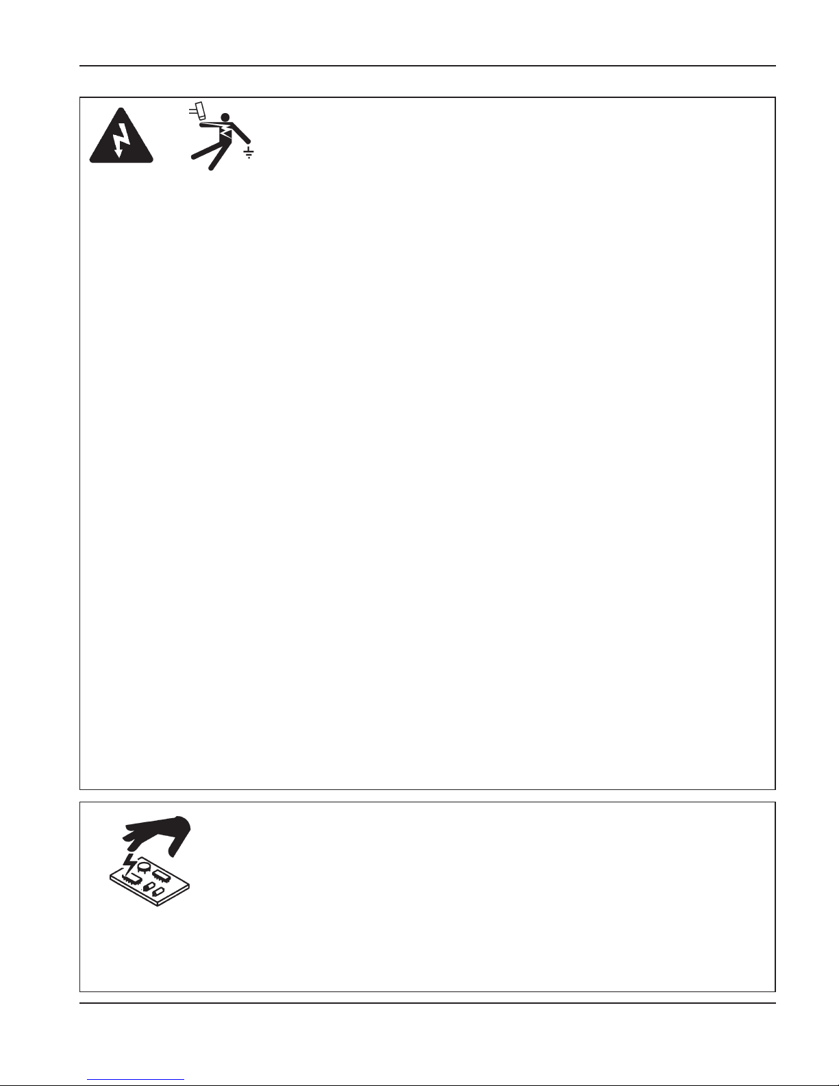
Touching live electrical parts can cause a fatal
shock or severe burn.
• Operating the plasma system completes an
electrical circuit between the torch and the
workpiece. The workpiece and anything touching
the workpiece are part of the electrical circuit.
• Never touch the torch body, workpiece or the
water in a water table when the plasma system is
operating.
Electric Shock Prevention
All Hypertherm plasma systems use high
voltage in the cutting process (200 to 400 VDC
are common). Take the following precautions
when operating this system:
• Wear insulated gloves and boots, and keep your
body and clothing dry.
• Do not stand, sit or lie on – or touch – any wet
surface when using the plasma system.
• Insulate yourself from work and ground using dry
insulating mats or covers big enough to prevent
any physical contact with the work or ground. If
you must work in or near a damp area, use
extreme caution.
• Provide a disconnect switch close to the power
supply with properly sized fuses. This switch
allows the operator to turn off the power supply
quickly in an emergency situation.
• When using a water table, be sure that it is
correctly connected to earth ground.
ELECTRIC SHOCK CAN KILL
• Install and ground this equipment according to
the instruction manual and in accordance with
national and local codes.
• Inspect the input power cord frequently for
damage or cracking of the cover. Replace a
damaged power cord immediately. Bare wiring
can kill.
• Inspect and replace any worn or damaged torch
leads.
• Do not pick up the workpiece, including the
waste cutoff, while you cut. Leave the workpiece
in place or on the workbench with the work cable
attached during the cutting process.
• Before checking, cleaning or changing torch
parts, disconnect the main power or unplug the
power supply.
• Never bypass or shortcut the safety interlocks.
• Before removing any power supply or system
enclosure cover, disconnect electrical input
power. Wait 5 minutes after disconnecting the
main power to allow capacitors to discharge.
• Never operate the plasma system unless the
power supply covers are in place. Exposed
power supply connections present a severe
electrical hazard.
• When making input connections, attach proper
grounding conductor first.
• Each Hypertherm plasma system is designed to
be used only with specific Hypertherm torches.
Do not substitute other torches which could
overheat and present a safety hazard.
Use proper precautions when handling printed
circuit boards.
STATIC ELECTRICITY CAN DAMAGE CIRCUIT BOARDS
• Store PC boards in anti-static containers.
• Wear a grounded wrist strap when handling
PC boards.
Page 15

1-4 Hypertherm Plasma Systems
8-06
SAFETY
The plasma arc by itself is the heat source
used for cutting. Accordingly, although the
plasma arc has not been identified as a
source of toxic fumes, the material being cut
can be a source of toxic fumes or gases that
deplete oxygen.
Fumes produced vary depending on the
metal that is cut. Metals that may release
toxic fumes include, but are not limited to,
stainless steel, carbon steel, zinc
(galvanized), and copper.
In some cases, the metal may be coated
with a substance that could release toxic
fumes. Toxic coatings include, but are not
limited to, lead (in some paints), cadmium
(in some paints and fillers), and beryllium.
Gases produced by plasma cutting vary
based on the material to be cut and the
method of cutting, but may include ozone,
oxides of nitrogen, hexavalent chromium,
hydrogen, and other substances if such are
contained in or released by the material
being cut.
Caution should be taken to minimize
exposure to fumes produced by any
industrial process. Depending upon the
chemical composition and concentration of
the fumes (as well as other factors, such as
ventilation), there may be a risk of physical
illness, such as birth defects or cancer.
It is the responsibility of the equipment and
site owner to test the air quality in the area
where the equipment is used and to ensure
that the air quality in the workplace meets all
local and national standards and regulations.
The air quality level in any relevant
workplace depends on site-specific variables
such as:
TOXIC FUMES CAN CAUSE INJURY OR DEATH
• Table design (wet, dry, underwater).
• Material composition, surface finish, and
composition of coatings.
• Volume of material removed.
• Duration of cutting or gouging.
• Size, air volume, ventilation and filtration
of the work area.
• Personal protective equipment.
• Number of welding and cutting systems in
operation.
• Other site processes that may produce
fumes.
If the workplace must conform to national or
local regulations, only monitoring or testing
done at the site can determine whether the
site is above or below allowable levels.
To reduce the risk of exposure to fumes:
• Remove all coatings and solvents from the
metal before cutting.
• Use local exhaust ventilation to remove
fumes from the air.
• Do not inhale fumes. Wear an air-supplied
respirator when cutting any metal coated
with, containing, or suspected to contain
toxic elements.
• Assure that those using welding or cutting
equipment, as well as air-supplied
respiration devices, are qualified and
trained in the proper use of such
equipment.
• Never cut containers with potentially toxic
materials inside. Empty and properly clean
the container first.
• Monitor or test the air quality at the site as
needed.
• Consult with a local expert to implement a
site plan to ensure safe air quality.
Page 16
Hypertherm Plasma Systems 1-5
5-02
SAFETY
Instant-On Torches
Plasma arc comes on immediately when the
torch switch is activated.
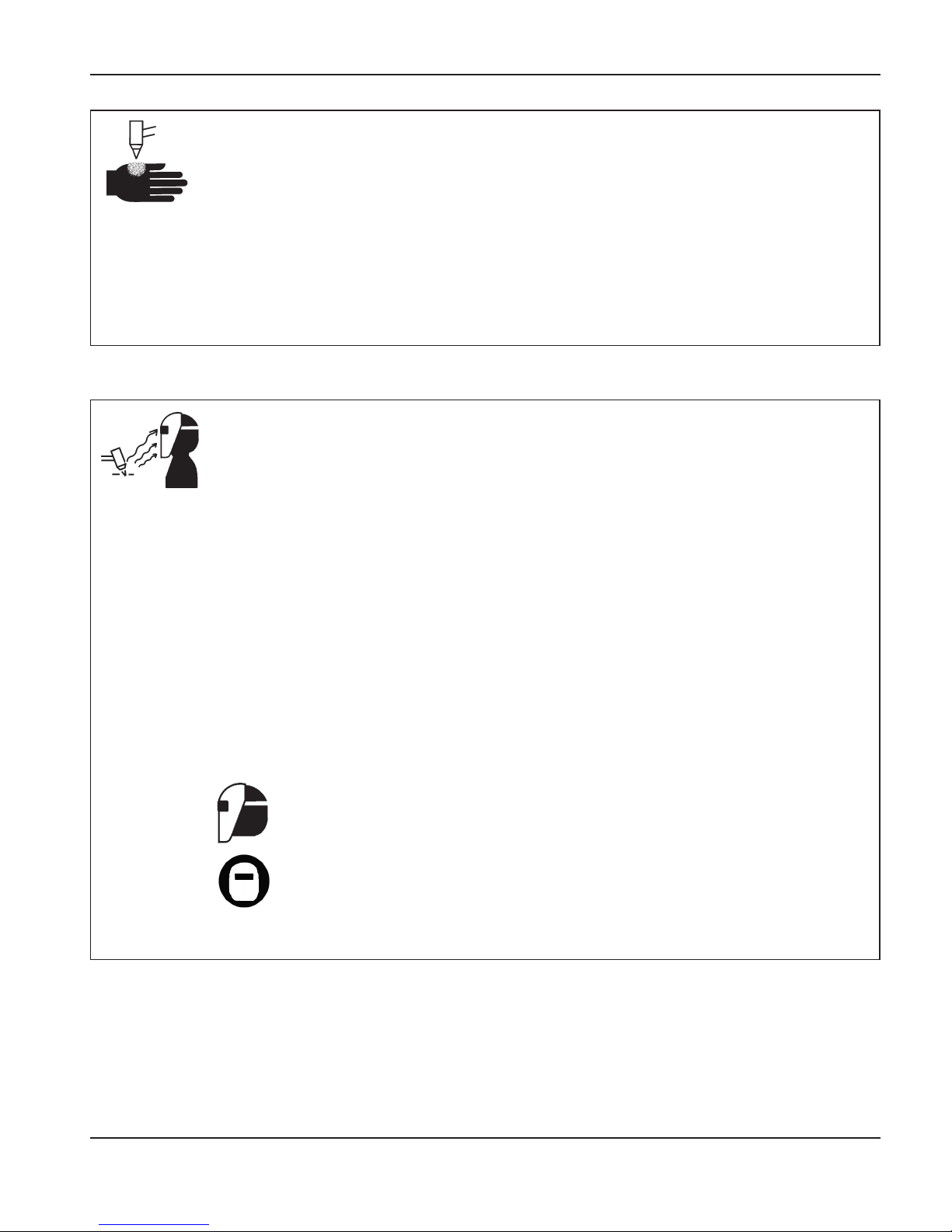
A PLASMAARC CAN CAUSE INJURYAND BURNS
The plasma arc will cut quickly through gloves
and skin.
• Keep away from the torch tip.
• Do not hold metal near the cutting path.
• Never point the torch toward yourself or others.
Eye Protection Plasma arc rays produce intense
visible and invisible (ultraviolet and infrared) rays
that can burn eyes and skin.
• Use eye protection in accordance with applicable
national or local codes.
• Wear eye protection (safety glasses or goggles
with side shields, and a welding helmet) with
appropriate lens shading to protect your eyes
from the arc’s ultraviolet and infrared rays.
Lens Shade
Arc Current AWS (USA) ISO 4850
Up to 100 A No. 8 No. 11
100-200 A No. 10 No. 11-12
200-400 A No. 12 No. 13
Over 400 A No. 14 No. 14
ARC RAYS CAN BURN EYES AND SKIN
Skin Protection Wear protective clothing to
protect against burns caused by ultraviolet light,
sparks and hot metal.
• Gauntlet gloves, safety shoes and hat.
• Flame-retardant clothing to cover all exposed
areas.
• Cuffless trousers to prevent entry of sparks
and slag.
• Remove any combustibles, such as a butane
lighter or matches, from your pockets before
cutting.
Cutting Area Prepare the cutting area to reduce
reflection and transmission of ultraviolet light:
• Paint walls and other surfaces with dark colors to
reduce reflection.
• Use protective screens or barriers to protect
others from flash and glare.
• Warn others not to watch the arc. Use placards
or signs.
Page 17
1-6 Hypertherm Plasma Systems
11-98
SAFETY
• Never lubricate cylinder valves or regulators
with oil or grease.
• Use only correct gas cylinders, regulators,
hoses and fittings designed for the specific
application.
• Maintain all compressed gas equipment and
associated parts in good condition.
• Label and color-code all gas hoses to identify
the type of gas in each hose. Consult applicable
national or local codes.
GAS CYLINDERS CAN
EXPLODE IF DAMAGED
COMPRESSED GAS EQUIPMENT SAFETY
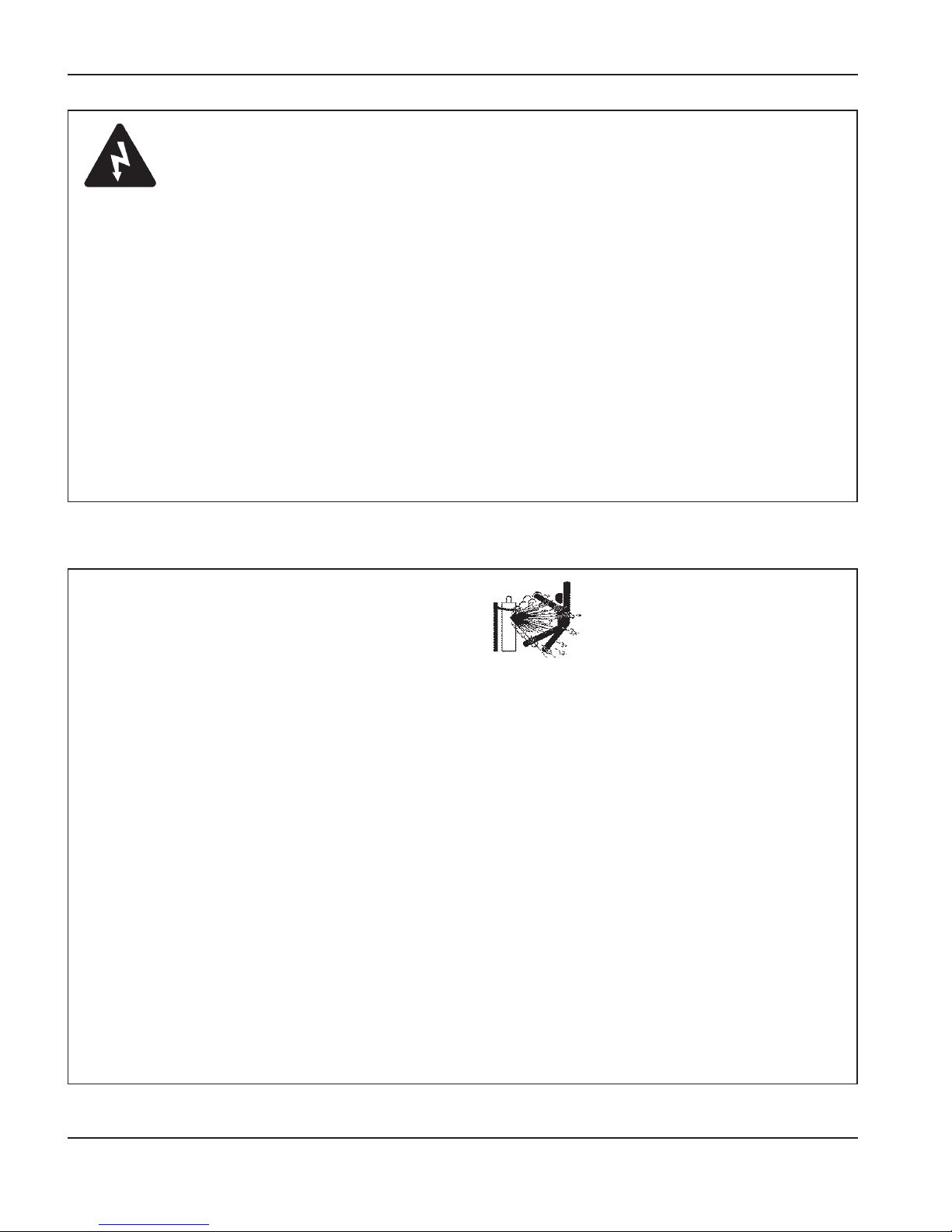
Gas cylinders contain gas under high pressure.
If damaged, a cylinder can explode.
• Handle and use compressed gas cylinders in
accordance with applicable national or local
codes.
• Never use a cylinder that is not upright and
secured in place.
• Keep the protective cap in place over valve
except when the cylinder is in use or connected
for use.
• Never allow electrical contact between the
plasma arc and a cylinder.
• Never expose cylinders to excessive heat,
sparks, slag or open flame.
• Never use a hammer, wrench or other tool to
open a stuck cylinder valve.
Work Cable Attach the work cable securely to the
workpiece or the work table with good metal-tometal contact. Do not connect it to the piece that
will fall away when the cut is complete.
Work Table Connect the work table to an earth
ground, in accordance with appropriate national or
local electrical codes.
GROUNDING SAFETY
Input Power
• Be sure to connect the power cord ground wire
to the ground in the disconnect box.
• If installation of the plasma system involves
connecting the power cord to the power supply,
be sure to connect the power cord ground wire
properly.
• Place the power cord's ground wire on the stud
first, then place any other ground wires on top
of the power cord ground. Fasten the retaining
nut tightly.
• Tighten all electrical connections to avoid
excessive heating.
Page 18

Hypertherm Plasma Systems 1-7
8-01
SAFETY
Prolonged exposure to noise from cutting or
gouging can damage hearing.
• Use approved ear protection when using
plasma system.
• Warn others nearby about the noise hazard.
Frozen pipes may be damaged or can burst if
you attempt to thaw them with a plasma torch.
NOISE CAN DAMAGE HEARING
A PLASMAARC
CAN DAMAGE
FROZEN PIPES
Pacemaker and hearing aid operation can be
affected by magnetic fields from high currents.
Pacemaker and hearing aid wearers should
consult a doctor before going near any plasma
arc cutting and gouging operations.
To reduce magnetic field hazards:
• Keep both the work cable and the torch lead
to one side, away from your body.
• Route the torch leads as close as possible to
the work cable.
• Do not wrap or drape the torch lead or work
cable around your body.
• Keep as far away from the power supply as
possible.
PACEMAKER AND
HEARING AID OPERATION
ADDITIONAL SAFETY INFORMATION
1. ANSI Standard Z49.1,
Safety in Welding and Cutting,
American Welding Society, 550 LeJeune Road
P.O. Box 351020, Miami, FL 33135
2. ANSI Standard Z49.2,
Fire Prevention in the Use of Cutting
and Welding Processes,
American National Standards
Institute, 1430 Broadway, New York, NY 10018
3. ANSI Standard Z87.1,
Safe Practices for Occupation and
Educational Eye and Face Protection,
American National
Standards Institute, 1430 Broadway, New York, NY 10018
4. AWS F4.1,
Recommended Safe Practices for the Preparation
for Welding and Cutting of Containers and Piping That Have
Held Hazardous Substances,
American Welding Society,
550 LeJeune Road, P.O. Box 351040, Miami, FL 33135
5. AWS F5.2,
Recommended Safe Practices for Plasma Arc
Cutting,
American Welding Society, 550 LeJeune Road, P.O.
Box 351040, Miami, FL 33135
6. CGA Pamphlet P-1,
Safe Handling of Compressed Gases in
Cylinders,
Compressed Gas Association, 1235 Jefferson
Davis Highway, Arlington, VA 22202
7. CSA Standard W117.2,
Code for Safety in Welding and
Cutting,
Canadian Standards Association Standard Sales
178 Rexdale Boulevard, Rexdale, Ontario M9W 1R3,
Canada
8. NFPA Standard 51B,
Cutting and Welding Processes,
National Fire Protection Association, 470 Atlantic Avenue,
Boston, MA 02210
9. NFPA Standard 70–1978,
National Electrical Code,
National
Fire Protection Association, 470 Atlantic Avenue, Boston, MA
02210
10. OSHA,
Safety and Health Standards,
29FR 1910
U.S. Government Printing Office, Washington, D.C. 20402
Page 19
1-8 Hypertherm Plasma Systems
SAFETY
WARNING LABEL
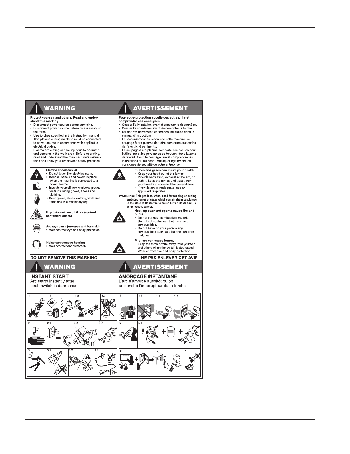
This warning label is affixed to some power supplies. It is
important that the operator and maintenance technician
understand the intent of these warning symbols as
described. The numbered text corresponds to the numbered
boxes on the label.
1. Cutting sparks can cause
explosion or fire.
1.1 Keep flammables away from
cutting.
1.2 Keep a fire extinguisher nearby,
and have a watchperson ready to
use it.
1.3 Do not cut on any closed
containers.
2. The plasma arc can cause injury
and burns.
2.1 Turn off power before
disassembling torch.
2.2 Do not hold the material near
cutting path.
2.3 Wear complete body protection.
3. Electric shock from torch or wiring
can kill. Protect yourself from
electric shock.
3.1 Wear insulating gloves. Do not
wear wet or damaged gloves.
3.2 Insulate yourself from work and
ground.
3.3 Disconnect input plug or power
before working on machine.
4. Breathing cutting fumes can be
hazardous to your health.
4.1 Keep your head out of the fumes.
4.2 Use forced ventilation or local
exhaust to remove the fumes.
4.3 Use ventilating fan to remove the
fumes.
5. Arc rays can burn eyes and injure
skin.
5.1 Wear hat and safety glasses. Use
ear protection and button shirt
collar. Use welding helmet with
correct shade of filter. Wear
complete body protection.
6. Become trained and read the
instructions before working on the
machine or cutting.
7. Do not remove or paint over
(cover) warning labels.
110391 Rev A
Page 20

8-06
Hypertherm Systèmes plasma 1a-1
Section 1a
SÉCURITÉ
Dans cette section :
Identifier les consignes de sécurité ........................................................................................1a-2
Suivre les instructions de sécurité..........................................................................................1a-2
Le coupage peut provoquer un incendie ou une explosion....................................................1a-2
Les chocs électriques peuvent être fatals ..............................................................................1a-3
L’électricité statique peut endommager les cartes de circuits imprimés.................................1a-3
Les vapeurs toxiques peuvent provoquer des blessures ou la mort ......................................1a-4
L’arc plasma peut provoquer des blessures ou des brûlures.................................................1a-5
Les rayons de l’arc peuvent brûler les yeux et la peau ..........................................................1a-5
Mise à la masse et à la terre ..................................................................................................1a-6
Sécurité des bouteilles de gaz comprimé...............................................................................1a-6
Les bouteilles de gaz comprimé peuvent exploser en cas de dommages.............................1a-6
Le bruit peut provoquer des problèmes auditifs .....................................................................1a-7
Pacemakers et prothèses auditives .......................................................................................1a-7
Un arc plasma peut endommager les tuyaux gelés ...............................................................1a-7
Étiquettes de sécurité.............................................................................................................1a-8
Page 21
11-98
1a-2 Hypertherm Systèmes plasma
SÉCURITÉ
IDENTIFIER LES CONSIGNES
DE SÉCURITÉ
Les symboles indiqués dans cette section sont
utilisés pour identifier les risques éventuels. Si vous trouvez
un symbole de sécurité, que ce soit dans ce manuel ou sur
l’équipement, soyez conscient des risques de blessures et
suivez les instructions correspondantes afin d’éviter ces
risques.
SUIVRE LES INSTRUCTIONS
DE SÉCURITÉ
Lire attentivement toutes les consignes de
sécurité dans le présent manuel et sur les étiquettes de
sécurité se trouvant sur la machine.
• Les étiquettes de sécurité doivent rester lisibles.
Remplacer immédiatement les étiquettes manquantes ou
abîmées.
• Apprendre à faire fonctionner la machine et à utiliser
correctement les commandes. Ne laisser personne utiliser
la machine sans connaître son fonctionnement.
• Garder la machine en bon état. Des modifications non
autorisées sur la machine peuvent engendrer des
problèmes de sécurité et raccourcir la durée d’utilisation
de l’équipement.
DANGER AVERTISSEMENT PRÉCAUTION
Les signaux DANGER ou AVERTISSEMENT sont utilisés
avec un symbole de sécurité, DANGER correspondant aux
risques les plus sérieux.
• Les étiquettes de sécurité DANGER et AVERTISSEMENT
sont situées sur la machine pour signaler certains dangers
spécifiques.
• Les messages d’AVERTISSEMENT précèdent les
instructions d’utilisation expliquées dans ce manuel et
signalent les risques de blessures ou de mort au cas où
ces instructions ne seraient pas suivies correctement.
• Les messages de PRÉCAUTION précèdent les
instructions d’utilisation contenues dans ce manuel et
signalent que le matériel risque d’être endommagé si les
instructions ne sont pas suivies correctement.
Prévention des incendies
• Avant de commencer, s’assurer que la zone de coupage
ne présente aucun danger. Conserver un extincteur à
proximité.
• Éloigner toute matière inflammable à une distance d’au
moins 10 m du poste de coupage.
• Tremper le métal chaud ou le laisser refroidir avant de le
manipuler ou avant de le mettre en contact avec des
matériaux combustibles.
• Ne jamais couper des récipients pouvant contenir des
matières inflammables avant de les avoir vidés et
nettoyés correctement.
• Aérer toute atmosphère potentiellement inflammable
avant d’utiliser un système plasma.
• Lors de l’utilisation d’oxygène comme gaz plasma, un
système de ventilation par aspiration est nécessaire.
Prévention des explosions
• Ne pas couper en présence de poussière ou de vapeurs.
• Ne pas couper de bouteilles, de tuyaux ou autres
récipients fermés et pressurisés.
• Ne pas couper de récipients contenant des matières
combustibles.
LE COUPAGE PEUT PROVOQUER
UN INCENDIE OU UNE EXPLOSION
AVERTISSEMENT
Risque d’explosion
argon-hydrogène et méthane
L’hydrogène et le méthane sont des gaz inflammables et
potentiellement explosifs. Conserver à l’écart de toute
flamme les bouteilles et tuyaux contenant des mélanges à
base d’hydrogène ou de méthane. Maintenir toute flamme et
étincelle à l’écart de la torche lors de l’utilisation d’un plasma
d’argon-hydrogène ou de méthane.
AVERTISSEMENT
Détonation de l’hydrogène lors du
coupage de l’aluminium
• Lors du coupage de l’aluminium sous l’eau, ou si l’eau
touche la partie inférieure de la pièce d’aluminium, de
l’hydrogène libre peut s’accumuler sous la pièce à couper
et détonner lors du coupage plasma.
• Installer un collecteur d’aération au fond de la table à eau
afin d’éliminer les risques de détonation de l’hydrogène.
Se référer à l’annexe du manuel pour plus de
renseignements sur les collecteurs d’aération.
Page 22
8-06
Toucher une pièce électrique sous tension peut provoquer
un choc électrique fatal ou des brûlures graves.
• La mise en fonctionnement du système plasma ferme un
circuit électrique entre la torche et la pièce à couper. La
pièce à couper et tout autre élément en contact avec
cette pièce font partie du circuit électrique.
• Ne jamais toucher le corps de la torche, la pièce à
couper ou l’eau de la table à eau pendant le
fonctionnement du système plasma.
Prévention des chocs électriques
Tous les systèmes plasma Hypertherm utilisent des hautes
tensions pour le coupage (souvent de 200 à 400 V). On
doit prendre les précautions suivantes quand on utilise le
système plasma :
• Porter des bottes et des gants isolants et garder le corps
et les vêtements au sec.
• Ne pas se tenir, s’asseoir ou se coucher sur une surface
mouillée, ni la toucher quand on utilise le système
plasma.
• S’isoler de la surface de travail et du sol en utilisant des
tapis isolants secs ou des couvertures assez grandes
pour éviter tout contact physique avec le travail ou le sol.
S’il s’avère nécessaire de travailler dans ou près d’un
endroit humide, procéder avec une extrême prudence.
• Installer un sectionneur avec fusibles appropriés, à
proximité de la source de courant. Ce dispositif permet à
l’opérateur d’arrêter rapidement la source de courant en
cas d’urgence.
• En cas d’utilisation d’une table à eau, s’assurer que cette
dernière est correctement mise à la terre.
LES CHOCS ÉLECTRIQUES PEUVENT ÊTRE FATALS
• Installer et mettre à la terre l’équipement selon les
instructions du présent manuel et conformément aux
codes électriques locaux et nationaux.
• Inspecter fréquemment le cordon d’alimentation primaire
pour s’assurer qu’il n’est ni endommagé, ni fendu.
Remplacer immédiatement un cordon endommagé.
Un câble dénudé peut tuer.
• Inspecter et remplacer les câbles de la torche qui sont
usés ou endommagés.
• Ne pas saisir la pièce à couper ni les chutes lors du
coupage. Laisser la pièce à couper en place ou sur la
table de travail, le câble de retour connecté lors du
coupage.
• Avant de vérifier, de nettoyer ou de remplacer les pièces
de la torche, couper l’alimentation ou débrancher la prise
de courant.
• Ne jamais contourner ou court-circuiter les verrouillages
de sécurité.
• Avant d’enlever le capot du système ou de la source de
courant, couper l’alimentation électrique. Attendre ensuite 5 minutes pour que les condensateurs se
déchargent.
• Ne jamais faire fonctionner le système plasma sans que
les capots de la source de courant ne soient en place.
Les raccords exposés de la source de courant sont
extrêmement dangereux.
• Lors de l’installation des connexions, attacher tout
d’abord la prise de terre appropriée.
• Chaque système plasma Hypertherm est conçu pour
être utilisé uniquement avec des torches Hypertherm
spécifiques. Ne pas utiliser des torches inappropriées
qui pourraient surchauffer et présenter des risques pour
la sécurité.
On doit prendre les précautions qui s’imposent quand on
manipule les circuits imprimés.
L’ÉLECTRICITÉ STATIQUE PEUT ENDOMMAGER
LES CARTES DE CIRCUITS IMPRIMÉS
• On doit ranger les cartes de circuits imprimés dans des
contenants antistatiques.
• On doit porter un bracelet antistatique quand on
manipule les cartes de circuits imprimés.
Hypertherm Systèmes plasma 1a-3
SÉCURITÉ
Page 23

8-06
1a-4 Hypertherm Systèmes plasma
SÉCURITÉ
L’arc plasma est lui-même la source de chaleur utilisée
pour le coupage. Par conséquent, bien que l’arc plasma
n’ait pas été reconnu comme une source de vapeurs
toxiques, le matériau coupé peut être une source de
vapeurs ou de gaz toxiques qui épuisent l’oxygène.
Les vapeurs produites varient selon le métal coupé. Les
métaux qui peuvent dégager des vapeurs toxiques
comprennent, entre autres, l’acier inoxydable, l’acier au
carbone, le zinc (galvanisé) et le cuivre.
Dans certains cas, le métal peut être revêtu d’une
substance susceptible de dégager des vapeurs toxiques.
Les revêtements toxiques comprennent entre autres, le
plomb (dans certaines peintures), le cadmium (dans
certaines peintures et enduits) et le béryllium.
Les gaz produits par le coupage plasma varient selon le
matériau à couper et la méthode de coupage, mais ils
peuvent comprendre l’ozone, les oxydes d’azote, le
chrome hexavalent, l’hydrogène et autres substances
présentes dans le matériau coupé ou en émanent.
On doit prendre les précautions qui s’imposent pour
réduire au minimum l’exposition aux vapeurs produites par
tout processus industriel. Selon la composition chimique et
la concentration des vapeurs (ainsi que d’autres facteurs
comme la ventilation), il peut y avoir un risque de maladie
physique, comme des malformations ou le cancer.
Il incombe au propriétaire du matériel et du site de vérifier
la qualité de l’air dans le secteur où l’on utilise le matériel
et de s’assurer que la qualité de l’air sur les lieux de travail
répond aux normes et réglementation locales et nationales.
LES VAPEURS TOXIQUES PEUVENT PROVOQUER
DES BLESSURES OU LA MORT
Le niveau de qualité de l’air dans tout lieu de travail
dépend des variables propres au site comme :
• Type de table (humide, sèche, sous l’eau).
• Composition du matériau, fini de la surface et
composition des revêtements.
• Volume de matériau enlevé.
• Durée du coupage ou du gougeage.
• Dimensions, volume d’air, ventilation et filtration de la
zone de travail.
• Équipement de protection individuelle.
• Nombre de systèmes de soudage et de coupage en
fonctionnement.
• Autres procédés du site qui peuvent produire des
vapeurs.
Si les lieux de travail doivent être conformes aux
règlements nationaux ou locaux, seuls les contrôles ou les
essais effectués au site peuvent déterminer si celui-ci se
situe au-dessus ou au-dessous des niveaux admissibles.
Pour réduire le risque d’exposition aux vapeurs :
• Éliminer tout revêtement et solvant du métal avant le
coupage.
• Utiliser la ventilation d’extraction locale pour éliminer les
vapeurs de l’air..
• Ne pas inhaler les vapeurs. Porter un respirateur à
adduction d’air quand on coupe des métaux revêtus
d’éléments toxiques ou qui en contiennent ou sont
susceptibles d’en contenir.
• S’assurer que les personnes qui utilisent un matériel de
soudage ou de coupage ainsi que les dispositifs de
respiration par adduction d’air sont qualifiés et ont reçu
la formation sur la bonne utilisation d’un tel matériel.
• Ne jamais couper les contenants dans lesquels il peut y
avoir des matériaux toxiques. En premier lieu, vider et
nettoyer correctement le contenant.
• Contrôler ou éprouver la qualité de l’air au site selon les
besoins.
• Consulter un expert local pour mettre en œuvre un plan
du site afin d’assurer une qualité de l’air sûre.
Page 24
5-02
Torches à allumage instantané
L’arc plasma s’allume immédiatement après que la torche
soit mise en marche.
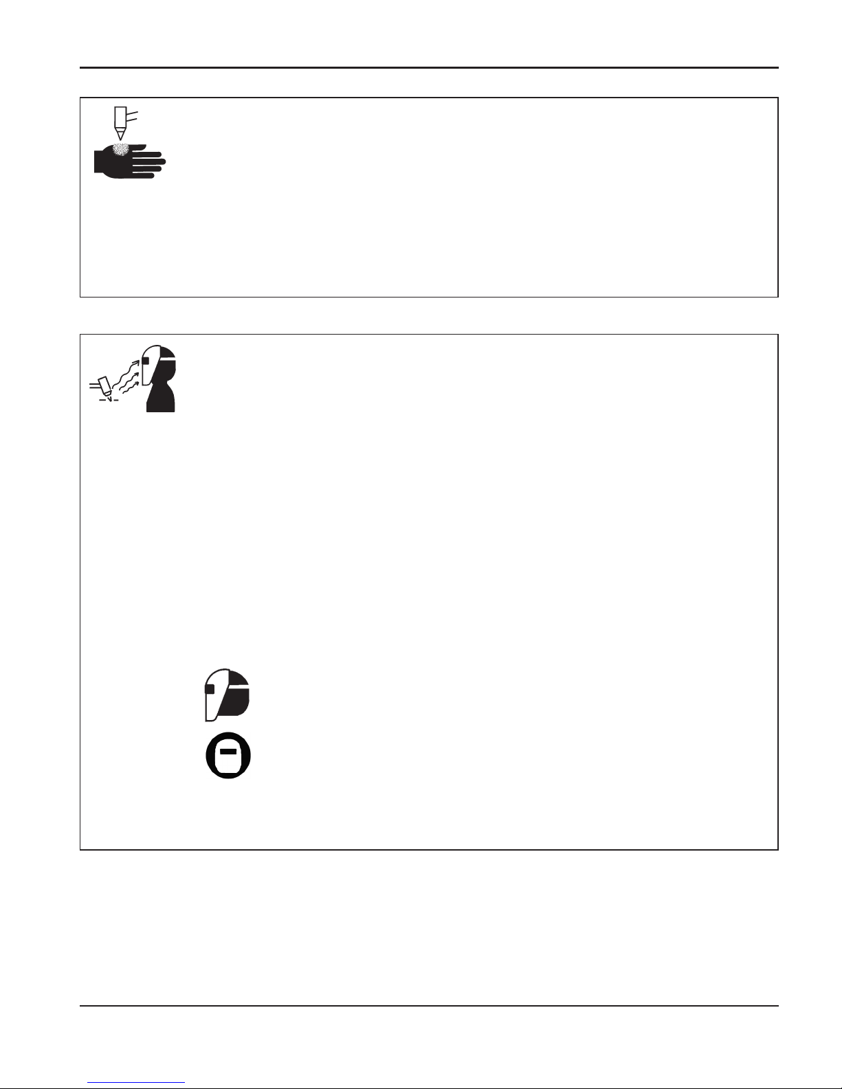
L’ARC PLASMA PEUT PROVOQUER DES BLESSURES OU DES BRÛLURES
L’arc plasma coupe facilement les gants et la peau.
• Rester éloigné de l’extrémité de la torche.
• Ne pas tenir de métal près de la trajectoire de coupe.
• Ne jamais pointer la torche vers soi ou d’autres
personnes.
Protection des yeux Les rayons de l’arc plasma
produisent de puissants rayons visibles ou invisibles
(ultraviolets et infrarouges) qui peuvent brûler les yeux et
la peau.
• Utiliser des lunettes de sécurité conformément aux
codes locaux ou nationaux en vigueur.
• Porter des lunettes de protection (lunettes ou masque
muni d’écrans latéraux et encore masque de soudure)
avec des verres teintés appropriés pour protéger les
yeux des rayons ultraviolets et infrarouges de l’arc.
Puissance des
verres teintés
Courant de l’arc AWS (É.-U.) ISO 4850
Jusqu’à 100 A N
o
8N
o
11
100-200 A N
o
10 No11-12
200-400 A N
o
12 No13
Plus de 400 A N
o
14 No14
LES RAYONS DE L’ARC PEUVENT BRÛLER LES YEUX ET LA PEAU
Protection de la peau Porter des vêtements de sécurité
pour se protéger contre les brûlures que peuvent causer
les rayons ultraviolets, les étincelles et le métal brûlant :
• Gants à crispin, chaussures et casque de sécurité.
• Vêtements ignifuges couvrant toutes les parties
exposées du corps.
• Pantalon sans revers pour éviter que des étincelles ou
des scories puissent s’y loger.
• Avant le coupage, retirer de ses poches tout objet
combustible comme les briquets au butane ou les
allumettes.
Zone de coupage Préparer la zone de coupage afin de
réduire la réverbération et la transmission de la lumière
ultraviolette :
• Peindre les murs et autres surfaces de couleur sombre
pour réduire la réflexion de la lumière.
• Utiliser des écrans et autres dispositifs de protection afin
de protéger les autres personnes de la lumière et de la
réverbération.
• Prévenir les autres personnes de ne pas regarder l’arc.
Utiliser des affiches ou des panneaux.
Hypertherm Systèmes plasma 1a-5
SÉCURITÉ
Page 25
11-98
1a-6 Hypertherm Systèmes plasma
SÉCURITÉ
• Ne jamais lubrifier les robinets des bouteilles ou les
régulateurs avec de l’huile ou de la graisse.
• Utiliser uniquement les bouteilles, régulateurs, tuyaux et
accessoires appropriés et conçus pour chaque
application spécifique.
• Entretenir l’équipement et les pièces d’équipement à gaz
comprimé afin de les garder en bon état.
• Étiqueter et coder avec des couleurs tous les tuyaux de
gaz afin d’identifier le type de gaz contenu dans chaque
tuyau. Se référer aux codes locaux ou nationaux en
vigueur.
LES BOUTEILLES DE
GAZ COMPRIMÉ
PEUVENT EXPLOSER
EN CAS DE DOMMAGES
SÉCURITÉ DES BOUTEILLES
DE GAZ COMPRIMÉ
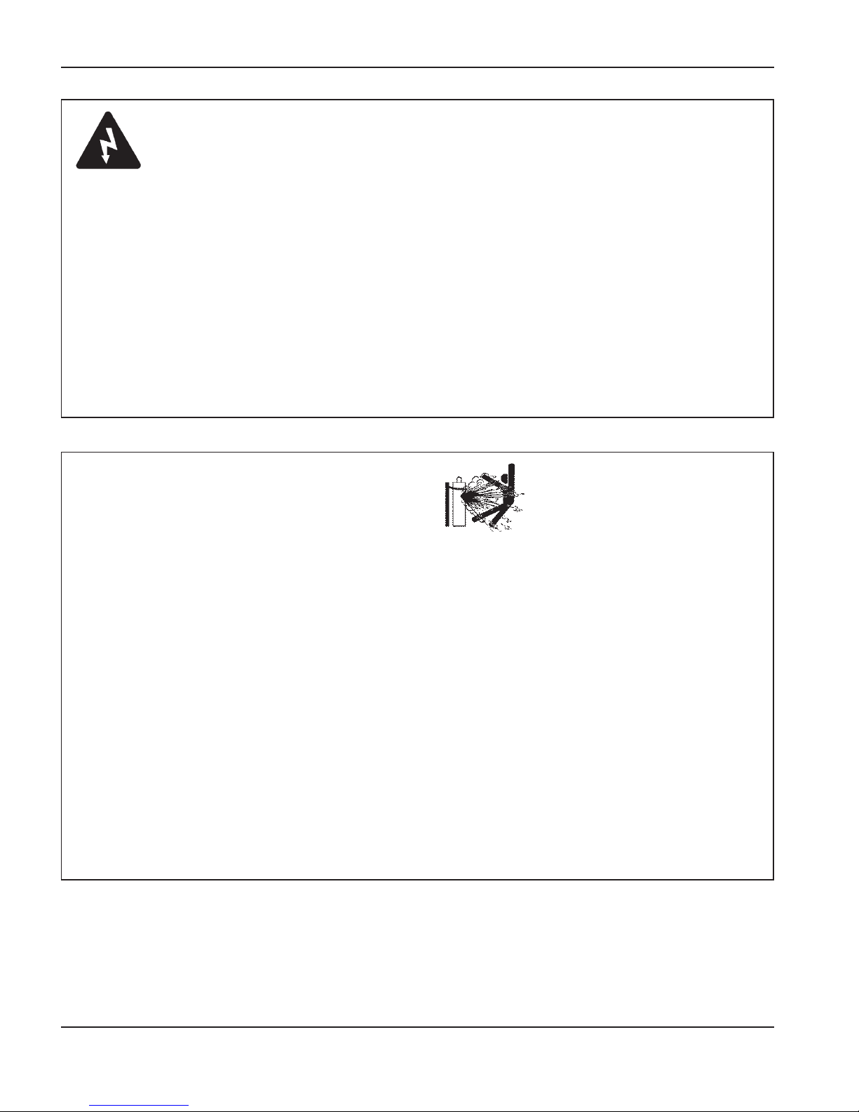
Les bouteilles de gaz contiennent du gaz à haute pression.
Si une bouteille est endommagée, elle peut exploser.
• Manipuler et utiliser les bouteilles de gaz comprimé
conformément aux codes locaux ou nationaux.
• Ne jamais utiliser une bouteille qui n’est pas placée à la
verticale et bien assujettie.
• Le capuchon de protection doit être placé sur le robinet
sauf si la bouteille est en cours d’utilisation ou connectée
pour utilisation.
• Éviter à tout prix le contact électrique entre l’arc plasma
et une bouteille.
• Ne jamais exposer des bouteilles à une chaleur
excessive, aux étincelles, aux scories ou aux flammes
nues.
• Ne jamais utiliser des marteaux, des clés ou d’autres
outils pour débloquer le robinet des bouteilles.
Câble de retour Bien fixer le câble de retour (ou de
masse) à la pièce à couper ou à la table de travail de
façon à assurer un bon contact métal-métal. Ne pas fixer
le câble de retour à la partie de la pièce qui doit se
détacher.
Table de travail Raccorder la table de travail à la terre,
conformément aux codes de sécurité locaux ou nationaux
appropriés.
MISE À LA MASSE ET À LATERRE
Alimentation
• S’assurer que le fil de terre du cordon d’alimentation est
connecté à la terre dans le coffret du sectionneur.
• S’il est nécessaire de brancher le cordon d’alimentation
à la source de courant lors de l’installation du système,
s’assurer que le fil de terre est correctement branché.
• Placer tout d’abord le fil de terre du cordon
d’alimentation sur le plot de mise à la terre puis placer
les autres fils de terre par-dessus. Bien serrer l’écrou de
retenue.
• S’assurer que toutes les connexions sont bien serrées
pour éviter la surchauffe.
Page 26
8-01
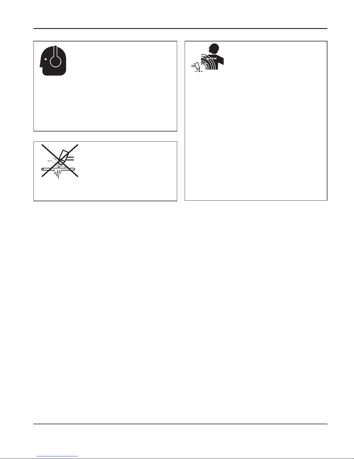
Une exposition prolongée au bruit du coupage ou du
gougeage peut provoquer des problèmes auditifs.
• Utiliser un casque de protection homologué lors de
l’utilisation du système plasma.
• Prévenir les personnes aux alentours des risques
encourus en cas d’exposition au bruit.
Les tuyaux gelés peuvent être endommagés ou éclater si
l'on essaie de les dégeler avec une torche plasma.
LE BRUIT PEUT PROVOQUER
DES PROBLÈMES AUDITIFS
UN ARC PLASMA PEUT
ENDOMMAGER LES
TUYAUX GELÉS
Les champs magnétiques produits par les courants à
haute tension peuvent affecter le fonctionnement des
prothèses auditives et des pacemakers. Les personnes
portant ce type d’appareil doivent consulter un médecin
avant de s’approcher d’un lieu où s’effectue le coupage
ou le gougeage plasma.
Pour réduire les risques associés aux champs
magnétiques :
• Garder loin de soi et du même côté du corps le câble
de retour et le faisceau de la torche.
• Faire passer le faisceau de la torche le plus près
possible du câble de retour.
• Ne pas s’enrouler le faisceau de la torche ou le câble
de retour autour du corps.
• Se tenir le plus loin possible de la source de courant.
PACEMAKERS ET
PROTHÈSES AUDITIVES
Hypertherm Systèmes plasma 1a-7
SÉCURITÉ
Page 27
1a-8 Hypertherm Systèmes plasma
SÉCURITÉ
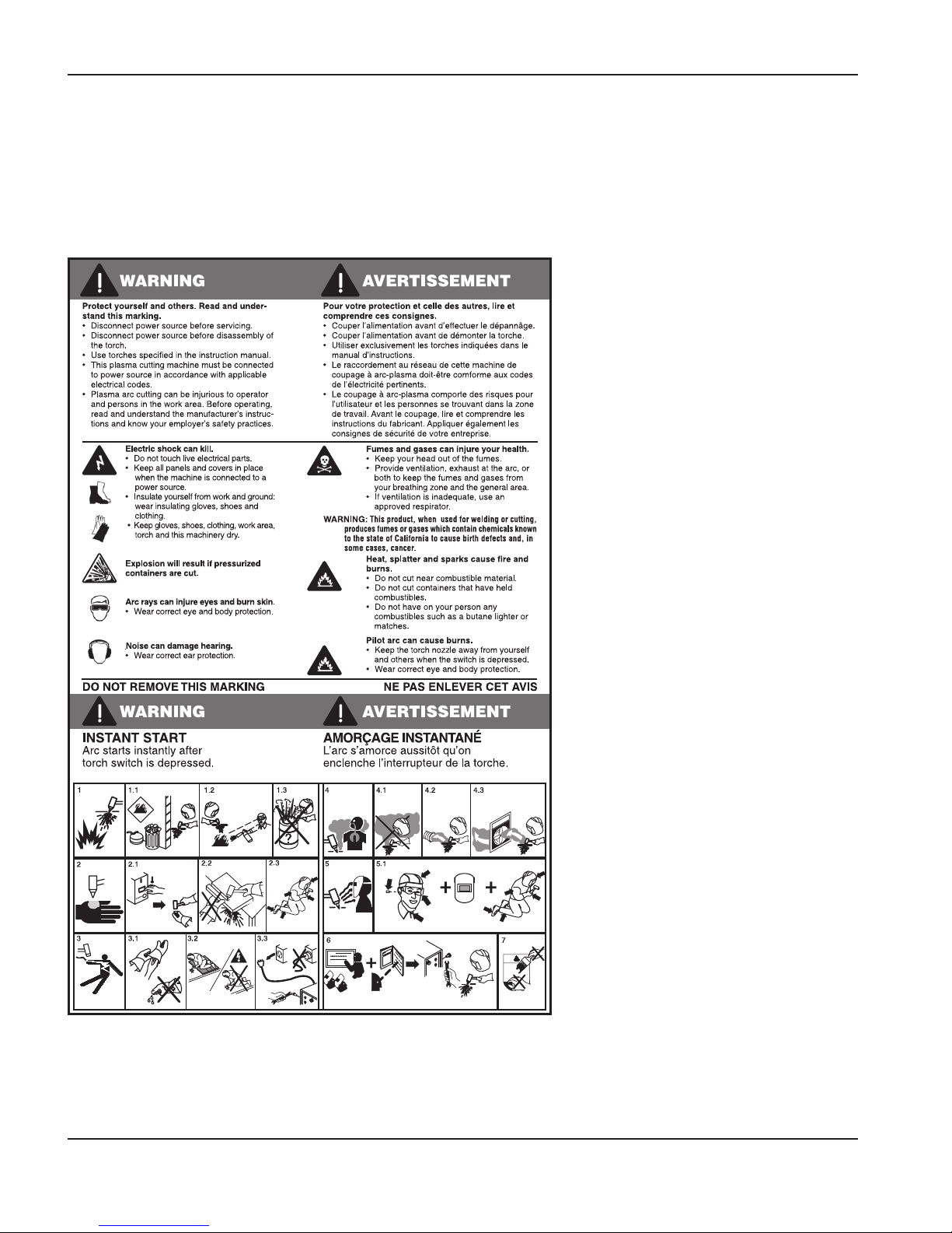
Étiquette de sécurité
Cette étiquette est affichée sur la source de courant. Il est important que
l’utilisateur et le technicien de maintenance comprennent la signification
des symboles de sécurité. Les numéros de la liste correspondent aux
numéros des images.
1. Les étincelles produites par le coupage
peuvent provoquer une explosion ou un
incendie.
1.1 Pendant le coupage, éloigner toute
matière inflammable.
1.2 Conserver un extincteur à proximité et
s’assurer qu’une personne soit prête à
l’utiliser.
1.3 Ne jamais couper de récipients fermés.
2. L’arc plasma peut provoquer des
blessures et des brûlures.
2.1 Couper l’alimentation avant de démonter
la torche.
2.2 Ne pas tenir la surface à couper près de
la trajectoire de coupe.
2.3 Porter des vêtements de protection
couvrant tout le corps.
3. Un choc électrique causé par la torche
ou les câbles peut être fatal. Se protéger
contre les risques de chocs électriques.
3.1 Porter des gants isolants. Ne pas porter
de gants mouillés ou abîmés.
3.2 S’isoler de la surface de travail et du sol.
3.3 Débrancher la prise ou la source de
courant avant de manipuler
l’équipement.
4. L’inhalation des vapeurs produites par le
coupage peut être dangereuse pour la
santé.
4.1 Garder le visage à l’écart des vapeurs.
4.2 Utiliser un système de ventilation par
aspiration ou d’échappement localisé
pour dissiper les vapeurs.
4.3 Utiliser un ventilateur pour dissiper les
vapeurs.
5. Les rayons de l’arc peuvent brûler les
yeux et provoquer des lésions de la
peau.
5.1 Porter un casque et des lunettes de
sécurité. Se protéger les oreilles et
porter une chemise dont le col peut être
déboutonné. Porter un casque de
soudure dont la protection filtrante est
suffisante. Porter des vêtements
protecteurs couvrant la totalité du corps.
6. Se former à la technique du coupage et
lire les instructions avant de manipuler
l’équipement ou de procéder au
coupage.
7. Ne pas retirer ou peindre (recouvrir) les
étiquettes de sécurité.
110391 Rev A
Page 28

8-06
Hypertherm Sistemas plasma 1b-1
Seccíon 1b
SEGURIDAD
En esta sección:
Reconocimiento de información de seguridad .......................................................................1b-2
Siga las instrucciones de seguridad.......................................................................................1b-2
Los cortes pueden provocar incendios o explosiones............................................................1b-2
El choque eléctrico puede provocar la muerte.......................................................................1b-3
Electricidad estática puede dañar tablillas de circuito............................................................1b-3
Humos tóxicos pueden causar lesiones o muerte..................................................................1b-4
El arco de plasma puede causar lesiones y quemaduras......................................................1b-5
Los rayos del arco pueden producir quemaduras en los ojos y en la piel..............................1b-5
Seguridad de toma a tierra.....................................................................................................1b-6
Seguridad de los equipos de gas comprimido .......................................................................1b-6
Los cilindros de gas pueden explotar si están dañados.........................................................1b-6
El ruido puede deteriorar la audición......................................................................................1b-7
Operación de marcapasos y de audífonos.............................................................................1b-7
Un arco plasma puede dañar tubos congelados....................................................................1b-7
Etiquetas de advertencia........................................................................................................1b-8
Page 29
11-98
SEGURIDAD
1b-2 Hypertherm Sistemas plasma
RECONOCIMIENTO DE
INFORMACIÓN DE SEGURIDAD
Los símbolos que se muestran en esta sección se
utilizan para identificar los posibles peligros. Cuando vea
un símbolo de seguridad en este manual o en su máquina,
recuerde que existe la posibilidad de que se produzcan
lesiones personales y siga las instrucciones
correspondientes para evitar el peligro.
SIGA LAS INSTRUCCIONES DE
SEGURIDAD
Lea atentamente todos los mensajes de
seguridad de este manual y las etiquetas de
seguridad en su máquina.
• Mantenga las etiquetas de seguridad de su máquina en
buen estado. Reemplace las etiquetas que se pierdan o
se dañen inmediatamente.
• Aprenda a utilizar la máquina y a utilizar los controles de
la manera correcta. No permita que sea utilizada por
alguien que no conozca su funcionamiento.
• Mantenga su máquina en buenas condiciones de
funcionamiento. La realización de modificaciones no
autorizadas a la máquina puede comprometer la
seguridad y la vida útil de la máquina.
PELIGRO ADVERTENCIA PRECAUCIÓN
Las palabras PELIGRO y ADVERTENCIA se utilizan
conjuntamente con un símbolo de seguridad. La palabra
PELIGRO se utiliza para identificar los mayores peligros.
• Encontrará etiquetas de seguridad con las inscripciones
PELIGRO y ADVERTENCIA en su máquina, junto a
peligros específicos.
• En este manual, la palabra ADVERTENCIA va seguida
de instrucciones que, si no se siguen correctamente,
pueden provocar lesiones e inclusive la muerte.
• En este manual, la palabra PRECAUCIÓN va seguida
de instrucciones que, si no se siguen correctamente,
pueden provocar daños en el equipo.
Prevención ante el fuego
• Asegúrese de que el área sea segura antes de proceder
a cortar. Tenga a mano un extinguidor de incendios.
• Retire todos los materiales inflamables, colocándolos a
por lo menos 10 metros del área de corte.
• Remoje los metales calientes o permita que se enfríen
antes de que entren en contacto con materiales
combustibles.
• Nunca corte depósitos que contengan materiales
inflamables – primero es necesario vaciarlos y limpiarlos
debidamente.
• Antes de realizar cortes en atmósferas potencialmente
inflamables, asegúrese de ventilar bien.
• Al realizar cortes utilizando oxígeno como gas plasma,
se requiere tener un sistema de ventilación de escape.
Prevención ante explosiones
• No corte en atmósferas que contengan polvo o vapores
explosivos
.
• No corte depósitos o tubos a presión ni cualquier
depósito cerrado.
• No corte depósitos que hayan contenido materiales
combustibles.
LOS CORTES PUEDEN PROVOCAR
INCENDIOS O EXPLOSIONES
ADVERTENCIA
Peligro de explosión
Argón-Hidrógeno y metano
El hidrógeno y el metano son gases inflamables que
suponen un peligro de explosión. Mantenga el fuego lejos
de los cilindros y las mangueras que contengan mezclas de
hidrógeno o metano. Mantenga la llama y las chispas lejos
de la antorcha al utilizar metano o argón-hidrógeno como
plasma.
ADVERTENCIA
Detonación de hidrógeno con
el corte de aluminio
• Al cortar aluminio bajo agua o con agua en contacto con
el lado inferior del aluminio, puede acumularse gas
hidrógeno bajo la pieza a cortar y detonar durante la
operación de corte por plasma.
• Instale un múltiple de aireación en el fondo de la mesa de
agua para eliminar la posibilidad de la detonación del
hidrógeno. Consulte la sección del apéndice de este
manual para conocer detalles acerca del múltiple de
aireación.
Page 30
8-06
El contacto directo con piezas eléctricas conectadas puede
provocar un electrochoque fatal o quemaduras graves.
• Al hacer funcionar el sistema de plasma, se completa un
circuito eléctrico entre la antorcha y la pieza a cortar. La
pieza a cortar es una parte del circuito eléctrico, como
también cualquier cosa que se encuentre en contacto
con ella.
• Nunca toque el cuerpo de la antorcha, la pieza a cortar o
el agua en una mesa de agua cuando el sistema de
plasma se encuentre en funcionamiento.
Prevención ante el electrochoque
Todos los sistemas por plasma de Hypertherm usan alto
voltaje en el proceso de corte (son comunes los voltajes
CD de 200 a 400). Tome las siguientes precauciones
cuando se utiliza el equipo de plasma:
• Use guantes y botas aislantes y mantenga el cuerpo
y la ropa secos.
• No se siente, se pare o se ponga sobre cualquier
superficie húmeda cuando esté trabajando con el
equipo.
• Aíslese eléctricamente de la pieza a cortar y de la tierra
utilizando alfombrillas o cubiertas de aislamiento secas
lo suficientemente grandes como para impedir todo
contacto físico con la pieza a cortar o con la tierra. Si su
única opción es trabajar en una área húmeda o cerca de
ella, sea muy cauteloso.
• Instale un interruptor de corriente adecuado en cuanto a
fusibles, en una pared cercana a la fuente de energía.
Este interruptor permitirá al operador desconectar
rápidamente la fuente de energía en caso de
emergencia.
• Al utilizar una mesa de agua, asegúrese de que ésta se
encuentre correctamente conectada a la toma a tierra.
EL CHOQUE ELÉCTRICO PUEDE PROVOCAR LA MUERTE
• Instale este equipo y conéctelo a tierra según el manual
de instrucciones y de conformidad con los códigos
locales y nacionales.
• Inspeccione el cordón de alimentación primaria con
frecuencia para asegurarse de que no esté dañado ni
agrietado. Si el cordón de alimentación primaria está
dañado, reemplácelo inmediatamente. Un cable
pelado puede provocar la muerte.
• Inspeccione las mangueras de la antorcha y
reemplácelas cuando se encuentren dañadas.
• No toque la pieza ni los recortes cuando se está
cortando. Deje la pieza en su lugar o sobre la mesa de
trabajo con el cable de trabajo conectado en todo
momento.
• Antes de inspeccionar, limpiar o cambiar las piezas de la
antorcha, desconecte la potencia primaria o desenchufe
la fuente de energía.
• Nunca evite o descuide los bloqueos de seguridad.
• Antes de retirar la cubierta de una fuente de energía o
del gabinete de un sistema, desconecte la potencia
primaria de entrada. Espere 5 minutos después de
desconectar la potencia primaria para permitir la
descarga de los condensadores.
• Nunca opere el sistema de plasma sin que las tapas de
la fuente de energía estén en su lugar. Las conexiones
expuestas de la fuente de energía presentan un serio
riesgo eléctrico.
• Al hacer conexiones de entrada, conecte el conductor de
conexión a tierra en primer lugar.
• Cada sistema de plasma Hypertherm está diseñado
para ser utilizado sólo con antorchas Hypertherm
específicas. No utilice antorchas diferentes, que podrían
recalentarse y ser peligrosas.
Use precauciones adecuadas cuando maneje tablillas
impresas de circuito
ELECTRICIDAD ESTÁTICA PUEDE
DAÑAR TABLILLAS DE CIRCUITO
• Almacene las tablillas PC en recipientes antiestáticos.
• Use la defensa de muñeca conectada a tierra cuando
maneje tablillas PC.
SEGURIDAD
Hypertherm Sistemas plasma 1b-3
Page 31

8-06
SEGURIDAD
1b-4 Hypertherm Sistemas plasma
El arco plasma es por si solo la fuente de calor que se usa
para cortar. Según esto, aunque el arco de plasma no ha
sido identificado como la fuente de humo tóxico, el material
que se corta puede ser la fuente de humo o gases tóxicos
que vacían el oxígeno.
El humo producido varía según el metal que está
cortándose. Metales que pueden liberar humo tóxico
incluyen, pero no están limitados a, acero inoxidable,
acero al carbón, cinc (galvanizado), y cobre.
En algunos casos, el metal puede estar recubierto con una
sustancia que podría liberar humos tóxicos. Los
recubrimientos tóxicos incluyen, pero no están limitados a,
plomo (en algunas pinturas), cadmio (en algunas pinturas
y rellenos), y berilio.
Los gases producidos por el corte por plasma varían
basándose en el material a cortarse y el método de cortar,
pero pueden incluir ozono, óxidos de nitrógeno, cromo
hexavalente, hidrógeno, y otras substancias, si están
contenidas dentro o liberadas por el material que se corta.
Se debe tener cuidado de minimizar la exposición del
humo producido por cualquier proceso industrial. Según la
composición química y la concentración del humo (al igual
que otros factores, tales como ventilación), puede haber el
riesgo de enfermedad física, tal como defectos de
natividad o cáncer.
Es la responsabilidad del dueño del equipo y instalación el
comprobar la calidad de aire en el lugar donde se está
usando el equipo para garantizar que la calidad del aire en
el lugar de trabajo cumpla con todas las normas y
reglamentos locales y nacionales.
HUMOS TÓXICOS PUEDEN CAUSAR LESIONES O MUERTE
El nivel de la calidad del aire en cualquier lugar de trabajo
relevante depende en variables específicas al sitio tales
como:
• Diseño de mesa (mojada, seca, bajo agua).
• La composición del material, el acabado de la superficie,
y la composición de los recubrimientos.
• Volumen que se quita del material.
• La duración del corte o ranura.
• Tamaño, volumen del aire, ventilación y filtración del
lugar de trabajo.
• Equipo de protección personal.
• Número de sistemas de soldar y cortar en la operación.
• Otros procesos del lugar que pueden producir humo.
Si el lugar de trabajo debe cumplir reglamentos nacionales
o locales, solamente el monitoreo o las pruebas que se
hacen en el lugar pueden determinar si el sitio está encima
o debajo de los niveles permitidos.
Para reducir el riesgo de exposición a humo:
• Quite todos los recubrimientos y solventes del metal
antes de cortar.
• Use ventilación extractora local para quitar humo del
aire.
• No inhale el humo. Use un respirador con fuente propia
de aire cuando corte cualquier metal recubierto con, o
sospechado de contener, elementos tóxicos.
• Garantice que aquéllos usando equipo de soldar o
cortar, al igual que aparatos de respiración con aire
propio de aire, estén capacitados y entrenados en el uso
apropiado de tal equipo.
• Nunca corte recipientes con materiales potencialmente
tóxicos adentro. Primero, vacíe y limpie el recipiente
adecuadamente.
• Monitoree o compruebe la calidad del aire en el sitio
como fuera necesario.
• Consulte con un experto local para realizar un plan al
sitio para garantizar la calidad de aire seguro.
Page 32
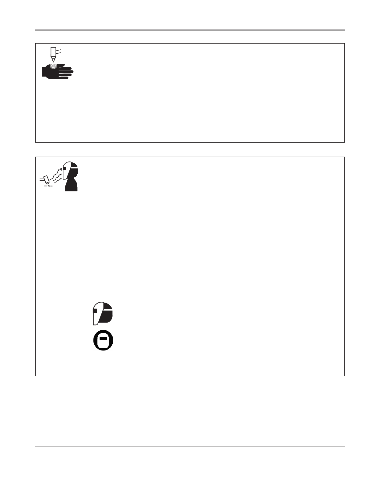
5-02
Antorchas de encendido instantáneo
El arco de plasma se enciende inmediatamente después
de activarse el interruptor de la antorcha.
EL ARCO DE PLASMA PUEDE CAUSAR LESIONES Y QUEMADURAS
El arco de plasma puede cortar a través de guantes y de la
piel con rapidez.
• Manténgase alejado de la punta de la antorcha.
• No sostenga el metal junto al trayecto de corte.
• Nunca apunte la antorcha hacia Ud. mismo o hacia otras
personas.
Protección para los ojos Los rayos del arco de plasma
producen rayos intensos visibles e invisibles (ultravioleta e
infrarrojo) que pueden quemar los ojos y la piel.
• Utilice protección para los ojos de conformidad con los
códigos locales o nacionales aplicables.
• Colóquese protectores para los ojos (gafas o anteojos
protectores con protectores laterales, y bien un casco de
soldar) con lentes con sombreado adecuado para
proteger sus ojos de los rayos ultravioleta e infrarrojos
del arco.
Número del cristal
Corriente del arco AWS (EE.UU.) ISO 4850
Hasta 100A No. 8 No. 11
100-200 A No. 10 No. 11-12
200-400 A No. 12 No. 13
Más de 400 A No. 14 No. 14
LOS RAYOS DEL ARCO PUEDEN PRODUCIR QUEMADURAS
EN LOS OJOS Y EN LAPIEL
Protección para la piel Vista ropa de protección para
proteger la piel contra quemaduras causadas por la
radiación ultravioleta de alta intensidad, por las chispas y
por el metal caliente:
•
Guantes largos, zapatos de seguridad y gorro.
•
Roipa de combustión retardada y que cubra todas las
partes expuestas.
•
Pantalones sin dobladillos para impedir que recojan
chispas y escorias.
•
Retire todo material combustible de los bolsillos, como
encendedores a butano e inclusive cerillas, antes de
comenzar a cortar.
Área de corte Prepare el área de corte para reducir la
reflexión y la transmisión de la luz ultravioleta:
•
Pinte las paredes y demás superficies con colores
oscuros para reducir la reflexión.
•
Utilice pantallas o barreras protectoras para proteger a
los demás de los destellos.
•
Advierta a los demás que no debe mirarse el arco.
Utilice carteles o letreros.
SEGURIDAD
Hypertherm Sistemas plasma 1b-5
Page 33
11-98
SEGURIDAD
1b-6 Hypertherm Sistemas plasma
•
Nunca lubrique reguladores o válvulas de cilindros con
aceite o grasa.
•
Utilice solamente cilindros, reguladores, mangueras y
conectores de gas correctos que hayan sido diseñados
para la aplicación específica.
•
Mantenga todo el equipo de gas comprimido y las piezas
relacionadas en buen estado.
•
Coloque etiquetas y códigos de color en todas las
mangueras de gas para identificar el tipo de gas que
conduce cada una. Consulte los códigos locales o
nacionales aplicables.
LOS CILINDROS DE GAS
PUEDEN EXPLOTAR SI
ESTÁN DAÑADOS
SEGURIDAD DE LOS EQUIPOS DE GAS
COMPRIMIDO
Los cilindros de gas contienen gas bajo alta presión. Un
cilindro dañado puede explotar.
•
Manipule y utilice los cilindros de gas comprimido de
acuerdo con los códigos locales o nacionales aplicables.
•
No use nunca un cilindro que no esté de pie y bien
sujeto.
•
Mantenga la tapa de protección en su lugar encima de la
válvula, excepto cuando el cilindro se encuentre en uso
o conectado para ser utilizado.
•
No permita nunca el contacto eléctrico entre el arco de
plasma y un cilindro.
•
No exponga nunca los cilindros a calor excesivo,
chispas, escorias o llamas.
•
No emplee nunca martillos, llaves u otro tipo de
herramientas para abrir de golpe la válvula del cilindro.
Cable de trabajo La pinza del cable de trabajo debe
estar bien sujetada a la pieza y hacer un buen contacto de
metal a metal con ella o bien con la mesa de trabajo. No
conecte el cable con la parte que va a quedar separada
por el corte.
Mesa de trabajo Conecte la mesa de trabajo a una
buena toma de tierra, de conformidad con los códigos
eléctricos nacionales o locales apropiados.
Potencia primaria de entrada
SEGURIDAD DE TOMAA TIERRA
• Asegúrese de que el alambre de toma a tierra del
cordón de alimentación está conectado al terminal de
tierra en la caja del interruptor de corriente.
• Si la instalación del sistema de plasma supone la
conexión del cordón de alimentación primaria a la fuente
de energía, asegúrese de conectar correctamente el
alambre de toma a tierra del cordón de alimentación
primaria.
• Coloque en primer lugar el alambre de toma a tierra del
cordón de alimentación primaria en el espárrago luego
coloque cualquier otro alambre de tierra sobre el
conductor de tierra del cable. Ajuste firmemente la
tuerca de retención.
• Asegúrese de que todas las conexiones eléctricas están
firmemente realizadas para evitar sobrecalentamientos.
Page 34
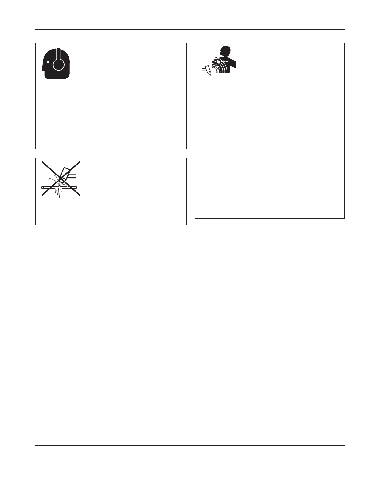
8-01
La exposición prolongada al ruido propio de las
operaciones de corte y ranurado puede dañar la
audición.
•
Utilice un método de protección de los oídos aprobado
al utilizar el sistema de plasma.
•
Advierta a las demás personas que se encuentren en
las cercanías acerca del peligro que supone el ruido
excesivo.
Se puede hacer daño a los tubos congelados, o se los
puede reventar, si uno trata de descongelarlos con una
antorcha por plasma.
EL RUIDO PUEDE
DETERIORAR LAAUDICIÓN
UN ARCO PLASMA
PUEDE DAÑAR TUBOS
CONGELADOS
Los campos magnéticos producidos por las elevadas
corrientes pueden afectar la operación de marcapasos y
de audífonos. Las personas que lleven marcapasos y
audífonos deberán consultar a un médico antes de
acercarse a sitios donde se realizan operaciones de
corte y ranurado por plasma.
Para reducir los peligros de los campos magnéticos:
•
Mantenga el cable de trabajo y la manguera de la
antorcha a un lado, lejos del cuerpo.
•
Dirija la manguera antorcha lo más cerca posible del
cable de trabajo.
•
No envuelva el cable de trabajo ni la manguera de la
antorcha en su cuerpo.
•
Manténgase tan lejos de la fuente de energía como
sea posible.
OPERACIÓN DE
MARCAPASOS Y DE
AUDÍFONOS
SEGURIDAD
Hypertherm Sistemas plasma 1b-7
Page 35
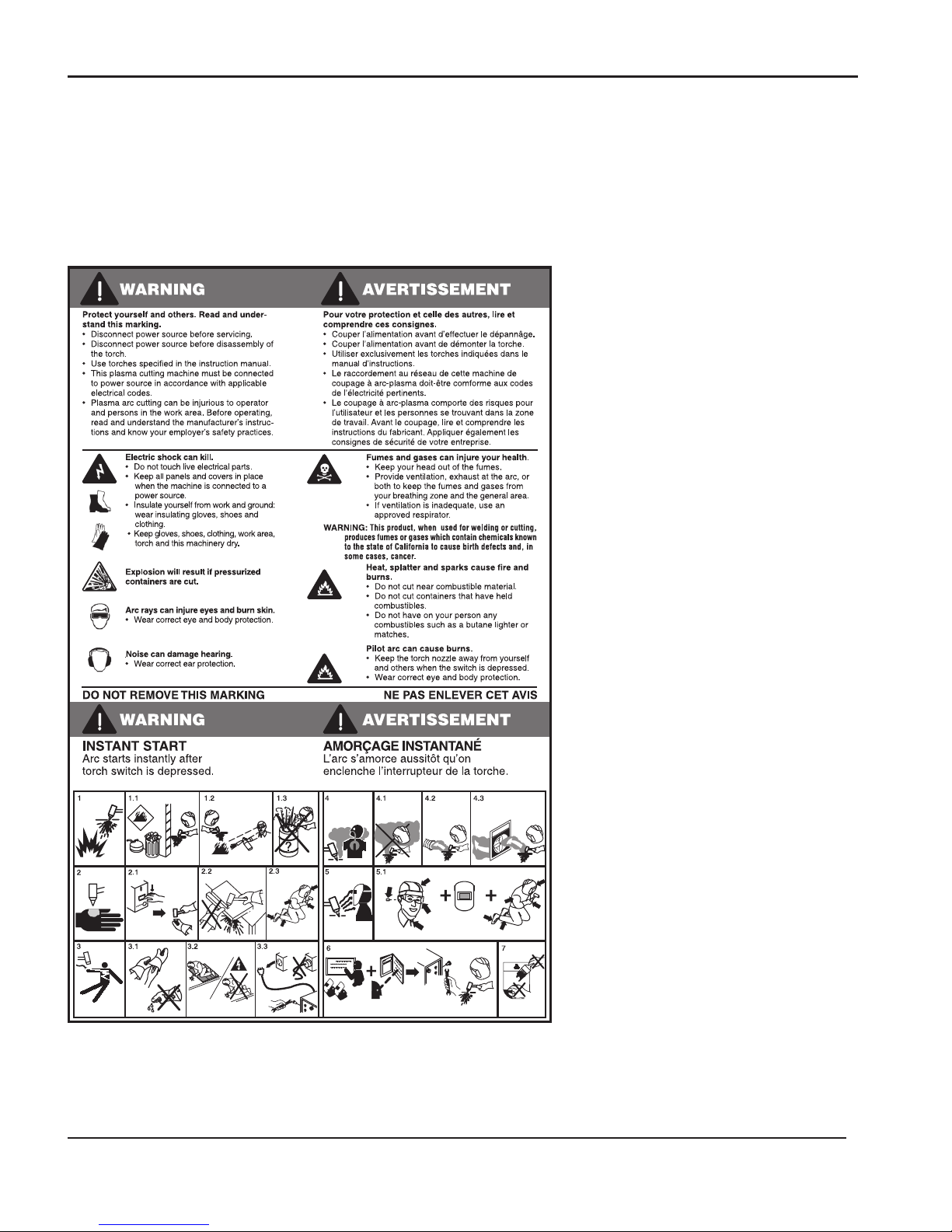
SEGURIDAD
1b-8 Hypertherm Sistemas plasma
Etiqueta de advertencia
Esta etiqueta de advertencia se encuentra adherida a la fuente de
energía. Es importante que el operador y el técnico de mantenimiento
comprendan el sentido de estos símbolos de advertencia según se
describen. El texto numerado corresponde a los cuadros numerados de
la etiqueta.
1. Las chispas producidas por el corte
pueden causar explosiones o incendios.
1.1 Mantenga los materiales inflamables
lejos del lugar de corte.
1.2 Tenga a mano un extinguidor de
incendios y asegúrese de que alguien
esté preparado para utilizarlo.
1.3 No corte depósitos cerrados.
2. El arco de plasma puede causar
quemaduras y lesiones.
2.1 Apague la fuente de energía antes de
desarmar la antorcha.
2.2 No sostenga el material junto al trayecto
de corte.
2.3 Proteja su cuerpo completamente.
3. Los electrochoques provocados por la
antorcha o el cableado pueden ser
fatales. Protéjase del electrochoque.
3.1 Colóquese guantes aislantes. No utilice
guantes dañados o mojados.
3.2 Aíslese de la pieza de trabajo y de la
tierra.
3.3 Antes de trabajar en una máquina,
desconecte el enchufe de entrada o la
potencia primaria.
4. La inhalación de los humos provenientes
del área de corte puede ser nociva para
la salud.
4.1 Mantenga la cabeza fuera de los gases
tóxicos.
4.2 Utilice ventilación forzada o un sistema
local de escape para eliminar los humos.
4.3 Utilice un ventilador para eliminar los
humos.
5. Los rayos del arco pueden producir
quemaduras en los ojos y en la piel.
5.1 Utilice un sombrero y gafas de
seguridad. Utilice protección para los
oídos y abróchese el botón del cuello de
la camisa. Utilice un casco de soldar con
el filtro de sombreado adecuado. Proteja
su cuerpo completamente.
6. Antes de trabajar en la máquina o de
proceder a cortar, capacítese y lea las
instrucciones completamente.
7. No retire las etiquetas de advertencia ni
las cubra con pintura.
110391 Rev A
Page 36

1
powermax1250 Operator Manual 2-1
Section 2
SPECIFICATIONS
In this section:
Power supply ...........................................................................................................................2-2
Dimensions and weight....................................................................................................2-3
T80 Torches .............................................................................................................................2-4
Dimensions......................................................................................................................2-5
Symbols and markings.............................................................................................................2-6
S mark ............................................................................................................................2-6
CE mark...........................................................................................................................2-6
IEC symbols used............................................................................................................2-6
Page 37

Power supply
SPECIFICATIONS
1
2-2 powermax1250 Operator Manual
Rated open circuit voltage (U0) 300 VDC
OutputCharacteristic* Drooping
*Defined as a plot of output voltage
versus output current
Rated output current (I2) 25A – 80A
Hypertherm standard rated output 150 VDC
voltage (U2)
Duty cycle (X*) at 104°F (40°C) at U1– Volts AC rms X
rated conditions (U1, I1, U2, I2) 200-208 VAC 1PH 40%
230-240 VAC 1PH 50%
*X = T
on/Tbase
, 480 VAC 1PH 60%
T
on
= time, minutes 200-208 VAC 3PH 50%
T
base
= 10 minutes 230-240 VAC 3PH 60%
(See the data plate on the power supply for 380-400-415 VAC 3PH 60%
more information on duty cycle and for IEC 480 VAC 3PH 60%
ratings.) 600 VAC 3PH 60%
Operating temperature 14oto 104oF (-10oto 40oC)
Rated AC phases (PH) and line frequency (Hz) PH Hz
Standard model 1-3 50-60
CE model 3 50-60
Rated input voltage (U1), rated input U1– Volts AC rms I1-Amps rms I1eff
current (I1) and I1eff* at rated output 200-208 VAC 1PH 70 44
U2and I2– cutting only. 230-240 VAC 1PH 60 42
480 VAC 1PH 30 23
200-208 VAC 3PH 40 28
*I1eff = (I1) X used to determine 230-240 VAC 3PH 36 28
rating of power cord. 380-400-415 VAC 3PH 21 16
480 VAC 3PH 17 13
600 VAC 3PH 16.5 13
Power factor U1– Volts AC rms Harmonic power factor Displacement
power factor
200-208 VAC 1PH 0.99 0.99
230-240 VAC 1PH 0.99 0.99
480 VAC 1PH 0.91 0.99
200-208 VAC 3PH 0.94 0.99
230-240 VAC 3PH 0.94 0.99
380-400-415 VAC 3PH 0.94 0.99
480 VAC 3PH 0.94 0.99
600 VAC 3PH 0.80 0.99
R
sce
– short circuit ratio—CE model only U1– Volts AC rms, 3PH R
sce
400 VAC 228
230 VAC 163
This equipment conforms to IEC 61000-3-12,
provided that R
sce min
= 228 at 400VAC 3PH and
163 at 230 VAC 3PH.
IP code—degree of protection IP23CS*
provided by enclosure IP– “International Protection”
2 – No ingress foreign objects
>
=12.5mm (0.5 in)
3 – No harmful ingress spraying water
C – AC line circuits protected against ingress of
tool
>
=2.5 mm dia. x 100 mm long
(0.1 inch x 4.0 inch)
S – fan stationary during water test
*
WARNING: DO NOT OPERATE IN RAIN
Toppling, tilting (with or without wheel kit) Up to 15o incline
.
Gas type Air Nitrogen
Gas quality Clean, moisture-free, oil-free
Gas inlet pressure and flow See
Section 3, Setup
Page 38
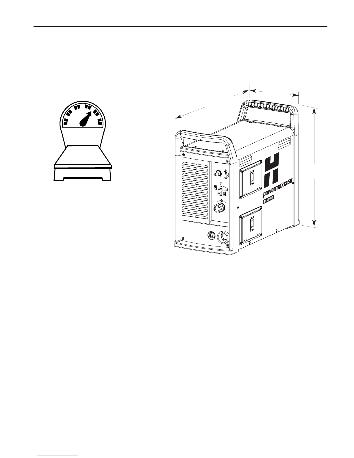
SPECIFICATIONS
0
powermax1250 Operator Manual 2-3
6
.0
B
A
R
5
.0
4
.0
P
S
I
8
0
7
05
0
6
0
60
40
A
M
P
S
80
25
A
C
+
_
Dimensions and weight
Weight of the power supply
without a torch
90 lb
(41 kg)
23 in
(584 mm)
10.5 in
(267 mm)
19.5 in
(495 mm)
Page 39

SPECIFICATIONS
1
2-4 powermax1250 Operator Manual
Handheld cutting capacity at 80 amps
Recommended capacity 7/8 inch (22 mm)
Maximum capacity 1-1/8 inch (29 mm)
Severance capacity 1-1/2 inch (38 mm)
Mechanized cutting capacity at 80 amps
Recommended capacity 3/8 inch (10 mm)
Maximum capacity 5/8 inch (16 mm)
Gouging Capability
12.2 pounds (5.5 kg) hour
(metal removal rate on mild steel)
Weight
7.2 pounds (3.3 kg) with 25 ft (7.5 m) lead
T80 13.9 pounds (6.3 kg) with 50 ft (15 m) lead
20.6 pounds (9.4 kg) wih 75 ft (22.5 m) lead
4.5 pounds (2.0 kg) with 15 ft (4.5 m) lead
8.3 pounds (3.8 kg) with 25 ft (7.5 m) lead
T80M 9.9 pounds (4.5 kg) with 35 ft (10.7 m) lead
15.0 pounds (6.8 kg) with 50 ft (15 m) lead
21.7 pounds (9.9 kg) with 75 ft (22.5 m) lead
T80 torches
Page 40
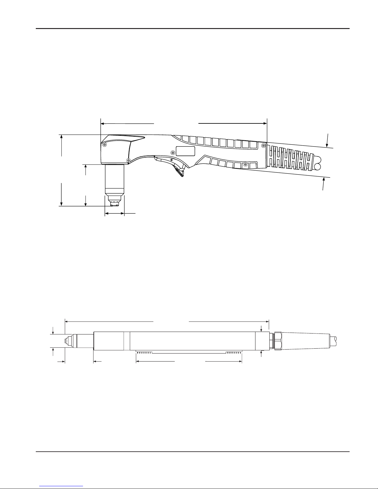
SPECIFICATIONS
1
powermax1250 Operator Manual 2-5
T80 dimensions
8.9" (226 mm)
3.9"
(99 mm)
1.5"
(38 mm)
1.00"
(25 mm)
2.25"
(57 mm)
Torch dimensions
15.25"
(387 mm)
1.00"
(25 mm)
1.38"
(35 mm)
2.03"
(52mm)
8"
(203 mm)
32 pitch 0.125" (3.2 mm) width
0.125" (3.2 mm) height
T80M dimensions
Page 41
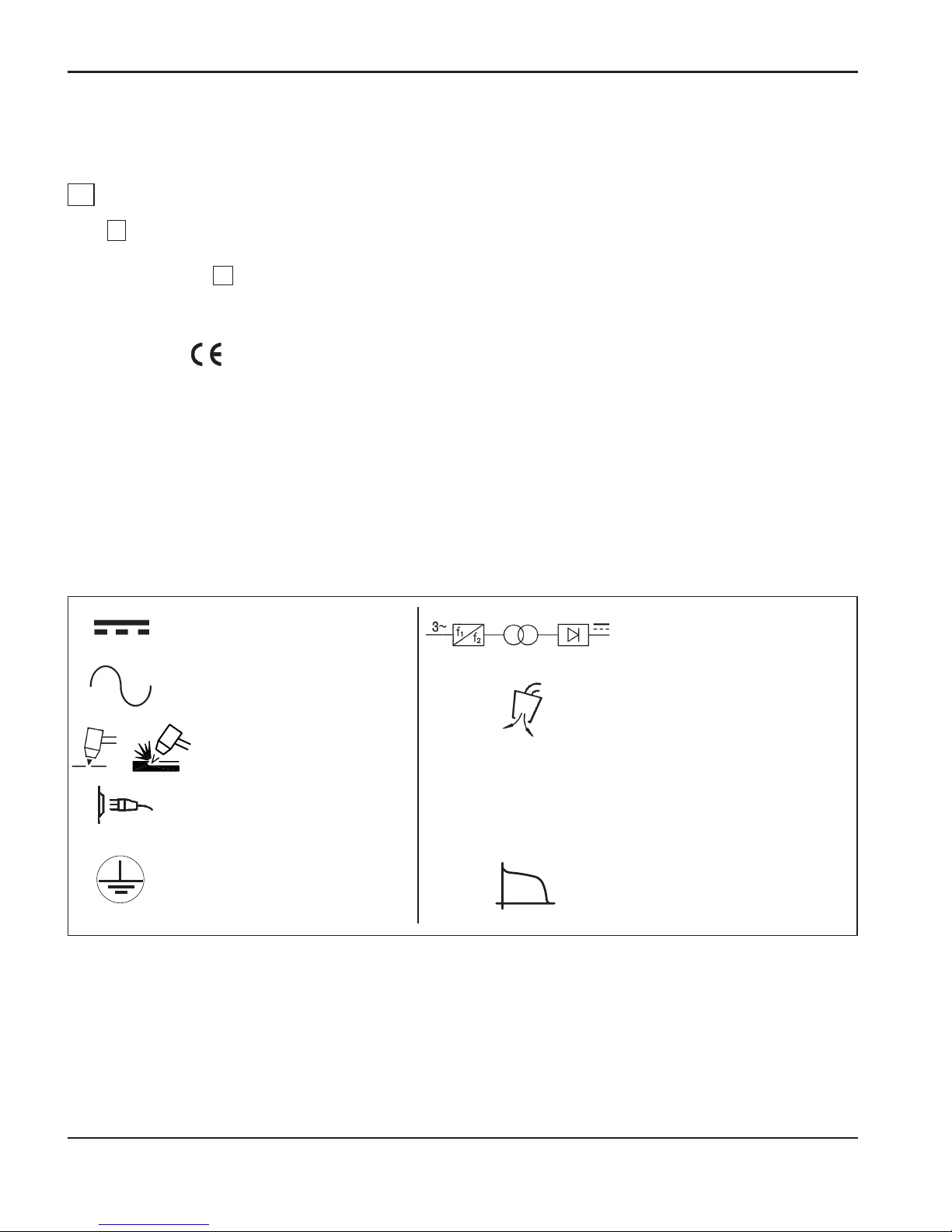
SPECIFICATIONS
1
2-6 powermax1250 Operator Manual
Symbols and Markings
S mark
The S mark indicates that the power supply and torch are suitable for use in environments
with increased hazard of electrical shock. The hand torches must have shielded consumable
parts to maintain S mark compliance.
CE mark
The CE mark ( ) constitutes a manufacturer’s declaration of conformity to applicable
European directives and standards. Only those versions of Hypertherm products with a CE
mark located on or near the data plate have been tested for compliance with the European
Low Voltage Directive and the European EMC Directive. EMC filters needed to comply with the
European EMC Directive are incorporated within versions of the power supply with a CE mark.
IEC symbols used
The following symbols may appear on the power supply data plate, control labels and
switches.
O
l
Direct Current (DC)
The terminal for the
external protective
(earth) conductor
AC input power
connection
Plasma torch cutting
and gouging
Alternating current (AC)
An inverter-based power
source
Volt/amp curve, "drooping"
characteristic
Power is off
Power is on
Plasma torch in the TEST
position (cooling and cutting
gas exiting nozzle)
Page 42

1
powermax1250 Operator Manual 3-1
Section 3
SETUP
I
n this section:
Upon receipt.............................................................................................................................3-2
Claims ......................................................................................................................................3-2
Contents of box ........................................................................................................................3-2
Locating the power supply........................................................................................................3-3
Lifting the power supply............................................................................................................3-3
Power connection.....................................................................................................................3-4
Three-phase power cord – plug installation .............................................................................3-4
Single-phase power cord..........................................................................................................3-5
Power cord installation.....................................................................................................3-5
Plug installation................................................................................................................3-5
Grounding ................................................................................................................................3-6
Extension cords........................................................................................................................3-6
Torch installation.......................................................................................................................3-7
Plasma gas supply ..................................................................................................................3-9
Additional gas filtration.....................................................................................................3-9
Gas supply installation ...........................................................................................................3-10
T80M torch alignment.............................................................................................................3-10
ON/OFF pendant connection.........................................................................................3-11
Machine interface connection ........................................................................................3-11
Arc voltage.....................................................................................................................3-12
Changing XFER (start machine motion) from dry contact closure to voltage signal......3-14
Driving an industrial isolated input module....................................................................3-15
Driving a relay coil with an external power source.........................................................3-16
Driving an industrial isolated input module with an external power source ...................3-17
Page 43
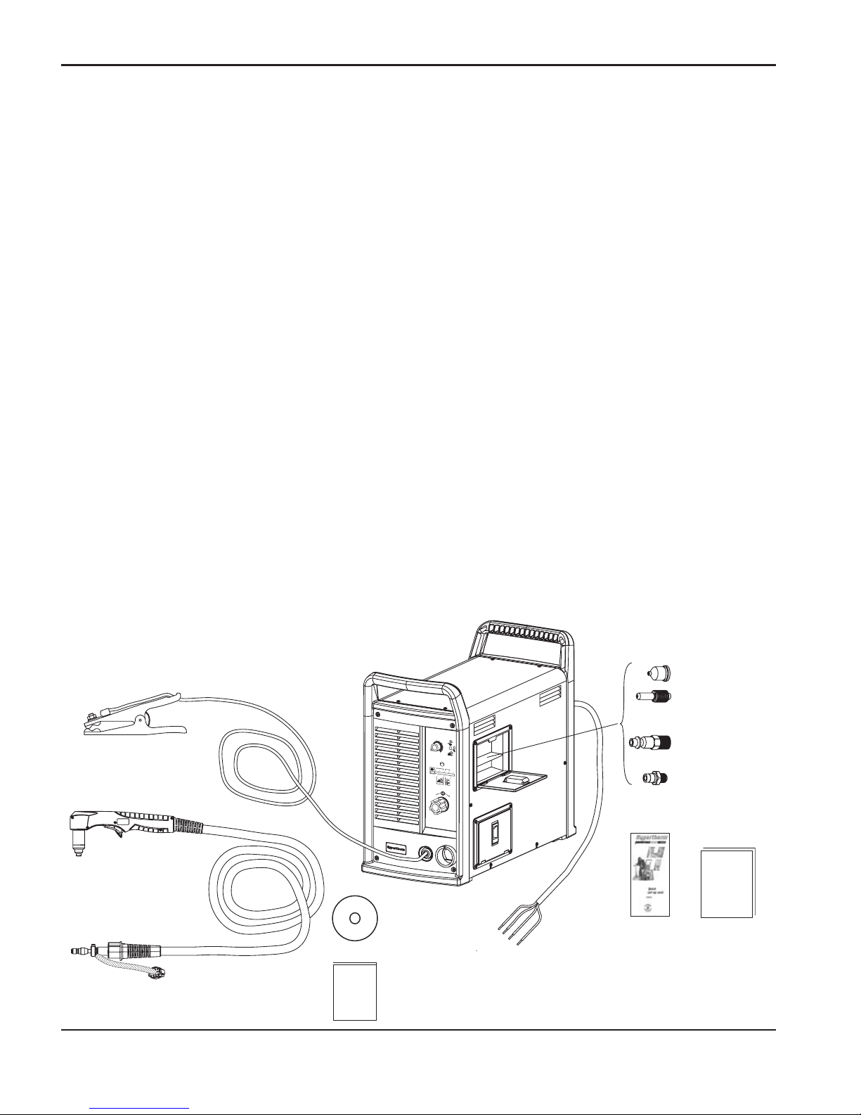
SETUP
1
3-2 powermax1250 Operator Manual
Upon receipt
1. Check that all items on your order have been received. Contact your distributor or OEM if
any items are missing or damaged.
2. If there is evidence of damage, refer to
Claims
, below. All communications regarding this
equipment must include the model number and serial number located on the back of the
power supply.
3. Read Section 1,
Safety,
before setting up and operating this Hypertherm system.
Claims
Claims for damage during shipment: If your unit was damaged during shipment, you must file a
claim with the carrier. Hypertherm will furnish you with a copy of the bill of lading upon request.
If you need additional assistance, call the nearest Hypertherm office listed in the front of this
manual.
Claims for defective or missing merchandise: If any component is missing or defective, contact
your Hypertherm distributor/OEM. If you need additional assistance, call the nearest
Hypertherm office listed in the front of this manual.
Contents of box
Verify items against the illustration shown (for hand system configurations).
6.0
BAR
5
.0
4
.0
PSI
80
7050 60
60
40
AMPS
80
25
A
C
+
_
Operator
Manual
X3
X3
X1 (Standard)
X1 (CE Model)
OR
Quick
Setup
Card
Setup CD-ROM
Warranty card
Page 44
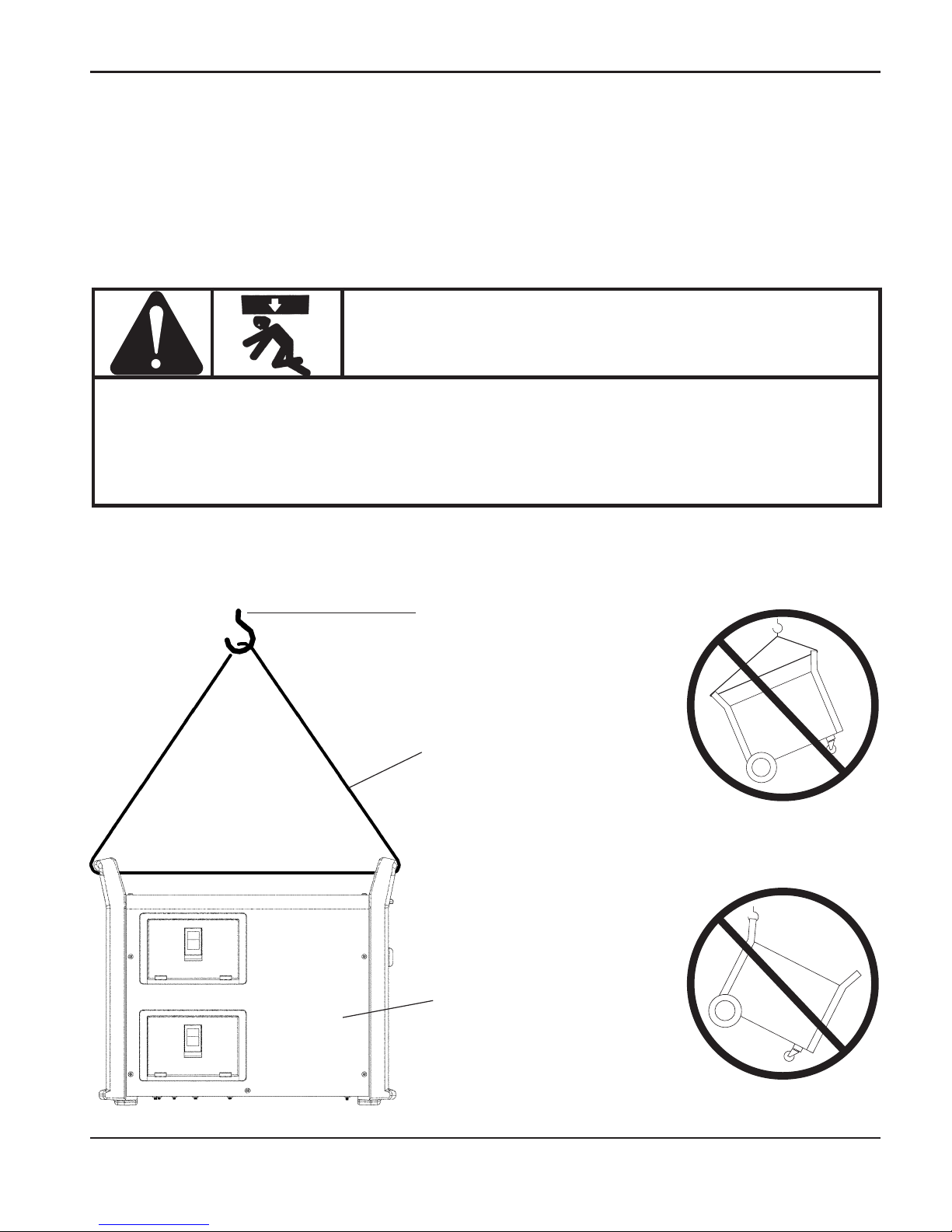
SETUP
1
powermax1250 Operator Manual 3-3
Locating the power supply
Locate the Powermax1250 power supply with at least 10 inches (0.25 m) of open space at the
front and back and fan side of the power supply for proper ventilation.
Hoist
Cover in place
Approved hoisting strap.
Keep as vertical as
possible
Lifting the power supply
WARNING
• The system weighs up to 112 lb / 51 kg.
• Always lift the power supply by TWO handles.
• Do not lift the power supply by ONE handle.
• The handle can break, resulting in injury and damage.
Page 45

SETUP
0
3-4 powermax1250 Operator Manual
Standard Model
Input Voltage
200-208 230-240 480 200-208 230-240 400 480 600
Input Current at 12kw Output
70 60 30 40 36 21 17 16.5
Input Current during Arc
Stretch
10096485656342827
Single Phase
Three Phase
CE Model
Input Voltage
230 400
Input Current at 12kw Output
36 21
Input Current during Arc
Stretch
56 34
Three Phase
Power connection
The Powermax1250 is a universal power supply that can configure itself to operate with AC
voltages from 200 to 600 (230-400 3PH for CE model). Use a line disconnect switch for each
power supply so that the operator can turn off the power supply quickly in an emergency.
Locate the switch so it is easily accessible to the operator. The interrupt level of the switch
must be equal to or exceed the continuous rating of the fuses. Use slow-blow fuses rated per
local and national electrical codes.
Three-phase power cord – plug installation
The Powermax1250 power supplies are shipped with an 8 AWG 4-wire power cord on
standard models. A6 mm2, 4-wire HAR power cord is provided on CE models. To operate the
Powermax1250, use a plug that meets national or local electrical codes. The plug must be
connected to the power cord by a licensed electrician.
Page 46
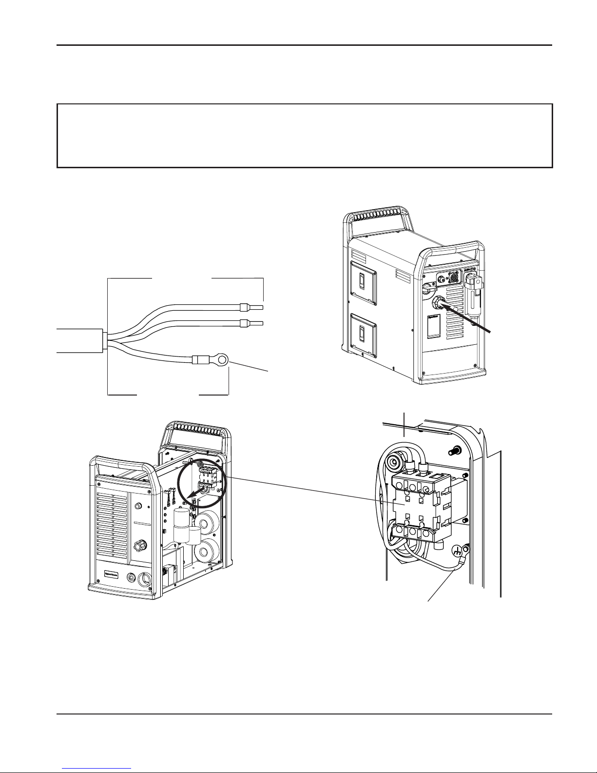
SETUP
0
powermax1250 Operator Manual 3-5
CAUTION: When using the standard model power supply (CE model is 3PH only)
with a single-phase power source, replace the supplied power cord
with a 6 AWG (16mm2) 3-wire power cord. The power cord must be
connected by a licensed electrician.
Single-phase power cord (not for CE model)
Power cord installation
Strip and prepare the power cord wires as
shown below:
Plug installation
The plug must be connected to the power cord by a licensed electrician.
L1
#10
Ground
L2
4” (102 mm)
7” (178 mm)
Route lead
through
strain relief
and tighten.
Power Switch
Ground
L1 & L2
Page 47

SETUP
0
3-6 powermax1250 Operator Manual
Grounding
To ensure personal safety and proper operation, and to reduce electromagnetic interference
(EMI), the Powermax1250 must be properly grounded through the power cord according to
national or local electrical codes. Three-phase service must be of the 4-wire type with a green
or green/yellow wire for protective earth ground and must comply with national or local
electrical requirements. Single-phase service must be of the 3-wire type with a green or
green/yellow wire for protective earth ground and must comply with national or local electrical
requirements. Refer to Section 1,
Grounding safety
.
Extension Cords
Use a cord that is certified by national or local codes. The cord should be installed by a
licensed electrician. Refer to the length requirements listed below.
Recommended extension cord gauge size AWG (mm2)
< 10 ft 10-25 ft 25-50 ft 50-100 ft 100-150 ft
< 3 m 3 – 7.5 m 7.5 – 15 m 15 – 30 m 30 – 45 m
Standard model
Input-
voltage Phase AWG mm
2
AWG mm2AWG mm2AWG mm2AWG mm
2
200-208 VAC 1 6 (16) 6 (16) 6 (16) 4 (25) 2 (35)
230 VAC 1 6 (16) 6 (16) 6 (16) 4 (25) 2 (35)
480 VAC 1 10 (6) 10 (6) 10 (6) 8 (10) 8 (10)
200-208 VAC 3 8 (10) 8 (10) 8 (10) 6 (16) 6 (16)
230 VAC 3 8 (10) 8 (10) 8 (10) 6 (16) 6 (16)
400 VAC 3 10 (6) 10 (6) 10 (6) 10 (6) 8 (10)
480 VAC 3 10 (6) 10 (6) 10 (6) 10 (6) 8 (10)
600 VAC 3 10 (6) 10 (6) 10 (6) 10 (6) 10 (6)
CE model Phase mm
2
mm
2
mm
2
mm
2
mm
2
230 VAC 3 (6) (6) (10) (10) (10)
400 VAC 3 (6) (6) (6) (6) (10)
Page 48
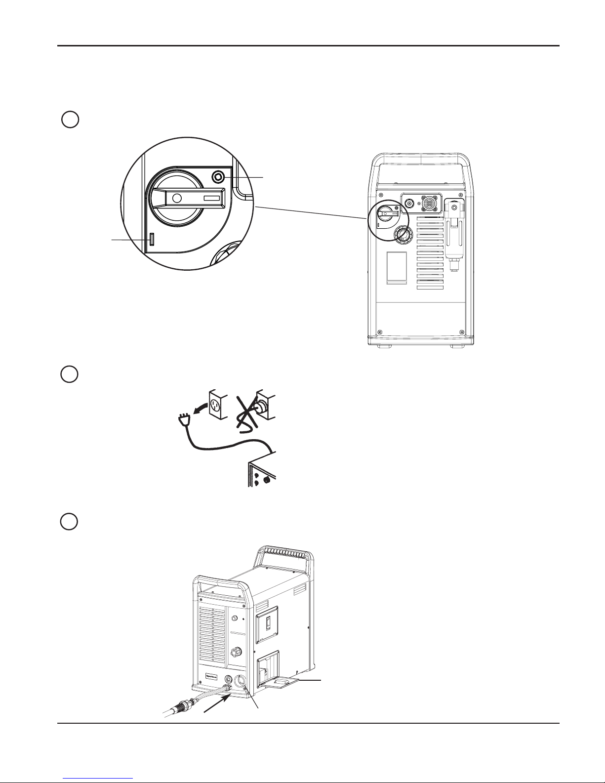
SETUP
0
powermax1250 Operator Manual 3-7
Torch installation
Turn OFF power.
Remove the power cord from the power receptacle.
Open the ETR door and route the lead through the end cap.
OFF
ON
ETR door
End cap
1
2
3
Page 49
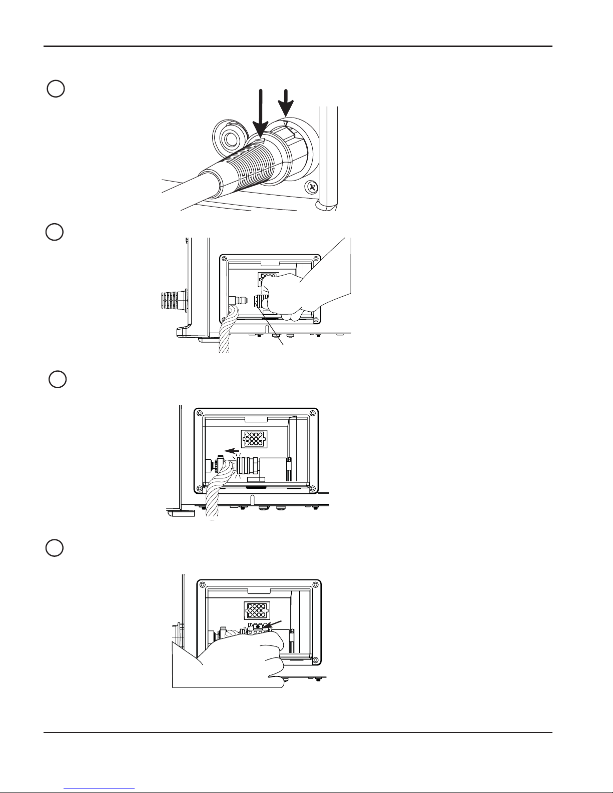
SETUP
1
3-8 powermax1250 Operator Manual
Align the marks on the strain relief.
Pull back the quick release collar and insert the lead’s gas fitting.
Slide the quick release collar foward to lock in the gas fitting. Make sure that the gas
fitting is secure.
Make sure that the red dot on the connector is on top, then plug in the electrical
connector. Close the ETR door.
Quick Release
Collar
4
5
6
7
Page 50
SETUP
1
powermax1250 Operator Manual 3-9
Plasma gas supply
The gas supply for the Powermax1250 can be shop compressed air or cylinder compressed
air.A high-pressure regulator must be used on either type of supply and must be capable of
delivering gas to the filter on the power supply at 400 scfh/6.7 scfm (189 l/min), minimum flow
rate, at a minimum pressure of 90 psig (6.1 bar). If gas supply quality is poor, cut speeds
decrease, cut quality deteriorates, cutting thickness capability decreases, and parts life
shortens.
Gas supply
Powermax1250
Water/particle filter Oil filter Oil vapor filter
Additional gas filtration
Use Hypertherm filter kit, part number 128647, when site conditions introduce moisture, oil or
other particulates into the air line. A3-stage coalescing filtration system, as shown, can also be
used.
WARNING
Do not allow the air inlet pressure to the filter on the power supply to exceed
120 psi (8.3 bar). The filter bowl may explode if this pressure is exceeded.
Page 51
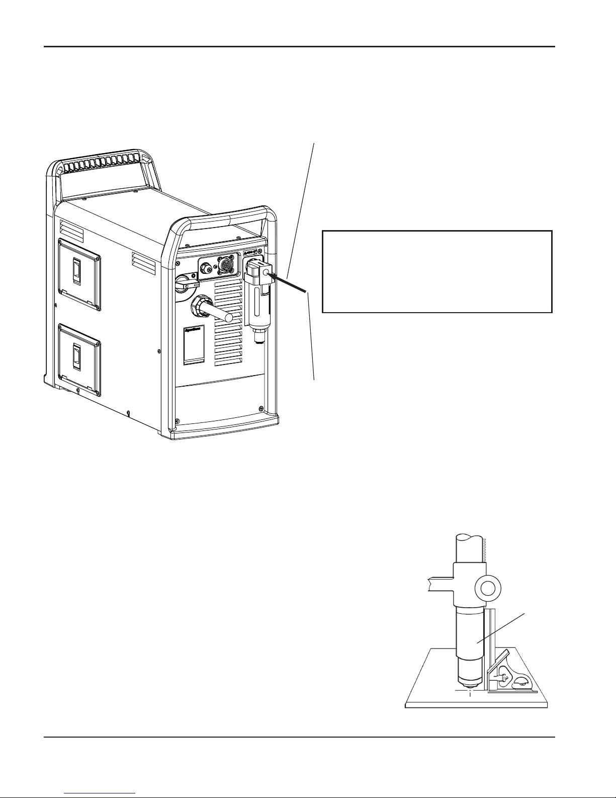
SETUP
1
3-10 powermax1250 Operator Manual
T80M torch alignment
Mount the machine torch perpendicular to the workpiece in
order to get a vertical cut. Use a square to align the torch at
0° and 90°.
Gas supply installation
Connect the air hose as follows:
1. Air fitting
• Standard model: Install a 1/4 NPT
gas fitting on the air filter inlet. CE
model: Use a G1/4 adapter (supplied).
Use liquid pipe sealant on threads.
• The nipple and adapter are in the
consumables box, located on the left
side of the power supply cover.
2. Air hose
• Use an inert gas hose with a 3/8 inch
(9.5 mm) internal diameter. Connect
it to the gas fitting installed in step 1.
Adjust the air pressure according to the
procedure in Section 4,
Operation
.
Torch
CAUTION: Never use Teflon tape
when installing the nipple or
adapters. Bits of tape can break off
and enter the air line and harm the
pressure regulator, pressure switch
and valve.
0°
90°
Page 52
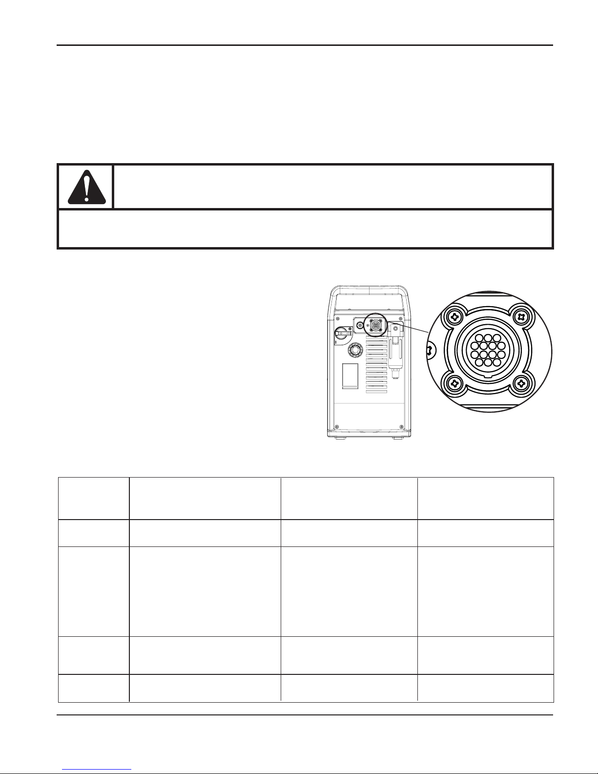
SETUP
1
powermax1250 Operator Manual 3-11
Machine interface connection
Signals for arc transfer and start are available
through the machine interface connection on
the rear of the power supply. Plug the machine
interface cable (part number 023206) into the
connector on the rear panel.
Powermax1250 power supplies sold as part of
the PowermaxEdge® package include a
machine interface cable with a voltage divider.
Refer to the following table when connecting
the machine interface cable to the cutting
machine.
Signal Start (start plasma) XFER PowermaxEdge
(start machine motion) (Interface cable with
voltage divider)
Type: Input Output Output
Notes: Normally open. 18VDC Normally open. Dry contact Divided arc signal of
open circuit voltage at closure when arc transfers. 50:1
START terminals. Requires 120VAC/1A maximum at
dry contact closure to activate. machine interface relay or
switching device (supplied
by customer).
Rear panel
3, 4 12, 14 5, 6
sockets
Cable wires Green, black Red, black Black, red
ON/OFF pendant connection
For the machine torch (T80M), inputs for arc start are available through the machine interface
connection on the rear of the power supply. Plug the Hypertherm remote pendant (see
Accessories
in Section 5,
Maintenance and parts
, for part numbers) into the connector on the
rear panel.
WARNING
The ON/OFF remote pendant will not operate when a hand torch is installed.
Page 53
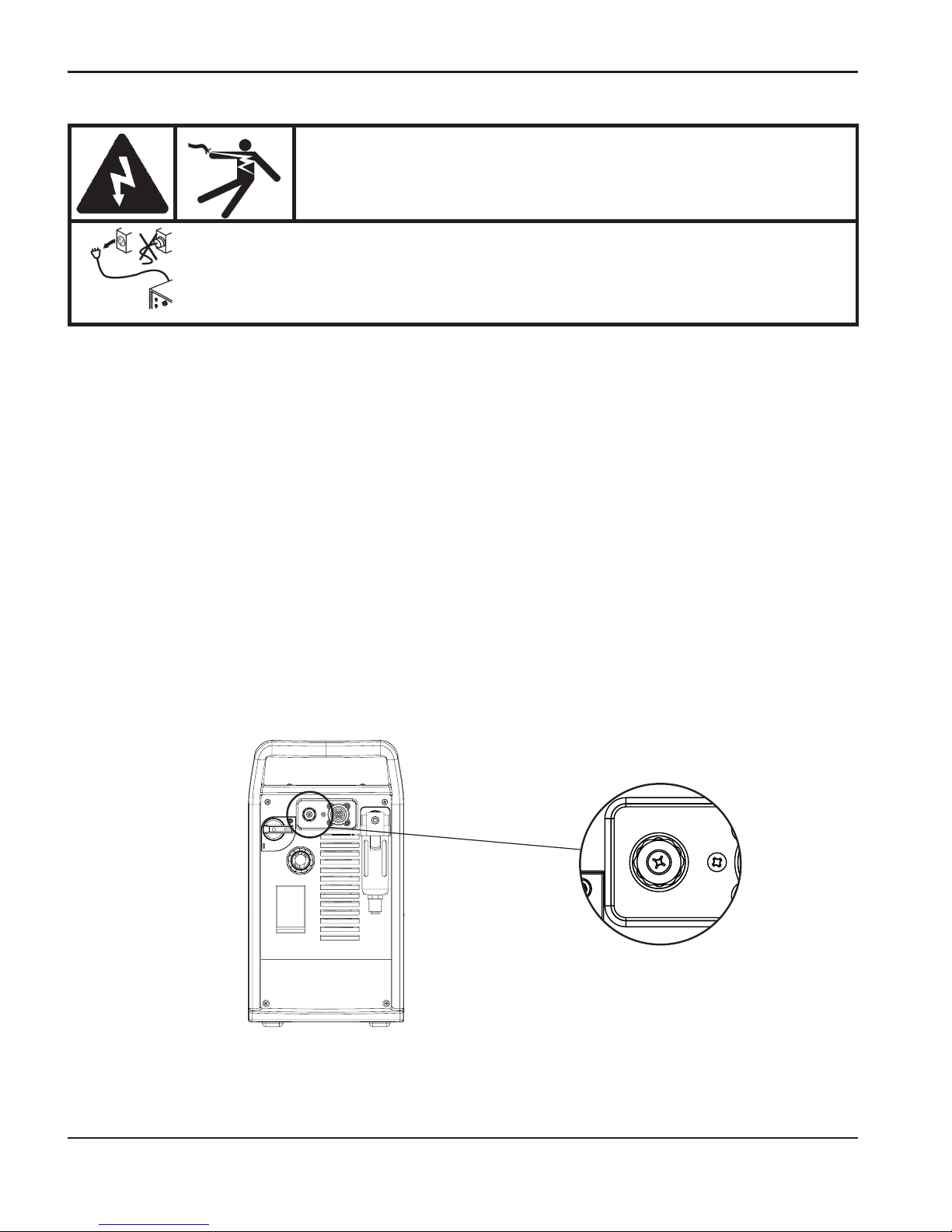
SETUP
1
3-12 powermax1250 Operator Manual
Arc voltage
For systems other than the PowermaxEdge bundle, you can use arc voltage from the power
supply to activate a torch height control. To do so, you must supply an 18 AWG (1.0 mm2),
single pair, unshielded cable rated for 300V or greater. All work must be performed following
applicable national or local codes.
1. Disconnect power from the power supply.
2. Remove screws that attach the power supply cover to the chassis. Remove the cover.
3. Feed the cable through the strain relief, shown below, at the rear of the power supply.
WARNING
ELECTRIC SHOCK CAN KILL
Disconnect electrical power before performing any maintenance.
All work requiring removal of the power supply cover must be
performed by a qualified technician.
Page 54
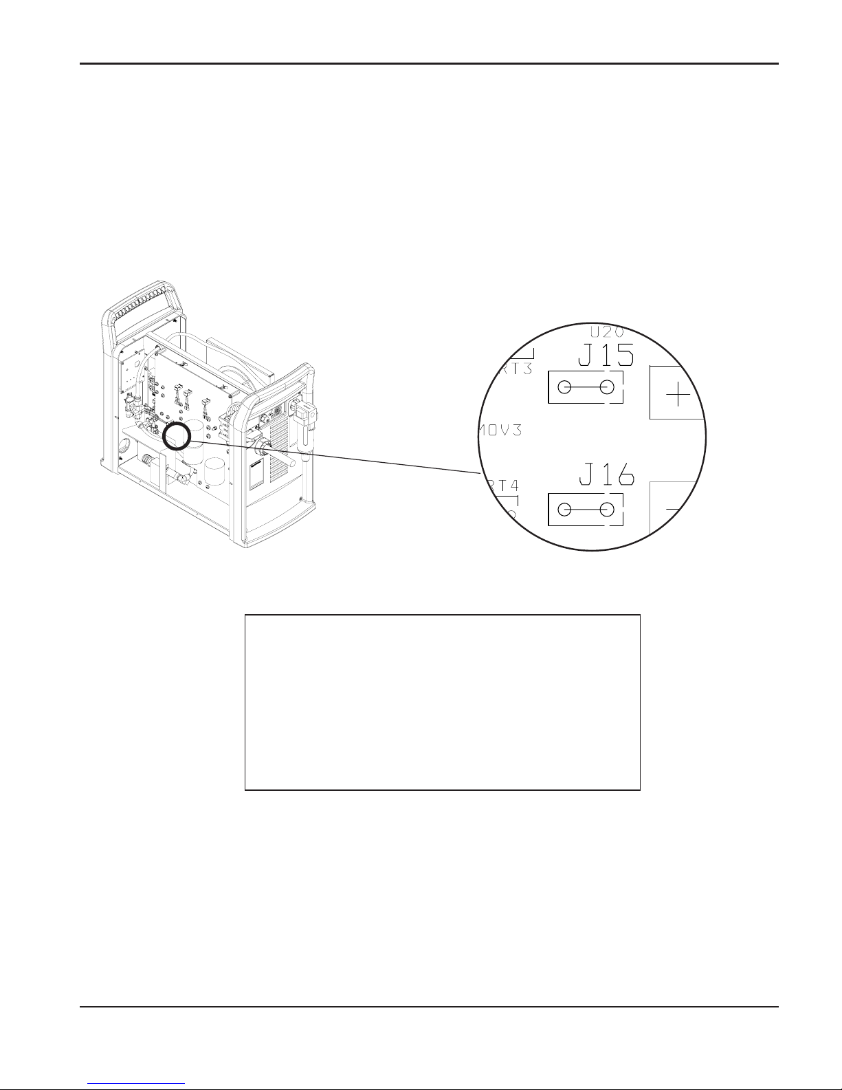
SETUP
1
powermax1250 Operator Manual 3-13
4. Find the power board, as shown below. Use insulated type 1/4" faston terminal ends to
connect to J15 and J16.
Note: 120VAC or 24 VAC must be sourced externally.
Signal: Arc voltage (torch height control)
Type: Output
Notes: Full arc voltage. No voltage divider.
300VDC maximum. (Signal not available
on rear panel connector.)
J15 +VDC
J16 -VDC
5. Tighten the strain relief.
6. Replace the cover
Page 55
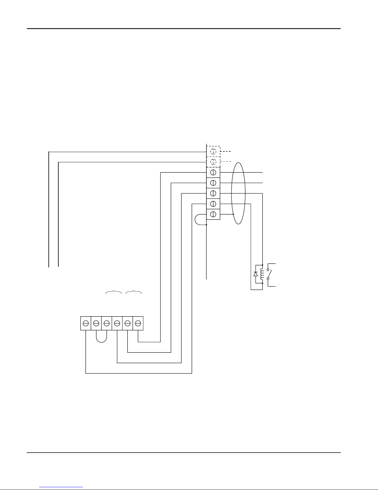
SETUP
1
3-14 powermax1250 Operator Manual
Changing XFER (start machine motion) from dry contact closure to
voltage signal
24 VDC (chassis ground reference) at 100ma max is available at J19 on the power board to
drive an isolated/floating device such as a 24 VDC relay coil (240 ohms or greater) or a typical
industrial input isolation module (which has an opto-coupler built-in). Shown below are typical
connections for a high side drive arrangement.
Driving a Relay Coil
Notes:
• Customer-supplied
24 VDC relay coil
> 240 ohms.
• Must use suppression diode
(1A, 100V) such as IN4002
through IN4004 type across
coil.
• Pins 5 and 6 are used only
on systems that include the
PowermaxEdge cable with
voltage divider.
Move black (BLK) wire to
ground (GND) and add
jumper wire as shown.
Start
Signal
Shield
13
12
14
3
4
6
5
J19
GND
24VDC
BLK
YEL
RED
WHT
V-div +
V-div -
XFER START
BLK
J16 J15
Page 56
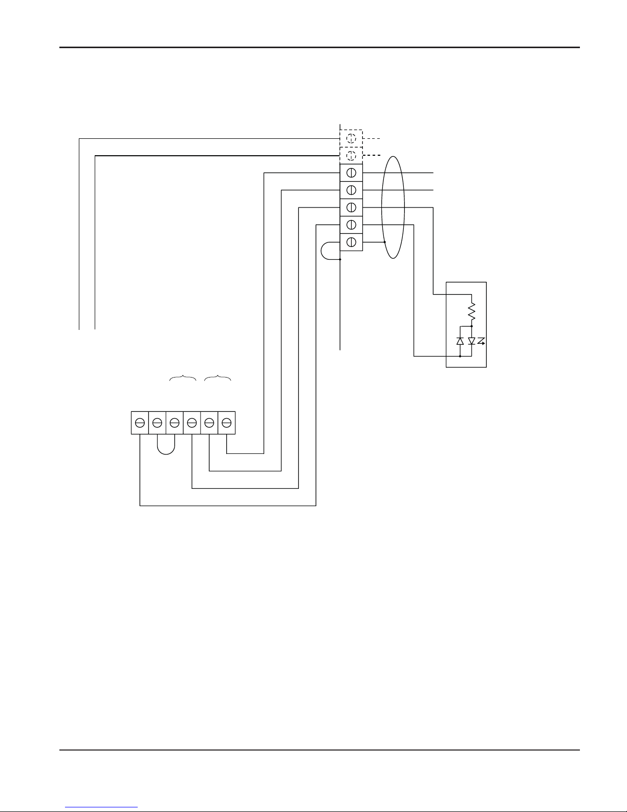
SETUP
1
powermax1250 Operator Manual 3-15
Driving an industrial isolated input module
Move black (BLK) wire to
ground (GND) and add
jumper wire as shown.
+
–
Notes:
• Customer-supplied
isolated input module.
• Pins 5 and 6 are used only
on systems that include the
PowermaxEdge cable with
voltage divider.
Start
Signal
Shield
13
12
14
3
4
6
5
V-div +
V-div -
Isolated input
module
J19
GND
24VDC
BLK
YEL
RED
WHT
XFER START
BLK
J16 J15
Page 57
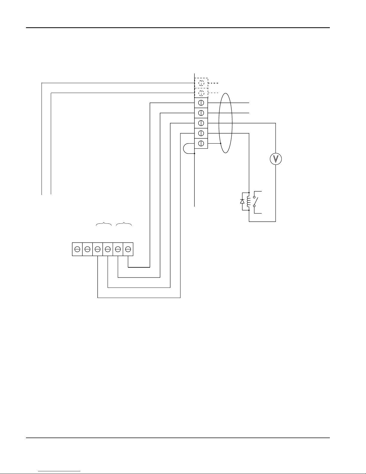
SETUP
1
3-16 powermax1250 Operator Manual
+
–
Driving a relay coil with an external power source
Notes:
• Customer-supplied 24 VDC
relay coil > 240 ohms.
• Customer-supplied 24 VDC
power source.
• Must use a suppression
diode (1A, 100V), such as
IN4002 through IN4004 type,
across the coil.
• Pins 5 and 6 are used only
on systems that include the
PowermaxEdge cable with
voltage divider.
Start
Signal
Shield
13
12
14
3
4
6
5
V-div +
V-div -
J19
GND
24VDC
BLK
YEL
RED
WHT
XFER START
24 VDC
J16 J15
Page 58
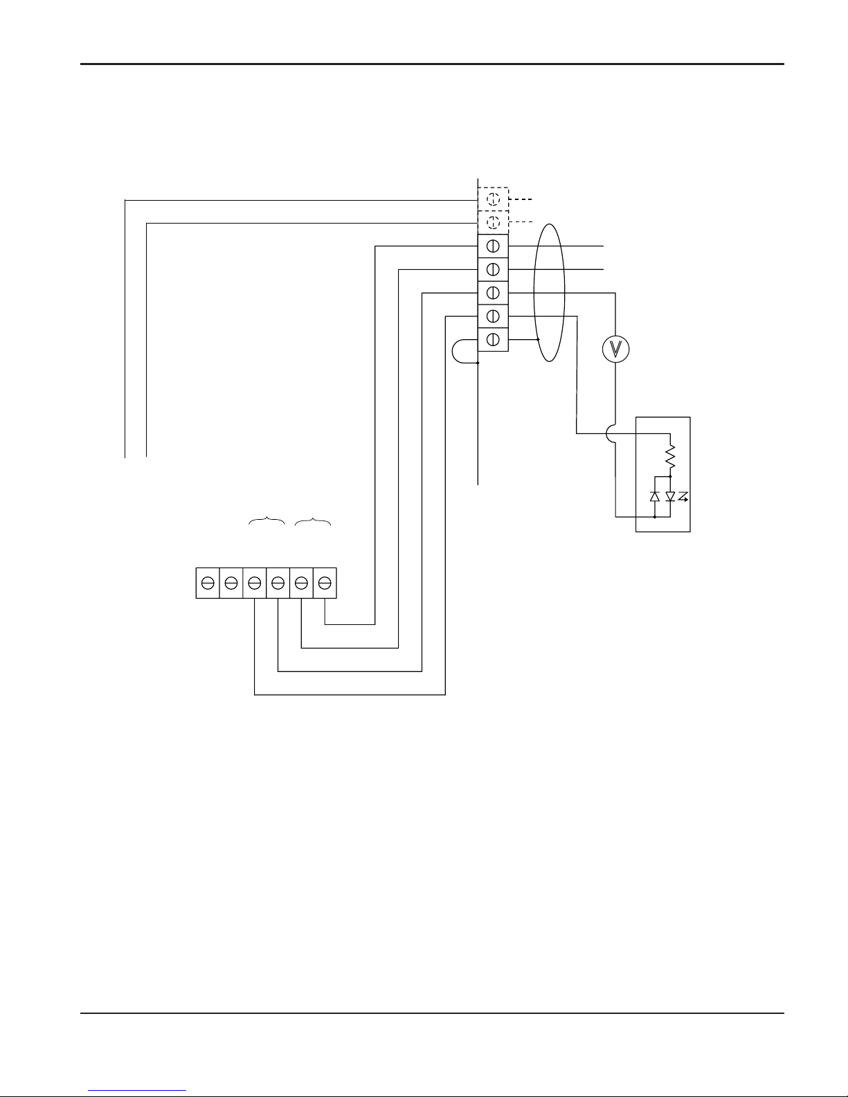
SETUP
1
powermax1250 Operator Manual 3-17
+
–
+
–
Driving an industrial isolated input module with an external power source
Notes:
• Customer-supplied
isolated input module.
• Customer-supplied
24 VDC power source.
• Pins 5 and 6 are used only on
systems that include the
PowermaxEdge cable with
voltage divider.
Start
Signal
Shield
13
12
14
3
4
6
5
V-div +
V-div -
24 VDC
Isolated input
module
J19
GND
24VDC
BLK
YEL
RED
WHT
XFER START
J16 J15
Page 59

SETUP
0
3-18 powermax1250 Operator Manual
Page 60

1
powermax1250 Operator Manual 4-1
Section 4
OPERATION
In this section:
Controls and indicators.............................................................................................................4-2
Indicator LEDs.................................................................................................................4-2
T80 consumable configurations ...............................................................................................4-3
Shielded...........................................................................................................................4-3
FineCut............................................................................................................................4-3
Gouging...........................................................................................................................4-4
T80M consumable configurations ............................................................................................4-4
Shielded...........................................................................................................................4-4
FineCut............................................................................................................................4-5
Ohmic sensing retaining cap ...........................................................................................4-5
Unshielded.......................................................................................................................4-5
Install the torch consumables...................................................................................................4-7
Set the mode switch.................................................................................................................4-8
Set the power switch to ON......................................................................................................4-8
Check the indicator lights .........................................................................................................4-8
Adjust the gas pressure and current setting.............................................................................4-9
Hand torch operation..............................................................................................................4-10
Safety trigger operation .................................................................................................4-10
Attach the work clamp....................................................................................................4-11
Starting a cut from the edge of the workpiece ...............................................................4-11
Hand torch cutting technique.........................................................................................4-12
Piercing..........................................................................................................................4-13
Gouging.........................................................................................................................4-14
Page 61

OPERATION
1
4-2 powermax1250 Operator Manual
Cut charts...............................................................................................................................4-15
80 amp mechanized shielded consumables..................................................................4-15
60 amp mechanized shielded consumables..................................................................4-16
40 amp mechanized shielded consumables..................................................................4-17
FineCut consumables....................................................................................................4-18
40 amp mechanized unsheilded consumables..............................................................4-19
Page 62
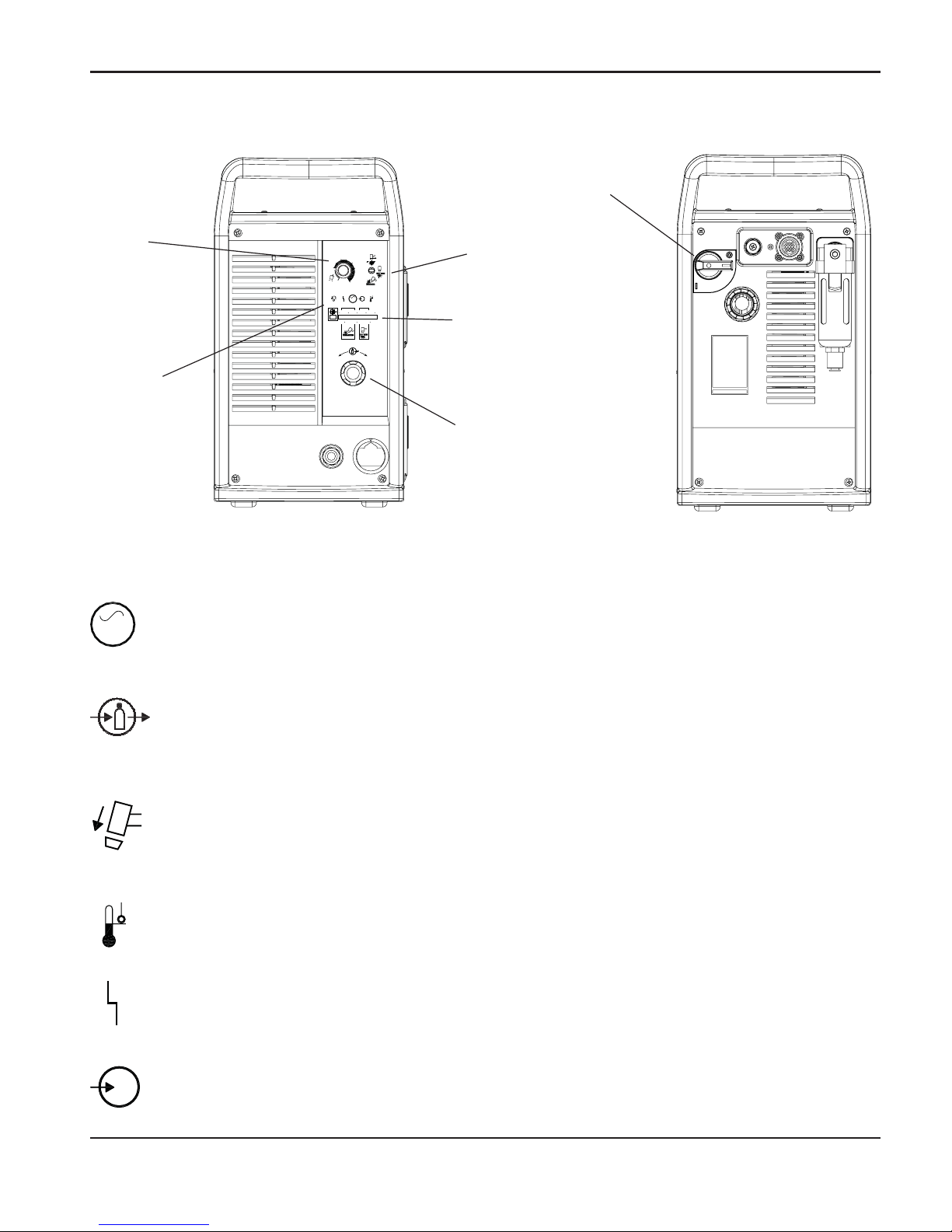
OPERATION
powermax1250 Operator Manual 4-3
1
Controls and indicators
6.0
BAR
5.04.0
PSI
807050 60
60
40
AMPS
80
25
V
AC
+
_
Current
(Amps)
adjustment
knob
Mode switch
Indicator
LEDs
Pressure
gauge
Pressure
regulator
ON (I) / OFF (0)
switch
Green power ON LED
When illuminated, indicates that power is applied to system and power switch is
ON ( I ).
Gas pressure LED
Yellow: When flashing, indicates that the gas pressure is below 60 psig (4.1 bar) for
cutting, or 40 psig (2.8 bar) for gouging.
Green: When illuminated, it indicates that there is acceptable gas pressure for torch
operation.
Yellow torch cap LED
When illuminated, indicates that the retaining cap is loose or not installed.
Note: The condition must be corrected and power turned OFF and then ON again to
clear LED.
Yellow temperature LED
When illuminated, indicates that the power supply temperature has exceeded its
operating limit.
Red fault LED
When illuminated, indicates that a fault condition exists, which prevents system
operation.
Yellow low line voltage LED
When illuminated, indicates that line voltage is below 170 VAC or above 680 VAC.
On CE units, it can also indicate a missing phase.
AC
AC
V
Indicator LEDs
Page 63
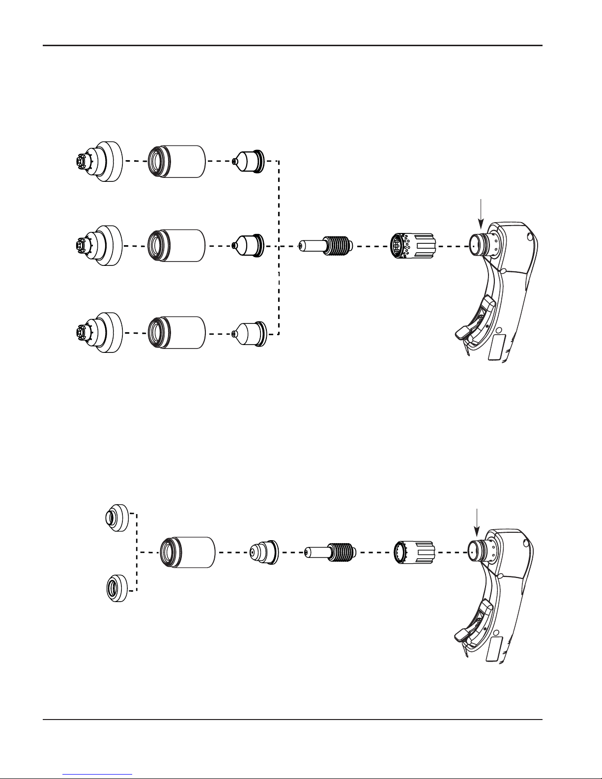
OPERATION
4-4 powermax1250 Operator Manual
1
T80 consumable configurations
120925
120926
120977 120927120928
O-ring
058519
Shielded
120929 120931120928
120929 120932120928
FineCut
O-ring
058519
220327**
120926
220329
120928
220325*
120979
*For use with CE systems.
**The 22037 swirl ring is intended for manual
cutting with FineCut consumables.
40A
60A
80A
30A — 50A
Page 64
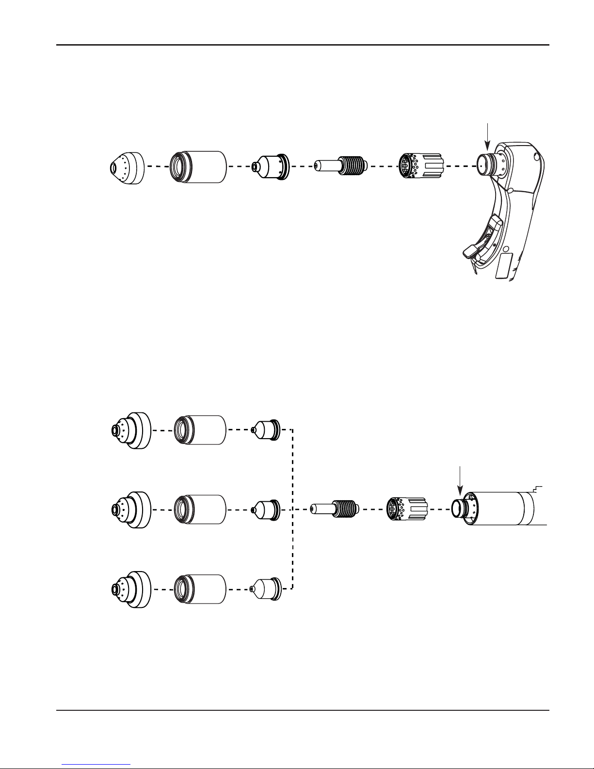
OPERATION
1
powermax1250 Operator Manual 4-5
120930 120932
120928
120930
120927
120928
120928
120925120926
O-ring
058519
Gouging
120977 220059120928
60A/80A
O-ring
058519
120926 120925
T80M consumable configurations
Shielded
120930
120931
40A
60A
80A
Page 65
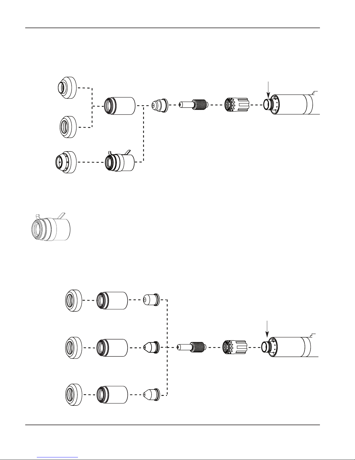
OPERATION
1
4-6 powermax1250 Operator Manual
FineCut
O-ring
058519
120925
120926
220329
120928
220325*
120979
220404
220061**
Ohmic sensing retaining cap
220061**
Unshielded*
40A
60A
80A
O-ring
058519
120979
120979
120979
120928
120928
120928
220006
220007
120980
120926 120925
*In CE countries, unshielded consumables
may only be used in mechanized torch
applications.
**Use an ohmic sensing cap when a
compatible torch height controller is
installed.
30A – 50A
Page 66
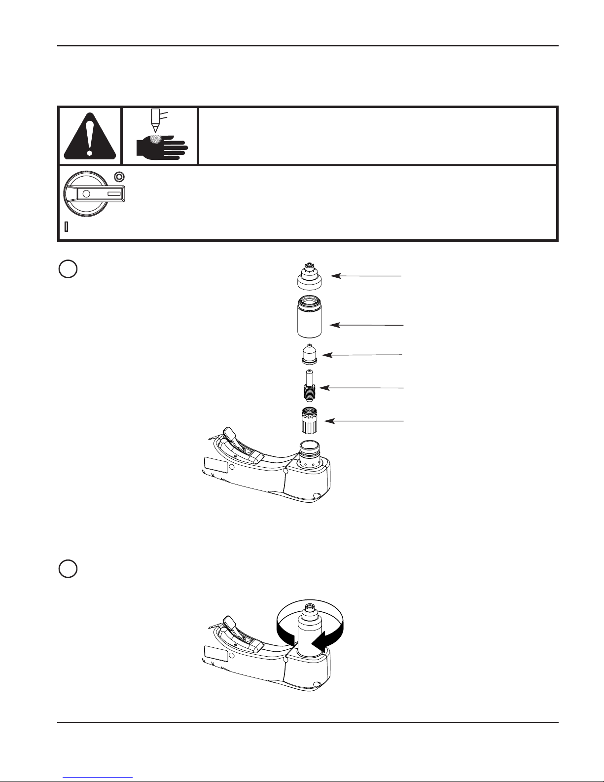
OPERATION
0
powermax1250 Operator Manual 4-7
WARNING
INSTANT-ON TORCHES
PLASMAARC CAN CAUSE INJURYAND BURNS
Plasma arc comes on immediately when the torch switch is
activated. The plasma arc will quickly burn through gloves
and skin. Make sure power is OFF before changing
consumables.
Install the torch consumables
Hand tighten only.
Retaining cap
Nozzle
Electrode
Swirl ring
Shield
1
2
Page 67
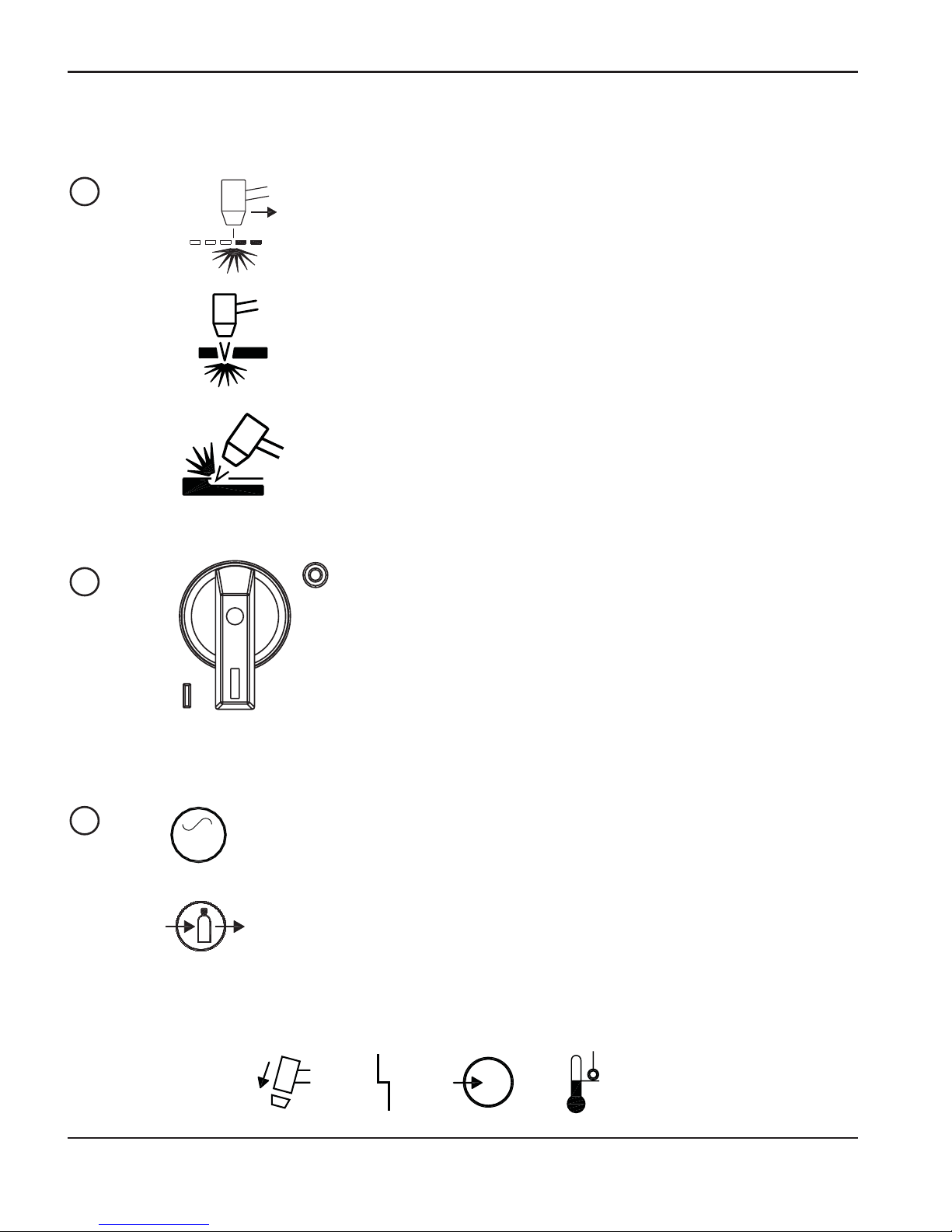
OPERATION
1
4-8 powermax1250 Operator Manual
Set the mode switch
Use to cut expanded metal.
Automatically reinitiates pilot.
Use to cut plate/sheet metal.
Optimum consumable life.
Use to gouge, or for non-transfered-arc operation.
Set the power switch to ON
Position the power switch to ON ( I ) as shown.
Check that the POWER ON lamp is illuminated.
Check the indicator lights
AC
AC
V
Check that the remaining indicator lamps are NOT illuminated. See Section 5,
Maintenance and parts
, for details.
Check that the gas pressure LED is illuminated in green.
1
2
3
Page 68
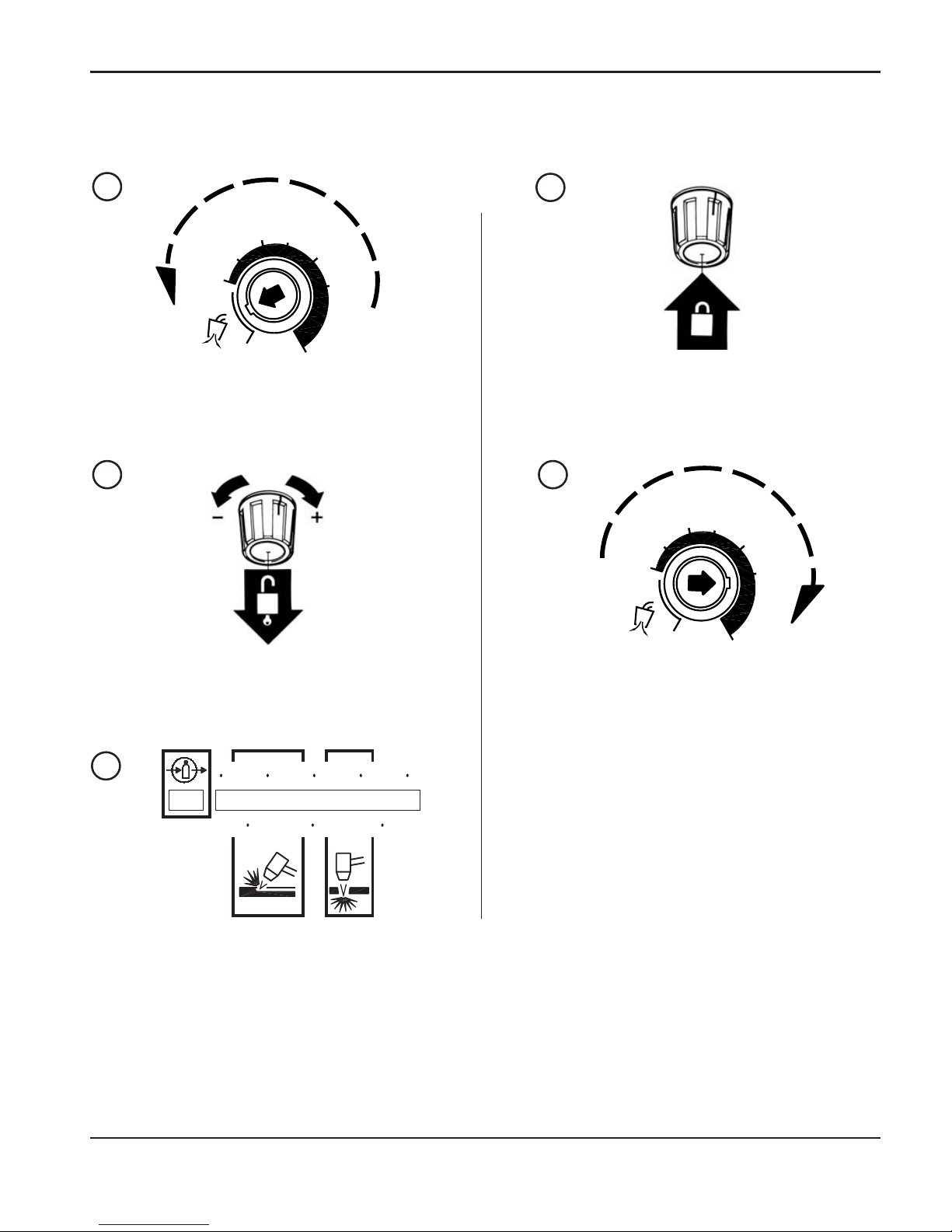
OPERATION
0
powermax1250 Operator Manual 4-9
Adjust the gas pressure and current setting
AMPS
60
40
80
25
Set the current knob to gas test.
Pull the regulator knob to unlock.
6.0
BAR
5.04.0
PSI
80
7050 60
AMPS
60
40
80
25
Set the pressure:
Cutting 70–75 psig (4.8–5.2 bar)
Gouging 50–60 psig (3.4–4.1 bar)
Push the regulator knob to lock.
Turn the current knob away from gas test to
stop the gas flow (25 amps minimum).
1
2
3
4
5
Page 69
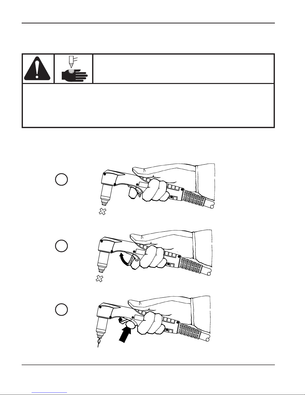
OPERATION
0
4-10 powermax1250 Operator Manual
Hand torch operation
Safety trigger operation
WARNING
INSTANT-ON TORCHES
PLASMAARC CAN CAUSE INJURYAND BURNS
Plasma arc comes on immediately when the torch switch is activated.
The plasma arc will quickly burn through gloves and skin.
• Keep away from the torch tip.
• Do not hold the workpiece, and keep your hands clear of the cutting path.
• Never point the torch toward yourself or others.
• Never use with Pendant Switch.
123
Page 70
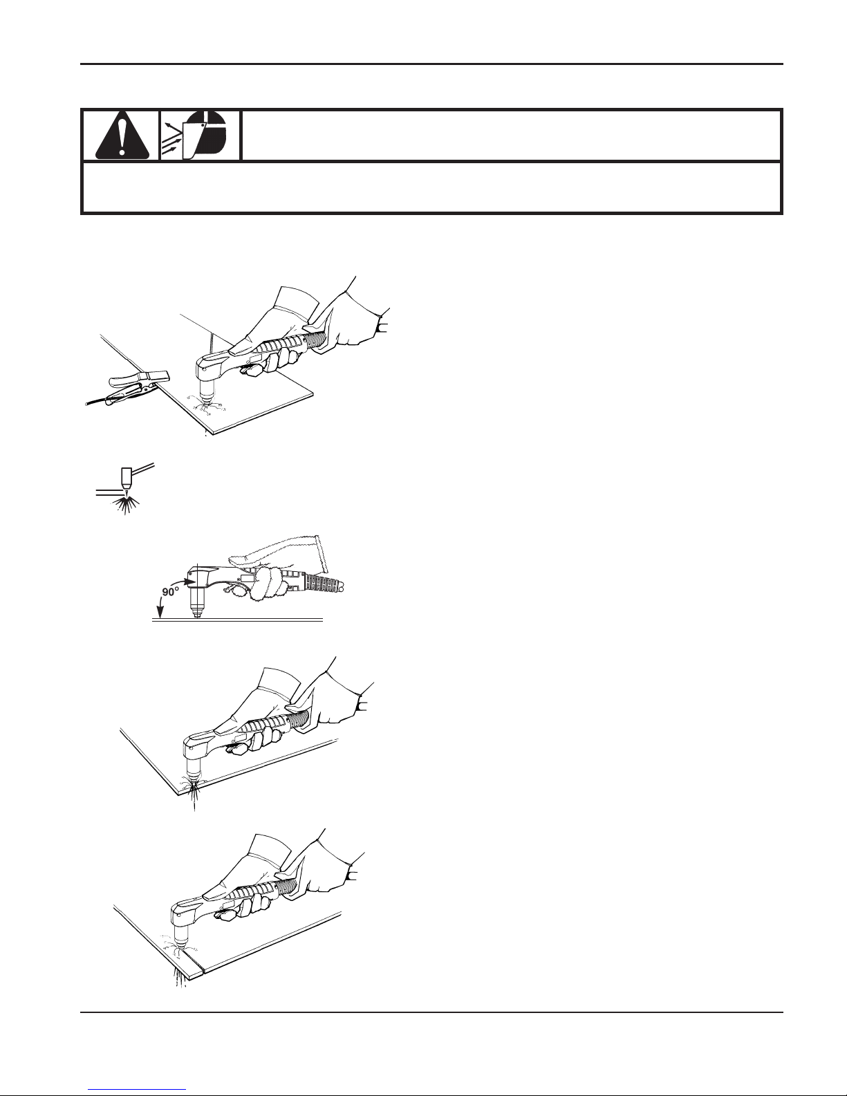
OPERATION
0
powermax1250 Operator Manual 4-11
Attach the work clamp securely to the
workpiece. Remove rust, paint or other
coatings to ensure good electrical contact.
Attach the work clamp as close as possible
to the area being cut, to reduce exposure
to electromagnetic fields (EMF).
Do not attach the work clamp to the portion
that will fall away.
Starting a cut from the edge of the workpiece
Hold the torch nozzle vertical at the edge of
the workpiece.
Start cutting from the edge of the
workpiece.
Pause at the edge until the arc has
completely cut through the workpiece.
Then, proceed with the cut.
Attach the work clamp
WARNING
SPARKS AND HOT METALCAN INJURE EYES AND BURN SKIN
When firing the torch at an angle, sparks and hot metal will spray out from
the nozzle. Point the torch away from yourself and others.
Page 71
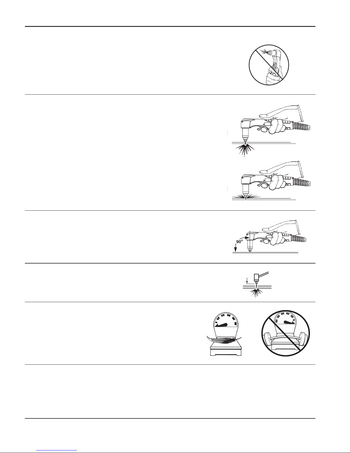
OPERATION
1
4-12 powermax1250 Operator Manual
Hand torch cutting technique
Firing the torch unnecessarily reduces nozzle and electrode life.
When cutting, make sure that sparks are exiting from
the bottom of the workpiece.
If sparks are spraying up from the workpiece, you are
moving the torch too fast, or without sufficient power.
Position the torch nozzle at a vertical position and watch
the arc as it cuts along the line.
Shielded consumables. Do not push down on the
torch when cutting. Lightly drag the torch across the
workpiece to maintain a steady cut.
• Pulling the torch through the cut is easier than pushing it.
• To cut thin material, reduce the amps until you get the best quality cut.
• For straight-line cuts, use a straight edge as a guide. To cut circles, use a template or
a Hypertherm circle cut guide, part number 027668.
Unshielded consumables. Maintain an approximate
1/8 inch (3 mm) torch-to-work distance.
Page 72
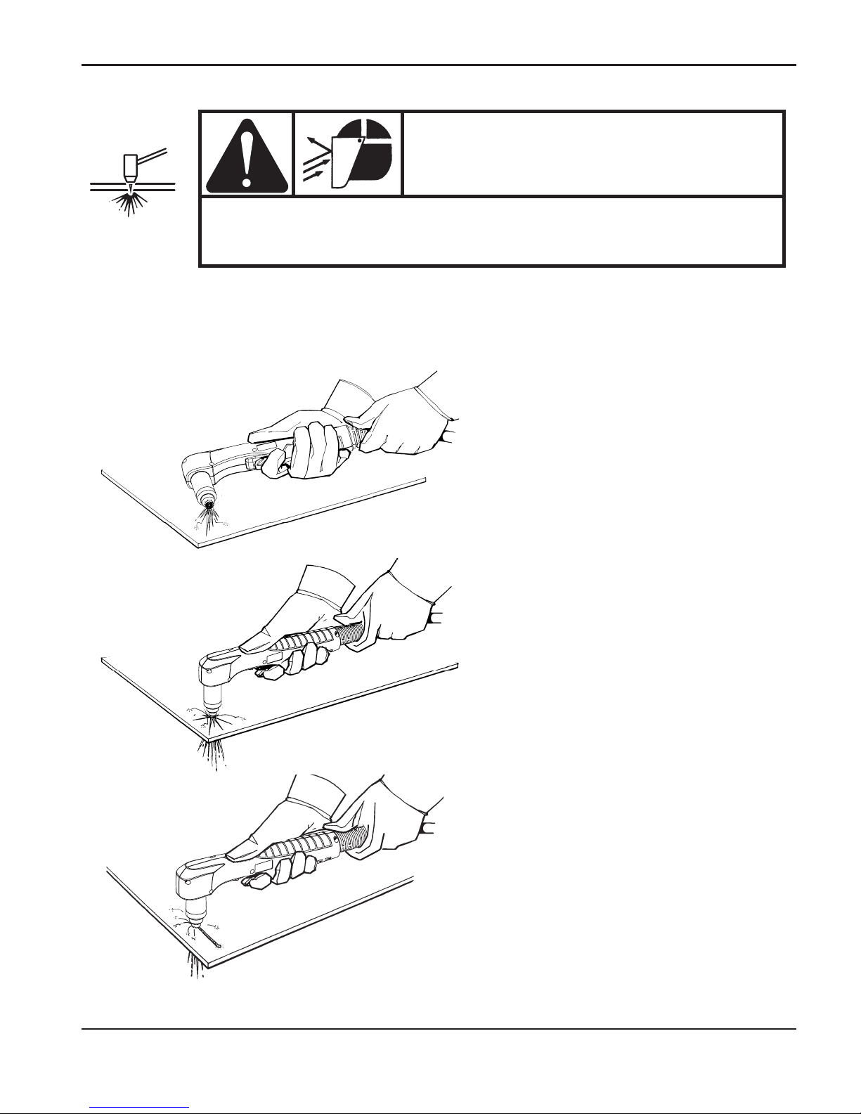
OPERATION
0
powermax1250 Operator Manual 4-13
WARNING
SPARKS AND HOT METAL CAN INJURE
EYES AND BURN SKIN
When firing the torch at an angle, sparks and hot metal will
spray out from the nozzle. Point the torch away from yourself
and others.
Piercing
Hold the torch so that the nozzle is within 1/8 inch (3 mm) from the workpiece before firing the
torch.
Fire the torch at an angle to the
workpiece, then slowly rotate it to an
upright position.
When sparks are exiting from the
bottom of the workpiece, the arc has
pierced through the material.
When the pierce is complete,
proceed with the cut.
Page 73
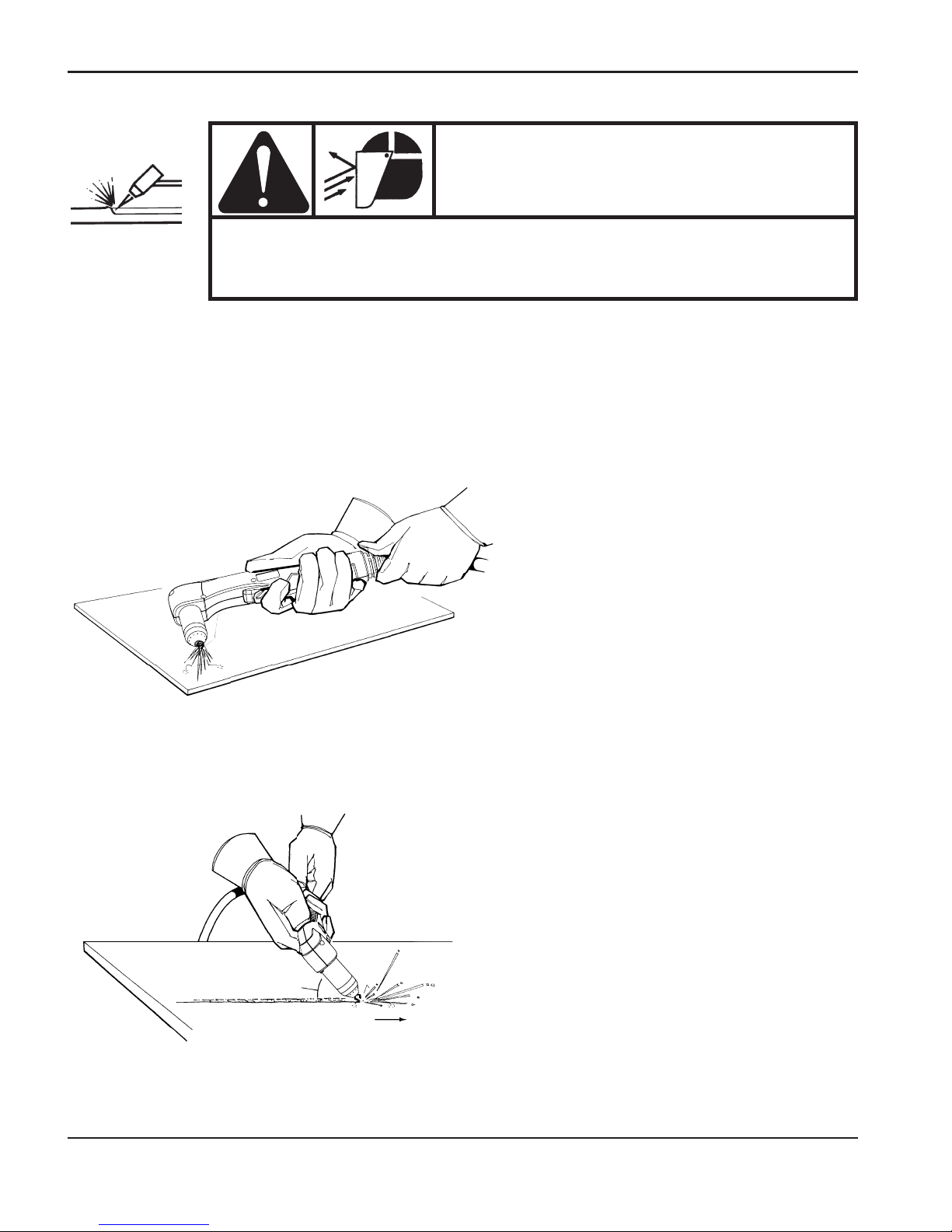
OPERATION
1
4-14 powermax1250 Operator Manual
WARNING
SPARKS AND HOT METAL CAN INJURE
EYES AND BURN SKIN
When firing the torch at an angle, sparks and hot metal will
spray out from the nozzle. Point the torch away from yourself
and others.
Gouging
Hold the torch so that the nozzle is within 1/16 inch (1.5 mm) from the workpiece before firing
the torch.
Hold the torch at a 45 degree angle
to the work piece. Pull the trigger to
obtain a pilot arc. Transfer the arc to
the work piece.
Maintain a 45° angle, approximately,
from the workpiece.
Feed into the gouge.
NOTE: Aheat shield is available for
added hand and torch protection, part
number 220049.
Direction of
travel
45°
Page 74
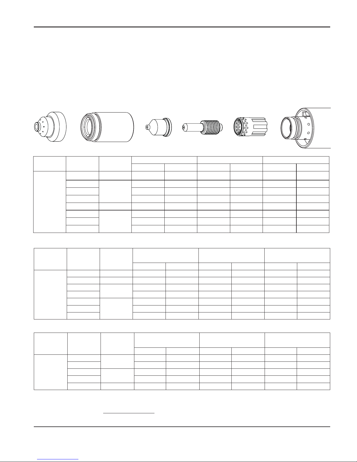
OPERATION
0
powermax1250 Operator Manual 4-15
Cut charts
80 amp mechanized shielded consumables
• Torch-to-work distance for the following cut chart is 1/16 inch (1.5 mm) for all cuts.
Retaining cap
120928
Nozzle
120927
Electrode
120926
Swirl ring
120925
T80M
torch
Shield
120930
Maximum travel speeds are the fastest travel speeds possible to cut the material without regard to cut quality.
Optimum travel speeds provide the best cut angle, least dross and best cut surface finish. Remember that cut charts
are intended to provide a good starting point for each different cut assignment. Every cutting system requires
“fine tuning” for each cutting application in order to obtain the desired cut quality.
Mild steel
Stainless steel
Aluminum
Arc
current
Arc
voltage
Pierce
delay
Material thickness
Maximum travel speeds Optimum travel speeds
inches mm
ipm mm/min ipm mm/min
80
134 0.25
3/16" 4.8
216 5486 140 3556
136 0.50
1/4" 6.4
158 4013 103 2616
139
0.75
3/8" 9.5
83 2108 54 1372
142
1/2" 12.7
50 1270 33 838
145
NA
5/8" 15.9
34 864 22 559
150
3/4" 19.0
24 610 16 406
153
1" 25.4
14 356 9 229
Arc
current
Arc
voltage
Pierce
delay
Material thickness
Maximum travel speeds Optimum travel speeds
inches mm
ipm mm/min ipm mm/min
80
134
0.25
1/8" 3.2
454 11532 295 7493
139
1/4" 6.4
176 4470 114 2896
143
0.75
3/8" 9.5
121 3073 60 1524
146
1/2" 12.7
75 1905 37 940
154 NA
3/4" 19.0
37 940 19 483
Arc current
Arc
voltage
Pierce
delay
Material thickness
Maximum travel speeds Optimum travel speeds
Inches mm
ipm mm/min ipm mm/min
80
132 0.25
3/16" 4.8
216 5486 140 3556
134
0.50
1/4" 6.4
161 4089 105 2667
137
3/8" 9.5
94 2388 61 1549
140
1/2" 12.7
60 1524 39 991
145 1.00
5/8" 15.9
40 1016 26 660
148
N/A
3/4" 19.0
31 787 20 508
150
7/8" 22.2
23 584 15 381
156
1" 25.4
16 406 10 254
Page 75
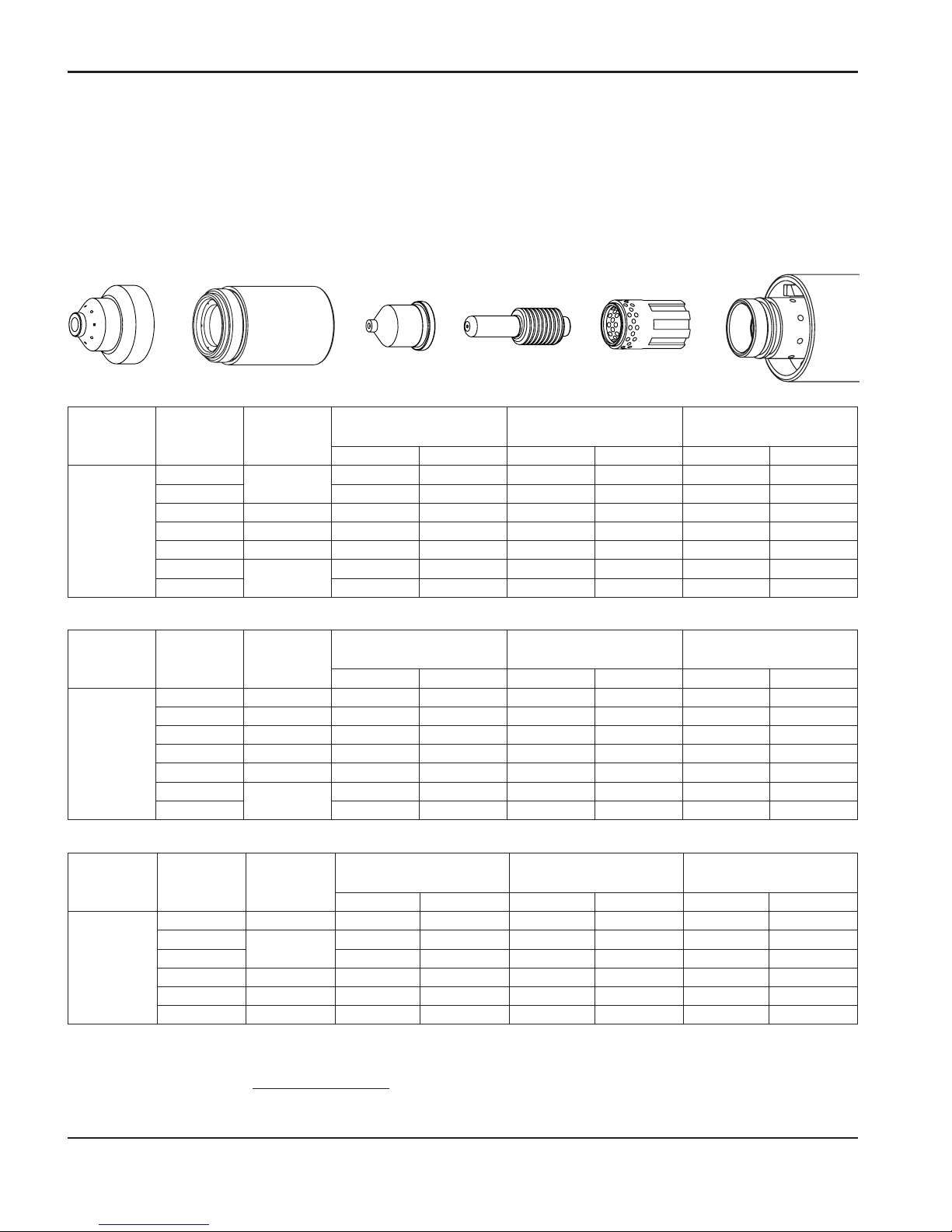
OPERATION
1
4-16 powermax1250 Operator Manual
60 amp mechanized shielded consumables
• Torch-to-work distance for the following cut chart is 1/16 inch (1.5 mm) for all cuts.
Retaining cap
120928
Nozzle
120931
Electrode
120926
Swirl ring
120925
T80M
torch
Shield
120930
Maximum travel speeds are the fastest travel speeds possible to cut the material without regard to cut quality.
Optimum travel speeds provide the best cut angle, least dross and best cut surface finish. Remember that cut charts
are intended to provide a good starting point for each different cut assignment. Every cutting system requires
“fine tuning” for each cutting application to obtain the desired cut quality.
Mild steel
Arc
current
Arc
voltage
Pierce
delay
Material thickness
Maximum travel speeds Optimum travel speeds
inches mm
ipm mm/min ipm mm/min
60
134
0
16 ga 1.5
627 15926 502 12751
134
10 ga 3.4
264 6706 211 5359
138 0.25
1/4 6.4
132 3353 86 2184
141 0.75
3/8 9.5
63 1600 41 1041
141 1.50
1/2 12.7
42 1067 27 686
147
NA
5/8 15.9
31 787 20 508
153
3/4 19.0
22 559 14 356
Stainless steel
Aluminum
Arc
current
Arc
voltage
Pierce
delay
Material thickness
Maximum travel speeds Optimum travel speeds
inches mm
ipm mm/min ipm mm/min
60
134 0
16 ga 1.5
625 15875 406 10312
136 0.25
10 ga 3.4
244 6198 159 4039
139 0.50
1/4 6.4
110 2794 72 1829
145 0.75
3/8 9.5
53 1346 34 864
146 2.00
1/2 12.7
35 889 23 584
149
NA
5/8 15.9
26 660 17 432
154
3/4 19.0
18 457 12 305
Arc
current
Arc
voltage
Pierce
delay
Material thickness
Maximum travel speeds Optimum travel speeds
inches mm
ipm mm/min ipm mm/min
60
135 0
1/16 1.6
666 16916 433 10998
138
0.25
1/8 3.2
400 10160 260 6604
141
1/4 6.4
145 3683 94 2388
146 0.75
3/8 9.5
74 1880 48 1219
149 1.50
1/2 12.7
51 1295 30 762
153 NA
5/8 15.9
33 838 21 533
Page 76
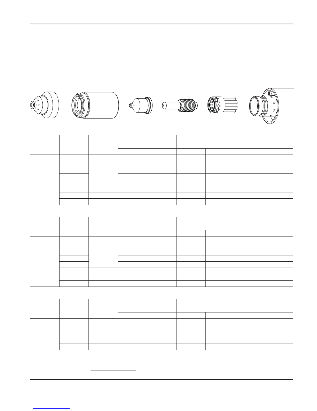
OPERATION
0
powermax1250 Operator Manual 4-17
40 amp mechanized shielded consumables
• Torch-to-work distance for the following cut chart is 1/16 inch (1.5 mm) for all cuts.
Retaining cap
120928
Nozzle
120932
Electrode
120926
Swirl ring
120925
T80M
torch
Shield
120930
Maximum travel speeds are the fastest travel speeds possible to cut the material without regard to cut quality.
Optimum travel speeds provide the best cut angle, least dross and best cut surface finish. Remember that cut charts
are intended to provide a good starting point
for each different cut assignment. Every cutting system requires
“fine tuning” for each cutting application in order to obtain the desired cut quality.
Mild steel
Arc
current
Arc
voltage
Pierce
delay
Material thickness
Maximum travel speeds Optimum travel speeds
inches mm
ipm mm/min ipm mm/min
25
147
0
26 ga 0.5
638 16205 415 10541
148
22 ga 0.8
500 12700 325 8255
149
18 ga 1.3
312 7925 203 5156
152
16 ga 1.5
176 4470 114 2896
40
144 0.25
14 ga 1.9
640 16256 221 5613
146 0.50
10 ga 3.4
151 3835 98 2489
147 0.75
3/16 4.7
97 2464 63 1600
149 1.00
1/4 6.4
74 1880 48 1219
Stainless steel
Aluminum
Arc
current
Arc
voltage
Pierce
delay
Material thickness
Maximum travel speeds Optimum travel speeds
inches mm
ipm mm/min ipm mm/min
25
139
0
26 ga 0.5
631 16027 410 10414
139
22 ga 0.8
496 12598 322 8179
40
142
0.25
18 ga 1.3
592 15037 335 8509
144
16 ga 1.5
374 9500 243 6172
144
14 ga 1.9
221 5613 144 3658
147 0.50
10 ga 3.4
107 2718 70 1778
149 0.75
3/16 4.7
67 1702 44 1118
149 1.00
1/4 6.4
47 1194 31 787
Arc
current
Arc
voltage
Pierce
delay
Material thickness
Maximum travel speeds Optimum travel speeds
inches mm
ipm mm/min ipm mm/min
25
150
0
1/32 0.8
610 15494 397 10084
152
1/16 1.5
268 6807 174 4420
40
146 0.25
3/32 2.4
293 74 42 190 4826
149 0.50
1/8 3.2
204 5182 133 3378
151 1.00
1/4 6.4
76 1930 49 1245
Page 77
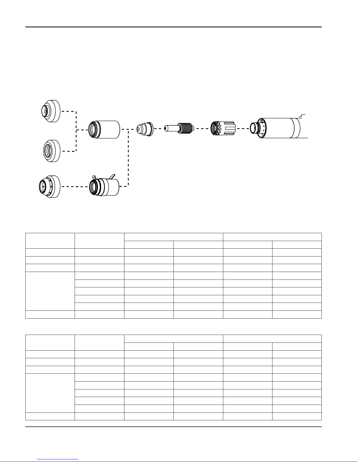
OPERATION
1
4-18 powermax1250 Operator Manual
FineCut consumables
• Torch-to-work distance for the following cut chart is 0.08 inches (2 032 mm) for mild steel and 0.010
inches (0.254 mm) for stainless steel.
* For use with CE systems.
** Use an ohmic sensing cap when a compatible
torch height controller is installed.
120925120926
220329
120928
220061**
220325*
120979
220404
Deflector Retaining
cap
Nozzle Electrode Swirl ring T80M
torch
Mild steel
Stainless steel
Arc
current
Arc
voltage
Material thickness
Approximate travel speeds
inches mm
ipm mm/min
50 76
10 ga 3.4
90 2286
40 83
10 ga 3.4
50 1270
45 77
12 ga 2.7
120 3048
40
81
12 ga 2.7
70 1778
79
14 ga 1.9
135 3810
79
16 ga 1.5
150 3810
79
18 ga 1.2
150 2540
78
20 ga 0.9
120 2540
30 80
24 ga 0.6
150 3174
Arc
current
Arc
voltage
Material thickness
Approximate travel speeds
inches mm
ipm mm/min
50 63
10 ga 3.4
80 1905
40 73
10 ga 3.4
60 1524
45 63
12 ga 2.7
100 3174
40
72
12 ga 2.7
80 1905
65
14 ga 1.9
150 3810
64
16 ga 1.5
150 3810
64
18 ga 1.2
150 3810
65
20 ga 0.9
150 3810
30 66
24 ga 0.6
150 3810
Page 78
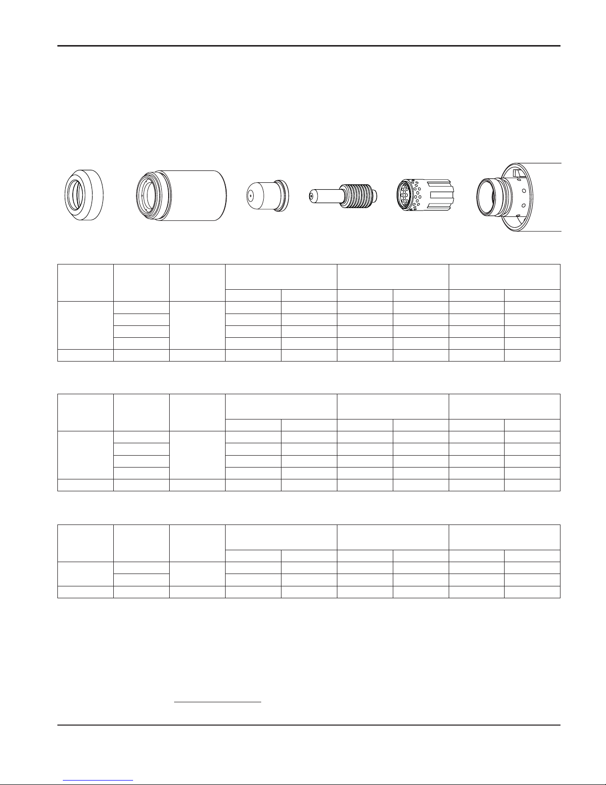
OPERATION
0
powermax1250 Operator Manual 4-19
40 amp mechanized unshielded consumables
• Torch-to-work distance for the following cut chart is 1/16 inch (1.5 mm) for all cuts.
Retaining cap
120928
Nozzle
220006
Electrode
120926
Swirl ring
120925
T80M
torch
Deflector
120979
Maximum travel speeds are the fastest travel speeds possible to cut the material without regard to cut quality.
Optimum travel speeds provide the best cut angle, least dross and best cut surface finish. Remember that cut charts
are intended to provide a good starting point for each different cut assignment. Every cutting system requires
“fine tuning” for each cutting application in order to obtain the desired cut quality.
Mild steel
Stainless steel
Aluminum
Arc
current
Arc
voltage
Pierce
delay
Material thickness
Maximum travel speeds Optimum travel speeds
inches mm
ipm mm/min ipm mm/min
25
125
0
26 ga 0.5
550 13970 353 8966
128
22 ga 0.8
484 12294 315 8001
130
18 ga 1.3
238 6045 155 3937
131
16 ga 1.5
167 4242 109 2769
40 129 0.25
14 ga 1.9
326 8280 212 5385
Arc
current
Arc
voltage
Pierce
delay
Material thickness
Maximum travel speeds Optimum travel speeds
inches mm
ipm mm/min ipm mm/min
25
127
0
26 ga 0.5
561 14249 365 9271
127
22 ga 0.8
453 11506 295 74 93
123
18 ga 1.3
500 12700 325 8255
127
16 ga 1.5
367 9322 239 6071
40 128 0.25
14 ga 1.9
220 5588 143 3632
Arc
current
Arc
voltage
Pierce
delay
Material thickness
Maximum travel speeds Optimum travel speeds
inches mm
ipm mm/min ipm mm/min
25
125
0
1/32 0.8
564 14326 366 9296
127
1/16 1.5
236 5994 153 3886
40 127 0.25
3/32 2.4
261 6629 170 4318
Page 79

OPERATION
0
4-20 powermax1250 Operator Manual
Page 80

1
powermax1250 Operator Manual 5-1
Section 5
MAINTENANCE AND PARTS
In this section:
Routine maintenance ...............................................................................................................5-2
Inspect the consumables..........................................................................................................5-3
Controls and indicators.............................................................................................................5-4
Indicator LEDs.................................................................................................................5-4
Basic troubleshooting...............................................................................................................5-5
System circuit diagram.............................................................................................................5-8
Technical questions..................................................................................................................5-9
Parts.........................................................................................................................................5-9
Torch parts.......................................................................................................................5-9
Power supply parts........................................................................................................5-10
Accessories ...................................................................................................................5-10
Page 81
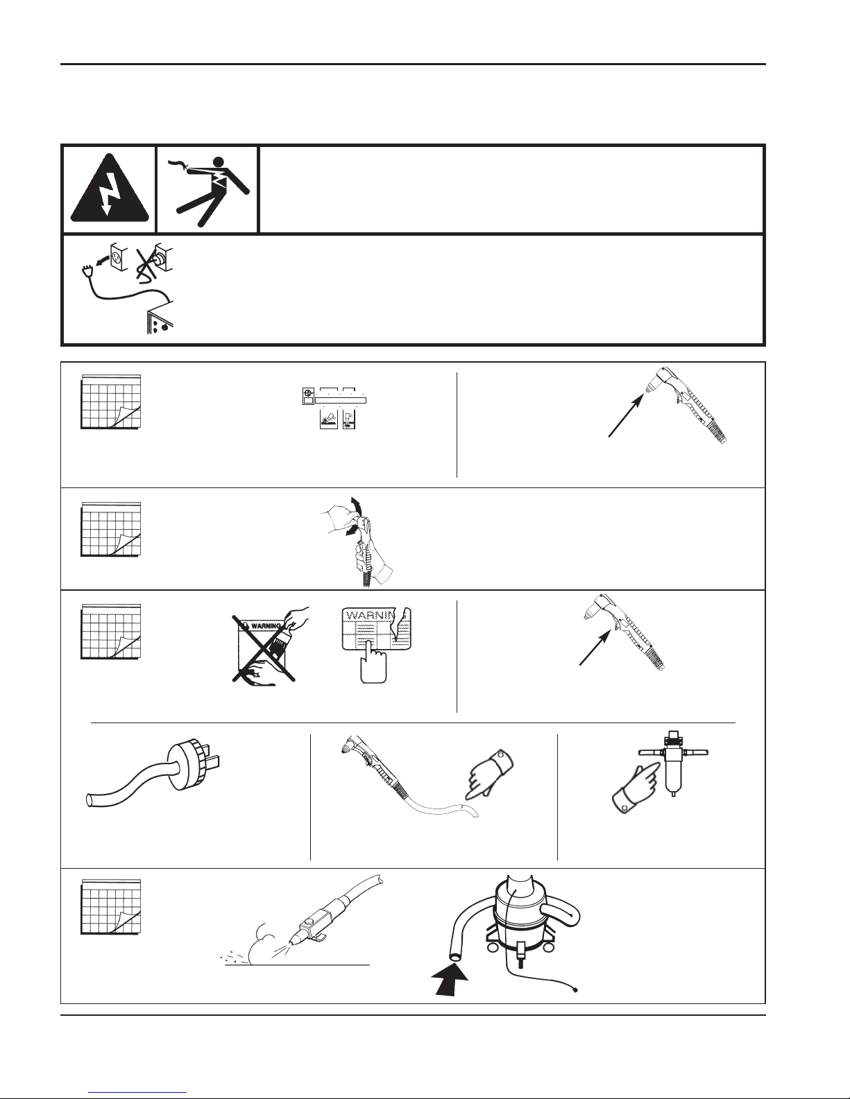
MAINTENANCE AND PARTS
0
5-2 powermax1250 Operator Manual
Routine maintenance
Each Use
6.0
BAR
5.04.0
PSI
80
7050 60
Check gas pressure.
Replace damaged power
cord or plug.
Replace damaged
torch lead.
Check pressure hose,
filter element, and
connections for leaks.
Clean the inside of
the power supply
with air pressure
or vacuum.
Replace damaged labels.
Check torch cap-on safety switch:
observe that red fault LED and yellow
torch cap LED illunimate when cap is
loosened.
Check consumables for
wear and proper installation.
Check trigger for damage. Check torch
body for cracks or exposed wires.
Each Week
6 Months
3 Months
WARNING
ELECTRIC SHOCK CAN KILL
Disconnect electrical power before performing any
maintenance.
All work requiring removal of the power supply cover must be
performed by a qualified technician.
Page 82
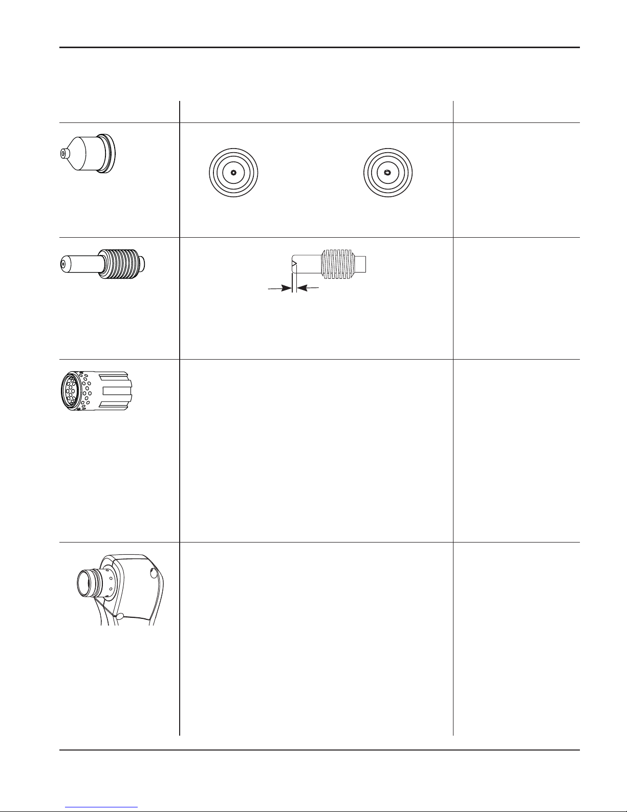
MAINTENANCE AND PARTS
0
powermax1250 Operator Manual 5-3
Inspect the consumables
Nozzle
Center hole Good Worn Replace
Roundness of through hole
Center surface Maximum pit depth Replace
1/32 inch (0.8 mm)
Electrode
Part Check for Action
External surfaces Damage or debris Replace
Central bore (I.D.) Does electrode slide easily? Replace
Gas holes Blocked holes Replace
Swirl ring
External surfaces Damage or wear Replace
Dry surface Apply a thin film of
Hypertherm grease
(part number 027055).
Torch o-ring
Max. 1/32 inch
(0.8 mm)
Page 83
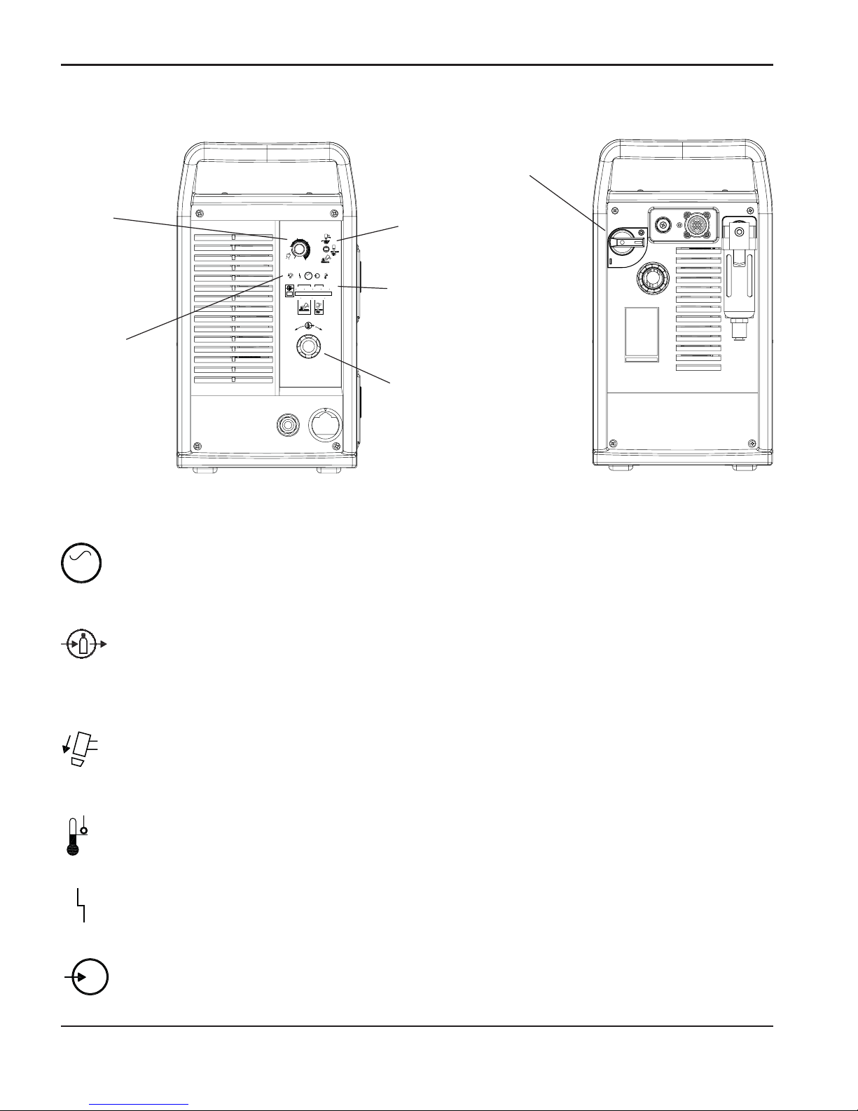
MAINTENANCE AND PARTS
1
5-4 powermax1250 Operator Manual
Controls and indicators
6.0
BAR
5.04.0
PSI
807050 60
60
40
AMPS
80
25
V
AC
+
_
Current
(amps)
adjustment
knob
Mode switch
Indicator
LEDs
Pressure
gauge
Pressure
regulator
ON (I) / OFF (0)
switch
Green power ON LED
When illuminated, indicates that power is applied to system and power switch is
ON ( I ).
Gas pressure LED
Yellow: When flashing, indicates that the gas pressure is below 60 psig (4.1 bar) for
cutting, or 40 psig (2.8 bar) for gouging.
Green: When illuminated, indicates that there is acceptable gas pressure for torch
operation.
Yellow torch cap LED
When illuminated, indicates that the retaining cap is loose or not installed.
Note: The condition must be corrected and power turned OFF and then ON again to
clear the LED.
Yellow temperature LED
When illuminated, indicates that the power supply temperature has exceeded its
operating limit.
Red fault LED
When illuminated, indicates that a fault condition exists, which prevents system
operation.
Yellow low line voltage LED
When illuminated, indicates that line voltage is below 170 VAC or above 680 VAC.
On CE units. It can also indicate a missing phase.
AC
V
Indicator LEDs
Page 84

MAINTENANCE AND PARTS
1
powermax1250 Operator Manual 5-5
Basic troubleshooting
V
AC
Problem
Cause
/ Solution
1. The ON/OFF power switch is set to
ON ( I ), and the power ON (green)
LED is not illuminated.
1.1 The power cord is not plugged into the
power receptacle.
Plug the power cord into the receptacle.
1.2 The disconnect power switch is not set to
ON or there is no power available to the
disconnect power switch box.
Turn on the power at the main power panel or
at the disconnect power switch box.
2. The power ON (green) and gas
pressure (yellow) LEDs are
flashing and the fault (red) LED
is illuminated.
2.1 The gas supply is turned OFF or not
connected to the power supply.
Check that the gas is turned on and is
connected to the power supply.
2.2 The incoming gas pressure is too low.
Set incoming gas pressure to 90-120 psig
(6.2-8.3 bar). Check that there are no leaks in
the gas supply line.
2.3 Output gas pressure is set too low for
selected mode.
Adjust gas pressure. See Section 4 for
pressure settings.
3. The power ON, low line voltage
(yellow), and fault (red) LEDs are
illuminated.
3.1 Line voltage is too low, too high, or a
phase (CE system only) is missing.
Have a qualified technician check the
incoming power.
4. The power ON (green),
temperatue (yellow) and fault
(red) LEDs are illuminated.
4.1 One of the internal thermostat switches
has opened due to overheating or
extremely low temperature.
Leave the power supply on to allow the fan to
cool the power supply (overheating). Move
the power supply to a warm location (extreme
cold).
Note: The fan turns on and off
automatically. The fan may not
be in operation even though
the power is ON ( I ).
Page 85

MAINTENANCE AND PARTS
1
5-6 powermax1250 Operator Manual
Basic troubleshooting (continued)
Problem
Cause
/ Solution
5. The power ON (green), torch cap
(yellow) and fault (red) LEDs are
illuminated.
5
.1 Retaining cap is loose or removed from
the torch.
Turn off power supply and tighten or install
torch consumables. See Section 4,
Install the
torch consumables
.
If the torch consumables become loose or
were removed while the power supply is on,
turn off the power supply, correct the problem
and then turn on the power supply to clear
this fault.
6. The arc does not transfer to the
workpiece.
6.1 The work clamp is not connected to the
workpiece, or the work clamp is broken.
Connect or repair the work clamp.
6.2 The work clamp is not making good metalto-metal contact.
Clean the area where the clamp contacts the
workpiece.
6.3 The torch is too far away from the
workpiece.
Move the torch head closer to the workpiece
and start the torch again.
See Section 4,
Hand torch operation
.
7. The arc blows out, but re-ignites
when the torch switch is pressed
again.
7.1 The consumable parts are worn or
damaged.
Inspect and change the consumables, as
necessary. See
Inspect the consumables
, in
this section and Section 4,
Hand torch
operation
.
7.2 The gas pressure is incorrect.
Adjust the operating gas pressure. See
Section 4,
Adjust gas pressure and current
setting
. Check that the gas pressure to the
power supply is not less than 90 psig
(6.1 bar) at a flow of 6.7 scfm (189 l/m).
7.3 The gas filter element outside the power
supply is contaminated.
Replace filter element.
Page 86

MAINTENANCE AND PARTS
1
powermax1250 Operator Manual 5-7
Basic troubleshooting (continued)
Problem
Cause
/ Solution
8. The arc sputters and hisses.
8
.1 The gas filter element outside the power
supply is contaminated.
Replace filter element.
8.2 There is water in the air line.
Clean air filter or add additional air filtration to
power supply. See Section 3,
Additional gas
filtration
.
8.3 Worn or incorrectly installed
consumables.
Inspect consumables. Replace if necessary.
9. Cut quality is not good.
9.1 Consumables are worn or the torch is
being used incorrectly.
See
Inspect the consumables,
in this section.
See Section 4,
Hand torch operation
.
10. The power ON (green) and fault
(red) LEDs
are flashing.
10.1 Self diagnostic failure.
System needs repair.
11. The
power ON (green) and fault
(red) LEDs are illuminated after
power is turned on.
11.1 Start signal ON when system power is
initiated.
Turn the power OFF and then ON again.
12. The power ON (green) and fault
(red) LEDs are illuminated for
10 seconds after trigger switch
is activated.
12.1 Consumables stuck or jammed.
Turn power OFF and check the
consumables.
Page 87
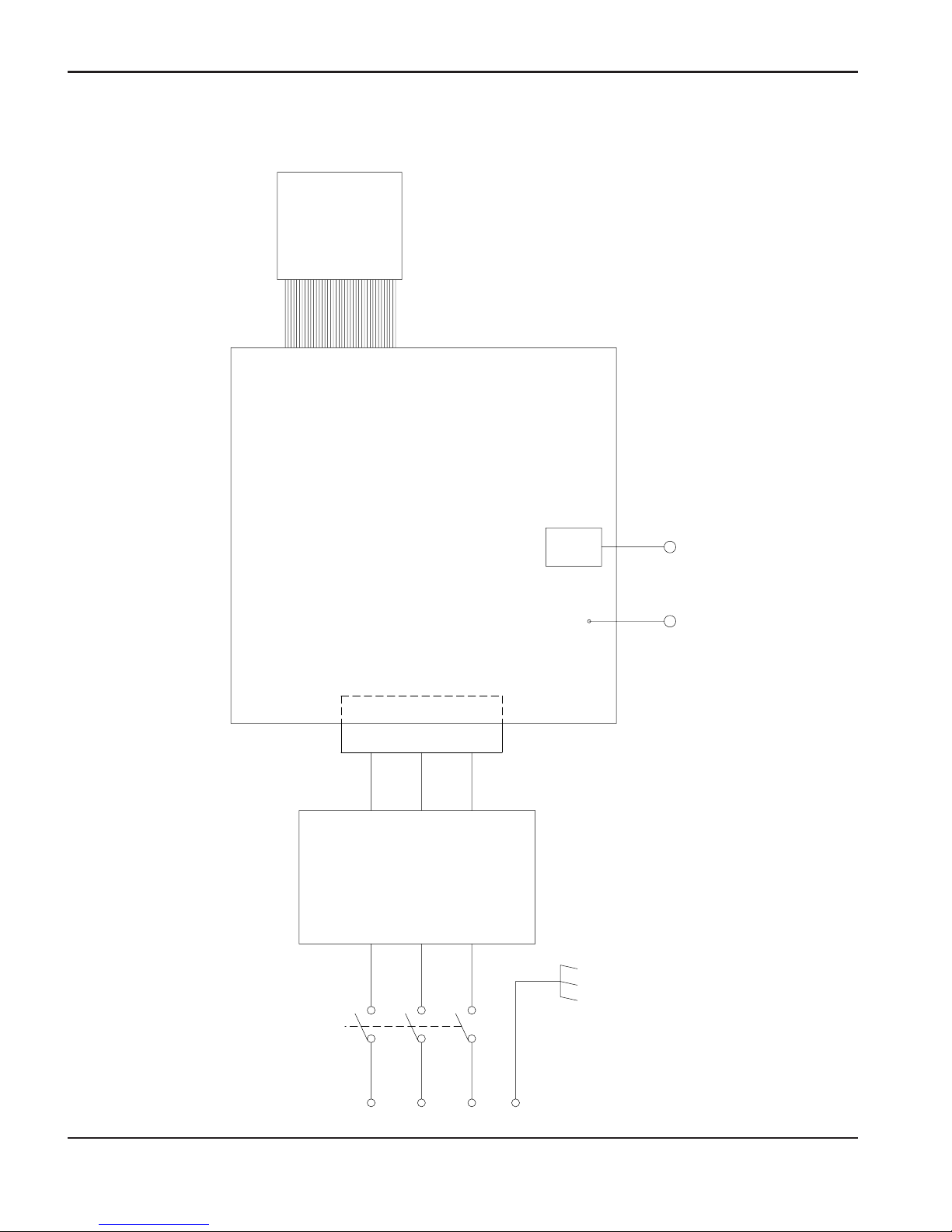
MAINTENANCE AND PARTS
0
5-8 powermax1250 Operator Manual
+
+
-
-
~
~
~
~
~
~
AC INPUT
FILTER
(CE UNIT ONLY)
POWER BOARD
ETR
WORK LEAD TORCH
40 POSITION
RIBBON
CABLE
CONTROL
BOARD
System circuit diagram
Page 88

MAINTENANCE AND PARTS
1
powermax1250 Operator Manual 5-9
Technical questions
If you are unable to fix the problem by following this basic troubleshooting guide or if you need
further assistance:
1. Call your Hypertherm distributor or authorized Hypertherm repair facility.
2. Call the nearest Hypertherm Technical Service team listed in the front of this manual.
087001 T80 hand torch assembly, 25 ft (7.6 m) lead
087002 T80 hand torch assembly, 50 ft (15.2 m) lead
087047 T80 hand torch assembly, 75 ft (22.5 m) lead
087003 T80M machine torch assembly, 15 ft (4.6 m) lead
087004 T80M machine torch assembly, 25 ft (7.6 m) lead
087005 T80M machine torch assembly, 35 ft (10.7 m) lead
087006 T80M machine torch assembly, 50 ft (15.2 m) lead
087048 T80M machine torch assembly, 75 ft (22.5 m) lead
027055 Silicon lubricant, 1/4 Oz. Tube
015337 NIP: 1/4 NPT Qdisc STL (Non-CE)
015145 Adapter: 1/4 NPT x G1/4 BSPP RH BRS (CE)
058519 Torch o-ring
128644 T80 hand torch handle replacement kit (5 screws included)
075586 T80 hand torch handle screw (5 required)
Parts
Torch parts
See Section 4,
T80 consumable configurations
and
T80M consumable configurations
, for part
numbers and illustrations of the consumables.
Page 89

MAINTENANCE AND PARTS
1
5-10 powermax1250 Operator Manual
Power supply parts
128620 Cover assembly, non-CE (12 screws included)
128621 Cover assembly, CE (12 screws included)
075533 Cover screws (individual cover screw)
128627 Filter bowl with fittings
129654 ETR door assembly
128387 Consumables box
123106 Work clamp with cable and strain relief
128666 Kit: Powermax1000/1250 power cord, standard
128667 Kit: Powermax1250 power cord, CE
128631 Kit: Powermax1250 labels
128632 Kit: Powermax1250 labesl, CE
128672 ON/OFF switch
Accessories
128646 Wheel kit
128647 Optional air filtration kit
011092 Replacement filter for optional air filtration kit
011093 Replacement filter element for filter kit
027668 Circle cutting guide — deluxe
127102 Circle cutting guide — basic
027684 Replacement bushing for circle cutting guide assembly
128145 50 ft (15 m) work cable with clamp
023206 CNC machine interface cable with voltage divider
128658 Hand torch heat shield, gouging
128650 On/off pendant for machine torch, 25 ft (7.5 m)
128651 On/off pendant for machine torch, 50 ft (15 m)
128652 On/off pendant for machine torch, 75 ft (22.5 m)
128711 Strain relief inserts, standard cord
024548 Leather torch lead sheathing
128888 FineCut kit: Powermax1000/1250/1650
128889 FineCut kit: Powermax1000/1250/1650, CE
 Loading...