

Hy-Gain LP-1009A, LP-1009AN Instruction Manual

LP-1009A / LP-1009AN
Log Periodic Antenna
Instruction Manual
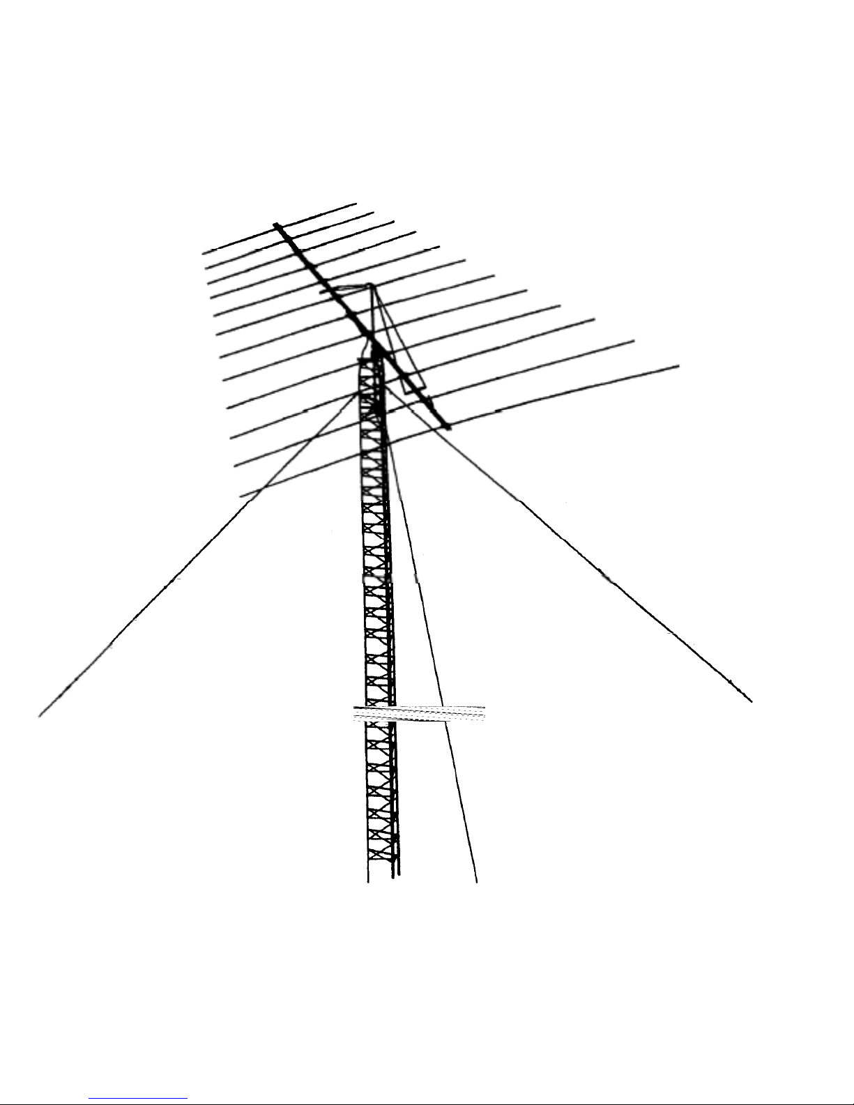

TABLE OF CONTENTS
Page CHAPTER 1
General Information .............................................................…………...........................................1-1
General Description ........................................................................................................................1-1
Theory of Operation........................................................................................................................1-2
Preparation for Assembly................................................................................................................ l-2
Installation Planning .......................................................................................................................1-3
Corrosion Precautions..................................................................................................................... l-3
Assembly of the Element-to-Boom Brackets on the Boom............................................................ l-5
Instalation of Tubing Clamps on Elements..................................................................................... l-6
Element Assembly ..........................................................................................................................1-8
Feedline Assembly.......................................................................................................................... l-9
Beta Tube Assembly .....................................................................................................................1-12
Installing Elements on the Boom..................................................................................................1-15
Balun Assembly............................................................................................................................1-15
Boom Support Assembly..............................................................................................................1-16
Final Inspection.............................................................................................................................1-17
CHAPTER 2
Antenna Installation.................………………....................................................................................... 2-1
Installation on a Crank-Up Tower............….................................................................................. 2-1
Installation on Guyed Towers........................................................................................................ 2-1
Attachment of Coaxial Feedline.................................................................................................... 2-1
Attaching the Antenna to the Mast................................................................................................ 2-2
Lightning Protection ...................................................................................................................... 2-2
VSWR Curves................................................................................................................................ 2-3
Operation........................................................................................................................................ 2-4
VSWR Record ............................................................................................................................... 2-4
Troubleshooting ............................................................................................................................ 2-5

LIST OF ILLUSTRATIONS
FigurePage
1 Boom-to-Mast Bracket................................................................................................ l-4
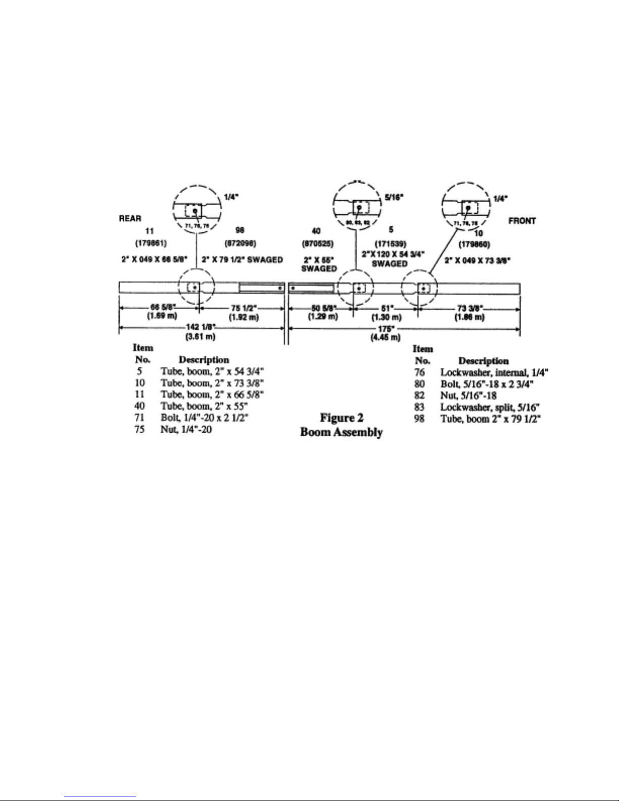
2 Boom Assembly.......................................................................................................... l-5
3 Element Location .......................................................................................................1-6
4 Element-to-Boom Bracket.......................................................................................... l-6
5 Element Tubing Clamps.............................................................................................. l-7
6 Rope Dampening .......................................................................................................1-8
7 Element Tubing Descriptions...................................................................................... l-9
8A Exposed Tubing Lengths, LP-1009, American........................................................1-10
8B Ex posed Tubing Lengths, LP-1009, Metric.............................................................1-11
9 Feedline Assembly, Front Section ...........................................................................1-12
10 Feedline Assembly, Middle Sections.......................................................................1-13
11 Feedline Assembly, Rear Section ..............................................................................1-14
12 Installing Elements on the Boom...............................................................................1-15
13 Boom Support Cable Assembly.................................................................................1-16
CHAPTER 1
General Description
The LP-1009 log-periodic antenna is a medium
gain unidirectional antenna with an instantaneous
bandwidth of 13 to 30 MHz under 2:1 VSWR.
The LP-1009 also covers the 10,12,15,17 and 20
meter Amateur bands. It is supplied with the new
HyGain BN-4000 high power balun which allows
the antenna to handle 2000 watts continuous-duty
and 4000 watts PEP on all modes.
All-stainless steel hardware an d cl amps are used
on all electrical and mechanical connections of
the LP-1009.
HyGain's T2X or HDR-300 rotators, and may be
installed on any tower rated for at least 12.5 squa re
feet wind load.
The LP-1009 may
be rotated
with

Theory of Operation
Preparation for Assembly
The design of the LP-1009 is based on a 12
element log-periodic dipole array with a 'TAU'
of 0.896 and a'SIGMA' of 0.05. These
parameters give the LPDA a gain of
approximately 7.2 dBi, a front-toback ratio of
approximately 17 dB, and maximum VSWR of
1.8:1. The mechanical design of each element
was optimized by computer analysis to provide
minimum weight and wind area yet survive wind
speeds of at least 100 mph (165 kph).
The United States uses American units of
measurement. Please see page 2-8 of this manual
for American-to-metric conversion information.
Most illustrations in this manual contain both
American and metric dimensions.
When unpacking your antenna, check inside of all
tubing for smaller diameter tubes and other small
parts. To conserve space, these smaller parts are
sometimes packed inside larger pieces. Check all
parts against the parts list to ensure no parts are
missing. The hardware supplied with this antenna
is bagged by thread size for your convenience.
You may want to sort the aluminum tubing for
the elements before assembly. This makes
element assembly much easier. The following
table shows the various element tubing sizes and
quantities.
TUBING SIZE QUANTITY SUPPLIED
1 1/4" x 64 3/4" with insert 2
1 1/4" x 59" with insert 2
1 1/4" x 37 3/4" with insert 2
1 1/4" x 20 1/2" 2
1 1/4" x 17" 2
1 1/4" x 15" 6
1 1/8" x 42" 2
1 1/8" x 36" 4
1 1/8" x 317/8" 4
1 1/8" x 17" 6
7/8" x 55" 4
7/8" x 51 " 4
7/8" x 46" 4
7/8" x 34" 4
7/8" x 24" 4
7/8" x 15" 4
5/8" x 28" 2
5/8" x 24" 20
5/8" x 16" 2
7/16" x 58" 2
7/16" x 55" 6
TABLE 1
Choose a large, clear area to assemble your
p
antenna. The area must be at least 28' x 38' (8.5
m x 11.6 m). You may wish to use a temporary
mast with sawhorses to support the boom during
assembly. A concrete driveway or parking area is
an excellent area for assembly. If you assemble
this antenna over a grassy area, precautions
should be taken so that hardware is not
accidentally lost during assembly. We have
included some extra small parts with this
roduct, just in case some are lost.
All tubing supplied with the LP-1009 antenna
telescopes together. Make all measurements to
the given dimensions, plus or minus no more
than 1/8 inch (3 mm).
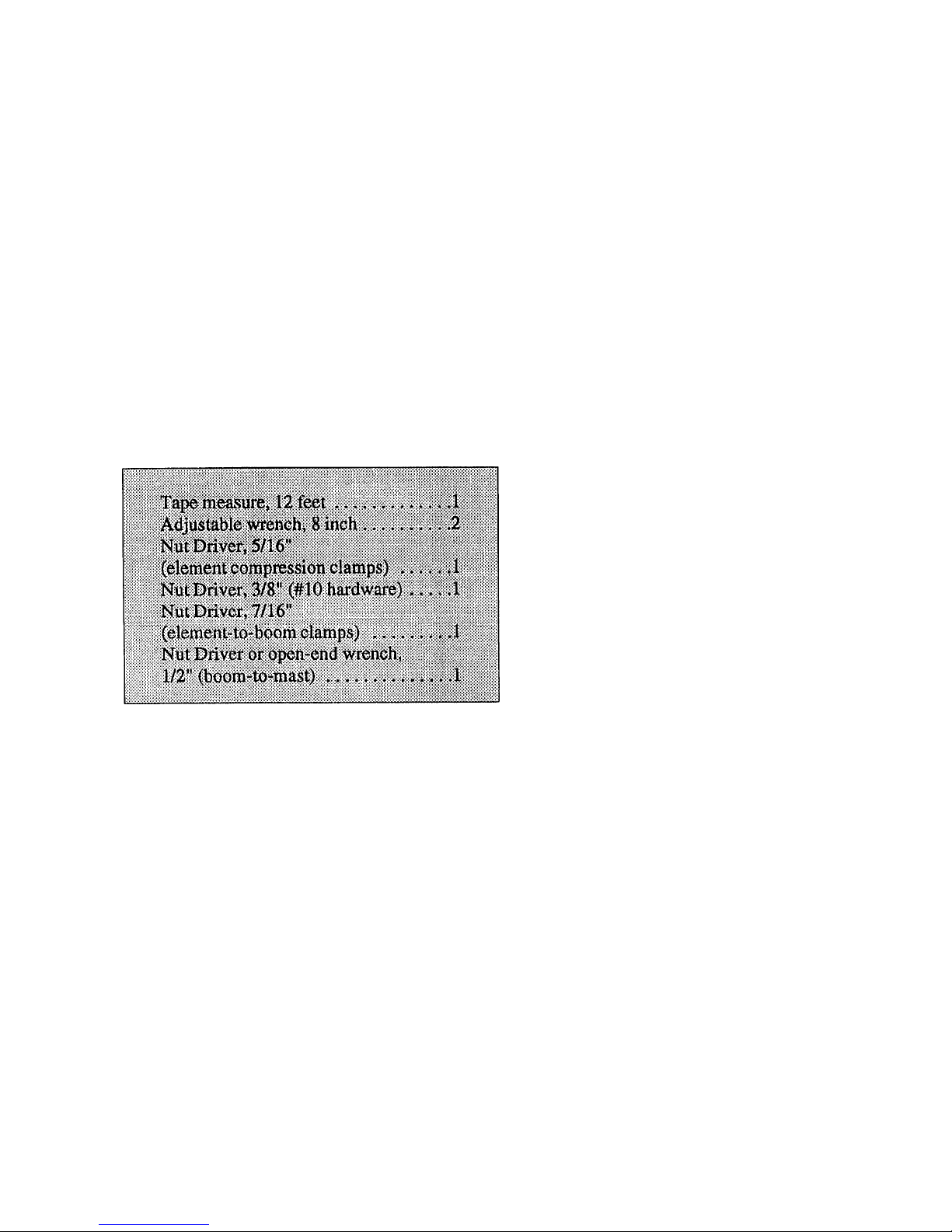
TOOLS: The following tools are required for
easy assembly.
Installation
The Hy-Gain LP-1009 Log-Periodic Antenna requires a supporting tower structure which is at
least 50' (15.2 m) in height above ground level
and which will support at least 12.5 sq. ft. (1.1
sq. m) wind surface area. A support mast is not
supplied with this antenna. Mast height will vary
according to installation. A standard 10 foot mast
will suffice in most cases. This antenna may also
be installed atop buildings or other structures. In
these cases, the antenna should be at least 10' (3
m) above a peaked roof and at least 20' (6.1 m)
above a large flat roof. Performance may be
degraded at less than these heights, depending
upon the amount of metal in the roof and/or attic.
Other nearby antenna structures, power lines,
and guy wires may also affect the performance
of this antenna.
The LP-1009 also requires a suitable rotator, if
not installed in a fixed azimuth. Suitable rotators
include Hy-Gain models T2X and HDR- 300.
We suggest that the assembly of this product be
done over at least a 2 day period. We further
suggest that you read this manual thoroughly, in
its entirety, and then go through the manual a
second time and identify and familiarize yourself
with all of the antenna components. Start
assembling the antenna when you are prepared.
A few extra minutes invested in the assembly
process will ensure many years of satisfaction
with this antenna.
NOTE: An extra page that contains Figures 8A
and 8B, Element Assembly, has been inserted in
this manual for use when assembling the
elements.
Corrosion Precautions
The LP-1009 antenna is designed to be relatively
maintenance free for most environments. All
hardware is made of passivated stainless steel,
typically grade 304. The internal tooth-type
lockwashers used in this antenna are grade 410
stainless steel, and are slightly magnetic. The
element tubing clamps are grade 304 stainless
steel. The set of boom support clamps is hot
dipped galvanized steel. Most other metallic
parts are aluminum. All insulators exposed to
sunlight are made from U.V. resistant black
polyethylene or black Cycloac.
We have supplied a 3 oz. tube of Penetrox-ATM
from Burndy Corporation for use as an antioxidant within element tubing assemblies. This
prevents aluminum oxide from forming on the
aluminum surfaces, especially in coastal
environments.
Before assembling the tubing sections, abrade
the mating surfaces with a wire brush or
sandpaper. Apply the anti-oxidant to both
surfaces, then assemble joint. Wipe off any
excess material.
A light amount of clear lacquer or an acrylic
spray may be used to coat the exterior surface of
the element assemblies if this antenna is to be
installed near a sea coast. Tighten all joints
securely before coating! Also, if installed near a
sea coast, the solder lugs on the pigtail wire
assemblies should not touch the aluminum tubing
or clamp directly. Each solder lug should be
between 2 stainless steel flatwashers. Tighten
these connections securely and competely coat
with Scotchkote or RTV.
NOTE: Only use alcohol-based RTV (non-corrosive). The acid-based RTV (which releases
acetic acid and smells like vinegar) will corrode
metal.
If a UHF connector (PL-259) is used with the
BN-4000 balun, seal the connector with CoaxSeal (TM) or black electrical tape for rain
protection. Type N connectors are designed to be
weatherresistant if tightened securely.
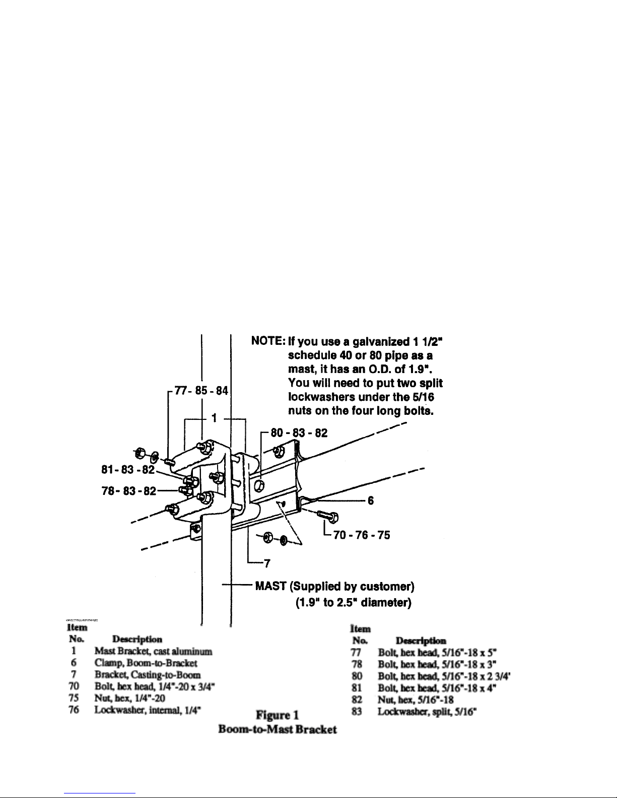
Select the boom-to-mast bracket and clamp parts.
Loosely assemble them on the boom ends as
shown in Figure 1.
Secure the boom ends and brackets together with
four (4) 1/4"-20 x 3/4" bolts, lockwashers and
nuts (70, 75, 76), and two (2) 5/16"-18 x 2 3/4"
bolts, lockwashers and nuts (80, 82, 83 ). Tighten
these six bolts securely. The casting-to-boom
bracket (7), may deform slightly when the four
1/4" bolts are tightened. This is normal.
Assemble the two cast aluminum brackets (1) on
your temporary mast at about 4 feet (1.2 m)
above ground. A seven foot length of 2" ABS or
PVC plastic drain pipe makes an inexpensive
temporary mast. Secure the two brack ets together
using the two (2) 5/16"-18 x 3" bolts,
lockwashers and nuts (78, 82, 83). Tighten these
two bolts evenly until the brackets are snug.
Attach the boom and bracket assembly to these
two brackets using the four (4) 5/16"-18 x 5"
bolts, lockwashers and nuts (77, 82, 83). If you
have problems aligning all of the holes in the
brackets, you may wish to carefully run a 5/16"
drill bit through these holes. Do not enlarge
these holes beyond 5/16" or you may weaken the
brackets. This will prevent alignment problems
that might occur on the top of your tower!
Tighten these four bolts just enough to hold the
weight of the antenna.
Slip the remaining boom sections over the
swaged ends of the assembled boom and secure
as shown in Figure 2.
Assembly of the Element-to-Boom
Brackets on the Boom
There are two sizes of element-to-boom brackets
supplied with the LP- 1009 antenna. The largest
has a 1 1/2" I.D., and is used on the 8 longest
elements and the boom support tubes. The
remaining brackets have a 11/4" I.D., and are
used on the 4 front elements.
The largest brackets are stamped with the
number 14, while the smaller brackets are
stamped with the number 13.
Assemble the brackets as shown in Figure 4 and
locate them on the boom assembly as shown in
Figure 3. It is easier to assemble the brackets on
the boom at the correct location, rather than try
to slide them on the boom. If you are going to
leave this assembly unattended for more than 15
minutes, we suggest that you tighten the eight
(8) bolts on each bracket, so that they do not
vibrate off. Do not tighten the anchor bolt on the
bottom of the brackets until the elements are
installed and aligned. Install the boom support
tubes (17) and brackets (2) also at this time! The
boom support brackets will have both top and
bottom anchor bolts.
NOTE: The longest element (#12) uses top AND
bottom anchor bolts! All other elements use only
bottom anchor bolts!
 Loading...