

Hy-Gain Hy-Range V 674B Instruction Manual
Your Hy-Range V is a full 23-channel AM/SSB transceiver designed
and licensed for Class 0 Citizen Band operation as designated by the
Federal Communications Commission (F .C.C.).
The Hy-Range V is a completely solid state compact unit of high
reliability and low power consumption. This transceiver utilizes
a highly advanced, unique system of frequency synthesization enabling
immediate operation on all 23 channels without the need of additional
crystals or adjustments. This unit also features a fine tune control
allowing you to make adjustments for stations which may operate
slightly off frequency. Additional features include an AN L (Auto-
matic Noise Limiter/NS (Noise Silencer) switch which reduces un-
desirable noises.
The Hy-Range V AM/SSB transceiver is designed to operate from
11.5 to 14.5 VDC. To obtain the best results from your transceiver,
it is suggested that you read all the instructions contained in this
manual.
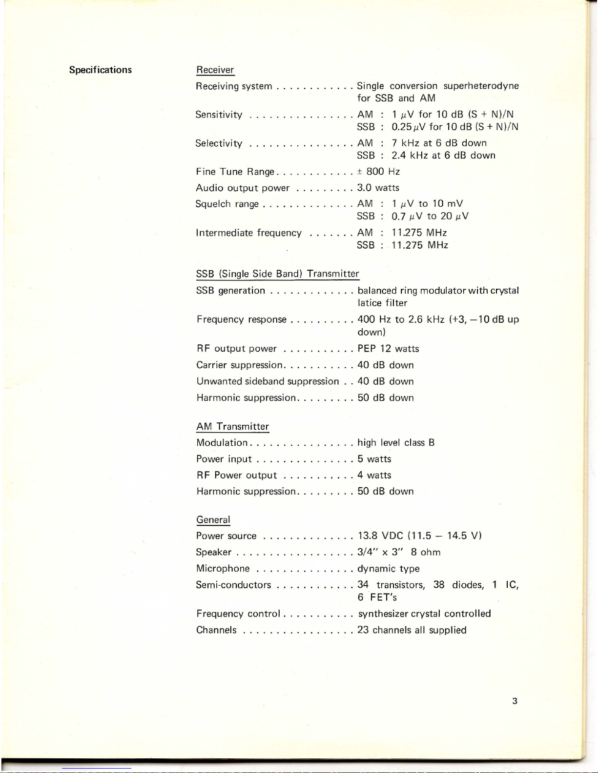
Receiver
Receiving system .......•.... Single conversion superheterodyne
for SSB and AM
Sensitivity AM 1 /lV for 10 dB (S
+
N)/N
SSB 0.25"N for 10 dB (S + N)/N
Selectivity AM 7 kHz at 6 dB down
SSB 2.4 kHz at 6 dB down
Fine Tune Range ± 800 Hz
Audio output power 3.0 watts
Squelch range AM 1 /lV to 10 mV
SSB 0.7 /lV to 20 /lV
Intermediate frequency AM 11.275 MHz
SSB 11.275 MHz
SSB (Single Side Band) Transmitter
SSB generation balanced ring modulator with crystal
latice filter
Frequency response 400 Hz to 2.6 kHz (+3, -10 dB up
down)
RF output power PEP 12 watts
Carrier suppression 40 dB down
Unwanted sideband suppression .. 40 dB down
Harmonic suppression 50 dB down
AM Transmitter
Modulation high level class B
Power input 5 watts
RF Power output 4 watts
Harmonic suppression 50 dB down
General
Power source ..........•... 13.8 VDC (11.5 - 14.5 V)
Speaker 3/4" x 3" 8 ohm
Microphone dynamic type
Semi-conductors 34 transistors, 38 diodes, 1 IC,
6 FET's
Frequency control synthesizer crystal controlled
Channels 23 channels all supplied
Licensing your Citizens
Two-way
Radio in the
United
States
NOTICE:
It
is illegal to transmit with this transceiver until you obtain
your citizens two-way radio Class D license. You are also required to
read and understand Part 95 of the Federal Communications Com-
mission rules and regulations before operation of this unit. License
application Form 505 is packed with your transceiver and Part 95
of the regulations may be available from your dealer; if not, you may
obtain copies from the Superintendent of Documents, Government
Printing Office, Washington, D.C. 20402.
It is also prohibited by the F.C.C. to adjust the transmitter circuit of
this unit unless you hold a current First or Second Class Radio-
telephone License.
We recommend that you refer all servIcing of any Hy-Gain products
to your nearest Hy-Gain warranty service center or consult your
Hy-Gain dealer or distributor for the service center location nearest
you. Do not tamper with any internal adjustments or settings - - such
tamperi ng can adversely affect the performance of you r transceiver
or may, in fact, cause your unit to operate beyond the limitations
set forth for Class D citizens two-way transceivers by the F.C.C.
General Considerations
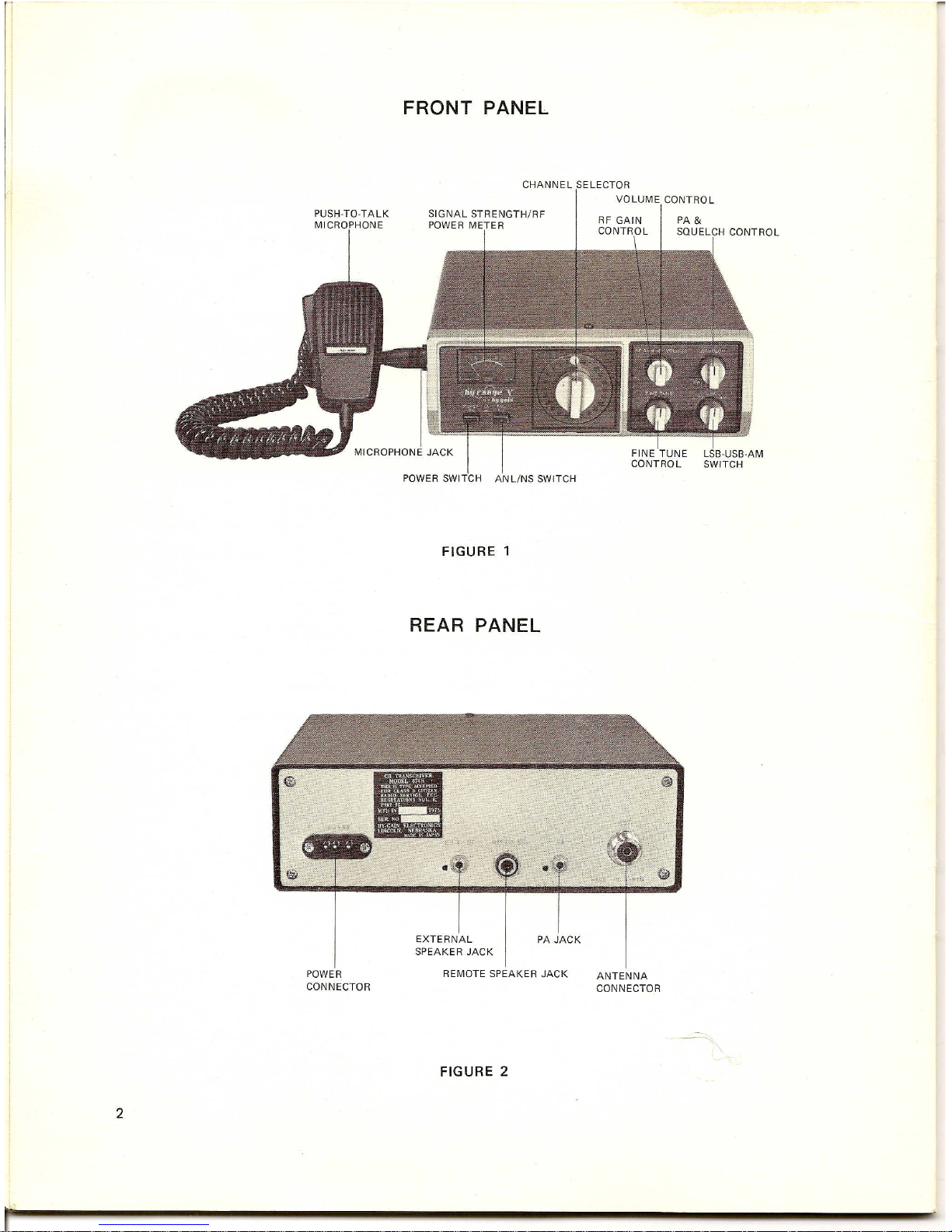
Choose a location which is convenient to the operating controls, and
will not interfere with the normal functions of the driver. The trans-
ceiver may be mounted to the underside of the instrument panel or
dashboard of a car, truck, boat, etc., by means of the special bracket
supplied with your transceiver.
Mounting Bracket
Attach the bracket to the underside of the instrument panel using
four or more screws (see Figure 3). Secure the transceiver to the
bracket by means of the large thumb screws.
DC Power Connections
The Hy-Range V may be operated from a nominal 12 VDC battery
source on negative or positive ground systems.
NOTE: Before making any power connections, determine whether
the vehicle has a negative or positive ground electrical system, then
make the following connections:
Connect the red lead to the vehicle
"+"
(positive) side of the electrical
system, and the black lead to the vehicle (negative) side of the
electrical system.
In the case of negative ground vehicles, the red lead should be con-
nected to the accessory post on the ignition switch, the voltage
regulator side of the ammeter or the accessory side of the fuse block.
The black lead should be connected to the metal firewall or any other
point that is connected to the vehicle chassis (ground).
 Loading...