

Hy-Gain DX-88 Instruction Manual

8-Band HF Vertical
80 thru 10 Meters
Model DX-88
Instruction Manual

Please record the following information for your records: Date
of Purchase: _____________________________________________
Purchased From:______________________________________________
Price Paid:__________
Please retain your copy of the Bill-of-sale for warranty claims.
TABLE OF CONTENTS
Chapter 1..........................................................................................................................................1-1
General Description .………...........….............................................................…............................1-1
Electrical Design..............................................................................................................................1-1
Mechanical Design….........…...........................................................................................................1-1
Specifications .....................….........................................................................................................1-2
Typical VSWR Curves..........….......................................................................................................1-2
Chapter 2.........................................................................................................................................2-1
Preparation for Assembly ...............................................................................................................2-1
Tools..................................…................................................................................................2-1
Chapter 3.....................................................................................................................................3-1
Base Assembly...........................................................................................................................3-1
80/40 Meter Assembly..............................................................................................................3-1
Capacitor Assembly..........................................................................................................................3-1
Attaching Capacitors to Coil Assembly.........................................................................................3-1
10/12/15 Meter Trap Assembly ..................................................................................................3-3
Capacitor Assembly ......................................................................................................................3-3
Attaching Capacitor to Coil Assembly..............................................................................................3-4
17/20 Meter Assembly ....................................................................................................................3-5
Capacitor Assembly ......................................................................................................................3-5
Attaching Capacitors to Coil Assembly.........................................................................................3-6
30 Meter Trap Assembly ..................................................................................................................3-7
Attaching Capacitors to Coil Assembly.................................................................................. .....3-7
Attaching Upper Radiator Tubes to 30 Meter Trap Assembly.......................................................3-8
Installation of Tubing Clamp.........................................................................................................3-9
Attaching the Trap Assemblies.................................................................................................. 3-10
DC Shorting Coil.......................................................................................................................... 3-10
Tuning the DX-88 Vertical Antenna.......................................................................................... 3-12
Chapter 4......................................................................................................................................4-1
Mounting the Antenna ......................................…………............................................................4-1
Operation ...................................................................................................................................4-4
Service Information .....................................................................................................................4-4
VSWR Record.....................................…......................................................................................4-5
Converting American Measurements to Metric......................................…...................................4-6
Chapter 5....................................................…...............................................................................5-1
Parts List......................................................................................................................................5-1
LIST OF ILLUSTRATIONS
e
ag
g
g
Figure Page
1 Base Assembly 3-1
2 80/40 Meter Assembly 3-2
Detail A 45” Capacitor Assembly 3-2
Detail B 1 1/8” x 1” Mast/Capacitor Clamp 3-2
Detail C 1 1/8” x 7/16” Mast/Capacitor Cla mp 3-2
3 10/12/15 Meter Capacitor Assemblies 3-3
Detail A 13” Capacitor Assembly 3-3
Detail B 16” Capacitor Assembl y 3-3
4 10/12/15 Meter Trap Assembly 3-4
Detail A 1 1/8” x 1” Mast/Capacitor Clamp 3-4
Detail B 1 1/8” x 7/16” Mast/Capacitor Cla mp 3-4
5 17/20 Meter Capacitor Assemblies 3-5
Detail A 13” Capacitor Assembly 3-5
Detail A 16” Capacitor Assembly 3-5
6 17/20 Meter Trap Assembly 3-6
Detail B 1 1/8” x 1” Mast/Capacitor Clamp 3-6
Detail C 1 1/8” x 7/16” Mast/Capacitor Cla mp 3-6
7 30 Meter Trap Assembly 3-7
Detail A 1” Mast/Capacitor Clamp 3-7
Detail B 3/8” x 1” x 3/8” Mast/Capacitor Clamp 3-7
8 Upper Radiator Tubes Attached to 30 Meter Trap Assembly 3-8
9 Tubing Cla mps 3-9
10 DC Shorting Coil 3-10
11 Connecting Trap Assemblies 3-11
12 DX-88 Overall View 3-16
13 DX-88 Ground Mount Radial System 4-1
14 DX-88 Resonant Radial System 4-2
15 Roof Mounted Radial System 4-3
LIST OF GRAPHS AND TABLES
Graph Page
1 Dimension A and B, 80/40 Meter for 6.9-7.3 MHz 3-13
2 Dimension A and B, 80/40 Meter for 3.5-4.0 MHz 3-13
3 Dimension C, 10 Meter Trap for 27-29.7 MHz 3-13
4 Dimension D, 12 Meter Trap for 24.5-26.5 MHz 3-13
5 Dimension E, 15 Meter Trap for 20.5-22 MHz 3-14
6 Dimension F, 17 Meter Trap for 17.5-18.5 MHz 3-14
7 Dimension G, 20 Meter Trap for 13.5-15.5 MHz 3-14
8 Dimension H, 30 Meter Trap for 9.5-10.5 MHz 3-14
Tabl
1 Dimension H and I for HAM and SWL Settings.....................…...........................3-15
2 Broadcastin
3 Resonant Radial Len
Frequencies.......................................................................................3-15
P
ths ........................................................................................4-3

CHAPTER I
GEN
ON
g
pp
gh-Q p
,
ERAL DESCRIPTI
The Hy-Gain DX-88 is an omnidirectional, unity
gain, self supporting vertical antenna that
operates in the Amateur 10, 12, 15, 17, 20, 30,
40, and 80 meter bands. This vertical antenna
may also be tuned to provide outstanding
reception in the SWL 11, 13, 16, 19, 22, 25, 31,
41, 49, 74, and 90 meter bands. The DX-88 will
work against an earth ground and a set of ground
radials or a resonant radial system when
mounted above ground. You may construct your
own radial system from information in this
manual, or you may purchase the optional
ground radial kit for the DX-88, Model GRK-88,
Order No. 189S, or the resonant roof radial kit,
Model RRK-88, Order No. 1905.
An optional 160 meter kit, Model 160 MK-88,
Order No. 191S, is also available for the DX-88
vertical. The 160 meter kit is only recommended
for
round-mounted installations.
Dimensions are included in this manual for optimization on either the CW or phone portions of
the 80, 40, and 20 meter bands. Regardless of
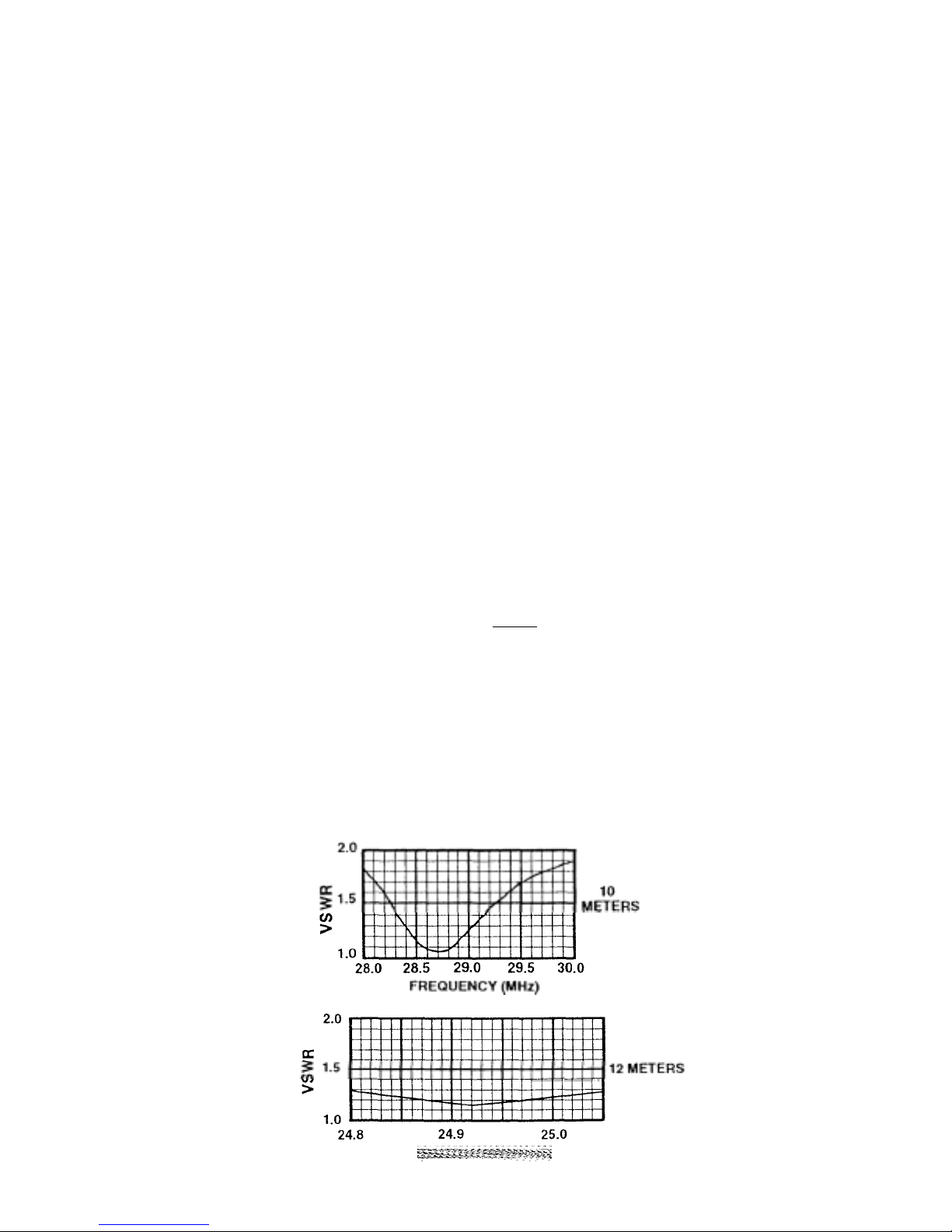
the optimization, the VSWR bandwidths of the
DX-88 are broad enough for the antenna to
operate at a VSWR of 2:1 or less on the 10, 12,
15, 17, and 30 meter bands. The bandwidth on
80 meters is approximately 50 KHz at 2:1
VSWR, because it is inductively loaded on this
band. The bandwidth on 40 meters is
approximately 200 KHz, and on 20 meters
roximately 250 KHz.
a
The Omni DX-88 vertical antenna features stainless steel hardware for all electrical and most
mechanical connections. The DX-88 also
features heavy-wall 1 3/8 inch and l 1/8 inch
aluminum tubing for high strength and large
diameter #12 copper wire coils for low loss and
hi
A high-efficiency non-automatic band-switching
kit is available to add 160 meter operation to the
DX-88
erformance.
Model 160 MK-88, Order No. 00191S.
ELECTRICAL DESIGN
The Omni DX-88 vertical antenna utilizes its
entire length for radiation on both 80 and 40
meter s .
It resonates on each of these two bands with the
aid of a tuned circuit near the base which looks
inductive in the 3.5 - 4.0 MHz band and
capacitive in the 7.0 - 7.3 MHz band. Adjustable
piston capacitors set the resonance of this tuned
circuit, which affects the amount of inductance
and capacitance, and the resulting antenna
resonances within each band.
The remaining bands are obtained by using lowloss, high-Q tunable traps to isolate one-quarter
wavelength sections along the radiator. Onequarter wavelength sections always produce lowangle radiation patterns without high-angle
lobes. The distances between the traps are fixed
and the traps themselves are tuneable, except for
the 30 meter band. This allows the antenna to
operate on the new WARC bands of 12 and 17
meters as well as the older 10, 15, and 20 meter
bands. This also allows the DX-88 to resonate on
or very close to the international SWL bands,
with the proper adjustment of each trap.
MECHANICAL DESIGN
The DX-88 mechanical design features 0.120
wall, 1 3/8 inch and 1 1/8 inch 6063T832
aluminum tubing for extra high strength. Wind
survivability is 75 MPH WITHOUT guying. The
large diameter coils used in the traps and 80/40
tuning circuit are constructed on large diameter
high strength forms and are protected from
environment by covers made from the same
material. The DX-88 may be disassembled into
sections of less than 55 inches for easy
transportation to DX locations. All stainless
steel hose clamps and hardware are used for all
electrical connections. All insulators and coil
covers are UV protected. The coil covers may be
removed easily for cleaning, modifying or
repairing the coils. When the 160 meter kit has
been added, the wind survivability is 50 MPH
SPECIFICATIONS
pp
Frequency:
Transmit .............................……….................... 80, 40, 30, 20, 17, 15, 12, 10 meter Am a t e u r Bands
Receive...............................……………..................... 3-30 MHz, tunable in 8 International SWL Bands.
Input impedance . ...................…………………………………………………………………….50 ohms
VSWR at resonance..................................………………le ss than 1.5:1 if using recommended' radial' system
Maximum Power* ...... ................... ... ..... 1500 watts PEP, 700 watts average
Input Connector ................... . .... . .. .. ............. 'SO-239 *
Maximum power on 30 meters is 250 watts a v e r a g e
*Maximum power on 17 meters is 500 watts average
Mechanical
Maximum height... ……………………………………………………………………… ....24' 9" (7.54 m)
Weight, net ........................................................……………………………………... 18 lb. (8:2 kg)
Weight, shipping ................... ........ ......... ......... .....::.......... _:....... ....................22 lb. (10.0 kg)
Recommended Mast O.D. (Mast not supplied)............................... 1 1/2" - l 5/8" (38 - 41 mm)
Wind Survival, unguyed.......................................................................... ......75 MPH (121 kmph)
Wind Survival, unguyed with 160 MK-88................................. ................... 50 MPH (80 kmph)
NOTE: If the terminals of the input connector
are checked with an ohmmeter, they will show
an open. THIS IS NORMAL! A DC shorting
coil may be constructed from information in
this manual. This coil will also improve the
impedance match on the 80 meter band.
CAUTION: Do Not use a support mast smaller
than 1 1/2" O.D. (38 mm). Small masts will not
ort this antenna.
su
TYPICAL VSWR CURVES:
CAUTION: When using RTTY or AM, DO
NOT transmit continuously at maximum power
for more than 5 minutes at a time, with 5
minutes off between transmissions. Do not
exceed average power limits specified for each
band.
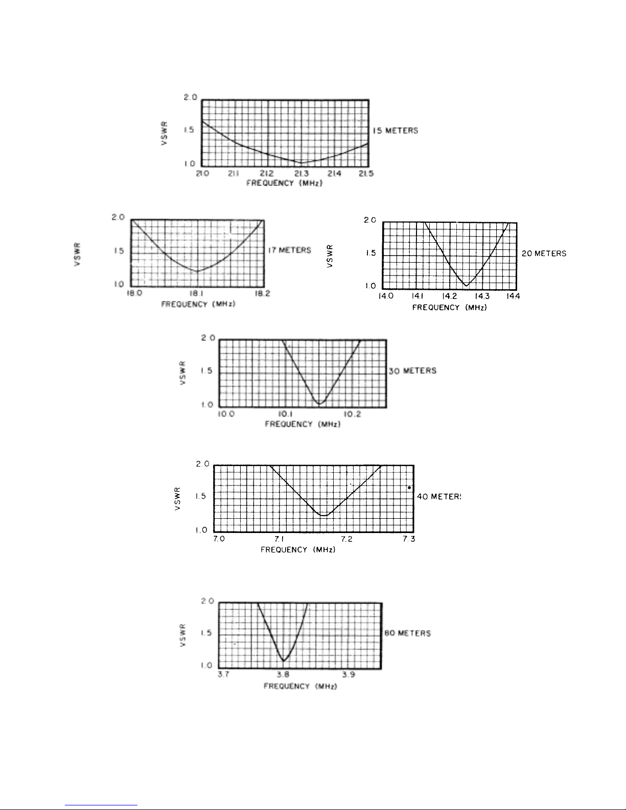
TYPICAL VSWR CURVES Cont.

C
HAPTER 2
PREPARATION FOR ASSEMBLY
FOR OVERSEAS CUSTOMERS: If you use
the Metric System, see the American-ToMetric conversion table in the rear of the
manual. The illustrations in this manual will
provide both American and Metric
Choose a table-top or similarl y sized clear area
to assemble the Omni D X-88 vertical an tenna.
A bench-vise may be used to hold the tubing
during assembly. If you assemble this antenna
over a grassy area, precautions s hould be taken
so that hardware is not ac cidentall y lost during
assembly.
Tools: The following tools are required
-
Tool Type Qty
Tape measure, 12 ft............ ... .... .... .... . 1
Nut driver, 3/8 inch ..... ..................... 1
Nut driver, 5/16 inch ................ ........ . 1
Open-end wrench, 1/2 inch .... .... .... .... 1
Open-end wrench, 7/16 inch.............. 1
Standard wrenches or adjustable wrenches
When unpacking your antenna, check inside of
all tubing for small parts and elements. To
conserve space, these smaller articles are
sometimes put inside larger pieces. Check all
parts against the parts list in the rear of this
manual to ensure no parts are missing. There
should be 4 coil assemblies. These may be
identified by comparing t hem to Figures 2, 4,
6, and 7.
Make all measurements to the given dimensions, plus or minus not more than 1/8 inch.
The assembly of the DX-88 will be easier if
you read this manual completely through at
least twice and follow the recommended
directions. Allow at least 3 hours for
assembly.
You may wish to assemble the DX-88 in
sections in a covered area (basement, garage
or workshop etc.) out of the weather and then
brought outside for final assembly and
installation. The Major sections are:
Base Assembly
80/40 Assembly
10/12/15
Assembly 17/20
Assembly
30 Assembly with Item 11
Top Assembly - Items 2 and 10
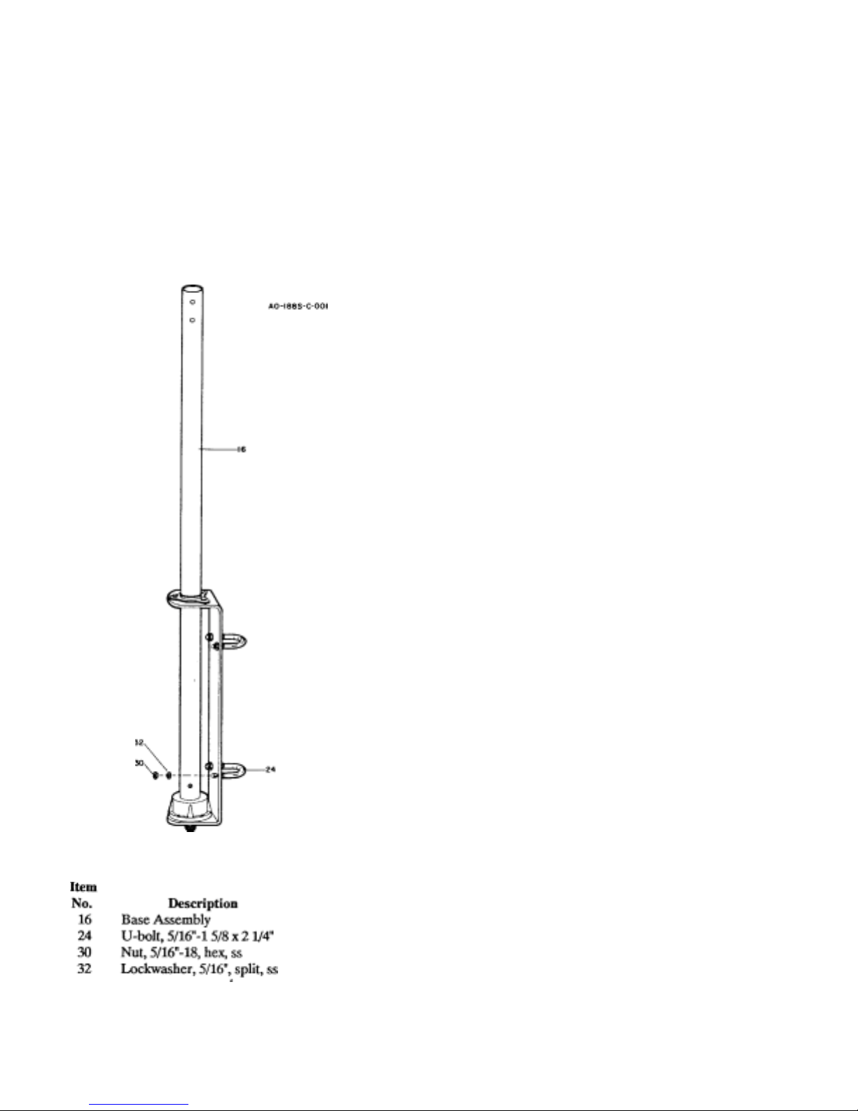
BASE ASSEMBL
Y
ac
Capacitors to Co
80/40 METER ASSEMBLY
Select the DX-88 base assembly and assemble
Capacitor Assembly
Construct the two 45" capacitors for th e 80/40
meter assembly. Select a 1" x 45" tube (Item
3), 7/16" x 48" tube (Item 1), 3 spacers (Item
35), 1 rain cap (Item 36), and 1 caplug (Item
34) for each capacitor assembly. Refer to
Figure 2.
Push the spacers onto the 7/16" tube and adjust
so that the top spacer is approximately 20
inches from the top en d of th e t ube, th e bo tto m
spacer is near the bottom end of the tube and
the remaining spacer is half-way between the
other two. Push the rain cap onto the top of this
tube and then slide th is assembly into the 1" x
45" tube. Seat the rain cap over the 1 inch tube.
Repeat this instruction for the other capacitor.
DO NOT place the caplug on the 7/16" tube at
this time.
Att
hing
il
Figure 1
Loosely assemble two pairs of 11/8" x 1"
clamps and two pairs of 1 1/8" x 7/16" clamps
as shown in Details B and C of Figure 2.
Select the 80/40 meter coi l asse mbl y (Item 14)
and attach the capacito rs to the coil assembl y
using the clamps as shown in Figure 2. Dimensions A and B will be set later on in the
instructions.
NOTE: All clamps should be plac ed f lus h w ith
the coil form edge and touching each other.
The rain caps should b e pushed complet ely on
each 1" tube, and should be flush with the
11/8" x 7/16" clamp. Tighten th e hardware on
these four pairs of cla mps. Place the caplu g on
the top end of each 7/16" tube.
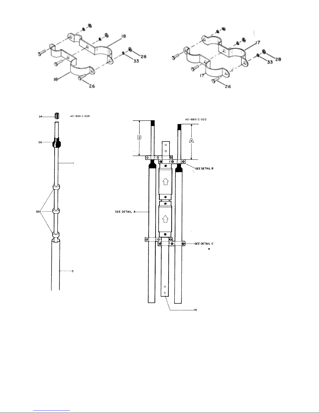
Detail B
m
N
n
N
n
y
k
11/8" x 7/16" Mast/Capacitor Clamp
Detail C
1 1/8" x 1" Mast/Capacitor Clamp
Detail A
Ite Ite
o. Descriptio
1 Tube, 7/16" x 48" 28 Nut, 10-24, hex, stainless steel
3 Tube, 1" x 45" 33 Lockwasher, #10, internal, stainless steel
14 Coil Assembl
17 Clamp, Mast/Capacitor, 11/8" x 1" 35 Insulator, 7/16" x 7/8" spacer
18 Clamp, Mast/Capacitor, 1 1/8" x 7/16" 36 Rain Cap, 1"
26 Bolt, #10-24 x 1/2", hex head, stainless steel
, 80/40 Meters 34 Caplug, 7/16" Blac
o. Descriptio
Figure 2
80/40 Meter Assembly
 Loading...