

Hy-Gain AV-640 Instruction & Assembly Manual
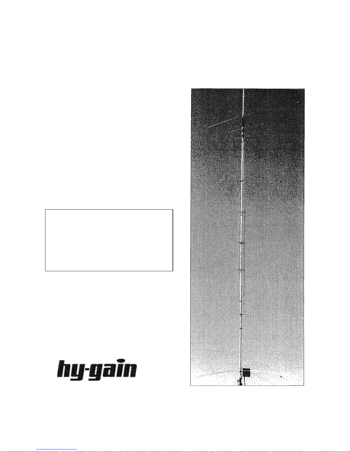
AV-640
S
C
O
y
8 Band Vertical Antenna
IN
TRU
TI
& ASSEMBLY
MANUAL
WARNING:
You can be killed if the antenna,
feedline, or the equipment used to
install the antenna accidentally
contacts utility lines. Never install
an antenna near utilit
lines.
N
308 Industrial Park Road, Starkville, MS 39759

Table of Contents
g
AV-640
Vertical Antenna
Instruction Manual
Topic
Introduction
Theory of Operation 3
AV-640 Specifications 4
Antenna Location 5
Antenna Mast 6
Antenna Groundin
Antenna Guying 6
Customer Supplied Components 6
Tools Required for Assembly 7
Safety Precautions 7
Verification of AV-640 Parts 8
Assembly Procedure 11
Installation Procedure 16
Tuning Procedure 17
Maintenance 18
Technical Assistance 18
Warranty 30
Table of Illustrations
Page
3
6
Illustration Page
Chart A 19
Chart B 19
Figure
Figure B 21
Figure C 22
Figure D 23
Figure E 24
Figure F 25
Figure G 26
Figure H 27
Figure I 28
Figure J 29
A
20
WARNING: Improper installation and assembly can be hazardous!
Read these instructions thoroughly before attempting to install or
operate this product. High power transmitting devices produce voltages
that can cause severe burns or other injuries.

Hy-Gain is proud to deliver the AV-640 Eight Band Vertical. Drawing on our
g
many years of Amateur Radio HF and VHF antenna design experience, we have
produced a well-engineered antenna capable of maximum efficiency, unmatched
performance, and superior construction.
Computer optimization of the AV-640 design yields the most efficient 3/8
wavelength electrical design with maximum gain and low angle of radiation for
long distance communication. No traps are used to achieve eight band
performance. The AV-640 is resonant on 6, 10, 12, 15 and 17 meters with
individual 3/8 wavelength radiators. The center radiator resonates on 20, 30 and
40 meters using parallel end loaded Teflon wire coils. Capacity hats on these
bands give wide 2:1 VSWR bandwidth and the antenna is kept to a height of 26
feet by the low inductance coils. There are no "tricks" or "mystery resonances"
used for impedance matching on any band.
No long-wire radials or counterpoise kits are necessary for operation of the AV-
640. The AV-640 is self contained for simple, convenient portable or fixed
operation.
Mechanical construction of the AV-640 is designed for extreme light weight and
high wind survival. Aircraft grade 6063-T832 aluminum and high strength
fiberglass are used for the entire radiator. The trap-free design presents a very
low wind surface area. Bulky tubing is not required to support unwieldy traps.
The broad 2:1 VSWR bandwidth on all bands lessens large frequency shifts
seen in other antennas when the antenna is wet or iced.
The AV-640 is covered by our Hy-Gain Warranty and supported by our customer
service team. We would like to thank you for purchasing this product from us and
ask that you let us know of any suggestion you may have. With proper assembly,
installation, and maintenance, your AV-640 will provide years of faithful service.
Theory of Operation
The AV-640 HF Multiband Vertical antenna consists of an end fed radiator that is
resonant in the 6, 10, 12, 15, 17, 20, 30 and 40 meter amateur frequency bands.
Resonances on each band are the result of impedance matching a 3/8
wavelength element with a broadband RF transformer. The characteristic
impedance at the base of the 3/8 wavelength radiator is in the order of a few
hundred ohms.
To match this impedance two tools are employed. First a counterpoise of 72"
spokes is mounted at the AV-640 base. The capacitance from this
round plane

helps lower the base impedance. Second, a 4:1 toroidal transformer (voltage
g
g
q
balun) steps the base impedance down to 50 ohms. This transformer uses (2)
ferrite cores for high power capability. Also, the windings are made of twisted
pair wire to improve coupling and reduce loss. A second high power
transformer is configured as a 1:1 current balun to help stop RF from traveling
back on the feed line s h ield. The ra d iato r of th e AV -6 40 is at DC gro und
potential for static drain. This is accomplished by a radio frequency choke in
The center radiator of the AV-640 supports 1/4 wavelength stubs for 6 , 10, 12
and 17 meters. The stubs are placed approximately one tenth of a wavelength
(electrically 1/8 wavelength) above the AV-640 base. At the top of each stub the
impedance is very high at the frequency the stub is tuned. This high impedance
stops, (chokes) RF at this point creating a resonant 3/8 wavelength radiator.
There is minimal loss using this method as compared to standard trap circuits.
Also, VSWR bandwidth is not restricted by the °Q" of trap components. On 15
meters, the center radiator is terminated with a capacity hat to form a 3/8
wavelength radiator. No stub or coil is used on 15 meters. For 20, 30 and 40
meters, a coil and capacity hat are used on each band to create a 3/8
wavelength radiator. The coils are mounted at the top of the center radiator.
These three coils are connected in parallel. Parallel connection separates each
band to allow individual band tuning and has less loss than does series
connection. A lso , t he AV-640 co ils have s ign ifica nt ly le s s los s than a s tanda rd
trap because the AV-640 capacity hats exhibit greater capacitance than a
typical trap, therefo re, less indu ctanc e is requ ired .
AV-640 Specifications
VSWR at Resonance:
Gain:
Hei
ht:
Wei
ht:
Horizontal Radiation Angle:
Vertical Radiation Ang le:
Wind Surface Area:
Wind Survival:
Less than 1.5:1 at antenna typical
3 dBi nominal
25 ft 10 in
22 lbs
360 degrees
16 degrees at 1/4 wavelength high
2.5 s
ft
80 mph
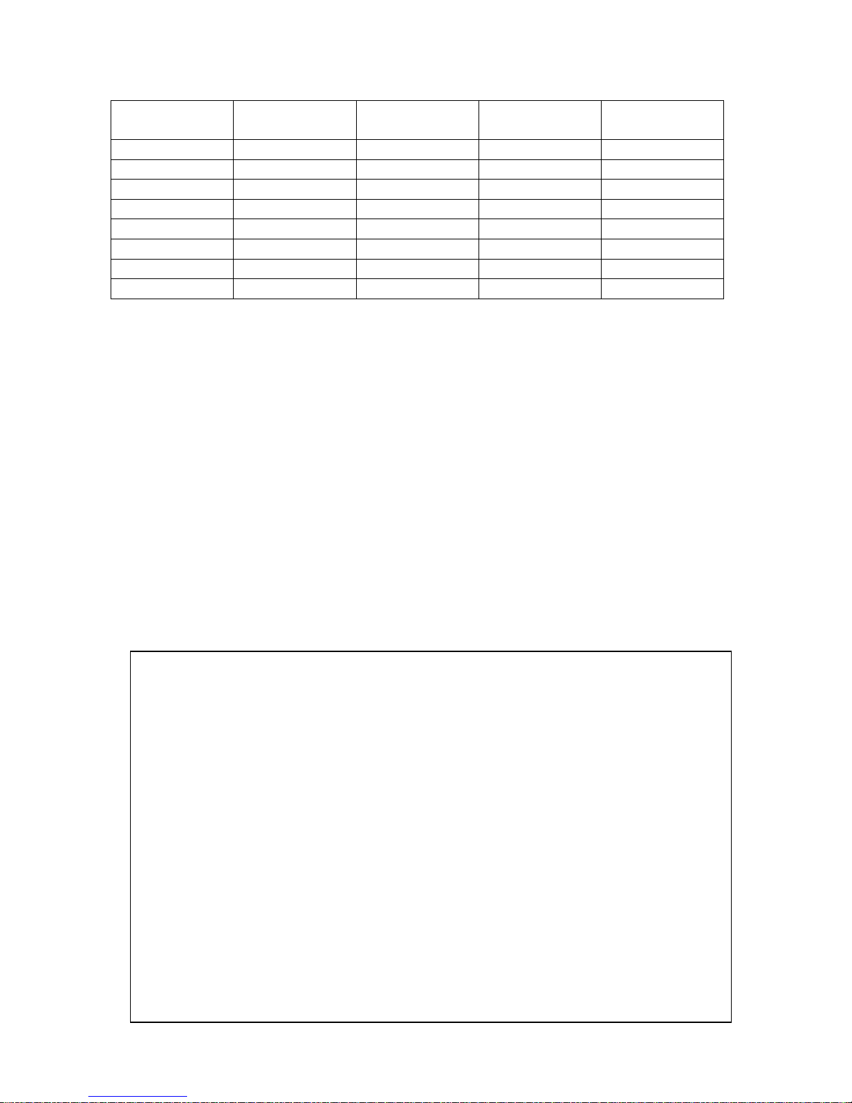
Band (m) 2:1 VSWR
(KHz)
40 150 1500 1500 500
30 175 1500 1500 500
20 500 1500 1500 500
17 500 1500 1500 500
15 500 1500 1500 500
12 500 1500 1500 500
10 1500 1500 1500 500
6 1500 300 300 100
Antenna Location
The best performance for receiving and transmitting will be obtained by mounting the
antenna in a clear location above or away from buildings, buildings, towers, feedlines,
utility wires, and other antennas. While your own ingenuity and particular circumstances
will determine the final mounting method, remember, any object within 75 Set torn the
base of the antenna can influence the performance of the AV-640.
CW
(Watts Out)
POWER SSB
(PEP Watts)
RTTY
(Watts Out)
WARNING: Always mount this antenna so that it is out of the reach
of adults as well as children and pets. The counterpoise rods can
cause injury and or seve re RF burns.
• NEVER mount this antenna in a location that will permit
unsuspecting people to come in contact wit h any part of the
antenna.
• NEVER mount this antenna where a mechanical failure might
allow the antenna, antenna support or feedline to contact power
lines or other utility wires.
• ALWAYS ground the feedline at the point where it enters a
building to a good earth ground for ligh tning protection.
• ALWAYS follow the guidelines for antenna installations as
recommended by the US Consumer Product Safety Commission.

The recommended support mast for the AV-640 is steel water pipe between the sizes of 1-
g
g
1/4" OD to 2 1/2" OD and with a length that will place the antenna base at a safe height.
Do not use thin walled conduit, aluminum tubing, or "TV" mast. The AV-640 is designed
to operate at a height of 8 or more feet for proper performance. Placement on the side of a
house or garage at eaves level is acceptable as long as the counterpoise whips will not be in
contact any snow on the roof Placement above metal roofs is acceptable if the antenna
base is at least 5 feet or more above the metal surface.
Antenna Groundin
Although the AV-640 is designed to operate efficiently without the requirement of an earth
ground, SAFETY GROUNDING must still be provided to protect equipment, property
and persons from the hazards of lightning strikes and other weather related electrical
discharges. In addition the coaxial cable feeding the antenna should have the shield
grounded to eliminate the risk of any indoor equipment failure from allowing hazardous
voltages from appearing indoors and creating a shock hazard. The support mast should be
grounded with a large diameter ground wire.
The AV-640 is DC grounded for static discharge. This is accomplished with a choke coil
in the Matching Unit. This coil could fail under high voltage spikes from a near or direct
lightning strike.
Additional protection can be accomplished by grounding the shield of the coax where it
enters the building to a good earth ground or directly burying the cable in the earth for
several feet before it enters the building. The coaxial cable should be totally disconnected
from the station during threatening weather conditions for maximum lightning
Antenna Guyin
For normal operation up to 80 mph winds, the AV-640 will not require guying. For
extreme locations such as tall building rooftops, a safety guy is recommended. Use
Dacron® rope to guy the center radiator. Attach ropes 14 feet above the antenna base.
Use care not to disturb the radiator stubs.
Customer Supplied Components
• Quality low-loss 50 ohm coax cable with PL-259 connectors
• VSWR Analyzer (MFJ-259B or equiv.) or HF transceiver with VSWR meter
• Mounting mast with required hardware to provide sturdy support

Tools Required For Assembly
• 1/4" Standard Blade Screwdriver • 7/16" Nut Driver
• #1 Phillips Screwdriver • 7/16" Open End Wrench
#2 Phillips Screwdriver • 10 nun Open End Wrench
3/8" Open End Wrench • Tape Measure 20'
3/8" Nut Driver • Safety Glasses
5/16" Nut Driver • Pliers
5/16" Open End Wrench
Safety Precaution s
WARNING: You can be killed if the antennas, feedline, or the
equipment used to install the antenna accidentally contacts any utility
lines. Never install an antenna near power lines!
• Be careful while climbing and carrying the antenna. It is heavy
enough to cause you to lose your balance if it is handled too casually
or if any part of the antenna snags on a gutter, ladder, tree, or other
item.
• Mount the antenna high enough and in the clear so th at it is out of
reach by any person or pet. Do not allow trees or other structures
near the radiator portion of the antenna. The counterpoise whips can
cause serious eye injury.
• Ensure that the mast is sturdy enough to support the weight of this
antenna including the windload of the antenna.
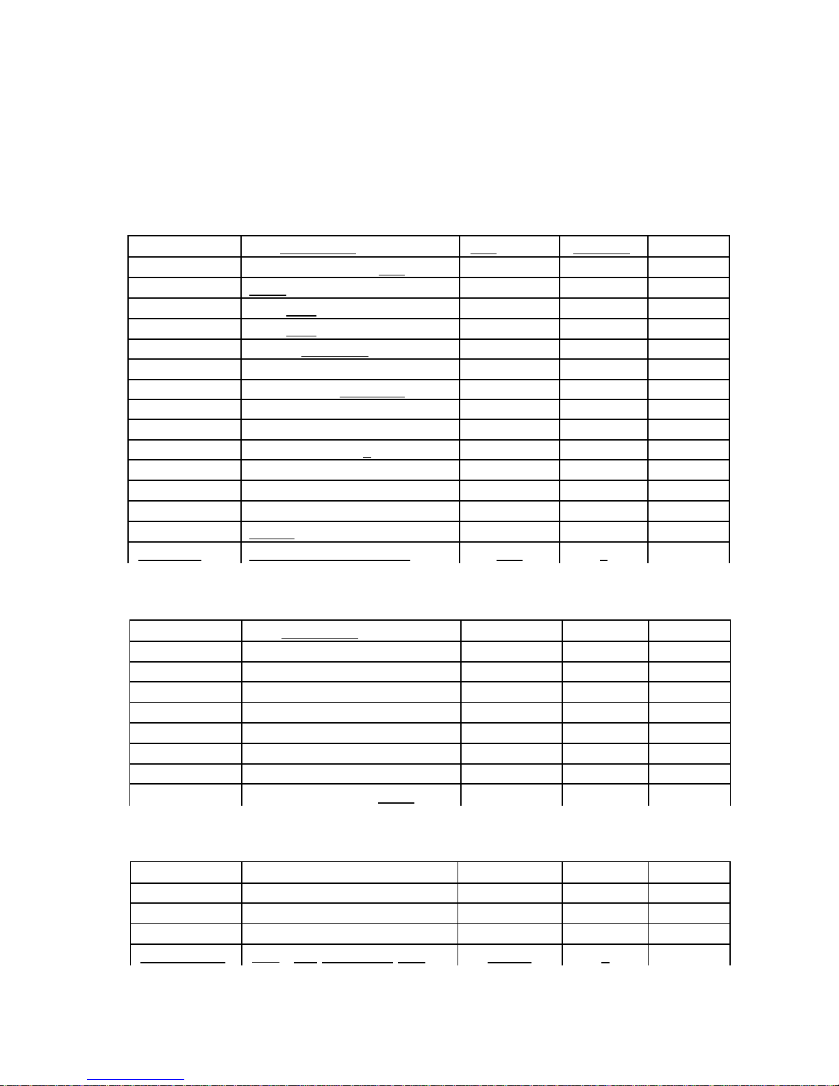
Verification of Parts
Refer to the Box Contents and Parts Bags listings below to identify all parts. Also refer to
Page 10 for drawings of the various brackets used in the AV-640. If an y part is missing
or damaged, turn to the Technical Assistance portion of this manual. There is extra
hardware supplied with the antenna. All hardware is Stainless Steel.
Part Number Part Description ED Number Quantity Received
17-AV640-4 Instruction Manual Bag IM 1
17-AV640-1 Parts Bag #1 PB1 1
17-AV640-2 Parts Bag #2 PB2 1
17-AV640-3 Parts Bag #3 PB3 1
80-AV620-1 AV640 Matching Unit MU 1
810-0620-1 Base Insulator 1 1/4" x 12" IN 1
11-0640-1 AV-640 Coil Assembly L1 1
20-AV640-1 Base Tube 1 1/2" x 12" BA 1
20-AV640-2 Radiator Section 1 1/2" x 72" BB 1
20-AV640-3 Radiator Section 13/8" x 75" BC 1
20-AV640-4 Radiator Section 1 1/4" x 75" BD I
810-0640-9 Radiator Section 5/8" x 36" BE 1
17-AV640-9 Small Tube Bundle ST 1
17-AV640-10 Spoke Bundle BS 1
738-0620 Antenna Mounting Plate AM 1
Part Number Part Description ID Number Quantity Received
810-0620-21 Stub Section 1/4" x 36" CG 1
810-0620-14 Stub Section 1/4" x 48" CF 1
810-0620-15 Stub Section 1/4" x 72" CE 3
810-0640-16 Stub Section 3/16" x 19" CA 1
810-0640-17 Stub Section 3/16" x 32" CD 1
810-0640-18 Stub Section 3/16" x 34" CC 1
810-0640-19 Stub Section 3/16" x 57" CH 1
758-2764 72" Stainless Steel Whip CW 7
Spoke Bundle
810-0640-24
1/8"
6" Aluminum Rod SP1 2
810-0640-25 1/8" 12" AluminumRod SP2 4
810-0640-26 1/8" 24" Aluminum Rod SP3 4
810-0640-27
810-0640-28
1/8"
1/8"
36" Aluminum Rod SP4 4
40" Aluminum Rod Spares 2

Parts Bag Contents
g
Instruction Manual Ba
Part Number Part Description ID Number Quantity Received
925-AV640 AV-640 Instruction Manual MN . 1
925-0006 H -Gain Warrant Card WC 1
784-1780 Warnin g La b e l WL 7
Parts Bag #1
Part Number Part Description ID Number Quanti Received
656-03755 6-32 x 3/8" Screw SS S1 48
656-05005 6-32 x 1/2" Screw SS S2 4
656-12505 6-32 x 1 1/4" Screw SS S4 10
656-1500S 6-32 x 1 1/2" Screw SS S3 6
656-1750S 6-32 x 13/4" Screw SS S5 2
705-0632S-K 6-32 Nut Keps s SS N1 71
660-0375S 10-32 x 3/8" Screw SS S6 8
711-1037S #10 Lock Washer SS W1 4
705-10325 10-32 Nut SS N2 8
705-1032SNL 10-32 Nut Nylon Insert SS N3 8
662-20005 1/4-20 x 2" Bolt SS S8 4
662-25005 1/4-20 x 2 1/2" Bolt SS S9 4
705-2520SNL 1/4-20 Nut Nylon Insert SS N5 8
745-31005 1" Hose Clam SS HC2 1
745-31505 1 1/2" Hose Clam SS HC1 3
810-0620-16 Stub Slice 3/16" x 1 1/2" SS 3
745-3108 Counterpoise Ring SS RI 2
765-1009 Plastic Ca 1/4" C1 3
765-1062 Plastic Ca 5/8" C2 1
Parts Bag #2
Part Number Part Description H) Number Quantity R ecei v ed
735-1610 Radiator Clam Bracket RB 16
758-9195 Mast Saddle MS 2
808-1786-6 Mast Plate MP 2
Parts Bag #3
Part Number Part Descri ption ID Number Quantit y Received
758-9200 2 1/2" U-Bolt Assembly SS UB 2
735-1618 Single Stub Base Bracket SB1 2
735-1611 Dual Stub Base Bracket SB2 1
737-8100 Single Stub Insulator P3 5
738-2600 90 Degree Stub Insulator P1 2
738-2602 180 Degree Stub Insulator P2 2
11-AV620-1 Jumper Wire J1 1
 Loading...