

Hy-Gain Afterburner 419 Installation & Operation Instructions
.-AFTERBURNER
ORDER NO.
419
MOBILE STATION 12V DC
BI-LATERAL LINEAR AMPLIFIER
INSTAllATION
&
OPERATION INSTRUCTIONS
AFTERBURNER
RuraI Route 3
Lincoln. Nebraska 68505
This Bi-Lateral Amplifier is precision built, compact amplifier of
advanced design. It utilizes an integrated circuit, two tubes, four
transistors and four diodes and a grounded grid, tuned plate
circuit for amplication for AM, FM, CW, and SSB signals in the
25-54 MHz range.
A special feature of the Amplifier is the automatic antenna
change over relay which operates without special external
connections making it perfect for operation with low power
transceivers not having external amplifier control circuits.
Another feature is that this unit amplifies the received signal,uti-
lizing an integrated circuit amplifier.
Variable plate tune and load capacitors offer impedance matching
for maximum output to varying antenna loads in the 40-70 ohm
range.
~The Bi-Lateral Amplifier has been designed and constructed to
suppress radiation that may cause television interference. TVI
problem has been given full consideration in design and layout of
the chassis.
There are, however, some types of TVI that cannot be prevented
within the amplifier. This is particularly true in weak signal areas.
In such cases, a good commercial low pass filter is recommended.
Height 4 1/8"
Width 7 1/8"
Depth 103/8"
Net Weight 5 Lbs.
Shipping Weight 8 Lbs.
Construction Lightweight aluminum chassis
with rugged steel case
Power Requirement +12-14V DC
15 Amp
Frequency Range 25-54 MHz
Types of Emission AM, FM, CW, SSB,DSB
Power Output (Slightly less at 50 MHZ) 220 Watts
PEP, SSB, or DSB
.~ 100 Watts (with 3.5 watts drive)
Amplification of Received Signal 20 db
Drive Requirement to Trigger Antenna Relay 1Watt
Max Drive (unmodulated carrier) 15 Watts
Odd Order Distortion Products 30 db below peak output
Harmonic Suppression 2nd Harmonic at least
35 db below peak output
Input Impedance (unbalanced) 50 Ohms
nominal, less than 2: 1 VSWR 25-54 MHz
Output Impedance (unbalanced) 50 Ohms
nominal, Adjustable 40-70 ohms, nonreactive
Antenna Switching Automatic provided by
RF sensing network
Tube and Diode Complement 2 Tubes
4 Transistors, 4 Diodes
1 Integrated Circuit
Cable Connector Data Input and Output
require MIL PL-259
() Carefully remove the amplifier from the packing carton.
EX::lmineit closely for signs of sh ipping damage. Remove the four
screws holding the top cabinet and remove all hold-down tape
and packing materials. Check to insure tubes are seated in the
sockets. Install the plate caps on the tubes and the fuse in the
holder. Inspect for any signs of internal damage.
The unit is made to operate on negative ground systems
only. Do not attempt to operate your amplifier until you have
read the manual and properly installed t he unit.
() The location is' not critical but consideration must be given to
adequate ventilation.
IMPORTANT
Allow at least 4" of clearance on all sides of the cabinet
for good air circulation.
() The primary power connection on the amplifier is the +12V
DC terminal on the rear panel.
() The fuse holder is provided on the hookup cable with a 20
amp fuse. Do not use a larger capacity fuse or amplifier,
transformer, and power supply will not be protected.
() The unit will not operate without grounding. It is
recommended that a No. 12 or heavier wire be run from the
ground terminal on the amplifier to the ground terminal on the
battery.
() The bi-Iateral amplifier will work with the common antenna
systems designed for the 25-54 MHz range provided the antenna
has a resistive input impedance between 40-70 Ohms. The SWR
should be kept to a minimum of 2:1 or less.
() The output connector provided is an So-239. For connection
of your antenna, you will need a PL-259 plug.
ON-OFF Switch Controls +12V DC power to amplifier
AM-FM & SSB Switch Adjust delay constant of automatic
antenna relay
XMT-Standby Switch .... Activates the automatic antenna relay
circu it, also supplies power to the receive
amplifier circu it.
ReceiveAmplifier ON-Off Switch Activates the integrated
circuit receive amplifier.
NOTE: Receive amplifier will only operate when theXMT-Standby.
switch is in the XMT position and the REC AMP switch is ON.
RED Indicator Light , Visual indication of applied
+12V DC power
Output Meter Visual indication of relative
RF power output.
Tune Knob Adjusts resonant frequency of amplifier.
Load Knob Adjusts coupling of output circuit to antenna.
The amplifier can be mounted either under the dash using the
bracket provided or in the trunk asdesired.
When the unit is dash mounted, a fused primary connection to
the battery or fuse block must be provided.
If tru nk mounted, a remote switch must be used, and can be
purchased through your local dealer. Mount the remote switch on
the dashwhere it isconvenient. Remote switch mounting must be
grounded to the vehicle chassis or the indicator light will be
inoperative.
Remember the front panel and remote switches are series
connected. The ampl ifier wi II not operate if either switch
is in the OFF position.
Before beginning installation, it is recommended that the
positive lead of the battery be disconnected to prevent ac-
cidental grounds and electrical system damage.
Connect the fuse hookup cable to the positive terminal of the
battery or fuse block. The other lead should run under the seats
and carpets in the protected location to the amplifier primary
power connection. A length of RG 58/U should be installed
between the transceiver and amplifier. Connect anominal 50 ohm
antenna to the amplifier.
Connect the ground stud on the amplifier to the negativebattery
connection.
Before applying power, make one final check on all wiring and
connections.
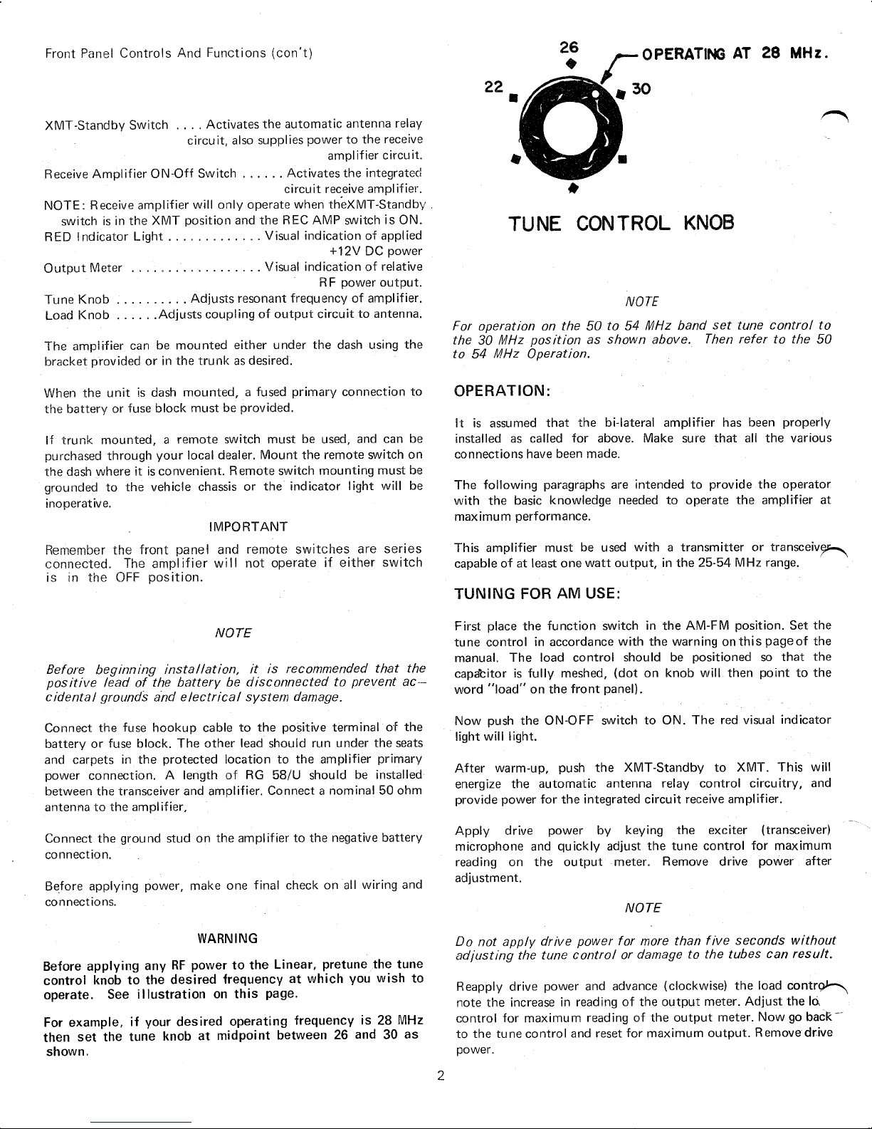
Before applying any RF power to the Linear, pretune the tune
control knob to the desired frequency at which you wish to
operate. See illustration on this page.
For example, if your desired operating frequency is 28 MHz
then set the tune knob at midpoint between 26 and 30 as
shown.
22
•
For operation on the 50 to 54 MHz band set tune control to
the 30 MHz position as shown above. Then refer to the 50
to 54 MHz Operation.
It is assumed that the bi-Iateral amplifier has been properly
installed as called for above. Make sure that all the various
connections have been made.
The following paragraphs are intended to provide the operator
with the basic knowledge needed to operate the amplifier at
maximum performance.
This amplifier must be used with a transmitter or transceiv~
capable of at least one watt output, in the 25-54 MHz range.
First place the function switch in the AM-FM position. Set the
tune control in accordance with the warning onthis pageof the
manual. The load control should be positioned so that the
capa'titor is fully meshed, (dot on knob will then point to the
word "load" on the front panel).
Now push the ON-OFF switch to ON. The red visual indicator
light will light.
After warm-up, push the XMT-Standby to XMT. This will
energize the automatic antenna relay control circuitry, and
provide power for the integrated circuit receive amplifier.
Apply drive power by keying the exciter (transceiver)
microphone and quickly adjust the tune control for maximum
reading on the output meter. Remove drive power after
adjustment.
Do not apply drive power for more than five seconds without
adjusting the tune control or damage to the tubes can result.
Reapply drive power and advance (clockwise) the load contr~
note the increase in reading of the output meter. Adjust the
hi
control for maximum reading of the output meter. Now go bacR--
to the tune control and reset for maximum output. Remove drive
power.
 Loading...