

Hy-Gain 533, CB-3 Instruction Manual
ORDER NO. 533
INSTRUCTION
MANUAL
Assembly
Instructions
Boom-to-Mast
Bracket Assembly
Element-to-Boom
Bracket Assembly
Model CB-3
CH, 3-element beam PN 805661
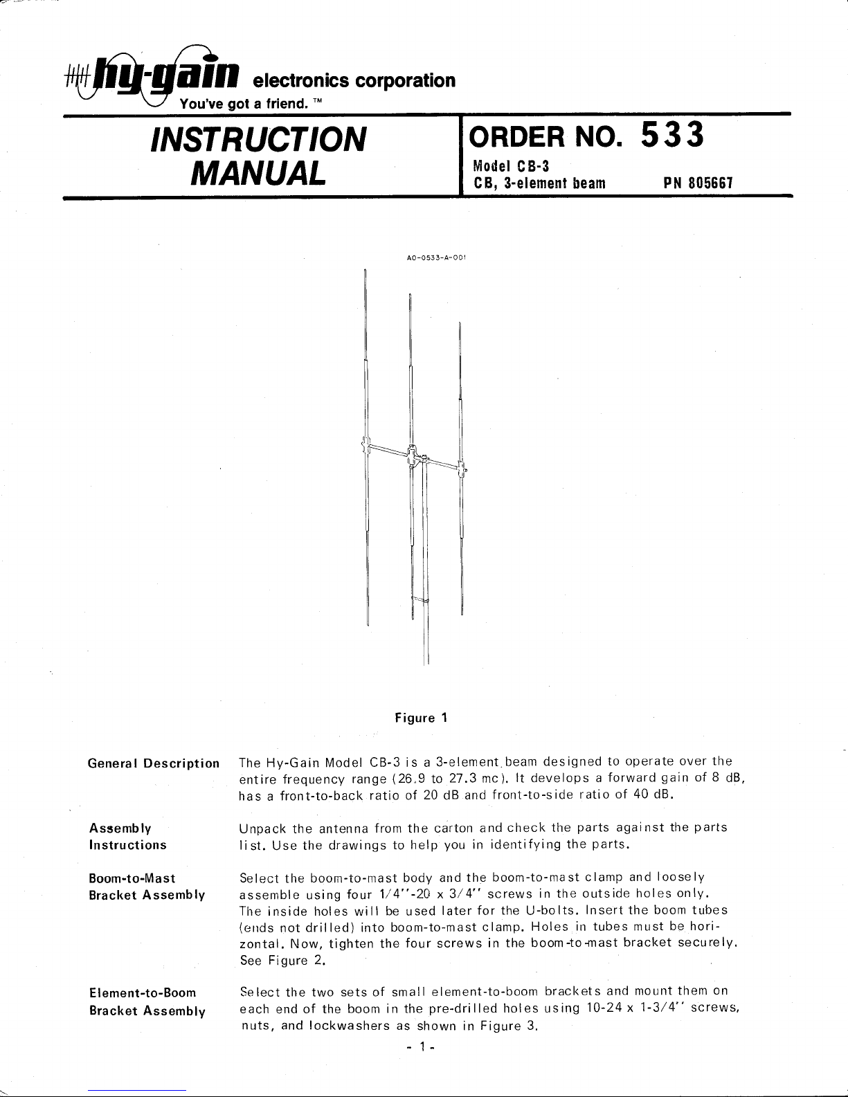
The Hy-Gain Model CB-3 is a 3-element. beam des igned to operate over the
entire frequency range (26,9 to 27.3 mc). lt develops a forward gain of 8 dB,
has a front-to-back ratio of 20 dB and front-to-side ratio of 40 dB.
Unpack the antenna from the carton and check the parts against the parts
Ii st. Use the drawings to help you in identifying the parts.
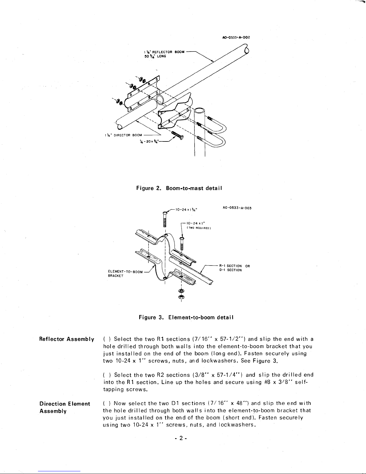
Select the boom-to-mast body and the boom-to-mast clamp and loosely
assemble using four 1/4"-20 x 3/4" screws in the outside holes only.
The inside holes will be used later for the U-bolts. Insert the boom tubes
(ends not drilled) into boom-to-mast clamp. Holes in tubes must be hori-
zontal. Now, tighten the four screws in the boom-to-mast bracket securely.
See Figure 2.
Select the two sets of small element-to-boom brackets and mount them on
each end of the boom in the pre-drilled holes using 10-24 x 1-3/4" screws,
nuts, and lockwashers as shown in Figure 3.
- 1 -
I ~." REFLECTOR BOOM
~O
'1,.'
LONG
Reflector Assembly () Select the two
Rl
sections (7/16" x 57-112") and slip the end with a
hole drilled through both walls into the element-to-boom bracket that you
just installed on the end of the boom (long end). Fasten securely using
two 10-24 x 1" screws, nuts, and lockwashers. See Figure 3.
( ) Select the two R2 sections (3/8" x 57-1/4") and slip the drilled end
into the
Rl
section. Line up the holes and secure using #8 x
3/8"
self-
tapping screws.
Direction Element
Assembly
( ) Now select the two
01
sections (7/16" x 48") and slip the end with
the hole drilled through both walls into the element-to-boom bracket that
you just installed onthe end of the boom (short end). Fasten securely
using two 10-24 x 1" screws, nuts, and lockwashers.

Driven Element
Assembly
( ) Now select the 02 sections (3/8" x 53-1/4") and slip the drilled end
into the 01 section. Line up the holes and fasten securely using #8 x 3/8"
self-tapping screws.
( ) Select the two Driven Element brackets and install a 1/4"-20 x 3/8"
anchor screw and square nut in each of the center holes as shown in
Figure 4. Do not tighten at this time.
( ) Assemble the Driven Element bracket on the reflector end of the boom
41-5/8" from the center of the reflector bracket to the center of the
Driven Element bracket as shown in Figure 5. Do not tighten the anchor
screws at this time.
( ) Select the two DE1 sections 7/16" x 58" and slip an insulator over
the undrilled end of each, then slip the insulated end into the Driven Ele-
ment bracket. Tighten the screws to hold the element securely. Tighten
the anchor screws securely.
( ) Select the DE2 sections 3/8" x 50" and note that one has a hole
drilled 1" from the end and the other has a hole drilled 2-1/2" from the
end. The tube with a hole drilled 1" from the end is for the!2..e Driven
Element and the tube with a hole drilled 2-1/2" from the end is for the
bottom Driven element.
( ) Insert the!..Q..QDE2 section (hole drilled 1" from end) into the!QQ DE1
section, align the holes and secure with a #8 x 3/8" self-tapping screw.
( ) Insert the bottom DE2 section (hole drilled 2-1/2" from end) into the
bottom DE1 section, align the holes and secure with a #8 x
3/8"
self-
tapping screw.
 Loading...