

Hy-Gain 483 Installation & Operation Instructions

ORDER NO.
483
,,-.,
'- _«()BILE
STATION BI-L1NEAR AMPLIFIER12VDC
INSTALLATION
&
OPERATION INSTRUCTIONS
HY-GAIN ELECTQONICS CORPORATION
Rural Route 3 • Lincoln. NElbraska 68505
This Bi-LinearAmplifier is precision built, compact amplifier of
advanced design. It utilizes an integrated circuit, two tubes, four
transistors and four diodes and a grounded grid, tuned plate
circuit for amplication for AM, FM, CW, and-SSB si~nals .
The Bi-Linear Ampl ifier will operate over the frequency range
25-54 MHz. However, it is F.C.C. Type Accepted under Parts 89,
91, and 93 over the frequency range 25-40 MHz.
Operation of this equipment requires a FCC license. Failure to
comply is punishable by penalties set forth in the Rules and
Regulations of the FCC. A copy of these Rules is available from
the U.S. Government Printing Office and should be in the
possessionof the operator.
The 483 Bi-LinearAmplifier complies with FCC Regulation when
shipped from the factory, and must be used with a transceiver
which is FCC Type Accepted under Parts 89, 91, and 93 for the
system to bevalid.
.,....-."
A special feature of the Amplifier is the automatic antenna
change over relay which operates without special external
connections making it perfect for operation with low power
transceivers not having external amplifier control circuits.
Another feature is that this unit amplifies the received signal,uti-
lizing an integrated circuit amplifier.
Variable plate tune and load capacitors offer impedance matching
for maximum output to varying antenna loads in the 40-70 ohm
range.
The Bi-Li near Amplifier has been designed and constructed to
suppress radiation that may cause television interference. TVI
problem has been given full consideration in design and layout of
the chassis.
There are, however, some types of TVI that cannot be prevented
within the amplifier. This is particularly true in weak signal areas.
In such cases,a good commercial low passfilter is recommended.
~e.ight 41/8"
,dth 7 1/8"
Depth . . . . . . . . . . . . . . . . . . . . . . . . . . . . . . . . . . . . . .. 103/8"
NetWeight 5 Lbs.
ShippingWeight SLbs.
Construction .•................ Lig!'ttweightaluminumchassis
with rugged steel case
Power Requirement _ +12-14V DC
15 Amp
FreRuency Range 25-54 MHz*
Types of Emission AM, FM. CW, SSB.DSB
Power Output (Slightly lessat 50 MHZ) 220 Watts
PEP,SSB,or DSB
80 Watts (with 3.5 watts drive)
Amplification of Received Signal
40
db
Drive Requirement to Trigger An>enna Relay ,1Watt
Max Drive (unmodulated carrier and FM}. _, 15 Watts
(amplitude modulated carrier) 3.5 watts
(amplitude modulated peak) .. , .. 14 watts PEP
Harmonic Supression suppressedmore than 60db
Input Impedance (unbalanced) 50 Ohms
nominal, lessthan 2: 1 VSWR25-54 MHz*
Output Impedance (unbalanced) 50 Ohms
nominal, Adjustable 40-70 ohms, nonreactive
Antenna Switching Automatic provided by
RF sensing network
Tube and Diode Complement _ 2 Tubes
4 Transistors, 10 Diodes
1 Integrated Circuit
Cable Connector Data _ Input andOutput
require MIL PL-259
*F.C.C. Type Accepted for frequency range 25-40 MHz only.
ASSEMBLY AND INSTAllATION:
() Carefully remove the amplifier from the packing car-
ton. Examine it closely for signs of shipping damage.
Check to insure tubes are seated in the sockets. Check
the plate caps on the tubes. Inspect for any signs of in-
ternal damage.
The unit is made to operate on negative ground systems
only. Do not attempt to operate your amplifier until you have
read the manual and properly installed t he unit.
() The location is not critical but consideration must be given to
adequate ventilation.
IMPORTANT
Allow at least 4" of clearance on all sides of the cabinet
for good air circulation.
() The primary pOwer connection on the amplifier is the +12V
DC terminal on the rear panel.
() The fuse holder is provided on the hookup cable .with a.2Q
amp fqse. Do not use a larger capacity fqse or amplifier,
transfqrmer, and power supplywilinotbe protected.
(). The unit. will not operCite without grounding. It
i$
recommended thClt a No.
12
or heavier wire be rqnfrom the
ground terminal on the amplifier to the ground terminal on the
battery.
() This model amplifier will work with the common antenna
systems designed for the 25-54 MHz*range provided the antenna
has a resistive input impedance between 40-70 Ohms. The SWR
should be kept to a minimum of 2:1 or less.
() The output connector provided is an So-239. For connection
of your antenna, you will need a PL 259 plug.
ON-OFF Switch Controls +12V DC power to amplifier
AM·FM&SSB Switch Adjust delay constant of automatic
antenna relay
XMT -Standby Switch .... Activ,Jfes the automatic antenna relay
circuit, also supplies power to the receive
amplifier circu it.
Receive Amplifier ON-Off Switch .. Activiltes the integratcr!
circuit receive amplifiel·.
NOTE: Receive amplifier will only operilte when th'eXMT-Standby
switch is ill the XMT position anel the REC AMP switch is ON.
RED Indicator Light Visual indication of applied
+12V DC power
Output Meter. . . . . . . . . . . . .. . .. Visual ineliciltion of relative
RF power output.
Tune Control Adjusts reson,mt frequency of amplifier.
Load Control Adjusts coupling of output circuit to antenna.
The amplifier Cdn be mounted either uncler the dilsh using the
bracket provided or ill the trunk asdesired.
When the unit is clash lTlountted,
i.I
r~lseciprimary connection to
the battery or fuse block mustlwprovided.
If trunk mOLinted, a remote switch must be uSI~d,ami can be
purchased through your local deJler. MOUllt the remote switch on
th,; dash where it iscOllVeniellt. Remote switch 1l10Llntillgmust be
grounded to the vehicle chilssis or thl~ indicator light will be
Inoperative.
R('I1~':;l1hl~1
tlH:
tront panel dnl! rl)lllo!e Oiwilclws ,lie series
conll"cWd. Tlll~ aillplifil~r Will not OPI~I'dt(' if l~i!h('r switch
is
III
till' OFF position.
Before he!llf]nln!l InstallatIOn, It IS recOIl:IlIt'ncler! that the
pas Iflve lenr! of tile hattery be dlsconm.'U,'d to f!lp\'l'nt de
eldental.wuunds and p/petrleal system dall1a.1je.
Conlwct the fuse hookup cabl,) to the positive tl'rmin,il of the
battery or fLise block. The othl~r Iedd should 1'L1numier the seats
and carpets in the protec!l;d locdtion to the dillplifil'r primary
power connection. A length of RG 58.U should
ill'
installed
between the transceiver dnd amplifier. COlll)l~Ctd 110lllilldl 50 ohm
antenna to the amplifier.
Connect the ground stud on the dmplifier to t!w IWlli.ltivehattery
connection.
Before applying power, make one final check Oil ,dl wil'ing ,1Ild
conTlections.
WARNING
WHENTHE AMPLIFIER IS USED IN THE BUSI NESS BAND, AD-
JUSTMENTS MUST BE MADE ONLY BY A FCC LICENSED
TECHNICIAN.
The 483 Bi-Linear Amplifier is factory adjusted for the rang('..-..,
25-32 MHz. Operation over the range 32-40 MHz requires,
change in the number of turns in L 1 (RF Tank Coil). A shorting
tap is placed on the end of the coil, from the left-hand side as
viewed from the front panel (seefig. 2) to the first turn, counting
from the Ieft side.
This Amplifier must be used with a transmitter or transceiver
capable of at least one watt output.
Remove Controls cover for tuning and loading.
Install knobs supplied in separate parts pack. Fully mesh
both the Tune and Load Capacitors, then install the small
knob on the Tune and the big knob on the Load capacitor
shaft, insuring that the marking on the knobs are horizontal
and pointing to the left when viewed from the front.
WARNING
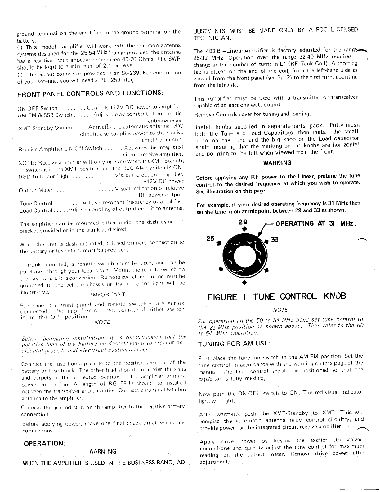
Before applying any RF power to the Linear, pretune the tune
control to the desired frequency at which you wish to operate.
Seeillustration on this page.
For example, if your desired operating frequency is 31 MHz then
set ••he tune knob at midpoint between 29 and 33 asshown.
For operation on the
50to54
MHz
band set tune control to
the29MHz position as shown above. Then refer to the
50
to 54
IV/Hz
Operation.
First place the function switch in the AM-FM position. Set the
tune contro I in accordance with the warn ing on th is page of the
mdnual. The load control shouId be positioned so that the
capabtor is fully meshed,
Now push the ON-OFF switch to ON. The red visual indicator
light will light.
After warm·up, push the XMT-Standby to XMT. This
energize the automatic antenna relay control circuitry,
provide power for the integrated circuit receive amplifier.
will
and
Apply drive power by keying the exciter (transceive"
microphone and quickly adjust the tune control for maximum
reading on the output meter. Remove drive power after
adjustment.
 Loading...