

Page 1
ORDER NO.
INSTAllATION
&
23 CHANNEL CITIZEN BAND TRANSCEIVER
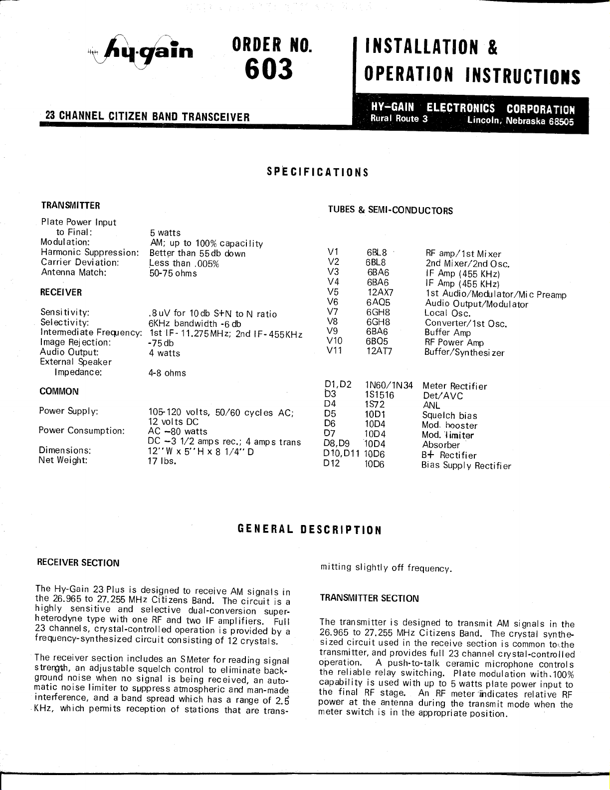
Plate Power Input
to Final:
Modulation:
Harmonic Suppression:
Carri er Oeviation:
Antenna Match:
Sensitivity:
Selectivity:
Intermediate FreQJency:
Image Rejection:
Audio Output
External Speaker
Impedance:
Dimensions:
Net Weight:
5 watts
AM; up to 100%capacility
Bett(:!rthan 55db down
Less than .005%
50-75 ohms
.8uV for 10db S+N to N ratio
6KHz bandwidth -6 db
1st IF-11.275MHz; 2nd IF-455KHz
-75 db
4 watts
105-120 volts, 50/60 cycl es AC;
12 volts DC
AC -80 watts
DC -3 1/2 amps rec.; 4 amps trans
12"W x 5"H x 81/4" 0
171bs.
603
OPERATION INSTRUCTIOIS
HY-GAIN ELECTRONICS CORPORATION
Rural Route3 Lincoln, Nebraska 68505
V1
V2
V3
V4
V5
V6
V7
V8
V9
VlO
V11
01,02 1N60/1N34
03 1S1516
04 1S72
05 1001
06 1004
07 1004
08,091004
010,011 1006
012 1006
6BL8
6BL8
6BA6
6BA6
12AX7
6A05
6GH8
6GH8
6BA6
6B05
12An
RFamp/1 st Mi xer
2nd Mixer/2nd Osc.
IF Amp (455 KHz)
IF Amp (455 KHz)
1st Audio/Mvdulator/Mic Preamp
Audio Output/Modulator
Local Osc.
Converter/1st Osc.
Buffer Amp
RFPower Amp
Buffer/Synthesi zer
Meter Rectifier
Oet/AVC
ANL
Squelch bias
Mod. hooster
Mod.Iimiter
Absorber
B+ Rectifier
Bias Supply Rectifier
The Hy-Gain 23 Plus is designed to receive AM signals in
the 26.965 to 27.255 MHz Citizens Band. The circuit is a
highly sensitive and selective dual-conversion super-
heterodyne type with one RF and two IF amplifiers. Full
23 channels, crystal-controlled operation is provided by a
frequency-synthesized circuit consisting of 12 crystals.
The receiver section includes an SMeter for reading signal
strerg~h, an adjustable squelch control to eliminate back-
ground noise when no signal is being received, an auto-
matic noise Iimiter to s~ppress atmospheric and man-made
interference, and a band spread which has a range of 2.5
KHz, which permits reception of stations that are trans-
The transmitter is designed to transmit AM signals in the
26.965 to 27.255 MHz Citizens Band. The crystal synthe-
sized circuit used in the receive section is commonto,the
transmitter, and provides full 23 channel crystal-controlled
operation. A push-to-talk ceramic microphone control s
the reliable relay switching. Plate modulation with.100%
capability is used with up to 5 watts plate power input to
the fi nal RF stage. An RF meter -jildi cates reiati ve RF
power at the antenna duri ng the transmit mode when the
meter switch is in the appropriate position.
Page 2
Select theAC power cord and attach the a-pin connector
to the a-pin connector at the rear of the unit.
coil cord into the transceivers microphone connector in
the center of the front panel. Be certain that it is secured
firmly with the knurled ring.
Always line up the key \-tay properly before pushing thft
cable connector onto the transceiver. Do not attempt to
force the connector onto the pins, when it is properly lined
up, the connector will slip on easily. Make certain the
transceiver is off (the switch is located at the extreme
counter-clockwise position of the volume control), then
insert the AC plug into the AC outlet. For protection, the
AC input to the transceiver is fused within the unit.
The antenna lead-in cable (RG-58Uor RGaU) should be
terminated with a PL~259type coaxial connector which
should then be attached to the antenna connector at the
rearof the transceiver.
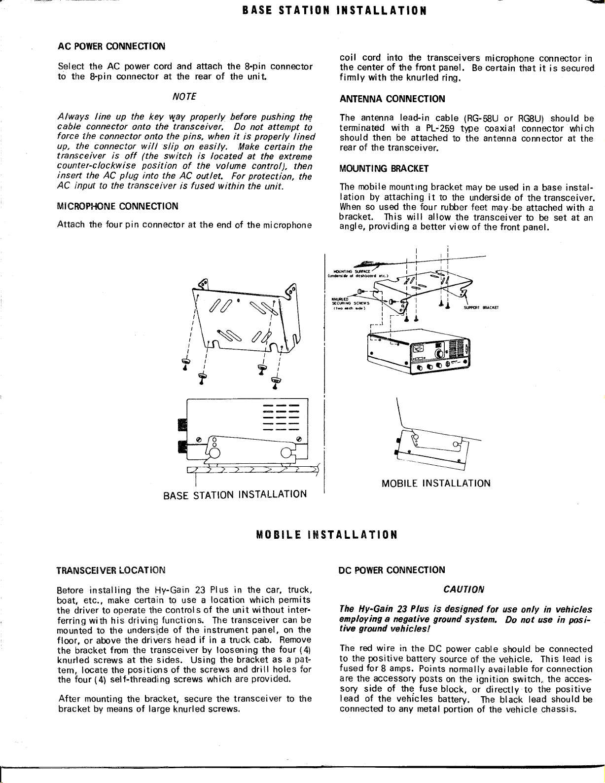
The mobile mounting bracket may be used in a base instal-
lation by attaching it to the underside of the transceiver.
Whenso used the four rubber feet may.be attached with a
bracket. This wiII all ow the transceiver to be set at an
angle, providing a better view of the front panel.
Before installing the Hy-Gain 23 Plus in the car, truck,
boat, etc., make certain to use a location which permits
the driver to operate the controls of the unit without inter-
ferring with his driving functions. The transceiver can be
mounted to the undersi.deof the instrument panel, on the
floor, or above the drivers head if in a truck cab. Remove
the bracket from the transceiver by loosening the four (4)
knurled screws at the sides. Using the bracket as a pat-
tern, locate the positions of the screws anddrill holes for
the four (4) self-threading screws which ara provided.
After mounting the bracket, secure the transceiver to the
bracket by meansof large knurled screws.
DC POWER CONNECTION
CAUTION
The Hy-Gain23Plus is designed for use only in vehicles
employinga negative ground system. Do not use in posi-
tive ground vehicles!
The red wire in the DC power cabla should be connected
to the positive battery sourceof the vehicle. This lead is
fused for a amps. Points normalIy available for connection
are the accessory posts on the ignition switch, the acces-
sory side of th~ fuse block, or directly to the positive
lead of the vehicles battery. The black lead should be
connected to any metal portion of the vehicle chassis.
Page 3
When the red and black leads have been properly connec-
ted, the 8-pin connector of the DC power cord should then
be attached to the power connector at the rear of the trans-
cei ver. AI ways line up the keyway properl y before pus h-
ing the cable connector into the transceiver. Do not
attempt to force the connector onto the pins, when pro-
perly lined up the connector will slip on easily.
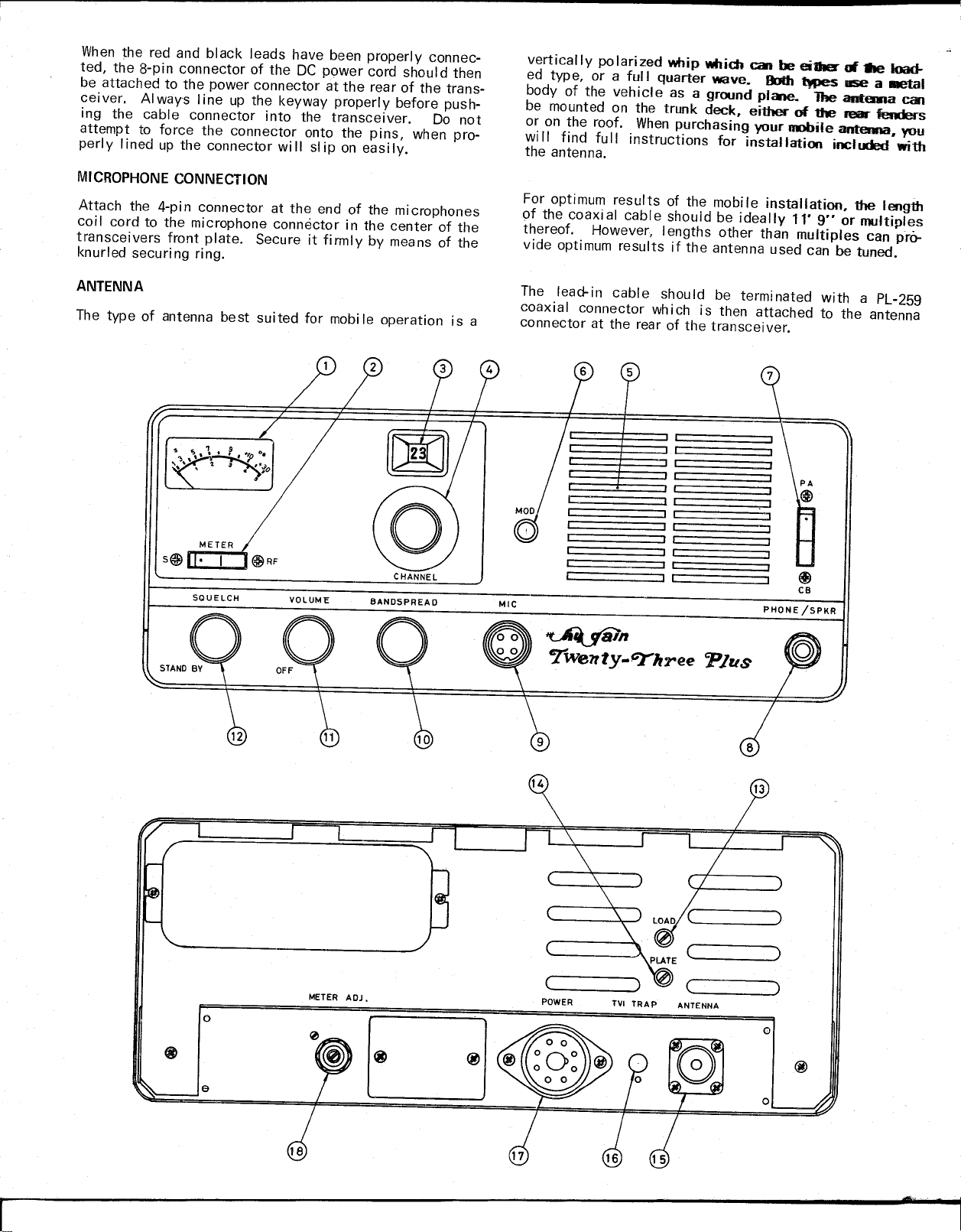
Attach the 4-pi n connector at the end of the microphones
coil cord to the microphone connector in the center of the
transceivers front plate. Secure it firmly by means of the
knurled securi ng ri ng.
vertically po larized whip which can be ei1her
ed type, or a full quarter wave.
body of the vehicle as a ground piChe. The antenna can
be mounted on the trunk deck, eithel" of tile
or on the roof. When purchasing your nmbile antenna, you
wi II find fu II instructions for installation included with
the antenna.
For optimum results of the mobile installation, the length
of the coaxi al cabl e should be ideally 11'9"or multiples
thereof. However, Iengths other than multiples can prO-
vide optimum results if the antenna used can be tuned.
The lead-in cable should be terminated with a PL-259
coaxial connector which is then attached to the antenna
connector at the rear of the transceiver.
8od1 l\!Pes
at-.e ~
use a
mar
fenders
.m.1
~ ~ r-~-_-_-_-_-_-_-_-_-_~•••.•
~n
T'we11tY-~hTee
<Plus
::J ~
CB
PHONE /SPKR
Page 4
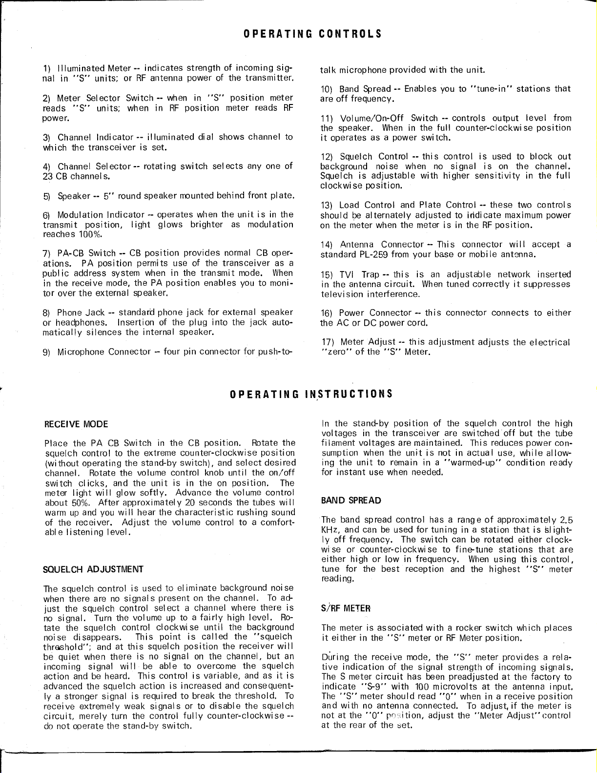
1) Illuminated Meter -- indicates strength of incoming sig-
nal in "S" units; or RF antenna power of the transmi tier.
2) Meter Selector Switch -- when in "S" position meter
reads "S" units; when in RF position meter reads RF
power.
3) Channel Indi cator -- illuminated di al shows channel to
which the transceiver is set.
4) Channel Sel ector -- rotating switch sel ects anyone of
23 CB channel s.
5) Speaker -- 5" round speaker mounted behind front plate.
6) Modulation Indicator -- operates when the unit is in the
transmit position, Iight glows brighter as modulation
reaches 100%.
7) PA-CB Switch -- CB position provides normal CB oper-
ations. PA position permits use of the transceiver as a
publ ic address system when in the transmit mode. When
in the receive mode, the PA position enables you to moni-
tor over the external speaker.
8)
Phone Jack -- standard phone jack for external speaker
or headphones. Insertion of the plug into the jack auto-
matically silences the internal speaker.
10) Band Spread -- Enables you to "tune-in" stations that
are off frequency.
11) Volume/On-Off Switch -- controls output level from
the speaker. When in the full counter-clockwi se position
it operates as a power switch.
12) Squelch Control -- this control is used to block out
background noi se when no si gnal is on the channel.
Squelch is adjustable with higher sensitivity in the full
clockwi se position.
13) Load Control and Plate Cohtrol -- these two controls
should be alternately adjusted to indicate maximum power
on the meter when the meter is in the RF position.
14) Antenna Connector -- This connector wi II accept a
standard PL-259 from your base or mobile ant8nna.
15) TVI Trap -- this is an adjustable network inserted
in the antenna circuit. When tuned correctly it suppresses
television interference.
16) Power Connector -- th is connector connects to ei ther
the AC or DC power cord.
17) Meter Adjust -- th is adjustment adjusts the el ectrical
"zero" of the "S" Meter.
Place the PA CB Switch in the CB position. Rotate the
squelch control to the extreme counter-clockwise position
(without operating the stand-by switch), and select desired
channel. Rotate the volume control knob until the on/off
switch clicks, and the unit is in the on position. The
meter Iight wi II glow softl y. Advance the vol ume control
about 50%. After approximatel y 20 seconds the tubes wi II
warm up and you will hear the characteristic rushing sound
of the receiver. Adjust the volume control to a comfort-
able listening level.
The squelch control is used to el iminate background noi se
when there are no signal s present on the channel. To ad-
just the squelch control sel ect a channel where there is
no signal. Turn the volume up to a fairly high level. Ro-
tate the squel ch control clock wi se unti I the background
noise disappears. This point is called the "squelch
thmshold"; and at this squelch position the receiver will
be quiet when there is no signal on the channel, but an
incoming signal wi II be able to overcome the squelch
action and be heard. This control is variable, and as it is
advanced the squelch action is increased and consequent-
ly a stronger signal is required to break the threshold. To
recei ve extremelyweak si gnal s or to di sabl e the squel ch
circuit, merely turn the control fully counter-clockwise--
do not operate the stand-by switch.
In the stand-by position of the squelch control the high
voltages in the transceiver are switched off but the tube
fi lament voltages are maintained. This reduces power con-
sumption when the unit is not in actual use, while allow-
ing the unit to remain in a "warmed-up" condition ready
for instant use when needed.
The band spread control has a range of approximately 2.5
KHz, and can be used for tuning in a station that is sl ight-
Iy off frequency. The switch can be rotated either clock-
wi se or counter-clockwi se to fine-tune stations that are
either high or low in frequency. When using this control,
tune for the best reception and the highest "S" meter
reading.
The meter is associated with a rocker switch which places
it either in the "S" meter or RF Meter position.
During the receive mode, the "S" meter provides a rela-
tive indication of the signal strength of incoming signals.
The S meter ci rcuit has been preadjusted at the factory to
indicate "5-9" with 100 microvolts at the antenna input,
The "S" meter should read "0" when in a receive position
and with no antenna connected. To adjust, if the meter is
not at the "0" po,;iti on, adjust the "Meter Adj ust" control
at the rear of the ::;et.
Page 5
In the transmit mode, the meter wi II read relative antenna
power output when the rocker switch is in the "RF" posi-
tion. The RF meter will read a true value only when the
transceiver is connected to a 50-ohm resistive load. If the
antenna and transmission line do not offer such a load,
the meter reading will be inaccurate.
NOTE
IT IS ILLEGAL TO OPERATE THE TRANSMITTER SECTION OF
THIS TRANSCEIVER PRIOR TO RECEIVING A VALID STA-
TION LICENSE AND CALL SIGN. PART95OF THE F.C.C.
RULES AND REGULATIONS DEALING WITH THE CITIZENS
RADIO SERVICE MUST BE OBTAINED, READ AND UNDER-
STOOD.
Provision has been made for utilizing the Hy-Gain Z3
for public address operation. For PA, Connect an
4-8 ohm speaker into the phone jack in the front af
unit. Set the "PA-CB" switch to PA, and press the
to-talk button on the microphone and talk intoitas
would when transmitting on a CB channel. Your
be heard on the external speaker; it wi II not radiate ":::
your antenna.
The phone jack may al so be used to connect a headset
normaI CB operations. When headsets are pi ugged into
the phone jack, the loud speaker is automatically silenced.
P_'S
e;c:ter.,.,a'
:'--=
;Jf~S--
'.'2'~
VOiC8il1
fe'
Be'fore using the unit to transmit, make sure that the ('PA-
CB" switch is in the CB position. Select the channel on
which you want to operate, making certain that there is no
other traffic on the channel. To transmit, simply press
the microphone button, then while holding it at approxi-
mately a 45 degree angle, speak into it at a normal voice
level. If the meter switch is in the "RF" position it wi II
indicate that you are radiating a signal. The modul ation
indicator I ight should fl icker, indicating that you are
modul ating the carrier.
When the unit is transmitting, the receiver is silent--
consequently reception is impossibl e when you are in the
transmit mode. In Iike fashion, your signal cannot be
heard by another station when it is transmitting. Each
WARNING
FCC REGULATIONS REQUIRE THAT ANV ADJUSTMENT
MADE TO THE TRANSMITTER MUST BE MADE UNDER THE
SUPERVISION OF, OR BV, A PERSON HOLDING A VALID
FIRST OR SECOND CLASS RADIO TELEPHONE OPERATOR'S
LICENSE.
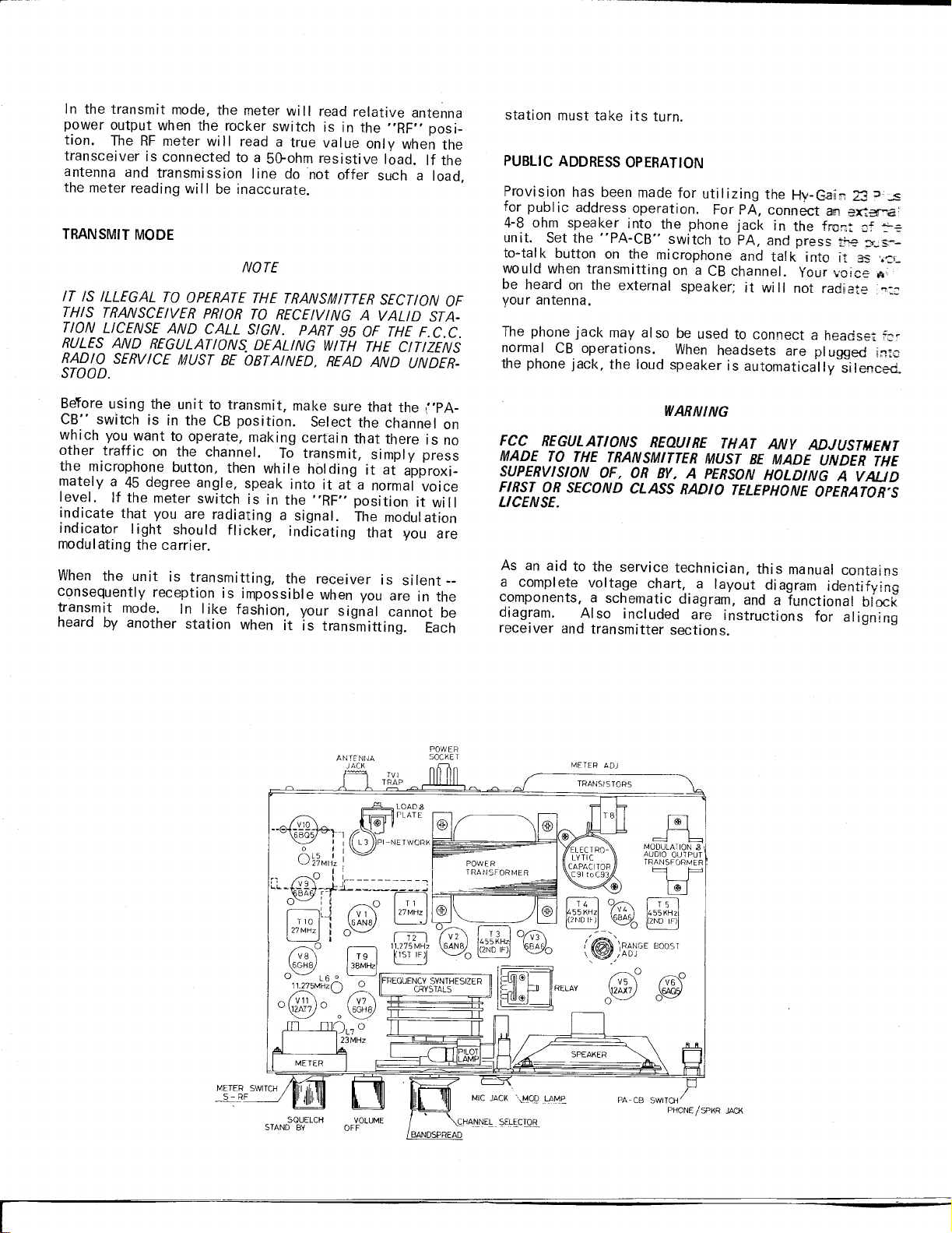
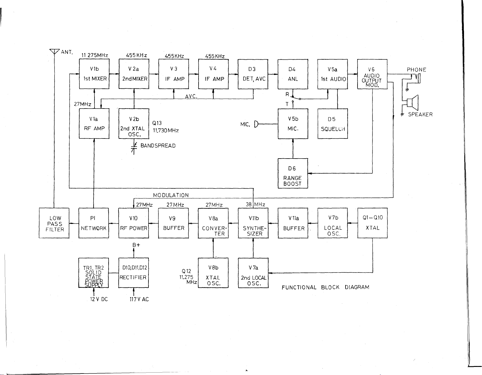
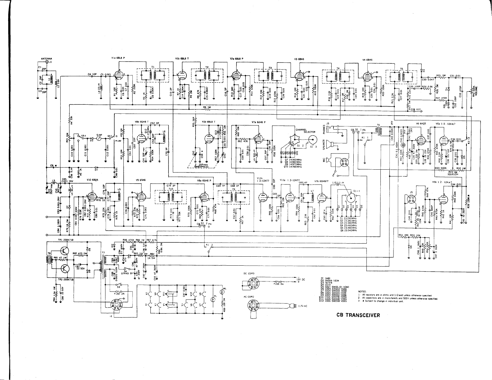
As an aid to the service technician, this manual contains
a complete voltage chart, a layout diagram identifying
components, a schematic diagram, and a functional block
diagram. Also included are instructions for al igning
receiver and transmitter sections.
d~
MODULATION
AUDIO OUTPUT
,g.
T1iF
T 5
455KHz
2ND IF)
o(jj}
PA-CB SWITCH/
PHONEISPKR JACK
Page 6
Tubes may be checked in a do-it-yourself tube tester in a
.heighborhood store, or may be taken to a·service shop for
testing. Replace any weak or defective tubes with new
ones of identical type. Before replacing tubes in the
transceiver, refer to the diagram (on"Ifollowing page)
which shows the correct tube location.
This transceiver employs a solid-state (2-transistor) power
supply circuit during 12 volts DC operation (no vibrator is
used). The transistors, which are located on the rear
panel, have been treated with a Iight protective coating to
avoid possible oxidation. Under no circumstances should
the transistors be allowed to come into contact with the
vehicle chassis, metal brackets, etc. This will cause a
short-ci rcuit and may destroy the trans istors.
There are two pilot lamps used in the transceiver. One of
these is built into the meter, and the other provides illu-
mination for the channel dial plate. Both are run consider-
ably below their maximum rating and should therefore last
almost indefinitely.
The 12-volt DC power cable uses an "in-line" fuse. The
value of this fuse is 8 amp. Provision has also been made
for fusing the primary circuit during 117 volt AC operation
by means of a 2 amp fuse located within the transceiver
(remove bottom cover for access to the fuse).
In the event of complete fai lure (tube filaments and pi lot
lamps not lighting), the fuse should always be checked
first. If it has failed, replace only with one of a similar
rating. Repeated failure of a fuse would indicate a serious
fault in the transceiver which should be investigated.
Connect the transceiver to a power source and attach the
microphone. Turn volume to its mid-pasition squelch at
minimum and the PA switch in the CB position. Set FINE
TUNING to the mid-position (normal) and the CHANNEL
selector to channel 13.
Connect an AC voltmeter (VTVM) across the speaker ter-
minals in the transceiver. Alternatively, the meter can
be connected to the '~Phone" jack by means of a standard
phone plug.
Connect a 455 KHz signal generator (modulated 30% at
1 KHz) to pin 2: of V2 (6BL8). Make certain the output
frequency of the generator is within 1 KHz of 455 KHz.
Increase generator output unti I the VTVM reads approxi-
mately 0.5 volts.
Adjust the top and bottom tuning cores of T3, T4 and T5
for maximum output. Reduce generator output progressively
as circuits come into line so that VTVM reading does not
exceed about 0.5 volts. When no further increase can be
obtained by adjusting the cores, disconnect the signal
generator and proceed with the 11.275 MHz IF adjustments.
Connect the signal generator to pin 9 of V1 (6BL8), with
the VTVM connected to ·the speaker termi naIs. Make sure
the Fine Tuning control is in the normal, center position.
Tune the generator in the vicinity of 11.275 MHz until a
maximum reading is obtained on the VTVM. Reduce gener-
ator output level unti I the meter reads about 0.5 vol ts.
Adjust top and bottom cores of T2 for maximum reading,
reducing generator output if necessary so that reading
does not exceed 0.5 volts.
The second socilIator V2B (6BL8) is crysta I-controll ed.
The Fine Tuning control permits fine tuning of the receiver
and has a total range of about 2.5 KHz. A normally func-
tioning oscillator will develop approximately -1.5 to -8
volts at pin 9 of V2B. Differences in individual crystal
activity will cause a variation in grid voltage for crystal
to crystal.
The master local oscillator, V7B, is crystal-controlled and
is used during both transmit and receive. A normally
function ing osci IIator wi II develop approxi mately -4.5
volts at pin 9 of V7B (see voltage chart). Differences in
individual crystal activity wi II cause a variation in the
voltage measured at this point.
A local oscillator is tuned as follows: adjust the bottom
core of L7 for maximum negative reading at pin 9 of V7B
with the channel selector 'SWitch set to channel 23, then
back off from peak in a clockwise direct-ion to about 70%
of the maximum reading. Check all channels for activity.
A defective crystal will produce zero voltage at pin 9 in
four consecutive channels.
After this adjustment has been made, check transmitter
output frequency to make sure it is within FCC specifica-
tion on all channels. Readjust L7 if necessary.
The synthesizer (V11B) is used during both transmit and
receive. A normally functioning oscillator will develop
approximately -0.3 volts at V7A pin 2 (see voltage chart),
Page 7
depending upon crystal activity. The output from V7 A and
the output from V7B produces a 38 MHz output in the plate
circuit of V11B, T9 being tuned to this frequency.
When it has been ascertained that all oscillators are func-
tioning normally, connect the signal generator (modulated
30% at 1 KHz) to the antenna connector. Use RG58/tJ or
equ iva lent 52 ohm cabl e. Set generator output to approxi-
mately 10 uV, and switch receiver to channel 13. Tune the
generator around 27.115 MHz until'a signal is heard in the
receiver. Adjust the generator output frequency for maxi-
mum output vol tage reading on the VTVM (at speaker
terminals). Adjust the top and bottom tuning cores of T1
for maximum output.
After receiver alignment has been completed, adjust VR1
for a "$.9" reading on the "S" meter with 100uV at the
antenna input and transceiver set to channel 13.
The detailed operation and alignment of the local oscilla-
tor and synthesizer has been covered previously. Both
osci II ators are used for the transmi t ope rat ion.
In the receive mode, B+ is removed from V8 and V9 and a
large bias is applied to the grip of the RF power output
tube V10. In the transmit mode, B+ is removed from V1,
V2, V3 and V4 in the receiver and appl ied to V8 and V9
in the transmitter. The bias formerly appl ied to V1Q is
removed.
Connect a 50 ohm dummy load to antenna connector before
proceeding (use two 100 ohm 2 watt resistors in parallel).
Connect a VTVM (with AC probe) to pin 1 of V9. With mike
button pressed, adjust T10 for maximum reading on channel
13. A reading of approximately 1.4 volts is normal. Fail-
ure to obtain any reading may indicate trouble in the
11.275 MHz converter stage. If the receiver is normal, it
is Iikely that the trouble Iies beyond T9, in which case
V8 or the 11.275 MHz crystal should be suspected. After
this adjustment has been made, check transmitter output
frequency to make sure it is within FCC specification on
all channel s. Readjust L6 if necessary.
Connect VTVM (with series resistor) to pin 2 of V10.
Adjust L5 for maximum reading on channel 13. A reading
of approximately -15 volts is normal. At this point, check
all channels with an RF wattmeter connected to the an-
tenna connector. Make sure that there is approximately
equal power output on all channels. If output is low on
some channels, slightly re-adjust L5 for equal reading on
all channel s.
CV5 (Load) and CV4 (Plate) should now be adjusted for
maximum power output on the RF wattmeter. Adjustment of
CV4 and CV5 affects the power input to the final ampl ifier.
Remember, maximum RF input power has been set at 5
watts by the FCC. Power input may be determined as
follows: Check the voltage across resistor R79 (lK, 2W) --
it should not exceed 19 volts. This figure has been ar-
rived at on the basis of an average of 223 volts on the
plate with 10 mA plate current -223 x 0.019=4.24 watts.
set CV5 fully clockwise and then peak CV4 for maximum.
Now adjust CV5 clockwise until reading of 19 volts is
measured across R79.
Connect a modulation monitor to the transceiver. Connect
the shield lead of an audio generator to a ground point on
the transceiver. Connect the "hot" center lead of the
generator in series with a .05 mfd cotidenser to pin 1 of
the microphone jack. Set generator frequency to 1 KHz
and adjust same to 4D mv output. Adjust VR4 to produce
80% modulation. To recheck the adjustment of VR4, adjust
the generator output (5mv) so that the modulation monitor
indioates 50%.
Following the above steps will produce
10rY/!;
modulation
on speech. In no case shall modulation exceed 100%.
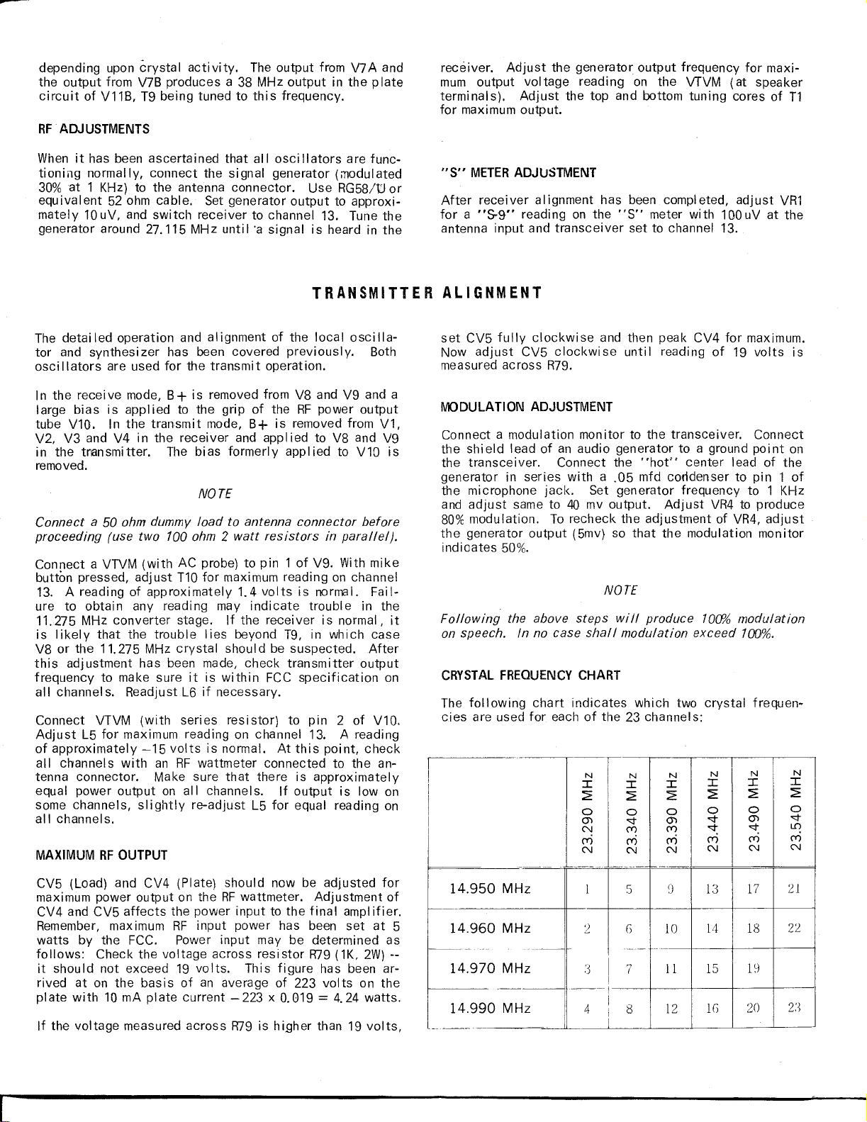
The following chart indicates which two crystal frequen-
cies are used for each of the 23 channels:
.....
-
N
N
N
~)
I
::2:
0
<::t
<::t
<Vi
N
13
14
15
IG
I
::2:
0
(J)
<::t
('f)
N
17
18
19
20
21
22
2:)
.
4.950
4.960
-~
..
~
4.970
4.990
--
MHz
MHz
MHz
MHz
N
I
~
0
(J)
N
('f)
N
1
:3
*-
4
N
I
~
0
<::t
('f)
('f)
N
5
'7
I
I
I
!
I
8
i
I
j
--
I
::2:
0
(J)
('f)
<Vi
N
10
11
12
N
I
::2:
0
<::t
l.C)
('f)
N
Page 8
This transceiver contains a built-in adjustable network in
series with the antenna. When tuned correctly, it sup-
presses television interference. This network is a filter
which offers little opposition to thetransmitter frequency
but will help eliminate the second harmonic radiation.
mlttlng location, and tune to one of the three lower TV
channels that hasa station-operating in your vicinity. If
you notice a "cross hatch" or "wavy I ine" pattern on the
screen whi Ie you are transmitting, it wi II be necessary to
adj-ust the RF network coi I slug screw (L 1) in rear of cabi-
net, to eliminate or minimize this interference. This will
usually only be necessary when the transmitter antenna is
located near the TV antenna, or that of a neighbor.
Page 9
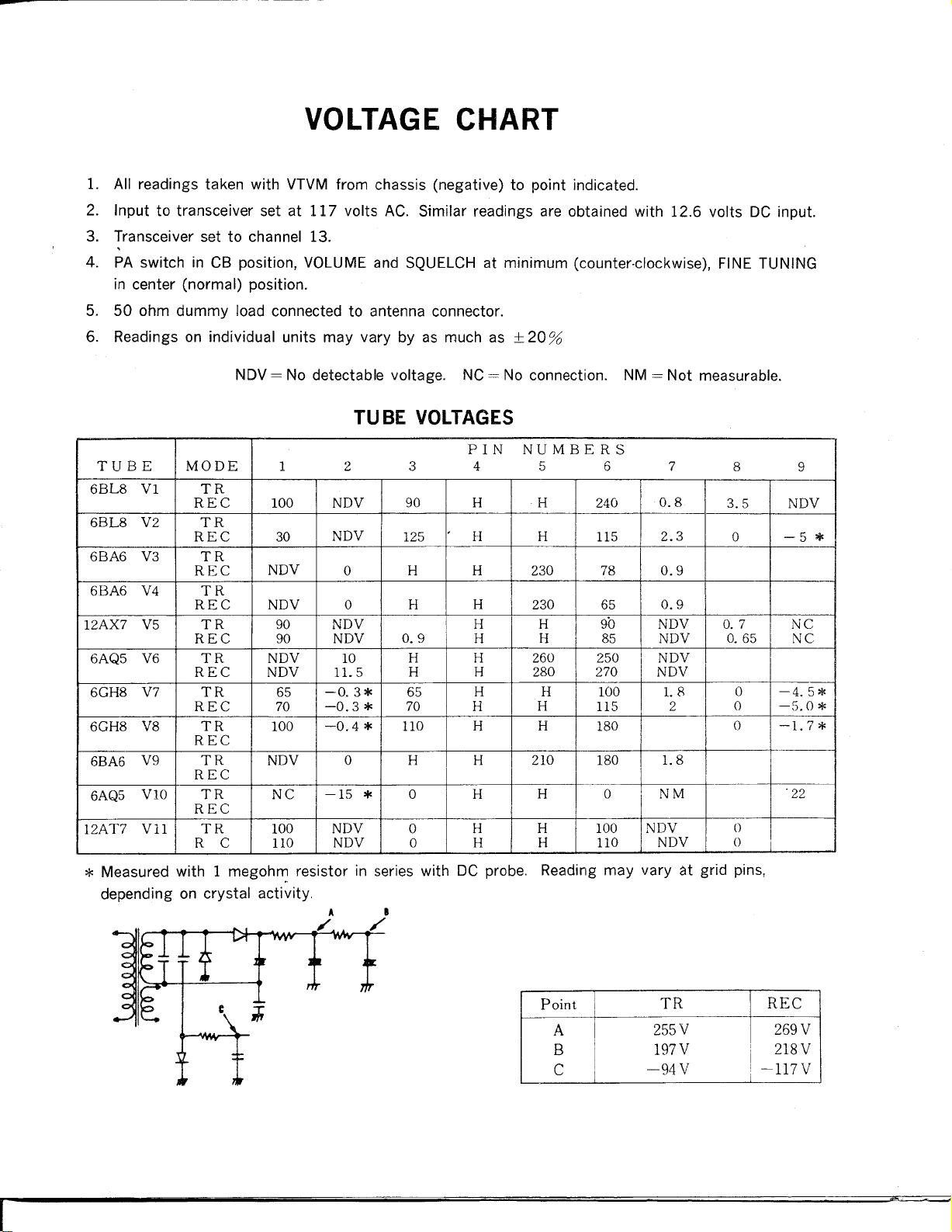
VOLTAGE CHART
1. All readings taken with VTVM from chassis (negative) to point indicated.
2. Input to transceiver set at 117 volts AC. Similar readings are obtained with 12.6 volts DC input.
3. Transceiver set to channel 13.
4. PA switch in CB position, VOLUME and SQUELCH at minimum (counter-clockwise), FINE TUNING
in center (normal) position.
5. 50 ohm dummy load connected to antenna connector.
6. Readings on individual units may vary by as much as±20 %
PIN NUMBERS
TUBE
6BL8 VI
6BL8 V2
6BA6 V3
6BA6
12AX7
6AQ5 V6
6GH8 V7
6GH8 V8 TR 100
6BA6
6AQ5
12AT7 Vll TR
MODE
TR
REC 100 NDV 90 H H
TR
REC 30
TR
REC
V4
V5 TR 90 NDV H H
V9
VlO
TR
REC NDV 0
REC
TR NDV
REC NDV
TR 65
REC 70
REC
TR
REC
TR NC
REC
R C
1
NDV
90 NDV 0.9
NDV
100
110 NDV
2
NDV
0
10
11.5
-0.3* 65
-0.3*
-0.4 *
0
-15 *
NDV
3 4 5
125
H
H
H H 260
H H
70 H
110
H H
0 H H 0 NM
0 H
0 H H 110 NDV
H H
H 230
H 230
H H
280
H H 100
H
210
6 7
240
115
78 0.9
65
90 NDV 0.7
85 NDV
250 NDV
270
H
H
H 100 NDV
115 2
180
180
0.8
NDV
2.3
0.9
1.8
1.8
8
3.5
0
0.65
0
0
0
()
()
ND~
-5*
NC
NC
-4.5*
-5.0 *
-1.7*
'22
9
I
*
Measured with 1 megoh~ resistor in series with DC probe. Reading may vary at grid pins,
depending on crystal activity.
A •
,.,
/'
Point
A
B
C
I
TR REC
255V
197V 218V
-94V
269V
-117V
Page 10
"\7
ANT.
11275MHz
455 KHz
455KHz
455KHz
LOW
PASS
FILTER
V1b
-
1st MIXER
27MHz
V1a
RF AMP 2nd XTAL
I--
PI
NETWORK RF POWER
~
~
-
V 2a
2ndMfXER
V2b
OSC.
:k
7f"
27MHz
V10
-
IF AMP IF AMP
Q13
11.730MHz
BANDSPREAO
MODULATION
27MHz
f--
V9
BUFFER
V3
I--
AVC.
f
-
V4
27MHz
vSa
CONVER-
TER
-
--
D3
DET, AVC
MIC.
38 MHz
Vllb V11a
SYNTHE- BUFFER
SIZER OSC.
-
r--
D4
ANL
Rl
T
r
V5b
MIC.
06
RANGE
BOOST
1st AUDIO
SQUELCH
-
V5a
,
05
V7b
LOCAL
-
-
V6
AUDIO
OUTPUT
MOD.
Ql-Ql0
XTAL
-
PHONE
ro
TR1, TR2
SOLID
-
~B~i~
B+
1
010,011,012
RECTIFIER
Q12
11.275
MHz
V8b
XTAL
o
Sc.
V7a
2nd LOCAL
OsC,
AL L CK DIAGRAM
I
Page 11
8
,R251M
~
~
R27470K
6
~~
~
C31 01
§
~8
II
§~
N5
~>
C300.047
"
"
~C2~11
DC CORD
---'2VDC
OiIl .
~
'"
TI~.
~
.~--+
F"U5EeA
:cJ:
117VAC
01 IN60
021N34A'IS34
03151516
041572
05 100 1"'SW05-01 ,'Y060
g~Ig8:',~~8~t~8g~
o?3t8g~~gg~~i'~8J!
OJ 1 IOD6,'5WQ5B'V06G
0121006'5W05B'Y06G
NOTES
l' All
res,stors a'e m
2 All clIpscitors are ,n m,cro·far~ds and 50CV unless otherwise specified
3: _ Su~)ecl to change In indiVidual unit.
ohms and 1/2watt unless otherwise s~lfied.
 Loading...