

Page 1

Hydro-Mix HT
Mechanical Installation Guide
To re-order quote part number:
Revision:
Revision date:
HD0766
1.2.0
June 2018
Page 2

Copyright
Neither the whole or any part of the information contained in nor the product described in this documentation may
be adapted or reproduced in any material form except with the prior written approval of Hydronix Limited,
hereinafter referred to as Hydronix.
© 2018
Hydronix Limited
7 Riverside Business Centre
Walnut Tree Close
Guildford
Surrey GU1 4UG
United Kingdom
All rights reserved
CUSTOMER RESPONSIBILITY
The customer in applying the product described in this documentation accepts that the product is a
programmable electronic system which is inherently complex and which may not be completely free of errors. In
doing so the customer therefore undertakes responsibility to ensure that the product is properly installed
commissioned operated and maintained by competent and suitably trained persons and in accordance with any
instructions or safety precautions made available or good engineering practice and to thoroughly verify the use of
the product in the particular application.
ERRORS IN DOCUMENTATION
The product described in this documentation is subject to continuous development and improvement. All
information of a technical nature and particulars of the product and its use including the information and
particulars contained in this documentation are given by Hydronix in good faith.
Hydronix welcomes comments and suggestions relating to the product and this documentation
ACKNOWLEDGEMENTS
Hydronix, Hydro-Probe, Hydro-Mix, H ydro-Skid, Hydro-View and Hydro-Control are Registered Trade Marks of
Hydronix Limited
CUSTOMER FEEDBACK
Hydronix is continually looking to improve not only its products but also the services that we offer to our
customers. If you have any suggestions about how we can do this or if you have any other feedback that would
be helpful please complete our short form at www.hydronix.com/contact/hydronix_feedback.php.
If your feedback is concerning an Atex certified product or associated service it would be very helpful for you to
give us your contact details and the model number and serial number of the product if possible. This will enable
us to contact you with any relevant safety advice should this be necessary. It is not obligatory to leave your
contact details and any information will be treated as confidential.
2 Hydro-Mix HT Mechanical Installation Guide HD0766 Rev 1.2.0
Page 3

Hydronix Offices
UK Head Office
Address: 7 Riverside Business Centre
Walnut Tree Close
Guildford
Surrey
GU1 4UG
Tel: +44 1483 468900
Fax: +44 1483 468919
Website: www.hydronix.com
North American Office
Covers North and South America, US territories, Spain and Portugal
Address: 692 West Conway Road
Suite 24, Harbor Springs
MI 47940
USA
Tel: +1 888 887 4884 (Toll Free)
+1 231 439 5000
Fax: +1 888 887 4822 (Toll Free)
+1 231 439 5001
European Office
Covers Central Europe, Russia and South Africa
Tel: +49 2563 4858
Fax: +49 2563 5016
French Office
Tel: +33 652 04 89 04
Hydro-Mix HT Mechanical Installation Guide HD0766 Rev 1.2.0 3
Page 4

4 Hydro-Mix HT Mechanical Installation Guide HD0766 Rev 1.2.0
Page 5

Revision No
Date
Description of Change
1.1.0
March 2017
First Release
1.1.1
April 2017
Minor formatting update
1.2.0
June 2018
Spacer Plate Installation Advice Added
Revision history
Hydro-Mix HT Mechanical Installation Guide HD0766 Rev 1.2.0 5
Page 6

6 Hydro-Mix HT Mechanical Installation Guide HD0766 Rev 1.2.0
Page 7

Table of Contents
Chapter 1 Hydro-Mix HT Installation ..................................................................................................... 11
1 Introduction ................................................................................................................................. 12
2 General to Flowing Material Applications ................................................................................... 12
3 General to Mixer Applicatio ns .................................................................................................... 12
4 General Mounting Advice ........................................................................................................... 13
5 Organic Material Mixers ............................................................................................................. 14
6 Screw Conveyor ......................................................................................................................... 15
7 Integration of Hydro-Mix HT in Ducting ...................................................................................... 15
8 Installing the Sensor ................................................................................................................... 17
Chapter 2 Temperature Ratings ........................................................................................................... 25
1 Process Temperature Range ..................................................................................................... 25
2 Ambient Temperature Range ..................................................................................................... 25
3 Additional Cooling ...................................................................................................................... 25
Chapter 3 Corrosion Protection............................................................................................................. 27
1 Corrosion Protection ................................................................................................................... 27
Chapter 4 Technical Specification ........................................................................................................ 29
1 Technical Specifications ............................................................................................................. 29
Appendix A Document Cross Reference .............................................................................................. 31
1 Document Cross Reference ....................................................................................................... 31
Hydro-Mix HT Mechanical Installation Guide HD0766 Rev 1.2.0 7
Page 8

8 Hydro-Mix HT Mechanical Installation Guide HD0766 Rev 1.2.0
Page 9

Table of Figures
Figure 1: The Hydro-Mix HT.................................................................................................................. 11
Figure 2: Flat Surface Installation (Fix ing Pl ate and Cla mp Ring Not Shown) ..................................... 13
Figure 3: Curved Surface Installation (Fixing Plate and Clamp Ring Not Shown) ................................ 13
Figure 4: Twin Shaft Organic Mixer Installation .................................................................................... 14
Figure 5: Single Shaft Organic Mixer Installation .................................................................................. 14
Figure 6: Screw Conveyor Installation .................................................................................................. 15
Figure 7: Screw Conveyor Mater ial Leve l ............................................................................................. 15
Figure 8: Hydronix Ducting Systems (DSAHT and DSVHT) ................................................................. 15
Figure 9: Hydro-Mix HT Integrated in a Duct ........................................................................................ 16
Figure 10: Sensor Installation (Fixi ng Pl ate Exter na lly mounted) ......................................................... 17
Figure 11: Sensor Installation (Fixing Plate Flush mounted) ................................................................ 17
Figure 12: Hydro-Mix HT Mounting Components ................................................................................. 18
Figure 13: Clamp Ring Assembled and Connected to the Fixing Plate ................................................ 19
Figure 14: Clamp Ring and Fixing Plate Attac he d to a Hydro-Mix HT ................................................. 19
Figure 15: HMHT Spacer Plates ........................................................................................................... 19
Figure 16: Clamp Ring with Spacer Plates attac h ed to the Sens or ...................................................... 20
Figure 17: Final Assembl y with Fixing Plat e Attach ed .......................................................................... 20
Figure 18: Minimum and Maximum Insertion ........................................................................................ 21
Figure 19: Measuring the Insertion Depth ............................................................................................. 21
Figure 20: Positioning the Clam p Ring ................................................................................................. 22
Figure 21: Sensor Final Position ........................................................................................................... 22
Figure 22: Flush Mounted Fixing Plate ................................................................................................. 22
Figure 23: Clamp Ring (Flush Mount) ................................................................................................... 23
Figure 24: Flush Mounted Sensor ......................................................................................................... 23
Figure 25: Temperature Profile ............................................................................................................. 25
Figure 26: Water Cooling ...................................................................................................................... 26
Figure 27: Hydro-Mix HT Installed with a Drip Loop ............................................................................. 27
Figure 28: Hydro-Mix HT with Protection Cover Installed ..................................................................... 27
Hydro-Mix HT Mechanical Installation Guide HD0766 Rev 1.2.0 9
Page 10

10 Hydro-Mix HT Mechanical Installation Guide HD0766 Rev 1.2.0
Page 11
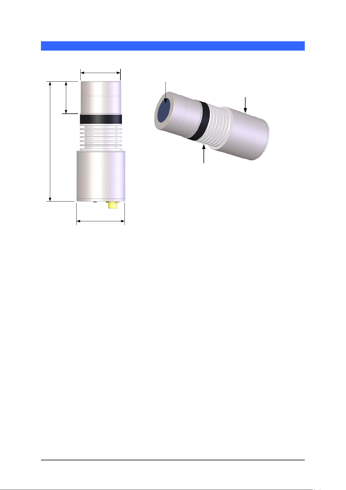
Ø 108.0mm
269.0mm
72.0mm
Ø 90.0mm
Ceramic Disc
(Sensing Area)
Hydro-Mix HT Body
(Electronics)
Cooling Fins
Packed Contents
Hydro-Mix HT Sensor
Fixing Plate
Clamp Ring
Spacer Plates (x2)
Recommended Accessories
0975A sensor Cable (4M)
Chapter 1 Hydro-Mix HT Installation
Figure 1: The Hydro-Mix HT
Available accessories:
Part No Description
4010 HMHT Fixing Plate (Supplied with sensor), Additional plates can be ordered
4020 HMHT Clamp Ring (Supplied with sensor). Additional clamps can be ordered
4030 HMHT Hydro-Mix Adapter
0975A 4m Sensor Cable
0975A-10m 10m Sensor Cable
0975A-25m 25m Sensor Cables
0116 Power Supply – 30 Watt for up to 4 sensors
0049A RS232/485 converter (DIN rail mounting)
0049B RS232/485 converter (9 pin D type to terminal block)
SIMXX USB Sensor Interface Module including cables and power supply
EAK01 Ethernet Adapter Kit including Power Supply
EPK01 Optional Ethernet Power Adapter Kit
DSAHTXX Ducting System Angled
DSVHTXX Ducting System Vertical
Hydro-Com configuration and diagnostics software is available for free to download from
www.hydronix.com
Hydro-Mix HT Mechanical Installation Guide HD0766 Rev 1.2.0 11
Page 12

Chapter 1 Hydro-Mix HT Installation
1 Introduction
The Hydro-Mix HT is a flush mounted digital m icrowa ve m oisture s ensor des igne d for measuring
in flowing organic materials. The sensor can be installed in drying, ducting, mixing, and
conveying systems and is manufactured from food safe materials
The sensor reads at 25 times per s econd, whic h enables rap id detection of changes i n moisture
content in the process, incl uding determinatio n of homogeneity in m ixing processes. T he sensor
can be easily connected to any control s ystem and m ay be configur ed remotel y when connected
to a PC using dedicated Hydron ix software. A large num ber of parameters are selectable, suc h
as the type of output and the filtering characteristics.
2 General to Flowing Materia l Applications
For accurate moistur e measurement the Hydro-Mix HT should be installed i n a location where
the material is in contact with the ceramic disc at a controlled consistent flow rate.
Follow the advice below for good sensor positioning:
• Locate the sensor where the material flows at a consistent rate.
• When installing t he se ns or in a curved surface, ens ure that the centre of t he cer a mic disc
is flush with the radius of the internal wall.
• A sampling point has to be available close to the sensor for calibration purposes.
• Avoid areas of severe turbulence in the material flow.
• Ensure the sensor is locat ed where th e m aterial is not allowe d to bu ild up o n the c er am ic
disc.
• Position the sensor away from any electrical interference (See Electrical Installation
Guide HD0678).
• Position the sensor so that it is easily accessible for routin e maintenance, adjustment an d
cleaning.
3 General to Mixer Applications
A significant benefit of the Hydronix system is that only one sensor is required in the mixer.
However, it is im portant that it is positi oned correctly in relati on to the mixer type, material and
water inlets, and other moving parts such as blades and padd les. Although paddles or scraper
blades can be a usef ul mechanism to keep the sensor free from material build up, t hey could
cause damage to an incorr ectly positi oned sensor. It will be necessary to periodicall y check the
position as the m ixer blade s, pad dles a nd flo or wear away. In all installat ions , it is recom m ended
that the sensor is fitted in an area where it is away from any possible collection of ‘sitting’ water.
As the mixer floor wears, the sensor will occasionally need to be adjusted downwards in the
mixer, to maintain the c orrect position in relation to the mixer floor. Additional ly the blades will
need to be adjusted to m aintain the eff iciency of the mixing action and cl eanlines s of the ceramic
disc.
If the sensor is allo wed to pr otrude into t he m ixer it will be suscept ible to d amage f rom the m ixer
blades/paddles as wel l as f r om abrasive materials becoming trapped b et ween t he paddles, mixer
floor and exposed side wall of the sensor.
NOTE: Damage caused under these circumstances will not be covered by warranty
For accurate and repr esentative moisture measur ement the sensor must be in c ontact with the
moving stream of m aterial. It is equ ally im portant th at no m ater ial ca n bui ld up o ver the Ceramic
Disc to obscure the sensor readings.
Follow the advice below for good sensor positioning:
• It is a good idea to provide a small inspection lid in the mixer cover, so that during mixing,
and when the mixer is empt y, the Ceram ic Disc m ay be obser ved without having to r aise
the main cover plate.
12 Hydro-Mix HT Mechanical Installation Guide HD0766 Rev 1.2.0
Page 13
Hydro-Mix HT Installation Chapter 1
Internal Surface
• Ensure that the s ensor is fitted away from the water and mater ial inlets. Particular care
should be taken in keeping the sensor clear of heavy falling objects.
• When installing t he se ns or in a curved surface, ens ure that the centre of t he cer a mic disc
is flush with the radius of the internal wall
• Avoid areas of severe turbulence. The best signal will be obtained where there is a
smooth flow of material over the sensor.
• The sensor should be positioned where it will see a continuous sample of the flowing
material and wher e the s weeping act ion of the blades ensures no b uild-up of mat erial on
the face of the sensor.
• Position the sensor away from any electrical interference (See Electrical Installation
Guide HD0678).
• Position the sensor so that it is easily accessible for r outine maintenance, adjustment an d
cleaning.
4 General Mounting Advice
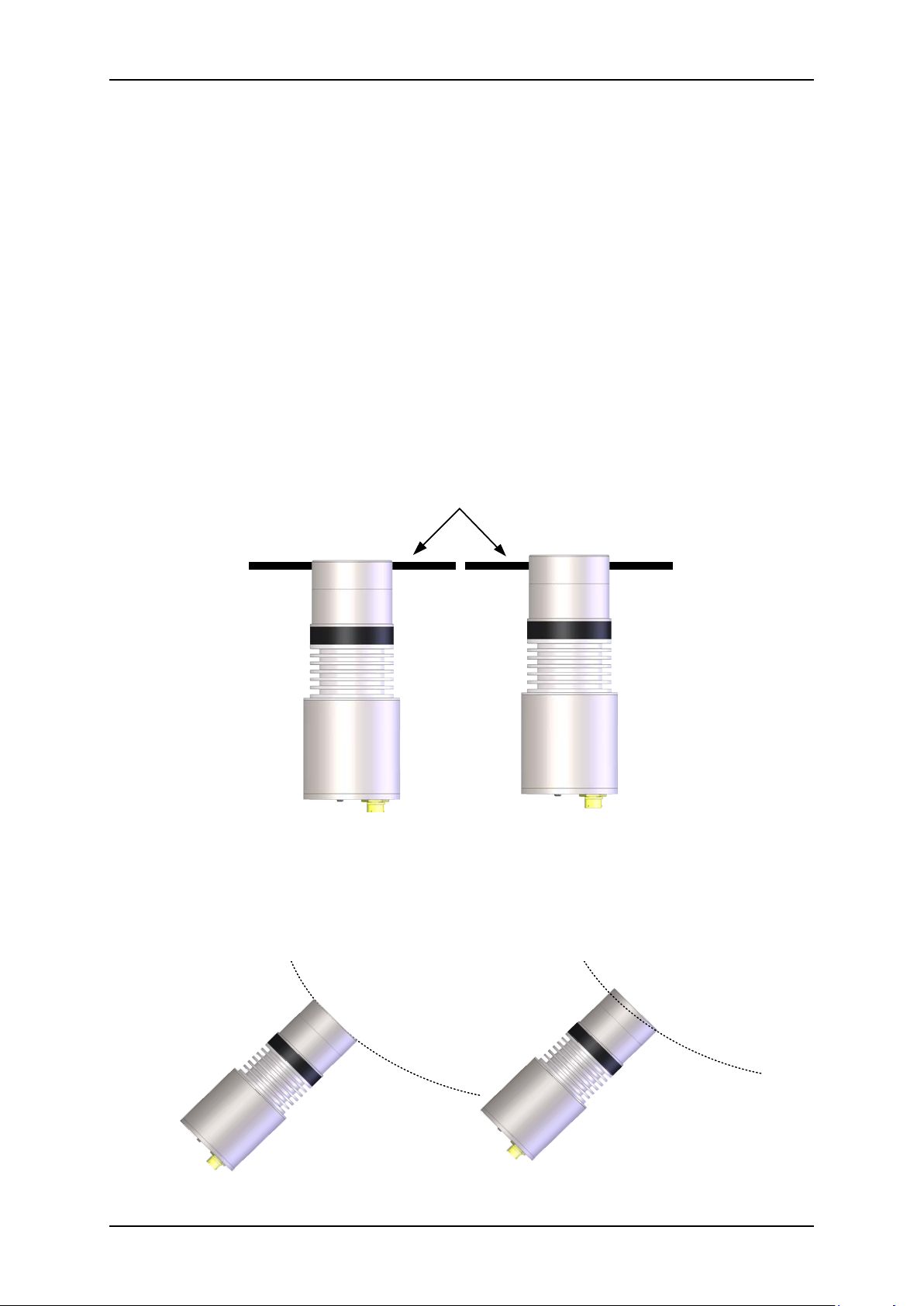
For installation in flat surfaces, the top of the sensor must be flush with the internal wall surface.
Figure 2: Flat Surface Installation (Fixing Plate and Clamp Ring Not Shown)
When installing t he sensor in a c urved surface, ensur e that the centr e of the ceram ic disc is
flush with the
radius of the internal wall
Figure 3: Curved Surface Installation (Fixing Plate and Clamp Ring Not Shown)
Hydro-Mix HT Mechanical Installation Guide HD0766 Rev 1.2.0 13
Page 14
Chapter 1 Hydro-Mix HT Installation
30.0°
5 Organic Material Mixers
When installing in a mixer it is important that the end wall scraper arm is adjusted to ensure th at
the Ceramic Dis c is kept clean to avoid material b uild up. A bu ild-up of material on the end wall
will indicate that the scraper arm is not correctly adjusted and this will affect the sensor reading.
5.1 Twin Shaft
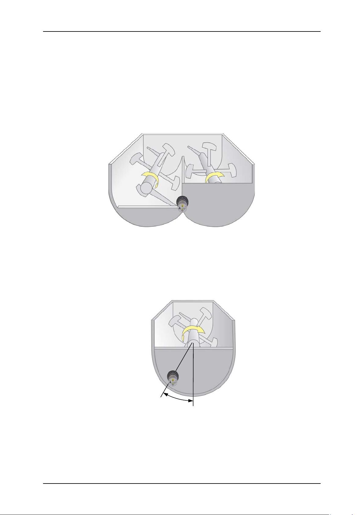
It is recommended tha t the Hydro-Mix HT should b e located in the end wall between the t wo
shafts. The sensor shoul d be located at a level lower than the shaf ts to maintain complete
coverage of the ceramic disc.
5.2 Single Shaft
Single shaft mixers should have the sensor installed in the end wall at 30° from the centre.
Figure 4: Twin Shaft Organic Mixer Installation
Figure 5: Single Shaft Organic Mixer Installation
14 Hydro-Mix HT Mechanical Installation Guide HD0766 Rev 1.2.0
Page 15
Hydro-Mix HT Installation Chapter 1
30°
150-300mm
Sampling Point
100mm
100mm
6 Screw Conveyor
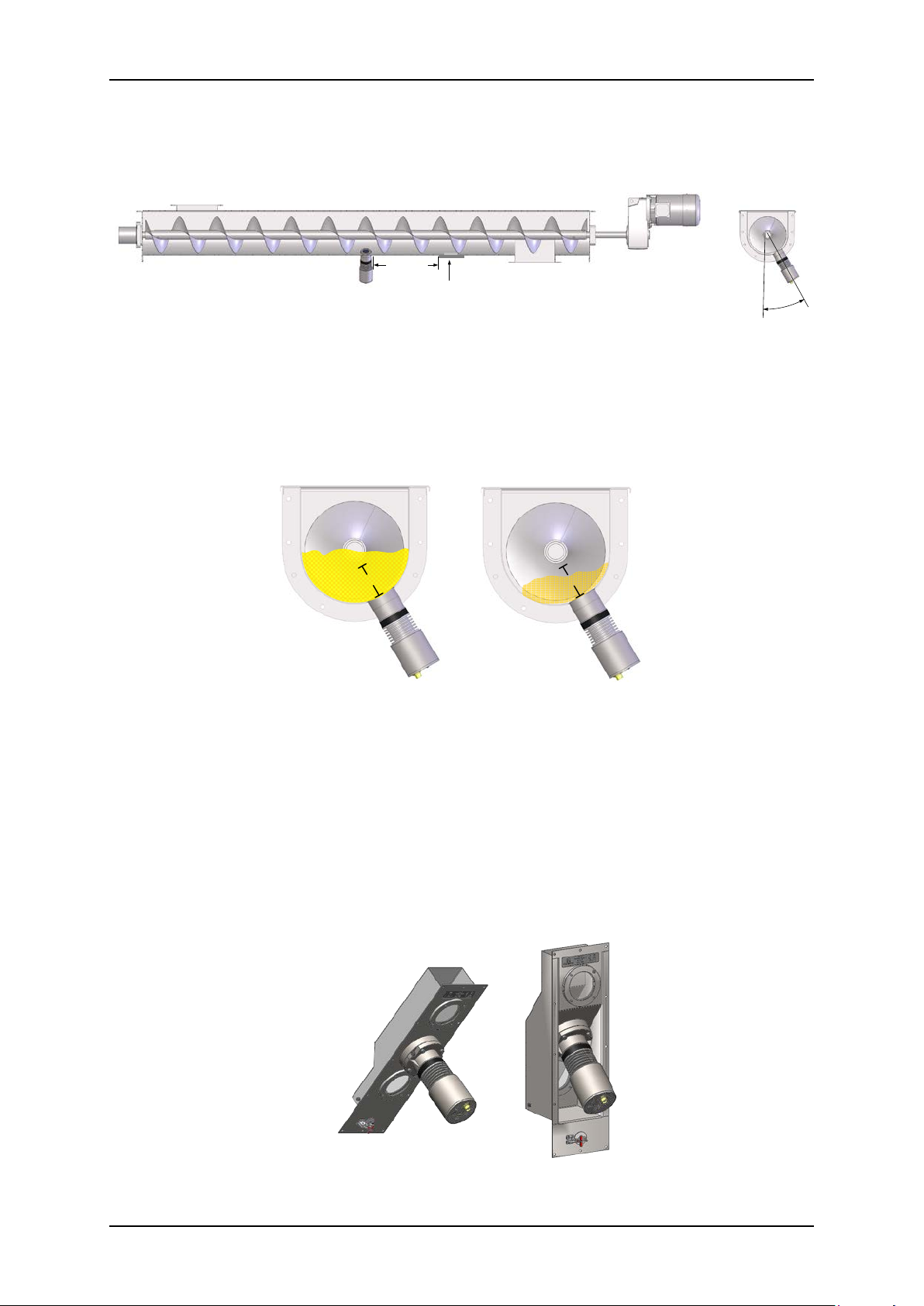
It is recommended that the sensor is installed at 30° above the base (See Figure 6).
Figure 6: Screw Conveyor Installation
It is essential that the sensor is located so that the ceramic disc is continuously covere d by at
least 100mm of material (Figure 7).
Figure 7: Screw Conveyor Material Level
7 Integration of Hydro-Mix HT in D ucting
The Hydro-Mix HT can be integrated into ducti ng. Modific ations to the duc ting might be req uired
to achieve consistent results.
Hydronix recommends the use of the Hydronix Ducting System (DSVHT or DSAHT) when
installing the Hydro-Mix HT into ducting (Figure 8) . The systems are designed for use in vert ical
(DSVHT) or angled ductin g (DSAHT). Contact Hydronix for further details about the available
ducting systems.
Figure 8: Hydronix Ducting Sy st ems (DSAHT and DSVHT)
Hydro-Mix HT Mechanical Installation Guide HD0766 Rev 1.2.0 15
Page 16
Chapter 1 Hydro-Mix HT Installation
130mm
50mm
40°
X ≥ 100mm
X
50mm
≥100mm
≥150mm
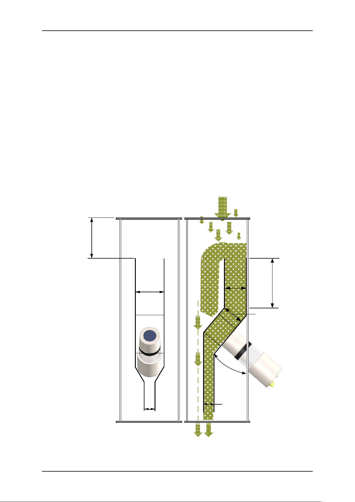
Any material in the duct must be free flowing for the sensor to be able to measure
accurately.
Best results are achieved when:-
• The sensor head is at 40º from the material flow.
• Material flow above the sensor is ducted to provide a smooth, constant flow.
• Flow rate is controlled do wn-stream of the sensor th us allowing material t o back -up over
the sensor and provide a constant material depth of at least 100mm.
• All ducting is smooth with no edges where the flow can be interrupted.
• A material flow rate of minimum 1kg/sec (3.54 ton/hour (long)) is used.
Figure 9 shows the Hydro-Mix HT integrated into a duct. The outlet dimensions will need to be
adjusted to suit each appl ication to provide a s uitable flow rate and a minimum of 100mm of
material above the sensor.
To achieve the required 10 0mm of m aterial above the sens or and a stab le flo w the H ydro-Mix
HT should be installe d in an overflow duc ting system. T his allows any add itional material not
required to mainta in 100mm in front of the sensor to overflow, re ducing the possibility of a
blockage.
16 Hydro-Mix HT Mechanical Installation Guide HD0766 Rev 1.2.0
Figure 9: Hydro-Mix HT Integrated in a Duct
Page 17
Hydro-Mix HT Installation Chapter 1
Hydro-Mix HT
M8 Screw (x4)
Clamp Ring
Fixing Plate
Weld
Weld
Wall/Floor
Ø 92-95mm Hole for Sensor Clearance
Ø 142mm Hole for Fixing Plate
Weld
Weld
Fixing Plate
Clamp Ring
Installation
Wall/Floor
Spacer Plates
(x2)
8 Installing the Sensor
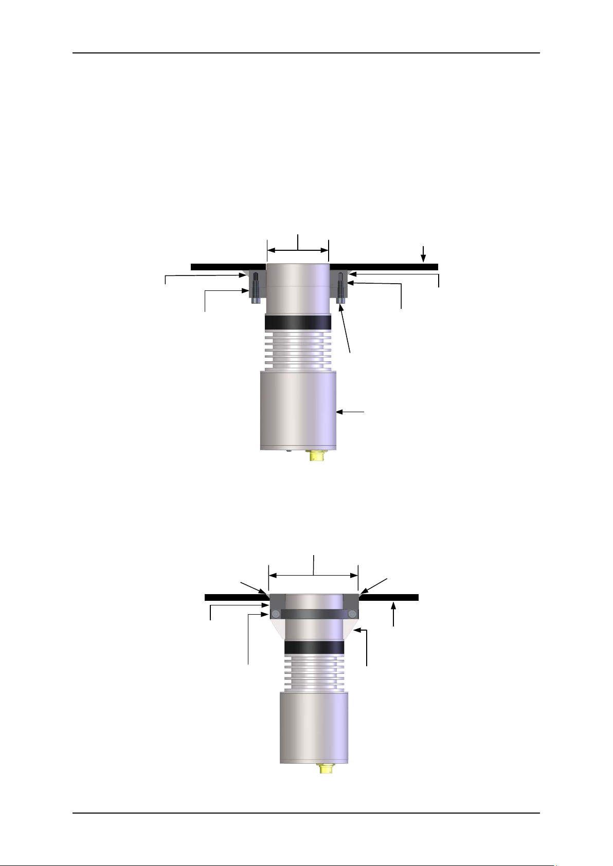
These instructions refer to installing the Hydro-Mix HT on a flat surface; all other
installation locations use the same mounting arrangement.
Each sensor is supplied with a Clamp Ring. When attached this allows the sensor to be
connected to the Fixing Plate which is welded externally or flush to the floor or wall of the
installation location.
The Clamp Ring facilitates the correct positioning and subsequent height adjustment of the
sensor.
When installing the Fixing Plate flush with the internal wall (Figure 11) the supplied Spacer Plates
can be used to ensure the sensor is correctly aligned.
Figure 10: Sensor Installation (Fixing Plate Externally mounted)
Figure 11: Sensor Installation (Fixing Plate Flush mounted)
Hydro-Mix HT Mechanical Installation Guide HD0766 Rev 1.2.0 17
Page 18
Chapter 1 Hydro-Mix HT Installation
Fixing Plate (welded
into position)
Clamp Ring
(Attached to sensor)
M8 Fixing Screws (x4)
Clamp Screws
(x2)
8.1 Cutting the Hole for the Sensor and Installing the Fixing Plate
8.1.1 Externally Mounting the Fixing Plate
Before welding the Fixing Plate to the installation location a 92-95mm diameter hole
should be cut through the external wall and any internal wear plates.
Although the outside diam eter of the sensor is 90mm it is recomme nded to cut a hole of
92-95mm diameter to allow for tolerances.
The Fixing Plate is then welded in pos ition over the hole. Ensure that t he Fixing Plate is
perpendicular to the internal wall.
During any welding operations the sensor must be removed.
8.1.2 Internally Mounting the Fixing Plate
To enable the Fixing Plate to be installed flush with the internal wall of the installation
location it is necessary to cut a 142mm hole through the external wall and any internal
wear plates. The supplied Spacer Plat es c an b e us e d to ensure that the sensor is installed
flush with the internal wall.
Depending on the insta llation requ irem ents , the Fixin g Plat e can be welded either fr om the
inside or the outside. Ensure that the Fixing Plate is flush with the internal wall.
8.2 Fitting the Clamp Ring to the Sensor (without Spacer Plates)
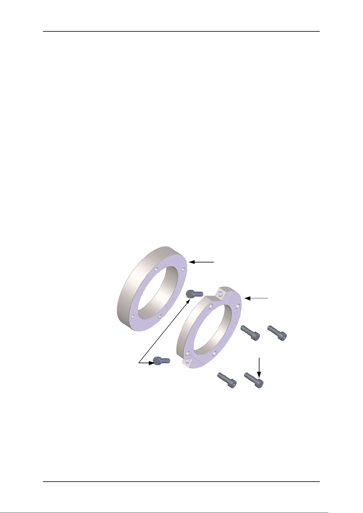
Figure 12: Hydro-Mix HT Mounting Components
18 Hydro-Mix HT Mechanical Installation Guide HD0766 Rev 1.2.0
Page 19
Hydro-Mix HT Installation Chapter 1
HMHT Spacer Plates (
x2)
Clamp Ring
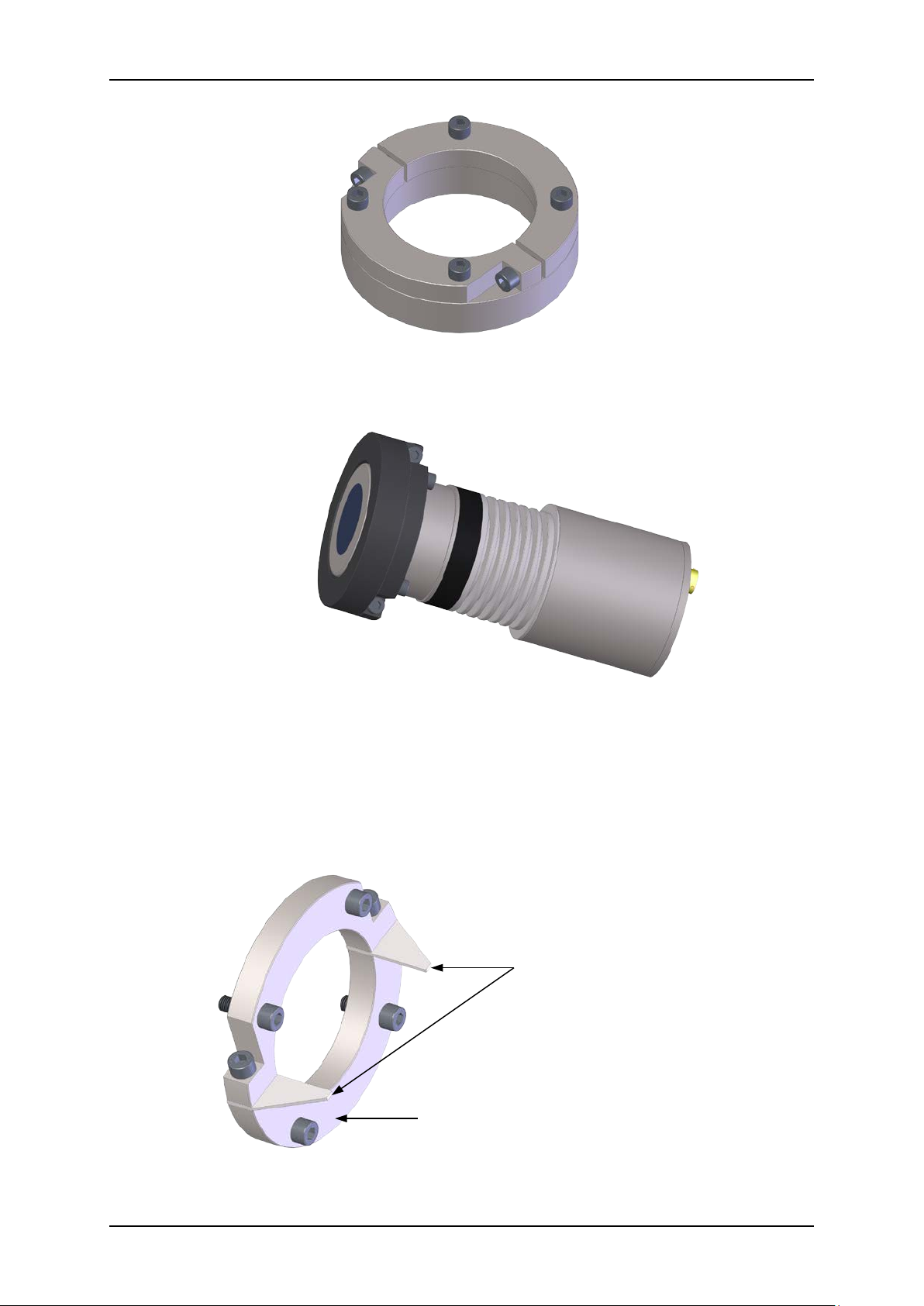
Figure 13: Clamp Ring Assembled and Connected to the Fixing Plate
Figure 14: Clamp Ring and Fixing Plate Attached to a Hydro-Mix HT
8.3 Fitting the Clamp Ring using the Spacer Plates
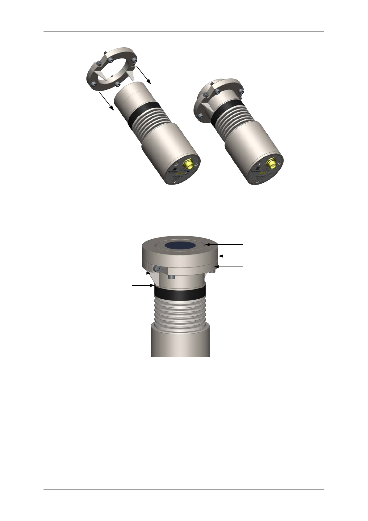
If the Fixing Plate has been installed flush with the internal wall the Spacer Plates can be
added to the Clam p Ring to assist with the installation (Figure 15). The Spacer Plates will
guarantee that the ceramic face plate is installed flush with the Fixing Plate.
Figure 15: HMHT Spacer Plates
Hydro-Mix HT Mechanical Installation Guide HD0766 Rev 1.2.0 19
Page 20
Chapter 1 Hydro-Mix HT Installation
Mounting Plate
Clamp Ring
Spacer Plate
Spacer Plate Fully Inserted
Sensor Flush with Mounting Plate
Figure 16: Clamp Ring with Spacer Plates attached to the Sensor
Figure 17: Final Assembly with Fixing Plate Attached
20 Hydro-Mix HT Mechanical Installation Guide HD0766 Rev 1.2.0
Page 21
Hydro-Mix HT Installation Chapter 1
Maximum Insertion 32 mm
Wall/Floor
Fixing Plate
X
8.4 Mounting the Sensor
NEVER HIT THE CERAMIC DISC
THE CERAMIC IS VERY HARDWEARING BUT IS BRITTLE AND WILL
CRACK IF STRUCK
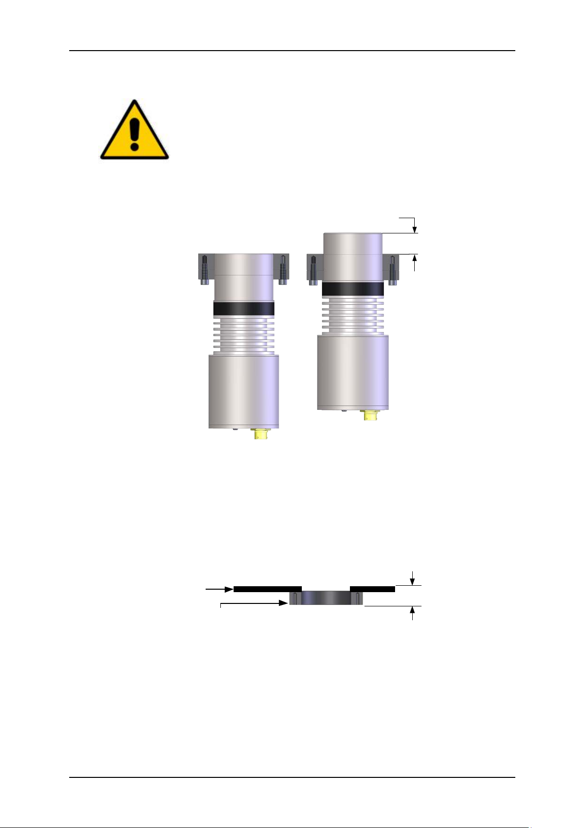
When installing th e Hydro-Mix HT it is im per ativ e th at the C er amic Face Plate is f lus h with th e
internal wall. The sensor can be adjusted by up to 32mm by adjusting the position of the
Clamp Ring (Figure 18)
Figure 18: Minimum and Maximum Insertion
8.5 Installing the Sensor on to the Fixing Plate
8.5.1 Externally Mounted Fixing Plate
1. Once the Fixing Plate has been weld ed into position over the appr opriately sized
hole, the distance from the external face of the Fixing Plate to the internal wall (x)
should be measured (Figure 19).
Figure 19: Measuring the Insertion Depth
2. Attach the Clamp Ring to the Hydro-Mix HT
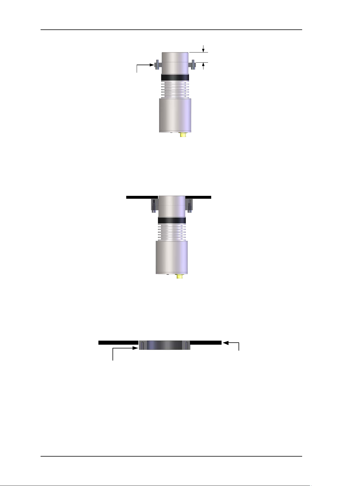
3. Adjust the position of the Clamp R ing to match the required insert ion de pth (Figure
20)
Hydro-Mix HT Mechanical Installation Guide HD0766 Rev 1.2.0 21
Page 22
Chapter 1 Hydro-Mix HT Installation
Clamp Ring
X (Max 32mm)
Fixing Plate
Wall/Floor
Figure 20: Positioning the Clamp Ring
4. Insert the sensor through the Fixing Pla t e and attach using the 4 screws.
5. Confirm that the sensor is flush with the internal wall. Adjust the Clamp Ring
position if the sensor is not flush.
Figure 21: Sensor Final Position
8.5.2 Flush Mounted Fixing Plate
1. When the Fixing Pl ate has been welded into position ensure that it is f lush with th e
internal surface (Figure 22).
Figure 22: Flush Mounted Fixing Plate
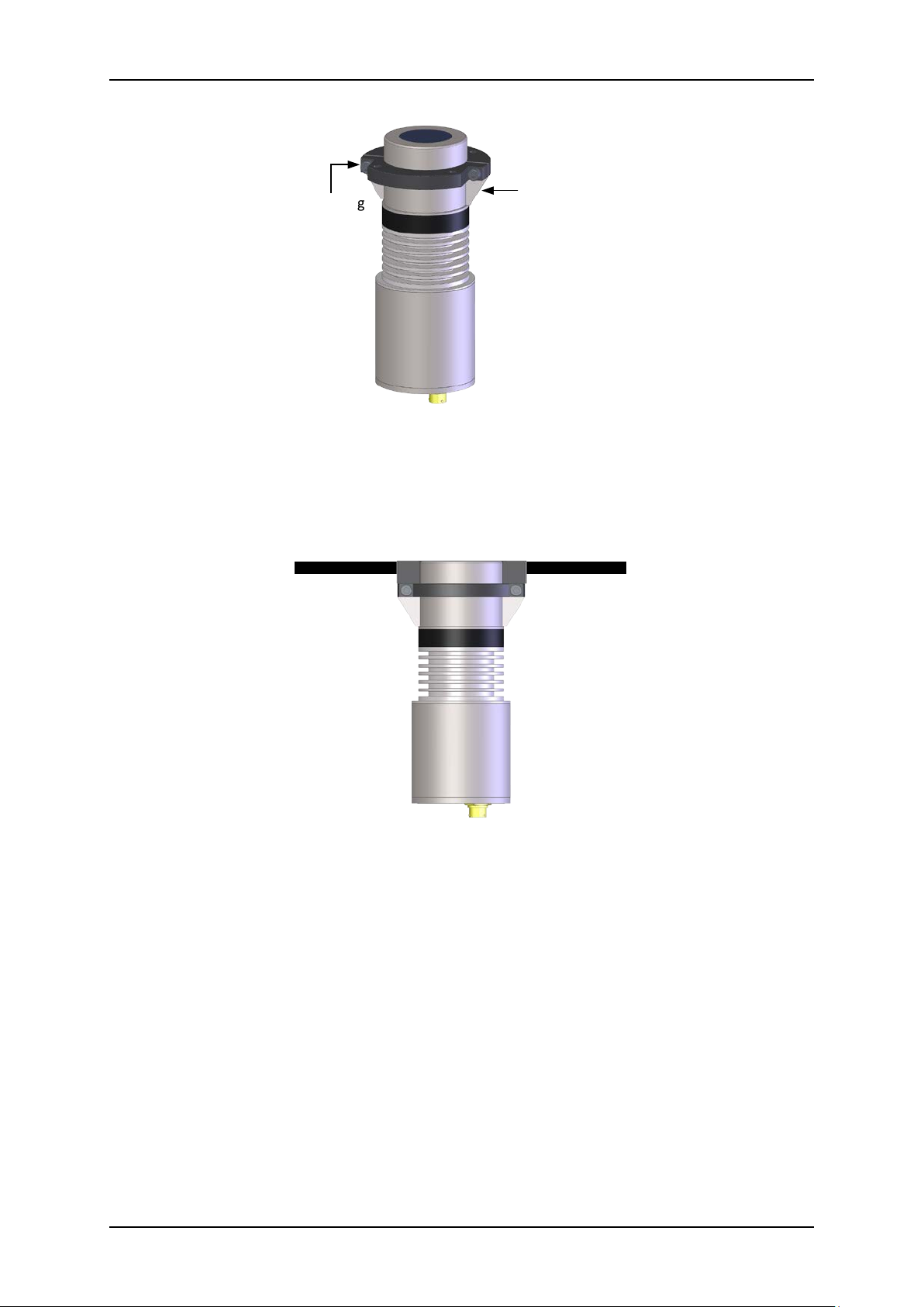
2. Attach the Clamp Ring with the Spacer Plates installed to the Hydro-Mix HT
3. Ensure the Spacer Plates are touching the ridge on the sensor (Figure 23). Tighten
the Clamp Ring Screws to lock the Clamp Ring into place
22 Hydro-Mix HT Mechanical Installation Guide HD0766 Rev 1.2.0
Page 23
Hydro-Mix HT Installation Chapter 1
Clamp Ring
Spacer Plates (x2)
Figure 23: Clamp Ring (Flush Mount)
4. Insert the sensor into the Fixing Plate and attach using the 4 M8 Fixing screws.
5. Confirm that the sensor is flush with the internal wall of the installation location
(Figure 24).
Figure 24: Flush Mounted Sensor
8.6 Removal of the Sensor
Clean out compacted material or sealant from around the sensor.
Remove the 4 Fixing Plat e screws and extract the sensor.
Warning: Do not hit the Ceramic Disc to remove the sensor.
Hydro-Mix HT Mechanical Installation Guide HD0766 Rev 1.2.0 23
Page 24

Chapter 1 Hydro-Mix HT Installation
24 Hydro-Mix HT Mechanical Installation Guide HD0766 Rev 1.2.0
Page 25
40
41
42
43
44
45
46
47
48
49
50
51
52
53
54
30 35 40 45 50 55 60 65 70 75 80 85 90 95 100 105 110 115 120 125 130 135
Ambient Temperature °C
Process Temperature °C
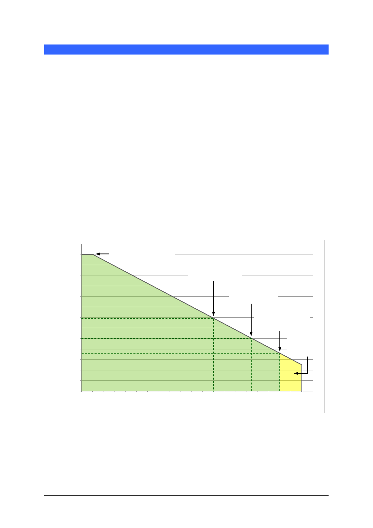
Process Temperature 90°C,
Maximum Ambient
Temperature of 47°C
Process Temperature
107°C, Maximum Ambient
Temperature of 45°
Process Temperature 120°C,
Maximum Ambient
Temperature of 43.5°C
Intermittent use
above 120°
(Maximum 10
Minutes)
Maximum Ambient Temperature
53°C. Additional Cooling required
to operate above this temperature
Chapter 2 Temperature Ratings
The maximum temperatur e r anges s tated in th is insta ll atio n gu ide ar e only valid if the Hydro-Mix H T is
installed using the supplied mounting system (Fixing Plate and Clamp Ring).
1 Process Temperature Range
The Hydro-Mix HT has been designed to o perate in a pplications wh ere the proces s temperature
is between 0-120°C. The sensor will operate at intermittent temperatures of up to 130°C to
enable cleaning to take place (maximum 10 minutes).
The Hydro-Mix HT has been designed with additional cooling fins to enable heat to dissipate
quickly. The cooling fins must not be covered and must remain clean at all times to enable
effective cooling.
Additional cooling may be required if the sensors electronics exceed 65°C.
2 Ambient Temperature Range
The ambient temperature around the sensors body will affect the overall maximum process
temperature the sens or can operate in. The maximum ambient temperature for the Hydro-M ix HT
is 53°C. However, the upper ambient temperatur e limit is reduced as the proces s temperature
increases. T he follow ing tem perature prof ile graph ind icates the m axim um process tem peratures
for a given ambient temperature (Figure 25)
Figure 25: Temperature Profile
3 Additional Cooling
If the temperature of the sensor electronics exceeds 65°C then additional cooling will be
required. Cooling can be achieved by installing a forced air s upply. The air should be directed
over the cooling fins and the sensor body.
Hydro-Mix HT Mechanical Installation Guide HD0766 Rev 1.2.0 25
Page 26
Chapter 2 Temperature Ratings
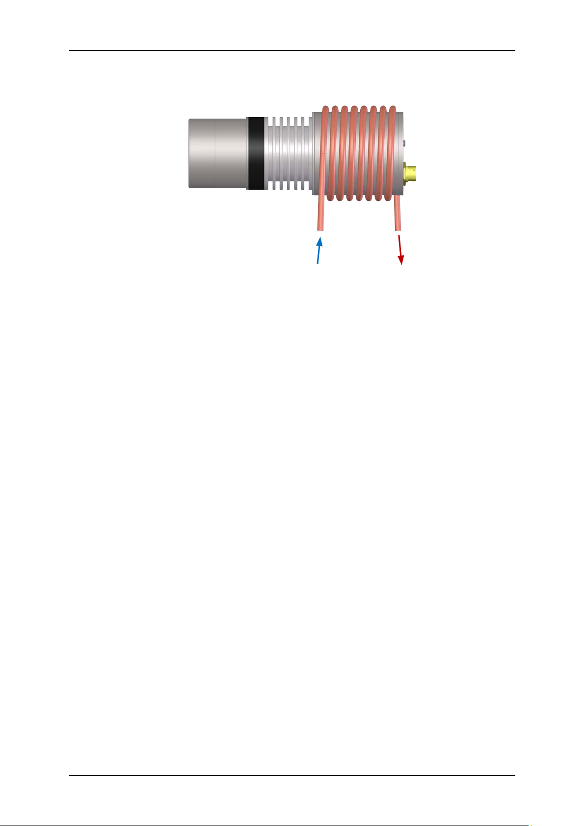
A water cooling system can also be installed using a suitable water pipe coiled around the sensor
body (Figure 26).
Figure 26: Water Cooling
26 Hydro-Mix HT Mechanical Installation Guide HD0766 Rev 1.2.0
Page 27
Installation Side Wall
Drip Loop
Hydro-Mix HT
Protection Cover
Installation Side Wall
Chapter 3 Corrosio n Protect ion
1 Corrosion Protection
In situations where corros ive materials ar e in use, ther e is potential f or the cable c onnector to be
damaged. Protection from this corrosion is possible with a few simple adjustments to how the
sensor is installed.
1.1 Sensor Position
Position the sensor so no material comes into contact with the connector.
The sensor must remain in the main flow of the material at all times to produce
accurate measurements of the moisture.
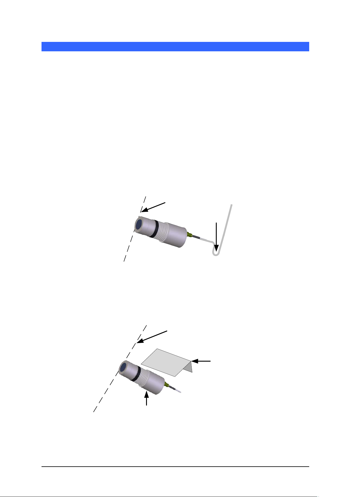
1.2 Drip Loop
Although the connector is s pec if ied to withstand water ingres s i t is rec om mended to install the
sensor with a drip loop in the cable. See (Figure 27).
Figure 27: Hydro-Mix HT Installed with a Drip Loop
1.3 Protection Cover
Install a cover over the top of the sensor to deflect the material away from the connector. (See
Figure 28). Self-amalgamating tape can also be used to seal the connector
Figure 28: Hydro-Mix HT with Protection Cover Installed
Hydro-Mix HT Mechanical Installation Guide HD0766 Rev 1.2.0 27
Page 28

Chapter 3 Corrosion Protection
28 Hydro-Mix HT Mechanical Installation Guide HD0766 Rev 1.2.0
Page 29

Chapter 4 Technical Specification
1 Technical Specifications
1.1 Dimensions
Diameter: 90mm (Sensing Head)
Length: 285mm (Including Mil Spec Connector)
Fixing: 92-95 mm Diameter Hole for sensor or 142mm Diameter hole for Fix ing Plate
1.2 Construction
Body: 316 Stainless Steel (Food Safe)
Faceplate: Ceramic (Food Safe)
O Rings: FDA Food Grade Approved
1.3 Penetration of Field
Approximately 75 -100mm dependent upon material
1.4 Range of Moisture
For bulk materials the sensor will measure up to the point of saturation.
1.5 Operating Temperature Range (Process Temperature)
0 – 120°C (32 – 248°F) continuous, up to 130°C (266°F) intermittent. The sensor will not
measure in frozen material
1.6 Power Supply Voltage
15 – 30 VDC. 1 A, minimum required for start-up (normal operating power is 4W).
1.7 Analogue Outputs
Two configurable outputs 0 – 20mA or 4 – 20mA c urrent loop outputs availabl e for moisture
and temperature. The sensor outputs may also be converted to 0 – 10 V DC.
1.8 Measurement Modes
Mode F, Mode V and Mode E
1.9 Brix Measurement Output
No
1.10 Digital (Serial) Communications
Opto-isolated RS485 2 wire port – for serial communications including changing operating
parameters and sensor diagnostics.
Hydro-Mix HT Mechanical Installation Guide HD0766 Rev 1.2.0 29
Page 30

Chapter 4 Technical Specification
1.11 Digital inputs
• One configurable digital input 15 – 30 V DC activation
• One configurable digital input/output – input specification 15 – 30 V DC, output
specification: open collector output, maximum current 500 mA (over current
protection required).
1.12 Connections
1.12.1 Sensor Cable
• Six pairs twisted (12 cores total) screened (shielded) cable with 22 AWG, 0.35mm2
conductors.
• Screen (shield): Braid with 65% minimum coverage plus aluminium/polyester foil.
• Recommended cable types: Belden 8306, Alpha 6373
• 500 Ohm resistor – The recommended resistor is an epoxy sealed precision
resistor of the following specification: 500 Ohm, 0.1% 0.33W)
• Maximum cable run: 100m, separate to any heavy equipment power cables.
1.13 Grounding
The sensor body is connected to the cable shield. Ensure equipotential bonding of all
exposed metalwork . In areas of high l igh tning r isk, correct and adequate pr otec tion should be
used.
The sensor cable s hield is connected to th e sensor body. To pr event earth loops the shiel d
must not be connected at the control panel
30 Hydro-Mix HT Mechanical Installation Guide HD0766 Rev 1.2.0
Page 31

Document Number
Title
HD0678
Hydronix Moisture Sensor Electrical Installation Guide
HD0679
Hydronix Moisture Sensor Configuration and Calibration Guide
Appendix A Document Cross Reference
1 Document Cross Reference
This section lists al l of the other doc um ents that ar e ref erred to i n this User G uide. You m ay find
it beneficial to have a copy available when reading to this guide.
Hydro-Mix HT Mechanical Installation Guide HD0766 Rev 1.2.0 31
Page 32

Appendix A Document Cross Reference
32 Hydro-Mix HT Mechanical Installation Guide HD0766 Rev 1.2.0
Page 33

Index
Ceramic
Disc Care ................................................... 21
Clamp Ring
Adjustable .................................................. 17
Fitting to Sensor ........................................ 18
Maximum Insertion .................................... 21
Corrosion Protection
Cover ......................................................... 27
Drip Loop ................................................... 27
Prevention ................................................. 27
Sensor Position ......................................... 27
Ducting
Controlled Flow Rate ................................. 16
Hydronix Ducting Systems ........................ 15
Integration in Ducting ................................ 15
Electrical Interference ................................... 13
Fixing Plate
Cutting Hole ............................................... 18
External Mounting ..................................... 18
Internal Mounting ...................................... 18
Grounding ..................................................... 30
Installation
Adjustment ................................................ 21
Advice ....................................................... 12
Orgainc Single Shaft Mixer ....................... 14
Organic Twin Shaft Mixer .......................... 14
Position ..................................................... 12
Screw Conveyor ........................................ 15
Maintenance ................................................. 12
Material
Build Up ..................................................... 12
Spacer Plates ................................................ 19
Technical Specifications ............................... 29
Temperature Ratings
Additional Cooling ..................................... 25
Ambient ..................................................... 25
Process ..................................................... 25
Hydro-Mix HT Mechanical Installation Guide HD0766 Rev 1.2.0 33
 Loading...