

Page 1
MM-KKE-M-C-U
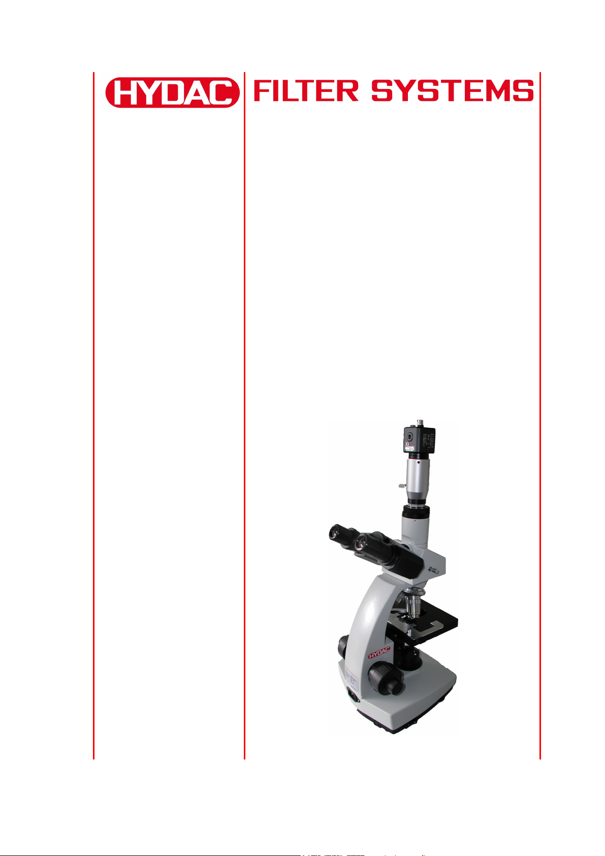
Measuring
microscope
Operating and Maintenance Instructions
English (translation of original instructions)
Document no.: 3239239b
Page 2

MM-KKE-M-C-U Trademarks
r
Trademarks
The trademarks of other companies are exclusively used for the products of those
companies.
Copyright © 2011 by HYDAC Filter Systems GmbH all rights reserved
All rights reserved. This manual may not be reproduced in part or whole without the
express written consent of HYDAC FILTER SYSTEMS GMBH. Contraventions are
liable to compensation.
Exclusion of Liability
We have made every endeavor to ensure the accuracy of the contents of this
document. However, errors cannot be ruled out. Consequently, we accept no
liability for such errors as may exist nor for any damage or loss whatsoever which
may arise as a result of such errors. The content of the manual is checked regularly.
Any corrections required will be incorporated in future editions. We welcome any
suggestions for improvements.
All details are subject to technical modifications.
Technical specifications are subject to change without notice.
HYDAC FILTER SYSTEMS GMBH
Postfach 12 51
66273 Sulzbach / Saa
Germany
Documentation Representative
Mr. Günter Harge
c/o HYDAC International GmbH, Industriegebiet, 66280 Sulzbach / Saar
Telephone: ++49 (0)6897 509 1511
Telefax: ++49 (0)6897 509 1394
E-mail: guenter.harge@hydac.com
HYDAC FILTER SYSTEMS GMBH
BeWa MM-KKE-M-C-U 3239239b en-us 2011-10-10.doc 2011-09-27
en
Page 2/32
Page 3

MM-KKE-M-C-U Content
Content
Trademarks ...............................................................................................................2
Documentation Representative...............................................................................2
Content...................................................................................................................... 3
Preface ......................................................................................................................4
Technical Support................................................................................................... 5
Modifications to the Product ...................................................................................5
Warranty ................................................................................................................. 5
Using the Documentation .......................................................................................6
Safety information and instructions....................................................................... 7
Obligations and liability ...........................................................................................7
Explanation of Symbols and Warnings, etc. ........................................................... 8
Proper/Designated Use ..........................................................................................8
Improper Use ..........................................................................................................8
Transporting the microscope.................................................................................. 9
Storing the microscope ...........................................................................................9
Checking the Scope of Delivery............................................................................ 10
Microscope features ..............................................................................................11
System requirements............................................................................................ 11
Components on the microscope...........................................................................12
Installing the microscope ...................................................................................... 16
Assembling the illuminator (cold light source) ................................................... 17
Installing and setting the camera .........................................................................19
Installing the image processing software.............................................................. 20
Operating the microscope..................................................................................... 21
Performing a measurement................................................................................... 22
Evaluating a filter membrane / sample................................................................. 23
Performing Maintenance .......................................................................................24
Cleaning / maintaining the microscope................................................................. 24
Replacing the bulb on the microscope.................................................................. 25
Replacing the illuminator bulb............................................................................... 27
Disposing of your microscope.............................................................................. 28
Model Code ............................................................................................................. 29
Technical Data ........................................................................................................30
HYDAC FILTER SYSTEMS GMBH
BeWa MM-KKE-M-C-U 3239239b en-us 2011-10-10.doc 2011-09-27
en
Page 3/32
Page 4

MM-KKE-M-C-U Preface
Preface
For you, as the owner of a product manufactured by us, we have produced this
manual, comprising the most important instructions for its operation and
maintenance.
It will acquaint you with the product and assist you in using it as intended in an
optimal manner.
Keep it in the vicinity of the product so it is always available.
Note that the information on the unit's engineering contained in the documentation
was that available at the time of publication.There may be deviations in technical
details, figures, and dimensions as a result.
If you discover errors while reading the documentation or have additional comments
or suggestions, contact us at:
HYDAC FILTER SYSTEMS GMBH
Technische Dokumentation
Postfach 12 51
66273 Sulzbach / Saar
Germany
We look forward to receiving your input.
“Putting experience into practice”
HYDAC FILTER SYSTEMS GMBH
BeWa MM-KKE-M-C-U 3239239b en-us 2011-10-10.doc 2011-09-27
en
Page 4/32
Page 5

MM-KKE-M-C-U Preface
Technical Support
If you have any questions, suggestions, or encounter any problems of a technical
nature, please don't hesitate to contact us. When contacting us, please always
include the model/type designation, serial no. and part-no. of the product:
Fax: ++49 (0) 6897 / 509 - 846
E-mail: filtersystems@hydac.com
Modifications to the Product
We would like to point out that changes to the product (e.g. purchasing options, etc.)
may result in the information in the operating instructions no longer being completely
accurate or sufficient.
After modification or repair work that affects the safety of the product has been
carried out on components, the product may not be returned to operation until it has
been checked and released by a HYDAC technician.
Please notify us immediately of any modifications made to the product whether by
you or a third party.
Warranty
For the warranty provided by us, please refer to the General Terms of Sale and
Delivery of HYDAC FILTER SYSTEMS GmbH.
They are available at: www.hydac.com -> Legal information.
HYDAC FILTER SYSTEMS GMBH
BeWa MM-KKE-M-C-U 3239239b en-us 2011-10-10.doc 2011-09-27
en
Page 5/32
Page 6
MM-KKE-M-C-U Preface
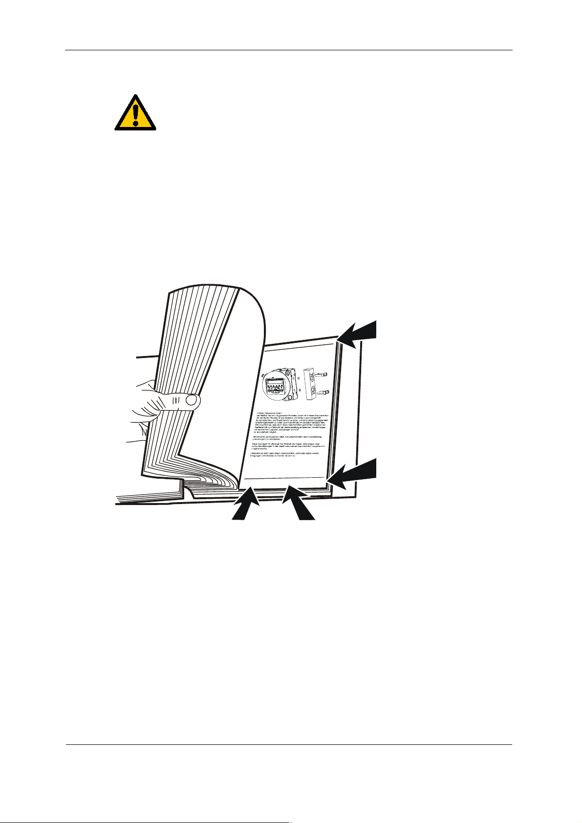
Using the Documentation
Note that the method described for locating specific information does
not release you from your responsibility of carefully reading these
instructions prior to starting the unit up for the first time and at regular
intervals in the future.
What do I want to know?
I determine which topic I am looking for.
Where can I find the information I’m looking for?
The documentation has a table of contents at the beginning. There, I select
the chapter I'm looking for and the corresponding page number.
Chapter description
l
t
e
i
p
a
K
t
/
k
d
u
o
P
r
Page number
i
l
t
e
t
e
c
r
h
n
i
k
G
m
b
H
H
Y
D
C
A
F
B
2
a
1
4
e
a
d
3
6
W
5
de
e
200x-xx-xx
Seite x
Edition date
Documentation no.
Document language
with index/
file name
The documentation number with its index enables you to order another copy of the
operating and maintenance instructions.
The index is incremented every time the manual is revised or changed.
HYDAC FILTER SYSTEMS GMBH
BeWa MM-KKE-M-C-U 3239239b en-us 2011-10-10.doc 2011-09-27
en
Page 6/32
Page 7

MM-KKE-M-C-U Safety information and instructions
Safety information and instructions
These operating instructions contain the key instructions for properly and safely
operating the measuring microscope.
Obligations and liability
The basic prerequisite for the safe and proper handling and operation of the
measuring microscope is knowledge of the safety instructions and warnings.
When handling the measuring microscope, please observe in particular these
operating and maintenance instructions, in particular the rules and regulations on
accident prevention applicable for the place of operation.
The measuring microscope has been designed and constructed in accordance with
current state of the art technology and recognized safety regulations. Nevertheless,
hazards may be posed to the life and limb of the individual using the unit, or the
ROCS or other material assets may be damaged.
Only use the measuring microscope as follows:
Only for proper or designated use.
Only when in safe, perfect condition.
Immediately remedy any malfunctions that might impair safety.
Our General Terms and Conditions apply. Any and all warranty and liability claims
for personal injuries and damage to property shall be excluded in the event they are
attributable to one or more of the following causes.
HYDAC FILTER SYSTEMS GMBH
BeWa MM-KKE-M-C-U 3239239b en-us 2011-10-10.doc 2011-09-27
en
Page 7/32
Page 8
MM-KKE-M-C-U Safety information and instructions
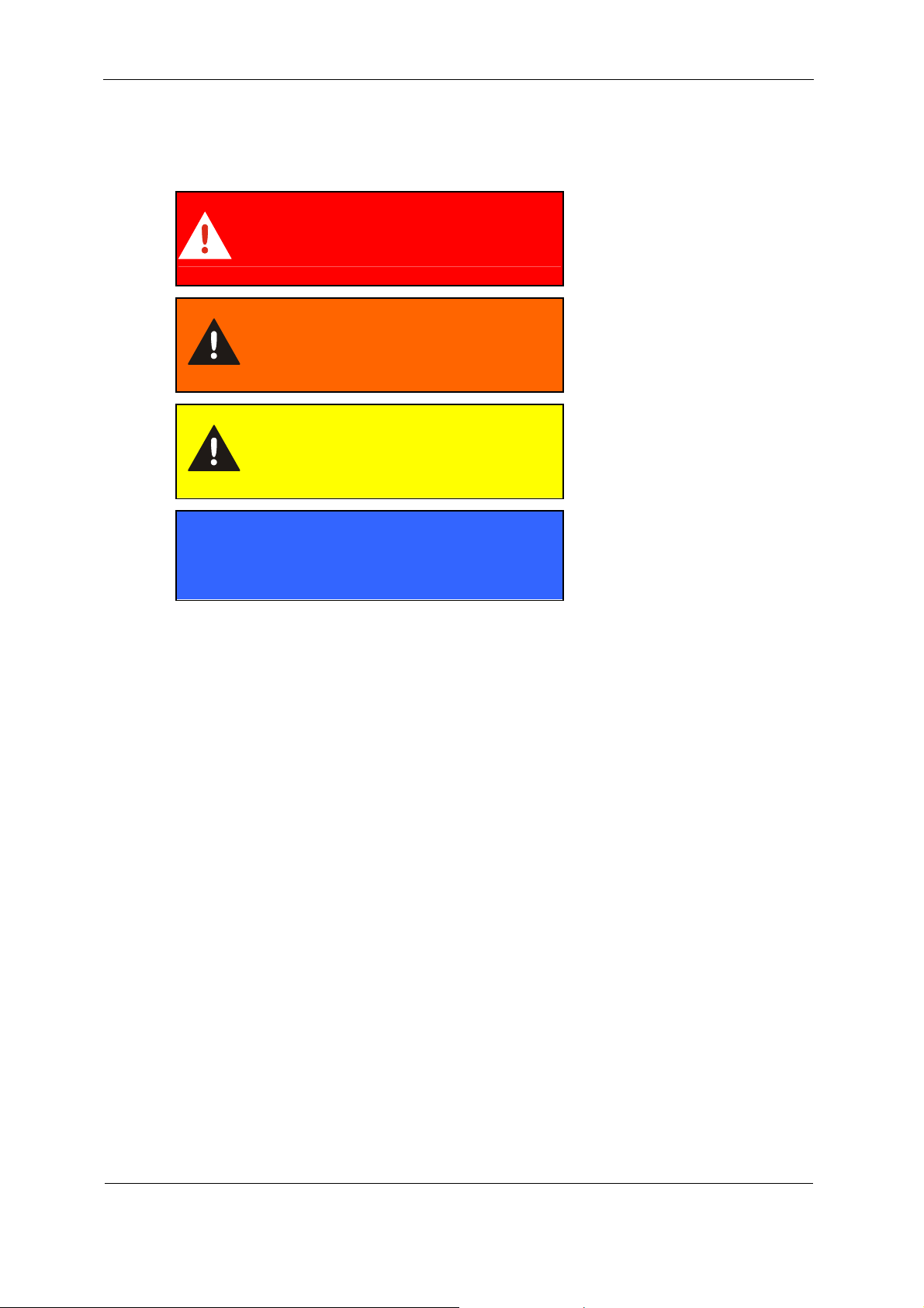
Explanation of Symbols and Warnings, etc.
The following designations and symbols are used in this manual to designate
hazards, etc.:
DANGER denotes situations
which can lead to death if
DANGER
WARNING
CAUTION
NOTICE
safety precautions are not
observed.
WARNING denotes situations
which can lead to death if
safety precautions are not
observed.
CAUTION denotes situations
which can lead to severe
injuries if safety precautions
are not observed.
NOTICE denotes situations
which can lead to property
damage if instructions are not
followed.
Proper/Designated Use
Use the measuring microscope for optical evaluation of filter membranes and for the
enlargement / visualization of particles etc.
Analyzing the type, size and quantity of contamination enables quality standards to
be verified and documented, and the requisite optimization measures to be
implemented.
Improper Use
Never look into the sun /sunlight using the microscope. This may damage your
eyesight.
HYDAC FILTER SYSTEMS GMBH
BeWa MM-KKE-M-C-U 3239239b en-us 2011-10-10.doc 2011-09-27
en
Page 8/32
Page 9
MM-KKE-M-C-U Transporting the microscope
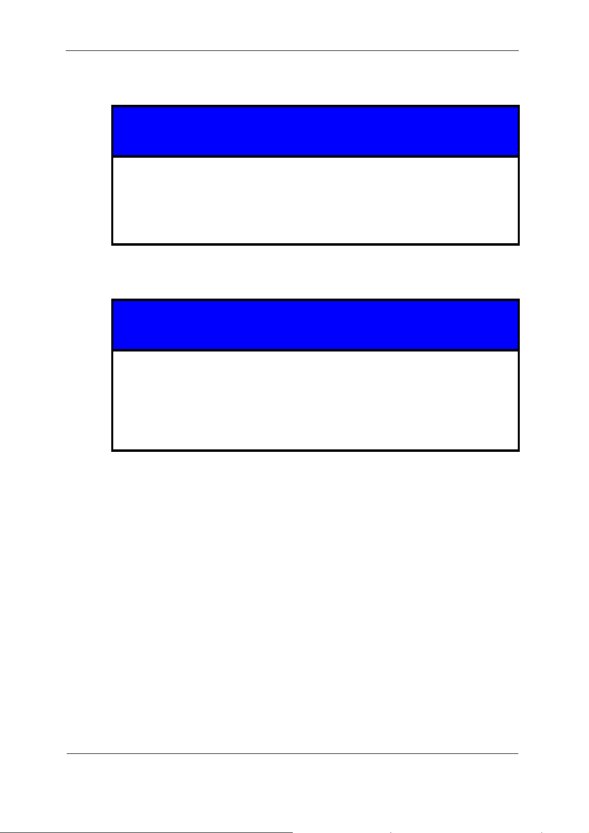
Transporting the microscope
NOTICE
Transporting the microscope without a transport container
The measuring microscope will be damaged.
► Transport the measuring microscope only in a closed transport container;
carry it in vertical position or by the handle.
Storing the microscope
NOTICE
Storing the microscope without a transport container
The measuring microscope will be damaged.
► Store the microscope in a clean and dry location in its closed transport case
and in a horizontal or vertical position. The microscope must not be exposed
to any shaking or vibration.
HYDAC FILTER SYSTEMS GMBH
BeWa MM-KKE-M-C-U 3239239b en-us 2011-10-10.doc 2011-09-27
en
Page 9/32
Page 10
MM-KKE-M-C-U Checking the Scope of Delivery
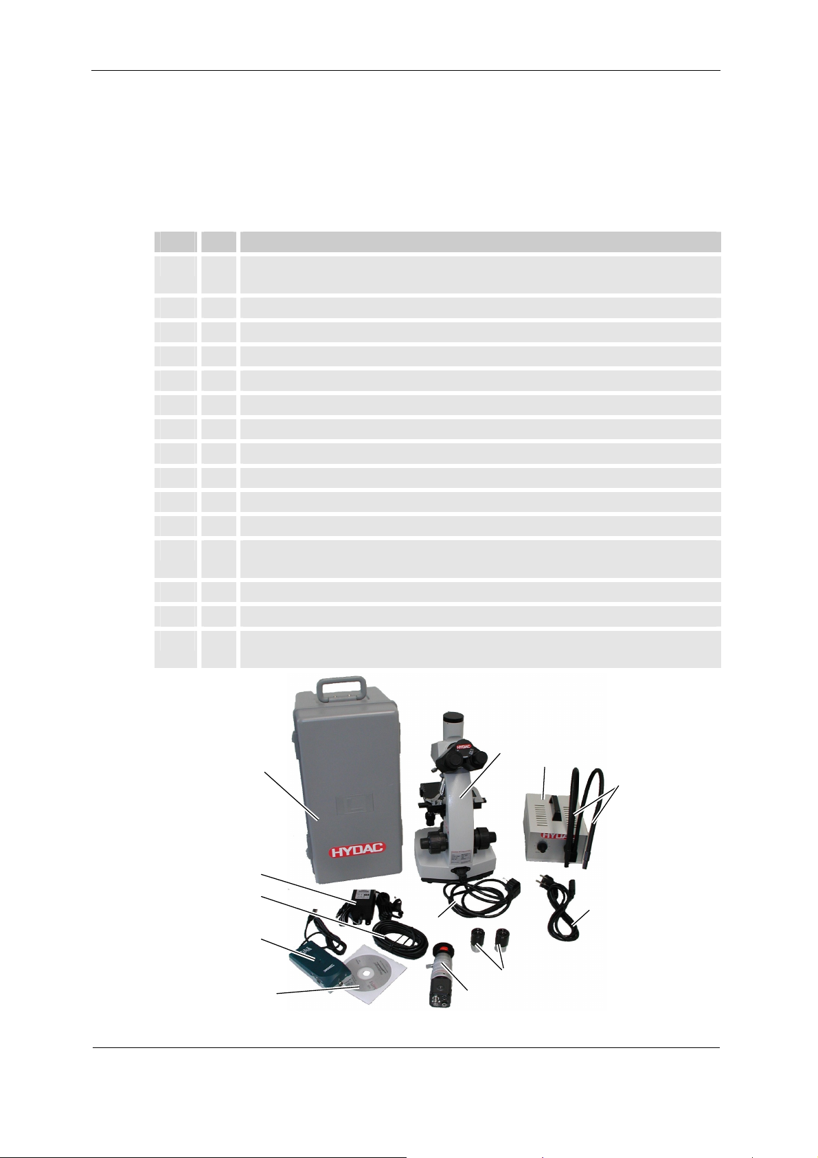
Checking the Scope of Delivery
The measuring microscope comes packed and partially factory-assembled. Before
commissioning, check the contents of the package to make sure it has not been
damaged during transport and that it is complete.
The following items are supplied:
Item Qty Description
1 1 Microscope stand with trinocular optical head, specimen stage,
objective lens turret and illuminator
2 2 Eyepiece
3 1 Objective lens 4:1 (already mounted on the objective lens turret)
4 1 Objective lens 10:1 (already mounted on the objective lens turret)
5 1 Objective lens 20:1 (already mounted on the objective lens turret)
6 2 Connection cable, L=1.5 m
7 1 Camera with micrometer eyepiece
8 1 Power supply for camera
9 1 S-VHS connection cable, L = 5 m
10 1 Cold light illuminator, 100 W
11 1 Fiber optic gooseneck, dual-arm
12 1 WinTV USB (external TV card) including
USB connection cable, L=1.8 m
13 1 CD-ROM containing the software for on-screen image viewing
14 1 Transport case
- 1 Replacement bulb, replacement fuse, ground glass plate (transparent /
blue-tinted)
1
14
8
10
11
9
12
13
6
2
7
6
HYDAC FILTER SYSTEMS GMBH
BeWa MM-KKE-M-C-U 3239239b en-us 2011-10-10.doc 2011-09-27
en
Page 10/32
Page 11

MM-KKE-M-C-U Microscope features
Microscope features
The microscope system consists of a trinocular microscope which is used with an
external cold light illuminator in incident light mode to examine the filter membranes
of oil samples. The microscope enables you to examine filter membranes with a
selectable magnification of 40x, 100x and 200x via a stereo microscope.
You can also examine filter membranes using the image processing system. The
image processing system consists of a CCD color camera and an external video/TV
tuner which is connected to your PC via the USB (Universal Serial Bus ) port.
The measurement scale integrated into the camera eyepiece enables the size of the
particles being examined to be precision-determined. The conversion table in mm
per graduation mark on the objective lens can be found on page 23.
The images recorded via the PC can be postprocessed as b
in MS-Word documents, for example.
System requirements
The following system requirements must be fulfilled for the installation:
Operating system: Windows 98, ME, 2000, XP, VISTA or 7
Hardware: Pentium 800 MHz
Free USB port 2.0
CD-ROM drive
itmaps and embedded
HYDAC FILTER SYSTEMS GMBH
BeWa MM-KKE-M-C-U 3239239b en-us 2011-10-10.doc 2011-09-27
en
Page 11/32
Page 12

MM-KKE-M-C-U Components on the microscope
Components on the microscope
Item Description
1 Camera with micrometer eyepiece
2 Switch-over between binocular / camera eyepiece
3 Power connection
4 Power switch for internal lighting
5 Illumination intensity adjustment dial for internal lighting
6
Adjustment lever for limiting the height setting of the x/y mechanical
stage
HYDAC FILTER SYSTEMS GMBH
BeWa MM-KKE-M-C-U 3239239b en-us 2011-10-10.doc 2011-09-27
en
Page 12/32
Page 13

MM-KKE-M-C-U Components on the microscope
Item Description Description
a) Eyepieces The eyepieces project the intermediate image on
the viewer's retina. Consequently it is the interface
between the microscope and the user.
b) Tube In this case the trinocular tube contains special
prisms which split the image produced by the
objective lens and supply the intermediate image to
both eyepieces.
In order to use the camera eyepiece the tube slider
has to be pulled out.
c) Dovetail ring Enables components to be quickly changed, in
addition to providing for a swivel range of 360°.
d) Stand Carries all components. Main components: arm and
base.
e) Objective lens turret
and objective lenses
The turret contains specially sized holes with an
internal thread for mounting the objective lenses. In
so doing it enables the objective lenses to be
"swiveled" into place.
f) Specimen stage
including x/y
HYDAC FILTER SYSTEMS GMBH
BeWa MM-KKE-M-C-U 3239239b en-us 2011-10-10.doc 2011-09-27
The specimen stage generally consists of a square
shaped plate featuring a hole or slit in the center
en
Page 13/32
Page 14

MM-KKE-M-C-U Components on the microscope
Item Description Description
mechanical stage through which the light from the light source can
shine for the purpose of illuminating the specimen.
The specimen slides are therefore guided precisely
using the x/y mechanical stage adjustment knob.
g) X/y mechanical
stage
Like the height adjustment of the specimen stage,
the x/y mechanical stage is equipped with a
precision mechanism, enabling the specimens to be
micrometer-precision-guided under the objective
lens even at large magnifications by virtue of the x/y
mechanical stage adjustment knob. The microscope
has a specimen clamp. The specimen slides are
clamped beneath it.
h) X/y mechanical
stage adjustment
knob
The two adjustment knobs enable the microscope to
be operated using one hand, with the lower knob
being used for horizontal adjustment and the upper
knob for vertical adjustment.
i) Condenser In addition to the eyepieces, prisms and objective
lenses it is the fourth optical component of the
microscope and important for illuminating the
specimen. The specimen could not be properly
illuminated without it.
The condenser is located underneath the specimen
stage and consists of a lens system and an iris stop,
or aperture diaphragm. The condenser serves to
optimally collect the microscope light for the
respective objective lens. When the aperture is
opened, resolution increases while contrast
decreases. The opposite effect is created when it is
closed, i.e. resolution decreases while contrast
increases. Consequently, the purpose of the
condenser is to enable an optimal compromise
between resolution and contrast to be set for the
respective specimen. The aperture diaphragm has
to be readjusted every time the objective lens is
changed.
j) Condenser
adjustment knob
k) Coarse and fine
adjustment knob
Enables the condenser to be precision-raised and
lowered.
This knob enables the specimen stage to be heightadjusted with micrometer precision. The coarse and
fine adjustment is featured as a separate series of
knobs, with the fine adjustment knob being smaller
than and mounted onto the larger coarse adjustment
knob. They enable the specimen to be precisionfocused.
l) Internal lighting
source
A light source is needed to illuminate a specimen,
the light being projected through the condenser into
the specimen and then projected by this in turn into
the objective lens and the eyepiece. The
HYDAC FILTER SYSTEMS GMBH
BeWa MM-KKE-M-C-U 3239239b en-us 2011-10-10.doc 2011-09-27
en
Page 14/32
Page 15

MM-KKE-M-C-U Components on the microscope
Item Description Description
microscope possesses a special artificial light
source featuring a collector and field diaphragm,
making using the microscope easier and the user
more independent.
m) Aperture diaphragm
Used for centering the field diaphragm image.
adjuster
n) Ground glass plate Serves to diffuse light and is slid into a specially
constructed slit between the lamp and collector. It
enables light to be distributed evenly without colored
fringes.
HYDAC FILTER SYSTEMS GMBH
BeWa MM-KKE-M-C-U 3239239b en-us 2011-10-10.doc 2011-09-27
en
Page 15/32
Page 16

MM-KKE-M-C-U Installing the microscope
Installing the microscope
Proceed as follows to install the microscope:
1. Place the microscope stand on a stable
surface.
2. Remove the covers.
Push both of the eyepieces into the
binocular tube.
3. Insert the connection cable into the
microscope.
You require this power supply only for
the internal, lower lighting.
The microscope has a condenser and a
source of lighting for transmitted light
mode.
This light source is normally not suitable
for examining filter membranes.
4. The assembly of your microscope is
complete.
HYDAC FILTER SYSTEMS GMBH
BeWa MM-KKE-M-C-U 3239239b en-us 2011-10-10.doc 2011-09-27
en
Page 16/32
Page 17

MM-KKE-M-C-U Assembling the illuminator (cold light source)
Assembling the illuminator (cold light source)
Proceed as follows to install the illuminator:
1. The illuminator consists of a base unit
with a 12 V 100 W halogen lamp and a
fiber optic gooseneck.
Please check the connection voltage
according to the technical data on the
type label.
2. The front of the base unit contains a
mount for the fiber optic gooseneck.
First loosen the setscrew on the mount
so that the mounting pin can be slid into
the mounting hole.
Ensure that the flexible fiber optic arms
face vertically upwards. Flatten the top
of the mounting pin to secure it against
twisting.
Screw the setscrew in and tighten it
gently.
3. Plug the connector cable into the
illuminator.
Fehler! Es ist nicht möglich,
durch die Bearbeitung von
Feldfunktionen Objekte zu
erstellen.
Fehler! Es ist nicht möglich,
durch die Bearbeitung von
Feldfunktionen Objekte zu
erstellen.
HYDAC FILTER SYSTEMS GMBH
BeWa MM-KKE-M-C-U 3239239b en-us 2011-10-10.doc 2011-09-27
en
Page 17/32
Page 18

MM-KKE-M-C-U Assembling the illuminator (cold light source)
4. Switch on the illuminator using the
rotary button [a] at the front and regulate
the brightness.
The illuminator has a fan to cool the
lamp. This fan makes a small amount of
noise when in operation.
5. The illuminator is now ready for use.
Fehler! Es ist nicht möglich,
durch die Bearbeitung von
Feldfunktionen Objekte zu
erstellen.
HYDAC FILTER SYSTEMS GMBH
BeWa MM-KKE-M-C-U 3239239b en-us 2011-10-10.doc 2011-09-27
en
Page 18/32
Page 19

MM-KKE-M-C-U Installing and setting the camera
Installing and setting the camera
Check the camera settings as shown in the following illustration:
Factory settings — Camera configuration settings
Proceed as follows to install the camera:
1. Undo the knurled pin [2]
counterclockwise until the protective
cap [1] can easily be removed.
2. Place the camera [3] with the
measuring eyepiece [4] onto the
trinocular and tighten the knurled pin [2]
lightly by hand.
3. The microscope can be operated using
either the stereo eyepiece or the
camera eyepiece.
Switch between the two eyepieces by
inserting or pulling out the knurled pin
on the right of the trinocular optical
head.
Fehler! Es ist nicht möglich,
durch die Bearbeitung von
Feldfunktionen Objekte zu
erstellen.
Fehler! Es ist nicht möglich,
durch die Bearbeitung von
Feldfunktionen Objekte zu
erstellen.
When operating the microscope using
the camera eyepiece, the knurled pin of
the trinocular optical head has to be
pulled out.
4. Connect the external adaptor to supply
power to the camera. To do this, use
only the adaptor included in the
measuring microscope scope of
Fehler! Es ist nicht möglich,
durch die Bearbeitung von
Feldfunktionen Objekte zu
erstellen.
delivery.
Plug the power supply into the POWER
IN jack of the camera using the right
plug, and then plug the power plug into
the wall outlet. The camera’s POWER
indicator light should now light up and
stay lit..
HYDAC FILTER SYSTEMS GMBH
BeWa MM-KKE-M-C-U 3239239b en-us 2011-10-10.doc 2011-09-27
en
Page 19/32
Page 20

MM-KKE-M-C-U Installing and setting the camera
5. Connect the camera with the S-VHS
connection cable with the "Y/C OUT"
camera jack and …
6. ..... and the C-Video IN jack of the TV
tuner.
7. Connect the external TV tuner to a nonused USB 2.0 port of your PC using the
USB cable.
8. The camera is now connected to your
PC and ready for operation.
Installing the image processing software
To install the image processing software, read the installation instructions which
come with the microscope or the camera.
Fehler! Es ist nicht möglich,
durch die Bearbeitung von
Feldfunktionen Objekte zu
erstellen.
Fehler! Es ist nicht möglich,
durch die Bearbeitung von
Feldfunktionen Objekte zu
erstellen.
HYDAC FILTER SYSTEMS GMBH
BeWa MM-KKE-M-C-U 3239239b en-us 2011-10-10.doc 2011-09-27
en
Page 20/32
Page 21

MM-KKE-M-C-U Operating the microscope
Operating the microscope
Switch on the cold light illuminator and set the illumination intensity desired using
the dial. Position the fiber optic arms so that no shadows are cast on the specimen
being examined.
Fix the membrane to be examined along with the membrane support on the x/y
mechanical stage. To do this, swivel the curved x/y mechanical stage arm outwards
and then clamp the specimen slide in place.
Adjust the interpupillary spacing of the two eyepiece tubes as required for viewing.
To do this, slide the two tubes into one another or pull them apart as needed.
The microscope can be operated using either the stereo eyepiece or the camera
eyepiece. Lenses can be selected by pushing in or pulling out the silver-colored
knurled pin on the right of the trinocular optical head. When operating the
microscope using the binocular tube for direct visual examination, the knurled pin
has to be inserted.
Rotate the turret to the objective lens with the lowest magnification and focus it on
the specimen. Focusing takes place using the coarse and fine adjustment, which is
operated using the wheels mounted on the right and left-hand sides of the stand.
Coarse adjustment is done using the larger wheel. Fine adjustment is carried out
using the smaller wheel located on top of the larger wheel for coarse adjustment.
Dioptric compensation on the eyepieces is carried out to compensate for the
difference in vision between the user’s eyes. This has to be individually adjusted for
everyone using the microscope.
The x/y mechanical stage provides for adjustment in an X and Y direction.
HYDAC FILTER SYSTEMS GMBH
BeWa MM-KKE-M-C-U 3239239b en-us 2011-10-10.doc 2011-09-27
en
Page 21/32
Page 22

MM-KKE-M-C-U Performing a measurement
Performing a measurement
Three different objective lenses (magnification: 4:1, 10:1 and 20:1) can be selected.
The eyepieces on the microscope possess a magnification of 10x. Both scale ratios
are multiplied so that the total magnifications 40x, 100x and 200x result.
This results in the following scale ratios:
Objective lens Total magnification 1 scale graduation line
corresponds to:
4 : 1 40x ~ 25 µm
10 : 1 100x ~ 10 µm
20 : 1 200x ~ 5 µm
Place the filter membrane to be examined along with the membrane support on the
specimen stage. If present, remove the see-through protective cover from the
membrane support. Pull the spring-loaded x/y mechanical stage clip outwards using
your finger and slip the membrane support into the holder. The membrane support is
fixed in place as soon as you let go of the stage clip.
Examining the specimen under the microscope is facilitated by the illuminator.
Rotate the turret to the objective lens with the lowest magnification (4:1) and focus it
on the specimen. Focusing is carried out using the coarse and fine adjustment knob.
The micrometer eyepiece of the camera can be used to gauge the size of the
specimen under the microscope. This is done by taking a reading of the particle size
via the micrometer scale and multiplying the number of graduated scale lines by the
scale associated with the respective magnification. The scale can also be found by
referring to the type plate affixed to the back of the stand or on the camera.
HYDAC FILTER SYSTEMS GMBH
BeWa MM-KKE-M-C-U 3239239b en-us 2011-10-10.doc 2011-09-27
en
Page 22/32
Page 23

MM-KKE-M-C-U Evaluating a filter membrane / sample
Evaluating a filter membrane / sample
Particle size ~ 1.2 scale graduation lines
Particle size ~ 2 scale graduation lines
Conversion of the measurement results: (example)
Objective lens
used
1 scale
graduation line
corresponds to:
X Particle size
measured
(in scale graduation
= Accords with
lines)
4 : 1 25 µm X ~ 1.2 = 30 µm
4 : 1 25 µm X ~ 2 = 50 µm
10 : 1 10 µm X ~ 1.2 = 12 µm
10 : 1 10 µm X ~ 2 = 20 µm
20 : 1 5 µm X ~ 1.2 = 6 µm
20 : 1 5 µm X ~ 2 = 10 µm
particle size
HYDAC FILTER SYSTEMS GMBH
BeWa MM-KKE-M-C-U 3239239b en-us 2011-10-10.doc 2011-09-27
en
Page 23/32
Page 24

MM-KKE-M-C-U Performing Maintenance
Performing Maintenance
Prior to all maintenance and cleaning work, disconnect the power plug to the
microscope / illuminator.
DANGER
Electric shock
Danger of fatal injury
► Disconnect the power plug on the unit before
performing any maintenance work.
► Any work involving the electrical equipment may
only be done by a properly trained, certified
electrician.
Cleaning / maintaining the microscope
Clean the microscope surface regularly using a soft cloth or brush. Use only a mild
soap solution for stubborn contamination.
The optical components are to be cleaned using a clean, dry lint-free linen cloth or
lens cleaning paper. Remove any stubborn coating with extreme care using a cloth
soaked in alcohol.
HYDAC FILTER SYSTEMS GMBH
BeWa MM-KKE-M-C-U 3239239b en-us 2011-10-10.doc 2011-09-27
en
Page 24/32
Page 25

MM-KKE-M-C-U Performing Maintenance
Replacing the bulb on the microscope
Proceed as follows to change the bulb on the microscope:
1. Pull power plug.
2. Remove the eyepieces from the microscope
tubes.
3. Loosen the knurled pin and remove the
camera unit.
4. Let the lamp in the microscope cool down.
Slowly turn the microscope on its side so that
the underside of the microscope is easily
accessible.
[A] Open the knurled pin to the lamp flap.
[B] Knurled pin for adjusting the lamp..
[C] Temperature fuse plug for lamp.
5. Undo the knurled pin [A] by turning it in a
counterclockwise direction and open the lamp
flap.
HYDAC FILTER SYSTEMS GMBH
BeWa MM-KKE-M-C-U 3239239b en-us 2011-10-10.doc 2011-09-27
en
Page 25/32
Page 26

MM-KKE-M-C-U Performing Maintenance
6. Remove the cooled, defective bulb by pulling
it.
7.
Touch the new bulb only in a cloth
and not with your bare fingers. Fingerprints
burn in during operation.
Plug the lamp into the base.
Replacement bulb: Type: 10W 6V OSRAM
no. 644410 S
8. The bulb replacement is complete..
HYDAC FILTER SYSTEMS GMBH
BeWa MM-KKE-M-C-U 3239239b en-us 2011-10-10.doc 2011-09-27
en
Page 26/32
Page 27

MM-KKE-M-C-U Performing Maintenance
Replacing the illuminator bulb
Proceed as follows to change the bulb on the illuminator:
1. Switch off the illuminator.
Pull power plug.
Allow the unit to cool down.
2. Remove the 4 Phillips head screws on the two
side panels of the housing and lift up the upper
part of the housing by the handle.
3. Disconnect the plug from the bulb.
Push the bulb upwards out of the fitting.
Slide the new bulb into the light fitting from
above.
(Replacement bulb Type: 12V 100W Philips
No. 6834 )
Connect the plug to the lamp again.
4. Mount the housing lid and screw in the 4
Phillips head screws again.
Plug in the power plug and switch on the
illuminator.
5. The bulb replacement is complete..
HYDAC FILTER SYSTEMS GMBH
BeWa MM-KKE-M-C-U 3239239b en-us 2011-10-10.doc 2011-09-27
en
Page 27/32
Page 28

MM-KKE-M-C-U Disposing of your microscope
Disposing of your microscope
Dispose of the packaging material as appropriate for your area.
When decommissioning and/or disposing, observe all local guidelines and
regulations pertaining to occupational safety and environmental protection. This
applies in particular to the oil in the unit, components covered with oil and
electronical components.
After disassembling the unit and separating the various materials, reuse them or
dispose of them properly in accordance with local regulations.
HYDAC FILTER SYSTEMS GMBH
BeWa MM-KKE-M-C-U 3239239b en-us 2011-10-10.doc 2011-09-27
en
Page 28/32
Page 29

MM-KKE-M-C-U Model Code
Model Code
MM - KKE - M - C - U
Basic type
MM = Measuring microscope
Lens system
KKE = Trinocular
Supply voltage
O = 240 V AC / 50 Hz / 1 Phase (Australia)
M = 230 V AC / 50 Hz / 1 Phase (Europe)
P = 100 V AC / 50 Hz / 1 Phase (Japan)
Accessories
C = Cold light lighting
Z = Without
Supply voltage
U = CCD camera with USB port
HYDAC FILTER SYSTEMS GMBH
BeWa MM-KKE-M-C-U 3239239b en-us 2011-10-10.doc 2011-09-27
en
Page 29/32
Page 30

MM-KKE-M-C-U Technical Data
Technical Data
Measuring microscope
Huygens eyepiece 10 x M
Achromatic lenses 4x 10x 20x
Magnifications 40x 100x 200x
Tube length 160 mm
Total height 330 mm
Paint colour light grey
PC interface USB port 2.0
Ambient temperature range 0° … +45° C / 32° … 113° F
Storage temperature range -40° … +80 C / -40° … 176° F
Relative humidity max. 90%, non-condensing
Weight ~ 13 kg
Electrical data
Supply voltage 24 V DC, ± 20%, residual ripple ≤ 10%
Power consumption / electricity 100 W max. / 4 A max.
IP class IP 50 (open, in operation)
IP 67 (closed)
Protection class III (safety extra-low voltage)
HYDAC FILTER SYSTEMS GMBH
BeWa MM-KKE-M-C-U 3239239b en-us 2011-10-10.doc 2011-09-27
en
Page 30/32
Page 31

Page 32

HYDAC FILTER SYSTEMS GMBH
Industriegebiet Postfach 1251
66280 Sulzbach/Saar 66273 Sulzbach/Saar
Germany Germany
Phone: +49 (0) 6897 509 01 Central
Fax: +49 (0) 6897 509 846 (Technical Department)
Fax: +49 (0) 6897 509 577 (Sales Department)
Internet: www.hydac.com
Email: filtersystems@hydac.com
 Loading...