

Page 1

Operation and Installation Guide
Documentation no.: 4366964
MCS /-C062
Metallic
Contamination Sensor
English (translation of original instructions)
Valid from hardware index B and
firmware version C09.30 up
Page 2

Imprint
HYDAC FILTER SYSTEMS GMBH
Industriegebiet
66280 Sulzbach / Saar
Germany
Telephone:
+49 6897 509 01
Fax:
+49 6897 509 9046
E-mail:
filtersystems@hydac.com
Homepage:
www.hydac.com
Court of Registration:
Saarbrücken, HRB 17216
Executive director:
Mathias Dieter,
Mr. Günter Harge
c/o HYDAC International GmbH, Industriegebiet, 66280 Sulzbach / Saar
Telephone:
+49 6897 509 1511
Fax:
+49 6897 509 1394
E-mail:
guenter.harge@hydac.com
Imprint
Manufacturer / publisher and responsible for the content:
Dipl.Kfm. Wolfgang Haering
Documentation Representative
© HYDAC FILTER SYSTEMS GMBH
All rights reserved. No part of this work may be reproduced in any form (print,
photocopy or by other means) or processed, duplicated or distributed using
electronic systems without the written consent of the publisher.
These documents have been created and inspected with the greatest care.
However, errors cannot be ruled out completely.
MCS /-C062
BeWa MCS1000-C062 4366964 C0930x en-us 2018-06-
25.docx
en(us)
Page 2 / 76
2018-06-25
Page 3

Content
Content
Imprint ............................................................................................................ 2
Documentation Representative ................................................................... 2
Content .......................................................................................................... 3
Preface ........................................................................................................... 7
Safety Information ........................................................................................ 9
Technical Support ........................................................................................ 7
Modifications to the Product ........................................................................ 7
Warranty ...................................................................................................... 7
Using the documentation ............................................................................. 8
Warning signs used ..................................................................................... 9
Others used symbols ................................................................................... 9
Signal words and their meaning in the general safety information ............. 10
Structure of the safety information and instructions ................................... 10
Observe regulatory information ................................................................. 11
Proper/designated use............................................................................... 11
Improper Use or Use Deviating from Intended Use ................................... 12
Qualifications of personnel / target group .................................................. 13
Transporting the sensor ............................................................................. 14
Storing the sensor ...................................................................................... 14
Decoding the model code label ................................................................. 15
Checking the scope of delivery ................................................................. 16
Scope of delivery for MCS 13xx ................................................................ 16
Scope of delivery for MCS 14xx ................................................................ 17
Scope of delivery for MCS 15xx ................................................................ 18
Sensor features ........................................................................................... 19
Functional principle .................................................................................... 19
Sensor dimensions ..................................................................................... 20
Dimensions MCS 13xx .............................................................................. 20
Dimensions for MCS 13xx with Ethernet module ....................................... 21
Dimensions MCS 13xx with flange adapter set (optional
accessories) .............................................................................................. 22
Dimensions MCS 14xx .............................................................................. 23
Dimensions for MCS 14xx with Ethernet ................................................... 24
Dimensions MCS 14xx with flange adapter set (optional
accessories) .............................................................................................. 25
Dimensions MCS 15xx .............................................................................. 26
Dimensions for MCS 15xx with Ethernet ................................................... 27
MCS /-C062
BeWa MCS1000-C062 4366964 C0930x en-us 2018-06-
25.docx
en(us)
Page 3 / 76
2018-06-25
Page 4

Content
Dimensions MCS 15xx with flange adapter set (optional
accessories) .............................................................................................. 28
Mechanical installation/assembly ............................................................. 29
Connecting MCS13xx / 14xx via flange adapter set .................................. 30
Fastening sensor to underside .................................................................. 31
Fastening MCS 13xx / MCS 14xx .............................................................. 32
Fastening MCS 15xx ................................................................................. 32
Fastening MCS 15xx using angle fastening set ......................................... 33
Connecting MCS 15xx using pipe adapter set ........................................... 33
Connecting MCS 15xx using flange adapter plate (accessory) ................. 34
MCS 15xx via SAE 4" per ISO 6162-1 (4xM16) ......................................... 35
Hydraulic installation of sensor ................................................................. 36
Diagram - flow rate, differential pressure p∆ and viscosity ν .................. 36
Electrical connection of sensor ................................................................. 38
Plug pin assignment .................................................................................. 38
Connection cable - Assignment / Color coding .......................................... 39
Using the switching outputs ...................................................................... 40
Switching output - FE.NFE ........................................................................ 40
Switching output - ALL.RDY (factory setting) ............................................. 40
Switching output - ALARM ......................................................................... 40
Switching logic "active low" ........................................................................ 41
Example: Operation - 1 particle detected ............................................... 41
Example: Operation - no particle detected ............................................. 41
Example: Operation - several particles detected .................................... 42
Switching logic "active high" ...................................................................... 43
Example: Operation - 1 particle detected ............................................... 43
Example: Operation - no particle detected ............................................. 43
Example: Operation - several particles detected .................................... 44
Switching output "Device Ready" .............................................................. 44
Parameterizing sensor/reading measured values .................................... 45
Connecting MCS 1000 to SMU 1200 ......................................................... 45
Connecting MCS to CSI-D-5 (Condition Sensor Interface) ........................ 46
Connecting MCS to HMG 3000 ................................................................. 47
Evaluating measurement results ............................................................... 48
Menu structure ............................................................................................ 49
Overview - Power Up Menu ....................................................................... 49
Overview - Measuring Menu ...................................................................... 50
PowerUp Menu ............................................................................................ 51
MODE - select operating mode ................................................................. 51
MCS /-C062
BeWa MCS1000-C062 4366964 C0930x en-us 2018-06-
25.docx
en(us)
Page 4 / 76
2018-06-25
Page 5

Content
S.TIME - Set storing interval ...................................................................... 51
SEL.COM - Set protocol ............................................................................ 51
ADRESS – Set bus address ...................................................................... 51
DFAULT - Reset to factory setting ............................................................. 51
CANCEL - cancel without saving ............................................................... 51
SAVE - save changes ................................................................................ 51
Measuring menu ......................................................................................... 52
DSPLAY - Show measured variable .......................................................... 52
SWT.OUT – Set the switching output ........................................................ 53
SWT.LOG - Set logic at the switching output ............................................. 54
SWT.PLS - Set pulse length at the switching output ................................. 54
SWT.TST – Set test pulse at the switching output ..................................... 54
ALARM – Setting limit values .................................................................... 55
CANCEL - cancel without saving ............................................................... 55
SAVE - Save changes ............................................................................... 55
Error analysis / remedy .............................................................................. 56
Error status - "active high" and "active low" ............................................... 58
Error status 1 "active low"....................................................................... 58
Error status 1 "active high" ..................................................................... 59
Error status 2 "active low"....................................................................... 60
Error status 2 "active high" ..................................................................... 61
Error status - "Device Ready" .................................................................... 61
Performing maintenance ............................................................................ 62
Decommissioning the sensor .................................................................... 62
Disposing of sensor/packaging material .................................................. 62
Spare Parts and Accessories .................................................................... 63
Channel default settings ............................................................................ 66
Calibrating the sensor ................................................................................ 66
Customer Service/ Service ......................................................................... 66
Technical Data............................................................................................. 67
Detection limits .......................................................................................... 68
Model Code ................................................................................................. 69
EC declaration of conformity ..................................................................... 69
Glossary ...................................................................................................... 70
Ferromagnetic (Fe) .................................................................................... 70
Non-ferromagnetic (nFe) ........................................................................... 70
Certification ................................................................................................ 70
Basics of GL certification ........................................................................ 71
MCS /-C062
BeWa MCS1000-C062 4366964 C0930x en-us 2018-06-
25.docx
en(us)
Page 5 / 76
2018-06-25
Page 6

Content
Germanischer Lloyd Industrial Services GmbH, renewable
energies ..................................................................................................... 71
Index ............................................................................................................ 72
MCS /-C062
BeWa MCS1000-C062 4366964 C0930x en-us 2018-06-
25.docx
en(us)
Page 6 / 76
2018-06-25
Page 7

Preface
Fax:
+49 6897 509 9046
E-mail:
filtersystems@hydac.com
Preface
This operating manual was made to the best of our knowledge. Nevertheless
and despite the greatest care, it cannot be excluded that mistakes could have
crept in. Therefore please understand that in the absence of any provisions
to the contrary hereinafter our warranty and liability – for any legal reasons
whatsoever – are excluded in respect of the information in these operating
instructions. In particular, we shall not be liable for lost profit or other financial
loss. This exclusion of liability does not apply in cases of intent and gross
negligence. Moreover, it does not apply to defects which have been
deceitfully concealed or whose absence has been guaranteed, nor in cases
of culpable harm to life, physical injury and damage to health. If we
negligently breach any material contractual obligation, our liability shall be
limited to foreseeable damage. Claims due to Product Liability shall remain
unaffected.
Technical Support
Contact our technical sales department if you have any questions on our
product. When contacting us, please always include the model/type
designation, serial no. and part-no. of the product:
Modifications to the Product
We would like to point out that changes to the product (e.g., purchasing
options, etc.) may result in the information in the operating instructions no
longer being completely accurate or sufficient.
After modification or repair work that affects the safety of the product has
been carried out on components, the product may not be returned to
operation until it has been checked and released by a HYDAC technician.
Please notify us immediately of any modifications made to the product
whether by you or a third party.
Warranty
For the warranty provided by us, please refer to the terms of delivery of
HYDAC FILTER SYSTEMS GMBH.
You will find these under www.hydac.com -> Legal information.
MCS /-C062
BeWa MCS1000-C062 4366964 C0930x en-us 2018-06-
25.docx
en(us)
Page 7 / 76
2018-06-25
Page 8
Preface
Note that the method described for locating specific information
these instructions prior to starting the unit up for the first time and
de
H
Y
D
A
C
F
i
l
t
e
r
t
e
c
h
n
i
k
G
m
b
H
B
e
W
a
1
2
3
4
5
6
a
d
e
Seite x
P
r
o
d
u
k
t /
K
a
p
i
t
e
l
200x-xx-xx
Chapter description
Page number
Document language
Documentation no.
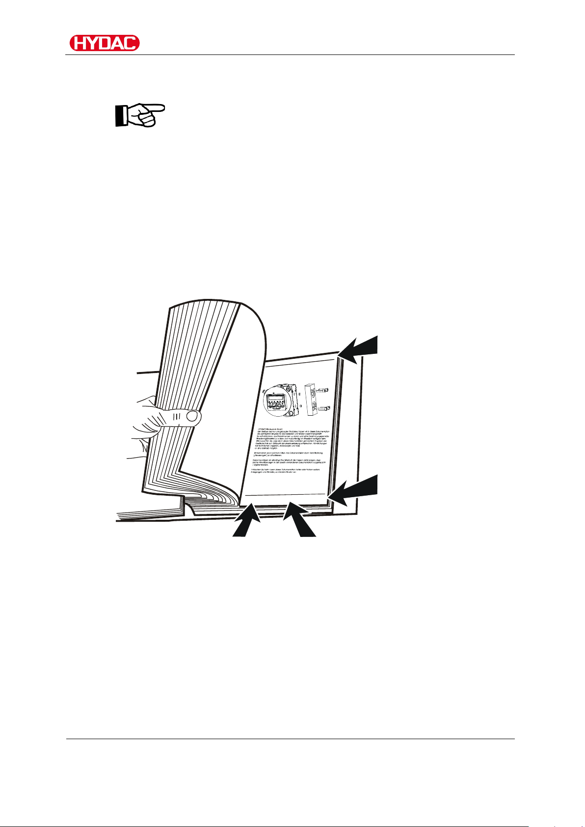
Using the documentation
does not release you from your responsibility of carefully reading
at regular intervals in the future.
What do I want to know?
I determine which topic I am looking for.
Where can I find the information I’m looking for?
The documentation has a table of contents at the beginning. There, I select
the chapter I'm looking for and the corresponding page number.
Edition date
with index/
file name
The documentation number with its index enables you to order another copy
of the operating and maintenance instructions. The index is incremented
every time the manual is revised or changed.
MCS /-C062
BeWa MCS1000-C062 4366964 C0930x en-us 2018-06-
25.docx
en(us)
Page 8 / 76
2018-06-25
Page 9
Safety Information
Safety Information
The device was built according to the statutory provisions valid at the time of
delivery and satisfies current safety requirements.
Any residual hazards are indicated by safety information and instructions and
are described in the operating instructions.
Observe all safety and warning instructions attached to the unit. They must
always be complete and legible.
Do not operate the unit unless all the safety devices are present.
Secure the hazardous areas which may arise between the unit and other
equipment.
Maintain the unit inspection intervals prescribed by law.
Document the results in an inspection certificate and keep it until the next
inspection.
Warning signs used
These signs are listed for all safety information and instructions in these
operating instructions which indicate particular hazards to persons, property
or the environment.
Others used symbols
The following symbols found you in this operation instructions.
Danger point warning
Dangerous electrical voltage warning
Tip for handling the product
Tools required
MCS /-C062
BeWa MCS1000-C062 4366964 C0930x en-us 2018-06-
25.docx
en(us)
Page 9 / 76
2018-06-25
Page 10
Safety Information
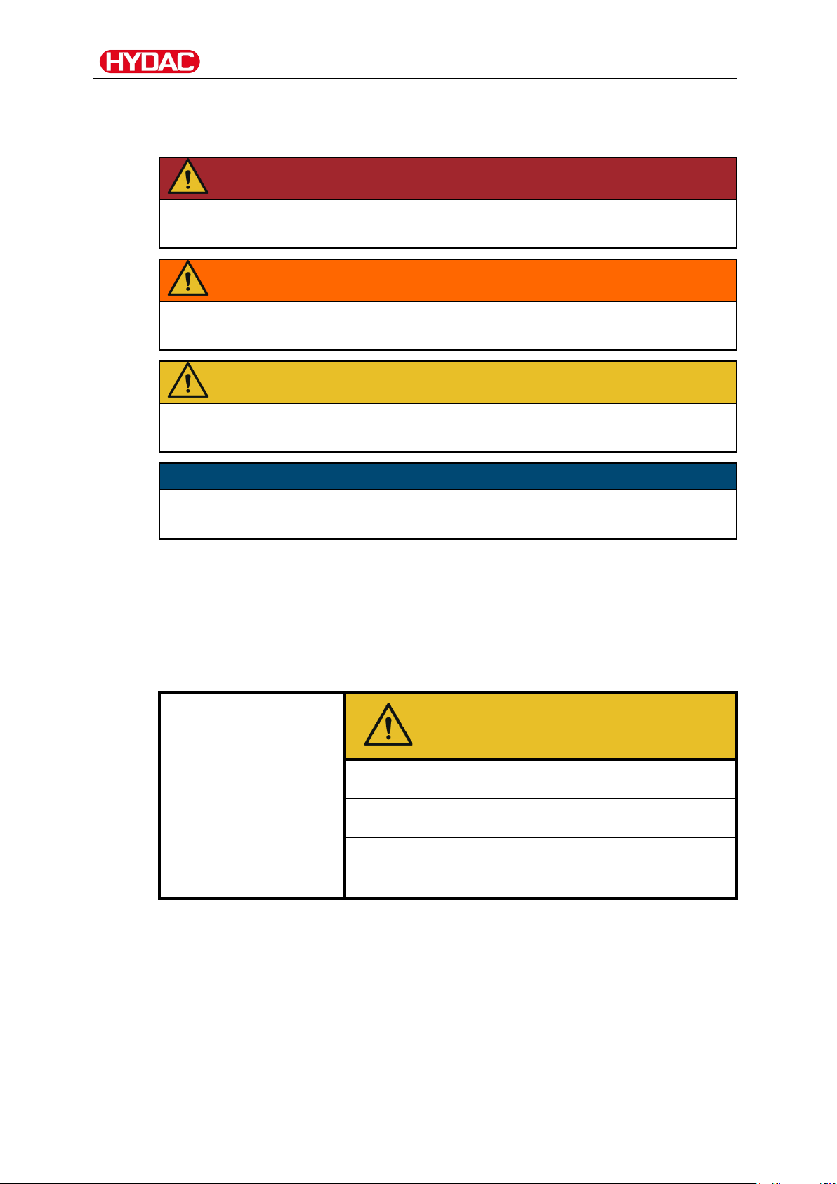
DANGER
DANGER – The signal word indicates a hazardous situation with a high level
of risk, which, if not avoided, will result lethal or serious injury.
WARNING
WARNING – The signal word indicates a hazardous situation with a medium
level of risk,
CAUTION
CAUTION – The signal word indicates a hazardous situation with a low level
of risk, which, if not avoided, can result in minor or moderate injury.
NOTICE
NOTICE – The signal word indicates a hazardous situation with a high level
of risk, which, if not avoided, will result in damage to property.
Signal words and their meaning in the general safety information
In these instructions you will find the following signal words:
which, if not avoided, can result lethal or serious injury.
Structure of the safety information and instructions
All warning instructions in this manual are highlighted with pictograms and
signal words. The pictogram and the signal word indicate the severity of the
danger.
Warning instructions listed before an activity are laid out as follows:
HAZARD SYMBOL
SIGNAL WORD
Type and source of danger
Consequence of the danger
► Measures to avert danger
MCS /-C062
BeWa MCS1000-C062 4366964 C0930x en-us 2018-06-
25.docx
en(us)
Page 10 / 76
2018-06-25
Page 11
Safety Information
Observe regulatory information
Observe the following regulatory information and guidelines:
• Legal and local regulations for accident prevention
• Legal and local regulations for environmental protection
• Country-specific regulations, organization-specific regulations
Proper/designated use
Only use the sensor for the application described in the following.
The MetallicContamination Sensor MCS is used for the constant monitoring
of particulate contamination in hydraulic and lubrication systems.
Proper or designated use of the product extends to the following:
• observing all instructions contained in the instruction manual.
• Only using with the permissible media.
• Operation within permissible technical conditions, such as operating
pressure, flow rate, media and ambient temperature.
The sensor is only to be used with the following media:
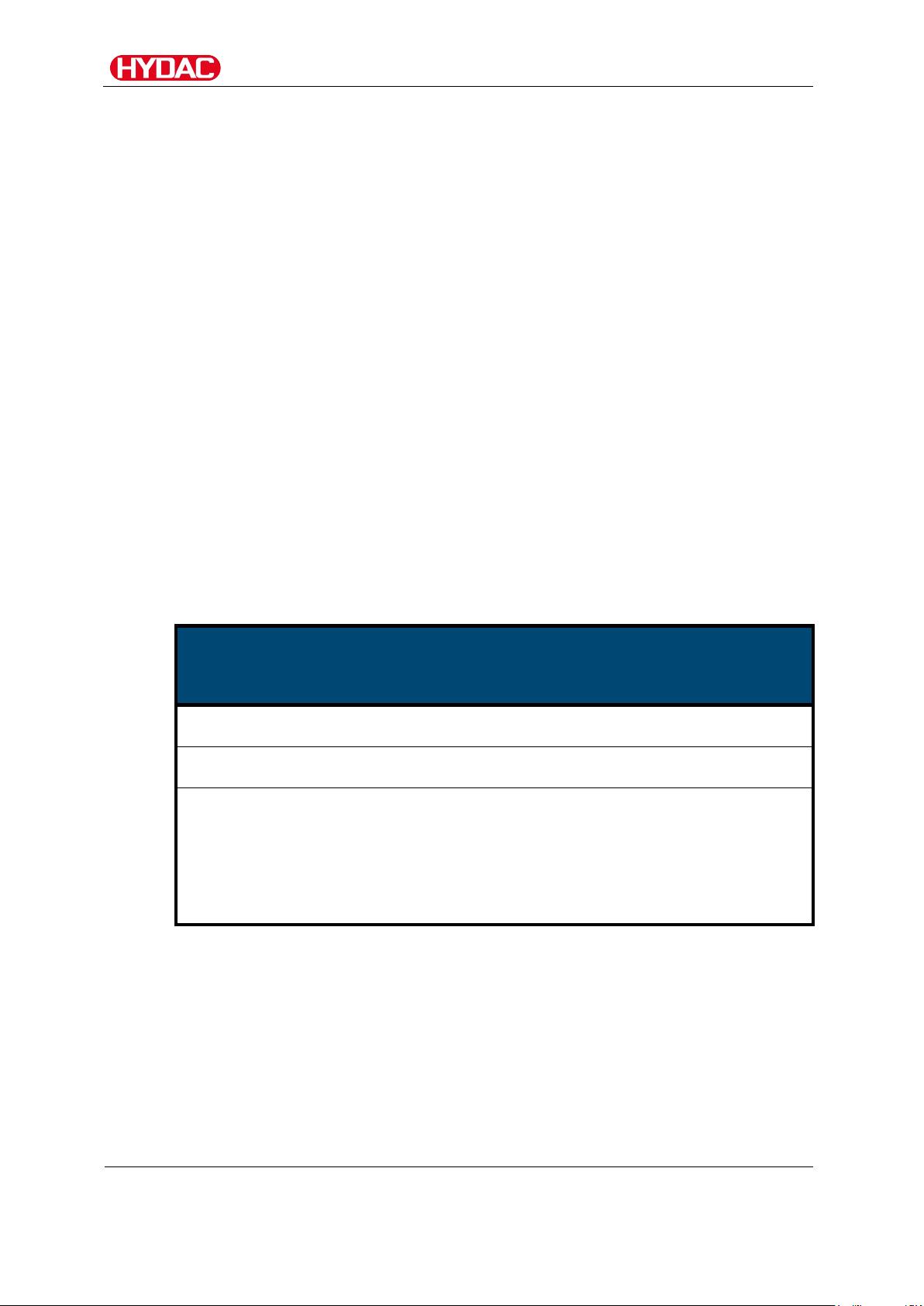
NOTICE
Impermissible operating media/conditions
The sensor will be damaged
► Use the sensor only in conjunction with mineral and synthetic oils
(for example: poly-alpha-olefins PAO and polyglycol, as used in the
wind energy industry).
► Note that the media used must be permanently compatible with the
MCS sealing material.
MCS /-C062
BeWa MCS1000-C062 4366964 C0930x en-us 2018-06-
25.docx
en(us)
Page 11 / 76
2018-06-25
Page 12

Safety Information
Improper Use or Use Deviating from Intended Use
Any use extending beyond this or deviating therefrom shall not be considered
intended use. HYDAC FILTER SYSTEMS GMBH will assume no liability for
any damage resulting from such use. The user alone, shall assume any and
all associated risk.
Improper use or use deviating from intended may result in hazards and/or will
damage the sensor. Examples of improper use:
• Operation with a non-approved medium.
• Operation under impermissible operating conditions.
• Modifications to the sensor made by the user or purchaser.
MCS /-C062
BeWa MCS1000-C062 4366964 C0930x en-us 2018-06-
25.docx
en(us)
Page 12 / 76
2018-06-25
Page 13

Safety Information
Activity
Person
Knowledge
Transport / storage
Forwarding
• No specialist knowledge
Hydraulic / electrical
Specialist
• Safe handling/use of tools
Operation
Specialist
• Product-specific knowledge
Disposal
Specialist
• Knowledge about reuse
Qualifications of personnel / target group
Persons who work on the sensor must be aware of the associated hazards
when using it.
Auxiliary and specialist personnel must have read and understood the
operating instructions, in particular the safety information and instructions,
and applicable regulations before beginning work.
The operating instructions and applicable regulations are to kept so they are
accessible for operating and specialist personnel.
These operating instructions are intended for:
Auxiliary personnel: such persons have been instructed about the sensor
and are aware of potential hazards due to improper use.
Specialist personnel: such persons with corresponding specialist training
and several years' work experience. They are able to assess and perform the
work assigned to them, they are also able to recognize potential hazards.
installation,
First commissioning,
Maintenance,
Troubleshooting,
Repair,
decommissioning,
Disassembly
Operations control
agent
Auxiliary
personnel
personnel
personnel
personnel
required
• Fitting and connection of
hydraulic tubes and
connections
• Fitting and connection of
electrical lines, electrical
machinery, sockets, etc.
• Product-specific knowledge
• Knowledge about how to
handle operating media.
MCS /-C062
BeWa MCS1000-C062 4366964 C0930x en-us 2018-06-
25.docx
en(us)
Page 13 / 76
2018-06-25
Page 14
Transporting the sensor
Transporting the sensor
Transport the sensor upright or on its side, and in the included packaging if
possible. Make sure the connection plug will not be subjected to any
mechanical strain or impact.
Unsafe transport
The connection plug will be damaged
► Transport the sensor in its original packaging.
► Secure the sensor during transport.
NOTICE
Storing the sensor
Store the sensor in a clean, dry place, in the original packing, if possible. Do
not remove the packing until you are ready to install the unit.
For storage conditions, refer to the chapter "Technical Data" on page 67.
MCS /-C062
BeWa MCS1000-C062 4366964 C0930x en-us 2018-06-
25.docx
en(us)
Page 14 / 76
2018-06-25
Page 15
Decoding the model code label
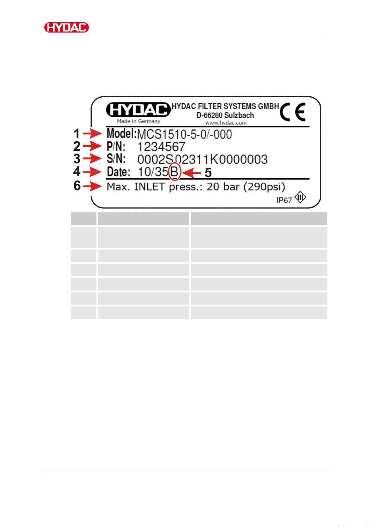
Row
Definition
Description
1
Model
Model according to model code,
2
P/N
p/no.
3
S/N
Serial-no.
4
Date
Year/week of production
5
Index
Hardware index
6
Max. INLET press
Maximum operating pressure
Decoding the model code label
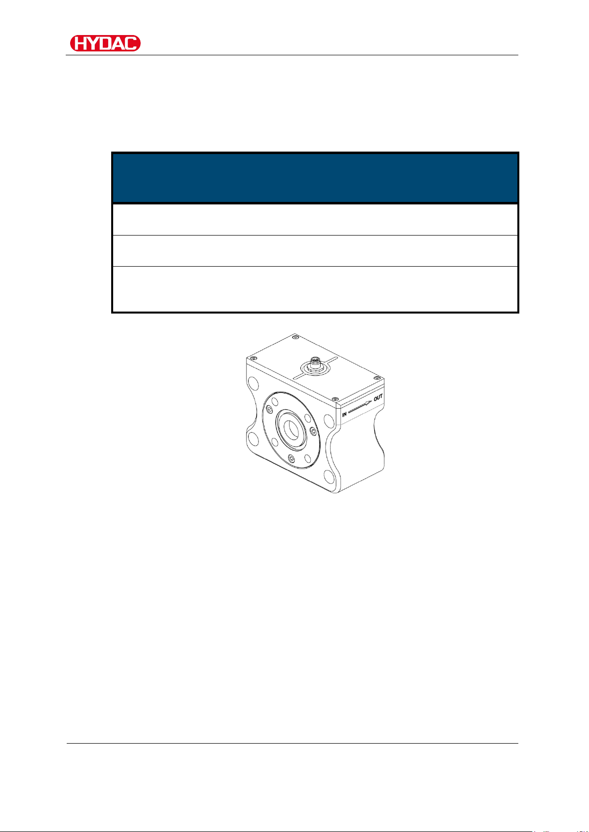
For identification details of the MetallicContamination Sensor, see the type
label. This is located on the top of the unit and contains the exact product
description and the serial number.
for details, see page 69.
MCS /-C062
BeWa MCS1000-C062 4366964 C0930x en-us 2018-06-
25.docx
en(us)
Page 15 / 76
2018-06-25
Page 16
Checking the scope of delivery
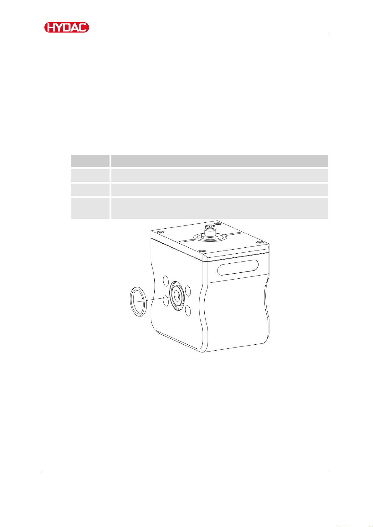
Qty
Designation
1
MetallicContamination Sensor, MCS 13xx
1
O-ring (18.7 x 3.53 NBR 70 Shore)
1
Operation and Installation Guide (this document)
Checking the scope of delivery
The scope of delivery for the available sizes varies. Below is the scope of
delivery for each size.
Scope of delivery for MCS 13xx
The MetallicContamination Sensor MCS 13xx comes packed and factoryassembled. Before commissioning the sensor, please check no items are
missing from the package.
The following items are supplied:
EC declaration of conformity
MCS /-C062
BeWa MCS1000-C062 4366964 C0930x en-us 2018-06-
25.docx
en(us)
Page 16 / 76
2018-06-25
Page 17
Checking the scope of delivery
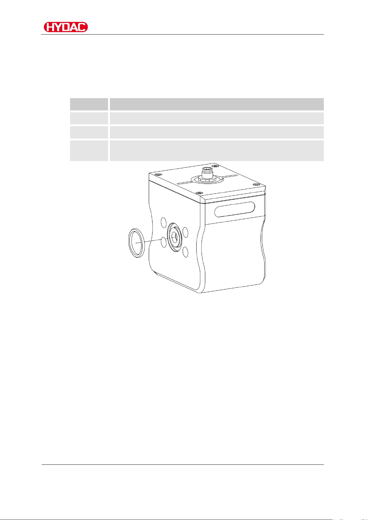
Qty
Designation
1
MetallicContamination Sensor, MCS 14xx
1
O-ring (25 x 3.53 NBR 70 Shore)
1
Operation and Installation Guide (this document)
Scope of delivery for MCS 14xx
The MetallicContamination Sensor MCS 14xx comes packed and factoryassembled. Before commissioning the sensor, please check no items are
missing from the package.
The following items are supplied:
EC declaration of conformity
MCS /-C062
BeWa MCS1000-C062 4366964 C0930x en-us 2018-06-
25.docx
en(us)
Page 17 / 76
2018-06-25
Page 18
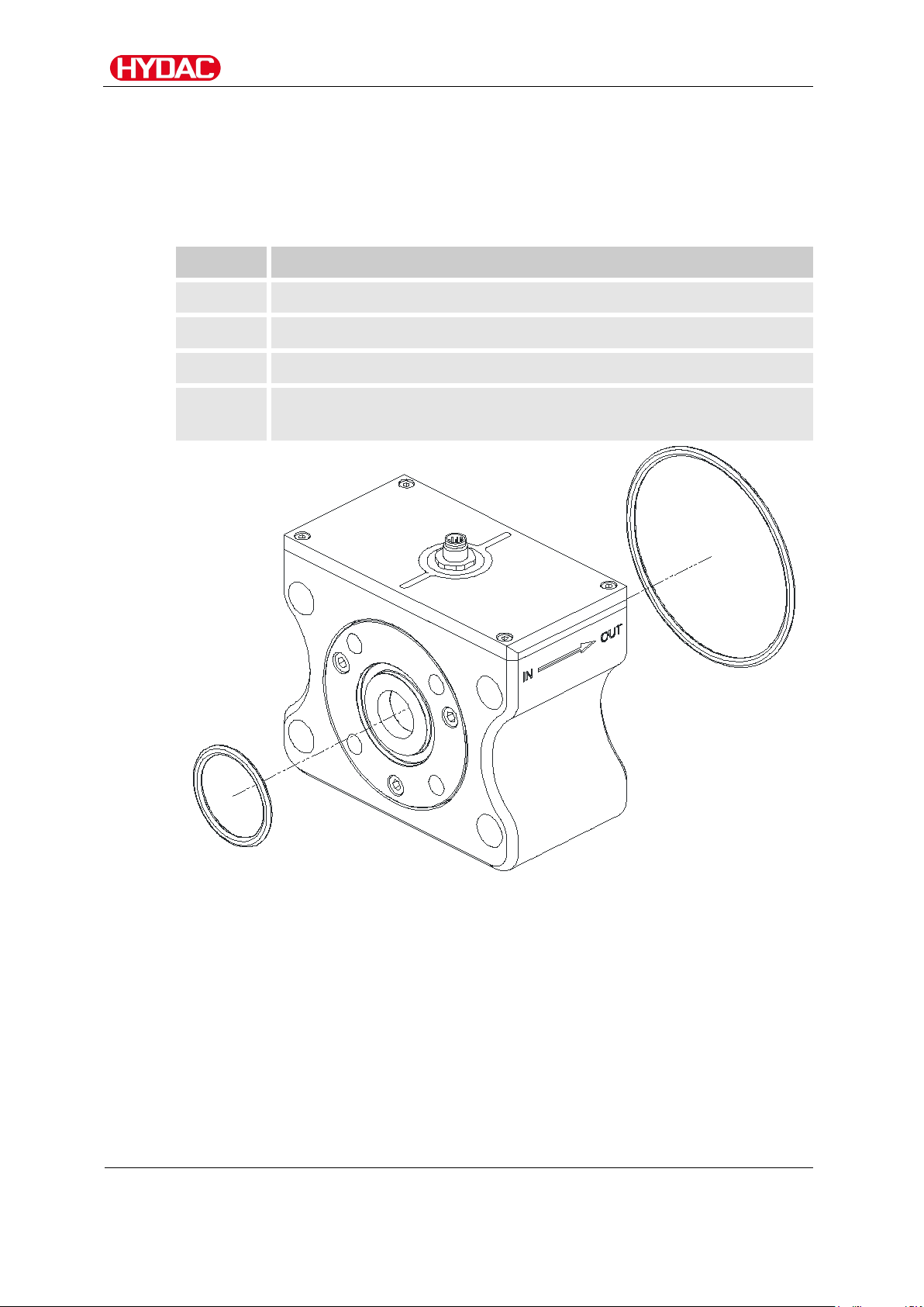
Checking the scope of delivery
Qty
Designation
1
MetallicContamination Sensor, MCS 15xx
1
O-ring (47.22 x 3.53 NBR 70 Shore)
1
O-ring (110.72 x 3.53 NBR 70 Shore)
1
Operation and Installation Guide (this document)
Scope of delivery for MCS 15xx
The MetallicContamination Sensor MCS 15xx comes packed and factoryassembled. Before commissioning the sensor, please check no items are
missing from the package.
The following items are supplied:
EC declaration of conformity
MCS /-C062
BeWa MCS1000-C062 4366964 C0930x en-us 2018-06-
25.docx
en(us)
Page 18 / 76
2018-06-25
Page 19

Sensor features
Sensor features
The MetallicContamination Sensor MCS is a stationary sensor for continuous
monitoring of contamination of fluids – especially lubrication fluids – with
metallic particles.
With appropriate system knowledge of the monitored system, damage
resulting in detectable metallic particles can be discovered early.
The MCS uses digital signal processing to distinguish between ferromagnetic
(Fe) and non-ferromagnetic (nFe) particles.
Particle results are signaled via two switching outputs. In the factory setting
(default values), the ferromagnetic (Fe) particles are output via the first
switching output and the non-ferromagnetic (nFe) particles via the second
switching output. It is possible to make a switch in the menu so that the first
switching output is used for the total particles (Fe and nFe) and second
switch output is used as a "device ready signal". (For this, see also the
chapter Using switching output.)
In addition, the MCS has serial communication interfaces with which
connection to superordinate monitoring systems is possible.
The MCS is intended for incorporation in low-pressure circuits and test
benches.
Functional principle
Within the sensor, a high-frequency magnetic field is generated using a coil
system. Two sensor pulses measure changes in the field strength and output
certain signals as described below.
• A ferromagnetic (Fe) particle, the field strength increases depending
on the size of the particle.
• A non-ferromagnetic (nFe) particle, the field strength decreases
depending on the size of the particle.
• If a prespecified limit is exceeded, a particle event is signaled.
• The MCS is able to implement variable adjustments to the defined limit
in order to avoid faulty particle counter results. This makes it possible
to suppress the results for Dimension A and D temporarily (Noise
Suppression) in the event of a very strongly fluctuating field strength
(e.g. following excessive air intake into the system).
The output signal at the switching output is always the same and provides no
information about the size of the particle.
Using the serial interfaces (RS 485 or HSI) makes it possible to evaluate
appropriate particle size classes.
MCS /-C062
BeWa MCS1000-C062 4366964 C0930x en-us 2018-06-
25.docx
en(us)
Page 19 / 76
2018-06-25
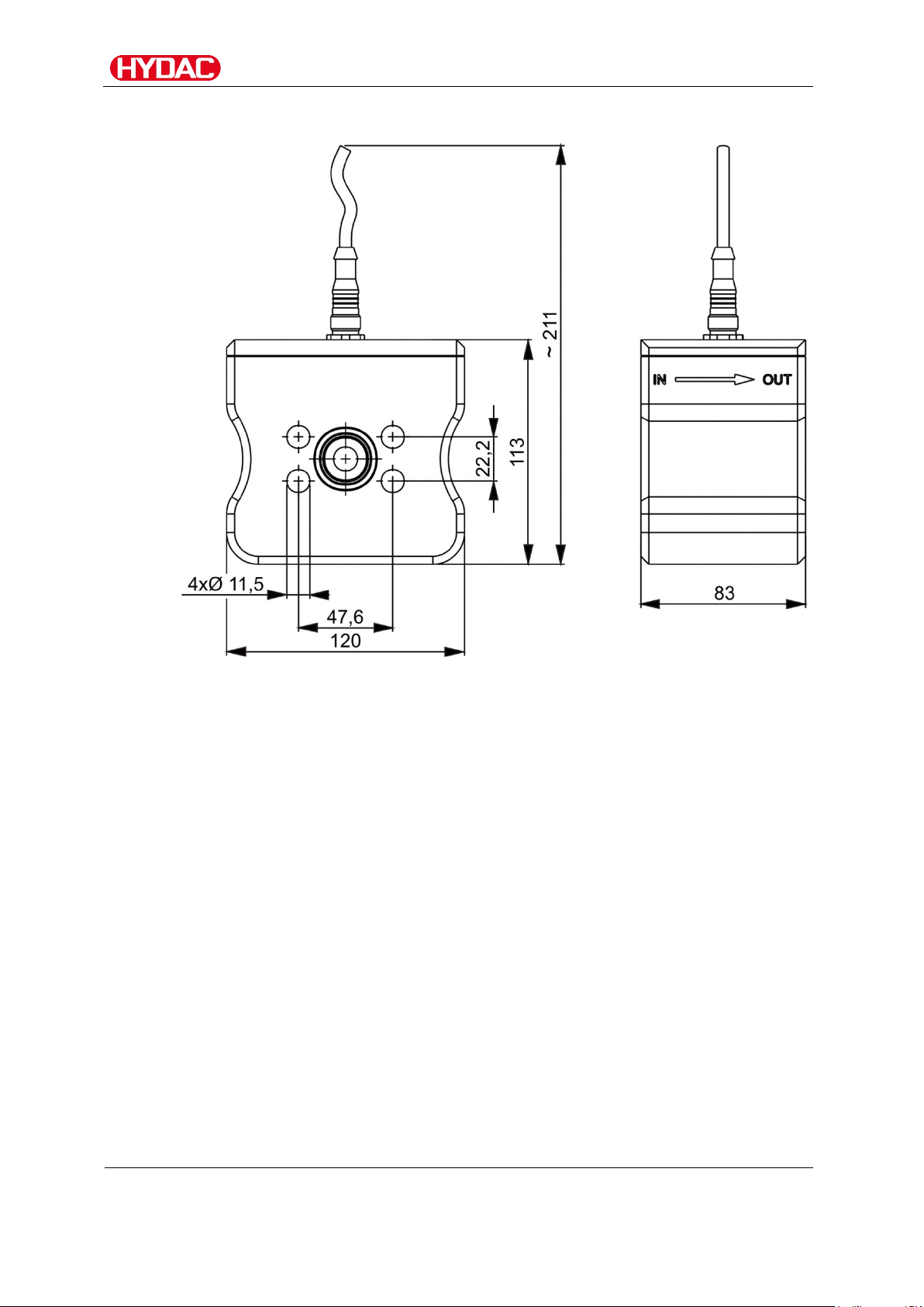
Page 20
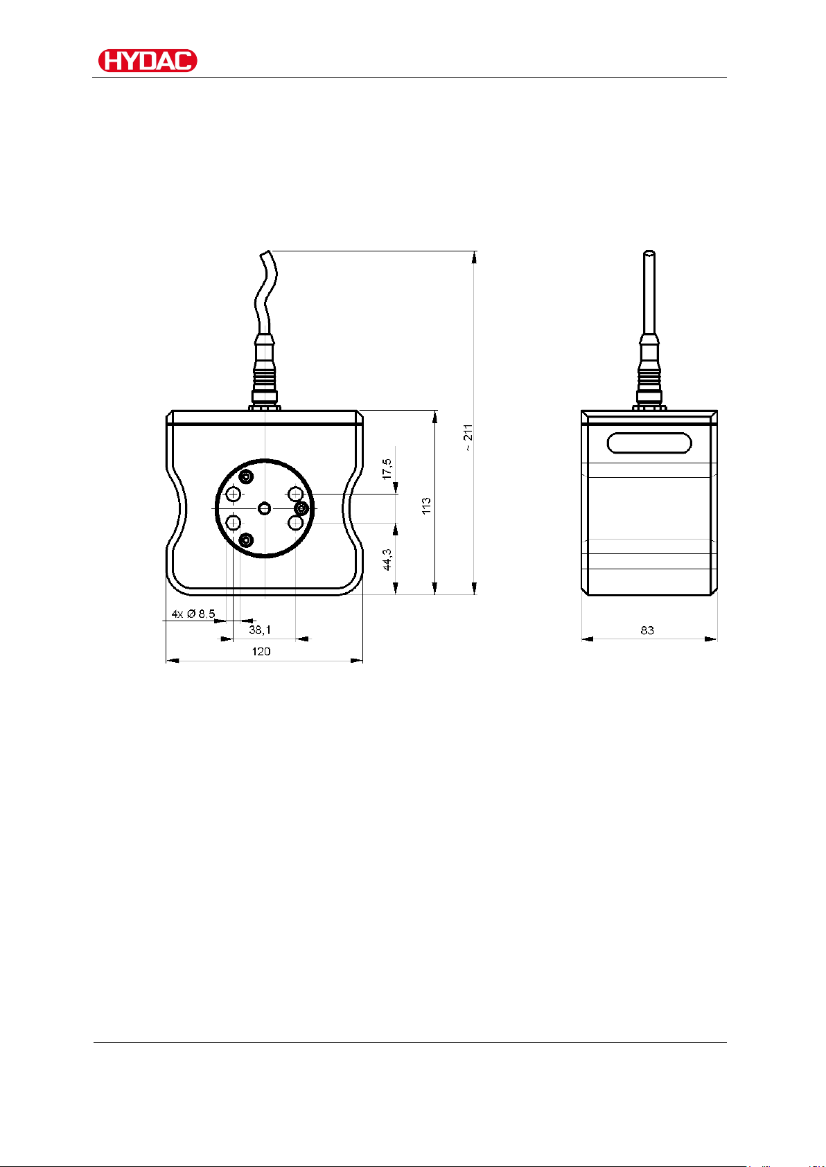
Sensor dimensions
All dimensions in mm.
Sensor dimensions
The dimensions for the available sizes vary. The dimensions for each size
can be found below.
Dimensions MCS 13xx
Flange image SAE 1/2"
MCS /-C062
BeWa MCS1000-C062 4366964 C0930x en-us 2018-06-
25.docx
en(us)
Page 20 / 76
2018-06-25
Page 21
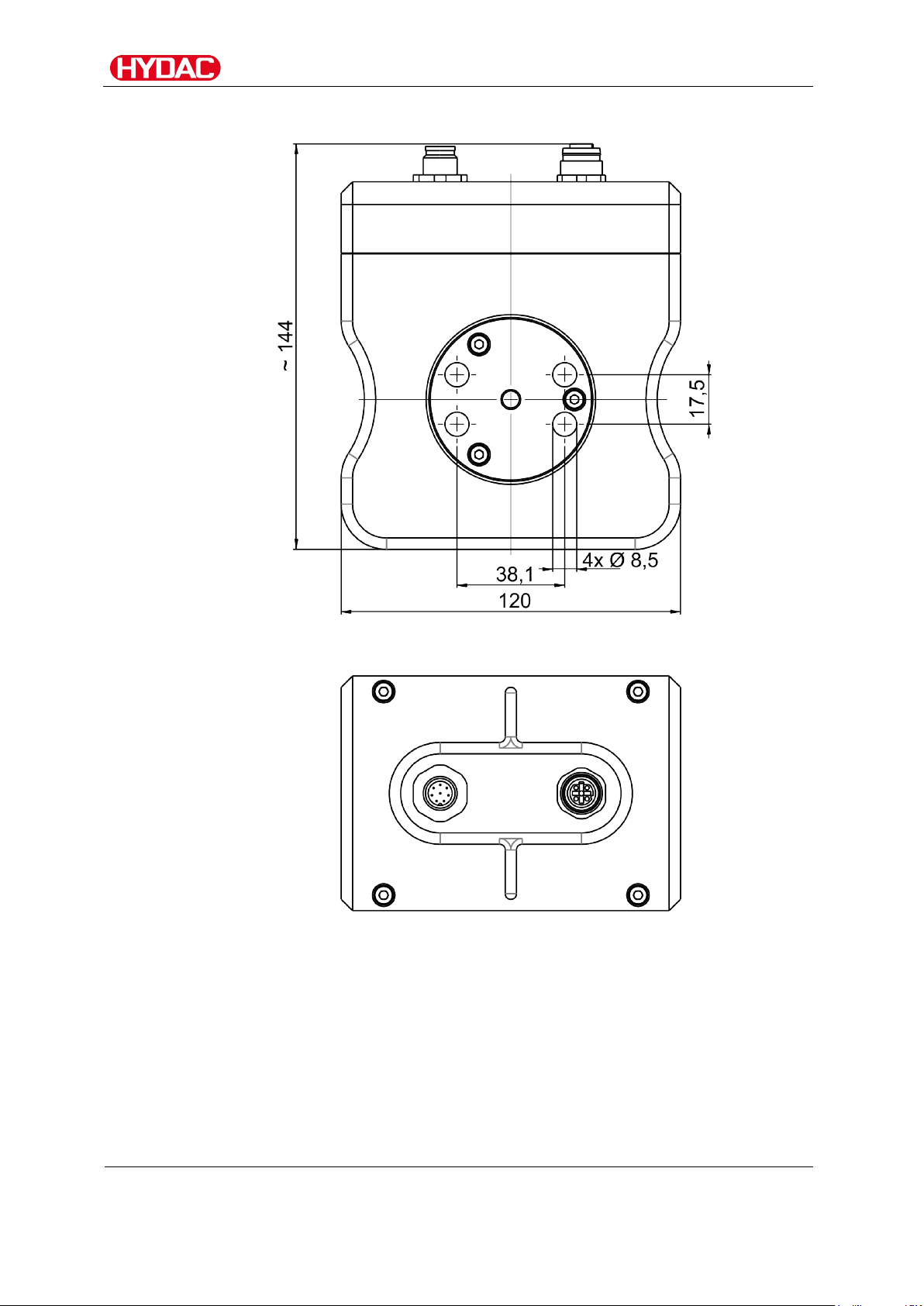
Sensor dimensions
All dimensions in mm.
Dimensions for MCS 13xx with Ethernet module
Flange image SAE 1/2"
MCS /-C062
BeWa MCS1000-C062 4366964 C0930x en-us 2018-06-
25.docx
en(us)
Page 21 / 76
2018-06-25
Page 22
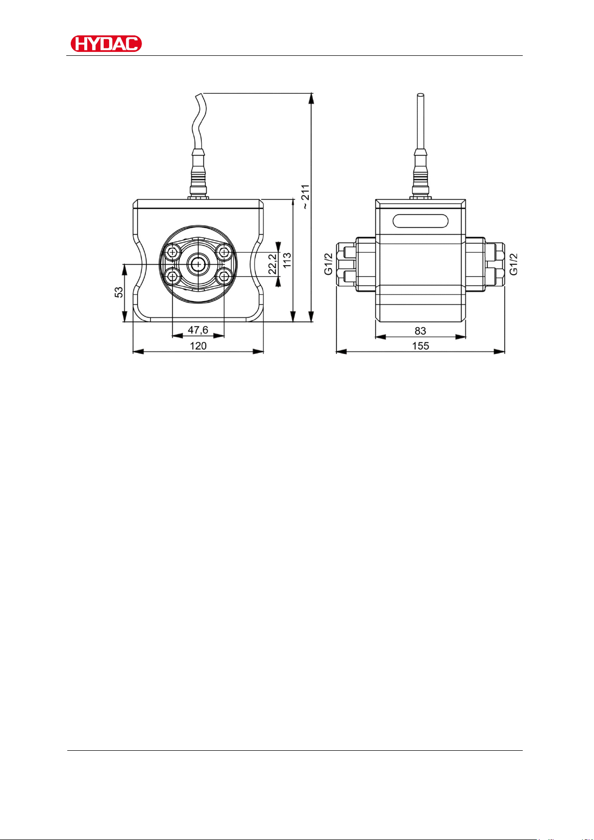
Sensor dimensions
All dimensions in mm.
Dimensions MCS 13xx with flange adapter set (optional accessories)
MCS /-C062
BeWa MCS1000-C062 4366964 C0930x en-us 2018-06-
25.docx
en(us)
Page 22 / 76
2018-06-25
Page 23
Sensor dimensions
All dimensions in mm.
Dimensions MCS 14xx
Flange image SAE 3/4"
MCS /-C062
BeWa MCS1000-C062 4366964 C0930x en-us 2018-06-
25.docx
en(us)
Page 23 / 76
2018-06-25
Page 24

Sensor dimensions
All dimensions in mm.
Dimensions for MCS 14xx with Ethernet
Flange image SAE 3/4"
MCS /-C062
BeWa MCS1000-C062 4366964 C0930x en-us 2018-06-
25.docx
en(us)
Page 24 / 76
2018-06-25
Page 25

Sensor dimensions
All dimensions in mm.
Dimensions MCS 14xx with flange adapter set (optional accessories)
MCS /-C062
BeWa MCS1000-C062 4366964 C0930x en-us 2018-06-
25.docx
en(us)
Page 25 / 76
2018-06-25
Page 26

Sensor dimensions
All dimensions in mm.
Dimensions MCS 15xx
Flange image SAE 4"
MCS /-C062
BeWa MCS1000-C062 4366964 C0930x en-us 2018-06-
25.docx
en(us)
Page 26 / 76
2018-06-25
Page 27

Sensor dimensions
All dimensions in mm.
Dimensions for MCS 15xx with Ethernet
Flange image SAE 3/4"
MCS /-C062
BeWa MCS1000-C062 4366964 C0930x en-us 2018-06-
25.docx
en(us)
Page 27 / 76
2018-06-25
Page 28

Sensor dimensions
All dimensions in mm.
Dimensions MCS 15xx with flange adapter set (optional accessories)
MCS /-C062
BeWa MCS1000-C062 4366964 C0930x en-us 2018-06-
25.docx
en(us)
Page 28 / 76
2018-06-25
Page 29

Mechanical installation/assembly
Mechanical installation/assembly
During installation, always observe the direction of flow through the sensor.
The direction of flow is indicated by an arrow on the housing.
When selecting the installation site, take ambient factors like the
temperature, dust, water, etc., into account.
The sensor is designed for IP67 according to DIN 40050 / EN 60529 / IEC
529 / VDE 0470.
The sensor offers various options for mechanical installation. Below you can
find the possible mechanical installations permitted.
MCS /-C062
BeWa MCS1000-C062 4366964 C0930x en-us 2018-06-
25.docx
en(us)
Page 29 / 76
2018-06-25
Page 30

Mechanical installation/assembly
Connecting MCS13xx / 14xx via flange adapter set
A flange adapter set is available as an accessory. You will find the part no. in
the "Spare Parts and Accessories" chapter on page 63.
This flange adapter set makes it possible for you to connect the MCS directly
to two pipes or hoses via the thread G1/2".
MCS /-C062
BeWa MCS1000-C062 4366964 C0930x en-us 2018-06-
25.docx
en(us)
Page 30 / 76
2018-06-25
Page 31

Fastening sensor to underside
Fastening sensor to underside
The sensors have 4 fixing holes on the underside. Use these to secure the
MCS.
MCS /-C062
BeWa MCS1000-C062 4366964 C0930x en-us 2018-06-
25.docx
en(us)
Page 31 / 76
2018-06-25
Page 32

Fastening sensor to underside
Fastening MCS 13xx / MCS 14xx
Below you can see the drilling template for fastening the MCS 13xx/14xx.
(All dimensions in mm)
Fastening MCS 15xx
Below you can see the drilling template for fastening the MCS 13xx/14xx.
(All dimensions in mm)
MCS /-C062
BeWa MCS1000-C062 4366964 C0930x en-us 2018-06-
25.docx
en(us)
Page 32 / 76
2018-06-25
Page 33

Fastening sensor to underside
Fastening MCS 15xx using angle fastening set
An angle fastening set is available as an accessory. HYDAC article no.
3477243.
Connecting MCS 15xx using pipe adapter set
A pipe adapter set is available as an accessory. HYDAC article no. 3435426.
This pipe adapter set makes it possible to connect the MCS directly to two
pipes or hoses via the thread 42L per ISO8431-1.
MCS /-C062
BeWa MCS1000-C062 4366964 C0930x en-us 2018-06-
25.docx
en(us)
Page 33 / 76
2018-06-25
Page 34

Fastening sensor to underside
Connecting MCS 15xx using flange adapter plate (accessory)
A flange adapter set is available as an accessory. HYDAC article no.
3442518.
With the flange adapter set SAE4"-SAE1½" (1) you have the opportunity to
mount the MCS between the filter unit and the pump. The flange adapter
plate offers three ¼" connections for the integration of more sensors.
Example: installation in the filter cooling circuit between pump and partial flow
filter.
MCS /-C062
BeWa MCS1000-C062 4366964 C0930x en-us 2018-06-
25.docx
en(us)
Page 34 / 76
2018-06-25
Page 35

Fastening sensor to underside
MCS 15xx via SAE 4" per ISO 6162-1 (4xM16)
Install the MCS with four screws (M16) to a component/unit. The drilling
template corresponds to the SAE 4" per ISO 6162-1.
Example: installing the MCS on an NF filter
MCS /-C062
BeWa MCS1000-C062 4366964 C0930x en-us 2018-06-
25.docx
en(us)
Page 35 / 76
2018-06-25
Page 36

Hydraulic installation of sensor
Q l/min
Hydraulic installation of sensor
During installation, observe the direction of flow through the MCS. The
direction of flow is indicated by an arrow on the housing.
NOTICE
Exceeding the permissible operating pressure
The sensor will be destroyed
► Note the maximum operating pressure of 20 bar / 290 psi.
Diagram - flow rate, differential pressure p∆ and viscosity ν
Observe the measured volumetric flow rate. For the MCS14xx this is
between 2 and 40 l/min and for the MCS15xx between 10 and 200 l/min. For
flow rates outside these limits, a detection of particles is no longer
guaranteed.
∆P mbar
MCS /-C062
BeWa MCS1000-C062 4366964 C0930x en-us 2018-06-
25.docx
en(us)
Page 36 / 76
2018-06-25
Page 37

Hydraulic installation of sensor
Q l/min
Q l/min
∆P mbar
∆P mbar
The diagram shows the resulting differential pressurep∆mbar as a function
of the flow rate Q l/min at different viscosities.
MCS /-C062
BeWa MCS1000-C062 4366964 C0930x en-us 2018-06-
25.docx
en(us)
Page 37 / 76
2018-06-25
Page 38

Electrical connection of sensor
Pin
Assignment
1
Supply voltage 9-36 V DC
2
Switch output 2 (normally open)
3
GND for supply voltage
4
GND switching output
5
HSI (HYDAC Sensor Interface)
6
RS485 +
7
RS485 -
8
Switch output 1 (normally open)
Electrical connection of sensor
Plug pin assignment
The two switching outputs are in each case a passive, n-switching power
MOSFET.
The switching outputs are open without current. There is contact between the
plug housing and the housing.
MCS /-C062
BeWa MCS1000-C062 4366964 C0930x en-us 2018-06-
25.docx
en(us)
Page 38 / 76
2018-06-25
Page 39

Electrical connection of sensor
Pin
Color
Connection to
1
White
Supply voltage 9-36 V DC
2
brown
Switching output 2
3
Green
GND supply voltage
4
Yellow
GND switching output
5
grey
HSI (HYDAC Sensor Interface)
6
Pink
RS485 +
7
Blue
RS485 -
8
Red
Switching output 1
Shield
-
Shield
Connection cable - Assignment / Color coding
In the accessories list you will find connection cables of various lengths with
one connection plug (M12x1, 8-pole, according to DIN VDE 0627) and an
open end.
In the table below you will find the color coding of the HYDAC accessory
cable ZBE42-xx:
(All dimensions in mm)
MCS /-C062
BeWa MCS1000-C062 4366964 C0930x en-us 2018-06-
25.docx
en(us)
Page 39 / 76
2018-06-25
Page 40

Using the switching outputs
Particle
Switching output
ferromagnetic (Fe)
=
1
non-ferromagnetic (nFe)
=
2
Particle
Switching output
ferromagnetic (Fe)
non-ferromagnetic (nFe)
Device Ready
=
2
Particle
Switching output
Alarm
=
1
Device Ready
=
2
Using the switching outputs
The two switching outputs delivery pulses that can be counted or utilized in a
superordinate controller.
The logic of the signal outputs is parameterizable. You can select between
"active low" and "active high" (factory setting).
Details on setting the switching outputs can be found starting on page 53.
Choose among the following settings for the switching output:
Switching output - FE.NFE
A signal for all ferromagnetic (Fe) particles is output at switching output 1,
and a signal for all non-ferromagnetic (nFe) particles at switching output 2.
Switching output - ALL.RDY (factory setting)
A signal for all ferromagnetic (Fe) particles and all non-ferromagnetic (nFe)
particles is output at switching output 1.
The switching output 2 outputs the "Device Ready" signal indicating
readiness for use.
and
= 1
Switching output - ALARM
A warning is output on switching output 1 for the set threshold. Set the limit
values as stated in the "ALARM – Setting limit values" chapter on page 55.
The switching output 2 outputs the "Device Ready" signal indicating
readiness for use.
MCS /-C062
BeWa MCS1000-C062 4366964 C0930x en-us 2018-06-
25.docx
en(us)
Page 40 / 76
2018-06-25
Page 41

Using the switching outputs
Note that after the sensor has been switched on or after voltage
0 V
0
U
t
70 s≈
U
M1/2
Δt
0 V
0
U
t
U
M1/2
Switching logic "active low"
Both switching outputs emit a currentless signal when a particle is detected.
You can set the duration of the signal between 5 and 200 ms.
This value is factory set to 7 ms.
The signal gives no indication of the shape and size of the particles.
has returned, a start-up phase of ≈ 70 seconds is necessary
before the first measurement can be made.
Example: Operation - 1 particle detected
Example: Operation - no particle detected
MCS /-C062
BeWa MCS1000-C062 4366964 C0930x en-us 2018-06-
25.docx
en(us)
Page 41 / 76
2018-06-25
Page 42

Using the switching outputs
0 V
0
U
M1/2
U
t
Δt
Δt Δt
Example: Operation - several particles detected
MCS /-C062
BeWa MCS1000-C062 4366964 C0930x en-us 2018-06-
25.docx
en(us)
Page 42 / 76
2018-06-25
Page 43

Using the switching outputs
Note that after the sensor has been switched on or after voltage
0 V
0
U
M1/2
U
t
≈70 s
Δt
≈3 s
0 V
0
U
t
U
M1/2
Switching logic "active high"
Both switching outputs emit a signal when a particle is detected.
You can set the duration of the signal Δt between 5 and 200 ms.
This value is factory set to 7 ms.
The signal gives no indication of the shape and size of the particles.
has returned, a start-up phase of ≈ 70 seconds is necessary
before the first measurement can be made.
Example: Operation - 1 particle detected
Example: Operation - no particle detected
MCS /-C062
BeWa MCS1000-C062 4366964 C0930x en-us 2018-06-
25.docx
en(us)
Page 43 / 76
2018-06-25
Page 44

Using the switching outputs
0 V
0
U
M1/2
U
t
Δt
Δt
Δt
0 V
0
U
M1/2
U
t
≈ 70 s
Example: Operation - several particles detected
Switching output "Device Ready"
When "Device Ready" is set, the buzzer signal of the ferromagnetic and nonferromagnetic particles is emitted on the switching output S1.
The signal indicating that the MCS is ready for use is emitted on the
switching output S2. The signal is always emitted in the same way regardless
of the switching logic "active low" or "active high".
Note that after the sensor has been switched on and after voltage has
returned after an interruption, a start-up phase of ≈ 70 seconds is necessary
before the signal can be evaluated.
After that, the switching output "Device Ready" goes to permanent "low"
potential.
MCS /-C062
BeWa MCS1000-C062 4366964 C0930x en-us 2018-06-
25.docx
en(us)
Page 44 / 76
2018-06-25
Page 45

Parameterizing sensor/reading measured values
Parameterizing sensor/reading measured values
Connecting MCS 1000 to SMU 1200
The MCS 1000 can be connected to the HYDAC SensorMonitoring Unit
SMU 1200.
The SMU1200 makes it possible to:
• set parameters
• save the MCS measurement data with a time stamp
• read off stored data via USB memory stick
• forward the online measurement data to a PC
• forward the switching outputs to a superordinate controller
You can find more details in the SMU 1200 operating instructions.
MCS /-C062
BeWa MCS1000-C062 4366964 C0930x en-us 2018-06-
25.docx
en(us)
Page 45 / 76
2018-06-25
Page 46

Parameterizing sensor/reading measured values
USB-A
USB-B
PS2
PC
CSI-D-5
MCS 1000
ZBE 43-05
CSI-D-5 Kit
Connecting MCS to CSI-D-5 (Condition Sensor Interface)
With the CSI-D-5 kit you have the opportunity to parameterize the MCS using
a PC and to read off online and stored measurement data.
Connect the CSI-D-5 kit, HYDAC article no. 3249563, in accordance with the
following connection diagram:
MCS /-C062
BeWa MCS1000-C062 4366964 C0930x en-us 2018-06-
25.docx
en(us)
Page 46 / 76
2018-06-25
Page 47

Parameterizing sensor/reading measured values
Connecting MCS to HMG 3000
You can use the HMG 3000 to set the parameters of the MCS.
Connect the HMG 3000 to the MCS in accordance with the following
connection diagram.
You can find more details in the HMG 3000 operating instructions.
MCS /-C062
BeWa MCS1000-C062 4366964 C0930x en-us 2018-06-
25.docx
en(us)
Page 47 / 76
2018-06-25
Page 48

Evaluating measurement results
Evaluating measurement results
The counter readings of the MCS are not comparable with particle
concentrations as these are known from optical particle counters per ISO
4406.
If the counter reading stays the same, this does not mean that a constant
particle concentration is present, but rather the no further particles have been
detected.
Occurring particles need not have been generated immediately before being
detected by the sensor. Depending on the system, they may be sedimented
particles that were stirred up by shaking or vibration and then got into the
fluid stream.
For detailed evaluation of the measurement results, it is necessary to know
the following operating parameters of the system:
Is a constant, variable, or only temporarily existent fluid stream through the
sensor present?
Example: During the analysis of the particles occurring each day, the actual
operating duration of the system is to be considered. This can vary
significantly from day to day, for example, in gear transmissions in wind
energy plants.
Is it possible for particles to flow back?
Example: In case of depressurization from an incompletely bled system.
Is a fluid filter present that filters out the particles, or are they conveyed
through the circuit?
Example: Without filtration, an individual particle can be detected several
times by the MCS.
MCS /-C062
BeWa MCS1000-C062 4366964 C0930x en-us 2018-06-
25.docx
en(us)
Page 48 / 76
2018-06-25
Page 49

Menu structure
Power Up Menu
MODE
M2
S.TIME
SEL.COM
HSI
ADRESS
HSI
DEFAULT
CANCEL
SAVE
Menu structure
This chapter gives you an overview of the menu structure of the Power Up
and Measuring menus.
Overview - Power Up Menu
MCS /-C062
BeWa MCS1000-C062 4366964 C0930x en-us 2018-06-
25.docx
en(us)
Page 49 / 76
2018-06-25
Page 50

Menu structure
Measuring menu
DSPLAY
FE A
FE B
FE C
NFE D
NFE E
NFE F
CYC A
CYC B
CYC C
CYC D
CYC E
CYC F
STATUS
FI TEMP C
TEMP F
SWT.OUT
FE.NFE
ALL.RDY
ALARM
SWT.LOG
ACT.HI
ACT.LOW
SWT.PLS
SWT.TST
Type
SWT.FE
SWT.NFE
NUM
START
ALARM
A
PERIOD
LIMIT
B
PERIOD
LIMIT
C
PERIOD
LIMIT
CANCEL
SAVE
Overview - Measuring Menu
MCS /-C062
BeWa MCS1000-C062 4366964 C0930x en-us 2018-06-
25.docx
en(us)
Page 50 / 76
2018-06-25
Page 51

PowerUp Menu
Function:
Adjustment not possible
Parameter:
None
Factory setting:
M2 (Measure and switch)
Function:
After the time interval set, the total number of
be seen from the parameter DSPLAY - CYC.
Parameter:
1 - 120 minutes
Factory setting:
60
Purpose:
Set transfer protocol to the superordinate system
Function:
Adjustment not possible.
Parameter:
None
Factory setting:
HSI
Parameter:
A - Z for the HSI bus
Factory setting:
D
Function:
Reset to the factory settings.
parameter.
Parameter:
None
Parameter:
None
PowerUp Menu
MODE - select operating mode
S.TIME - Set storing interval
particles is written to the memory of the MCS.
The number of particles within the time intervals can
SEL.COM - Set protocol
ADRESS – Set bus address
DFAULT - Reset to factory setting
You can find the factory setting at the corresponding
CANCEL - cancel without saving
SAVE - save changes
MCS /-C062
BeWa MCS1000-C062 4366964 C0930x en-us 2018-06-
25.docx
en(us)
Page 51 / 76
2018-06-25
Page 52

Measuring menu
Function:
Select the measured variable that is displayed after
Parameter:
FE A:
ferromagnetic
Class A
FE B:
ferromagnetic
Class B
FE C:
ferromagnetic
Class C
NFE D:
non-ferromagnetic
Class D
NFE E:
non-ferromagnetic
Class E
NFE F:
non-ferromagnetic
Class F
CYC A:
ferromagnetic
Class A
CYC B:
ferromagnetic
Class B
CYC C:
ferromagnetic
Class C
CYC D:
non-ferromagnetic
Class D
CYC E:
non-ferromagnetic
Class E
Measuring menu
DSPLAY - Show measured variable
switching the unit on and after voltage has returned.
The measured variables FE A to NFE F show a
summation of the particles in the corresponding
category. The counter starts when voltage is
switched on and is reset by the absence of voltage.
The counter readings are stored in the internal
memory after the passage of S.TIME in each case.
The parameter CYC (cycle) gives the number of
particles per variable that were counted within the
current measurement time (parameter S.TIME).
The measuring time begins when the voltage is
switched on or the power-up menu is exited. The
value of the current interval is always displayed.
particles (Fe)
particles (Fe)
particles (Fe)
particles (nFe)
particles (nFe)
particles (nFe)
particles (Fe)
particles (Fe)
particles (Fe)
MCS /-C062
BeWa MCS1000-C062 4366964 C0930x en-us 2018-06-
25.docx
particles (nFe)
particles (nFe)
en(us)
Page 52 / 76
2018-06-25
Page 53

Measuring menu
CYC F:
non-ferromagnetic
Class F
STATUS:
Status byte
FI:
Field strength of the field coil in the MCS
TEMP C:
Medium temperature in °C (indirect
TEMP F:
Medium temperature in °F (indirect
Factory setting:
FE A
Function:
You can find a detailed description on page 40.
Parameter:
FE.NFE
S1 =
ferromagnetic (Fe)
S2 =
Non-ferromagnetic (nFe)
ALL.RDY
S1 =
ferromagnetic (Fe) and nonS2 =
Device Ready
ALARM
S1 =
Alarm
S2 =
Device Ready
Factory setting:
ALL.RDY
particles (nFe)
(00 at status = O.K.)
measurement via sensor in the spool)
measurement via sensor in the spool)
The value of 1000 µm is shown on the display as 1k.
SWT.OUT – Set the switching output
ferromagnetic (nFe)
MCS /-C062
BeWa MCS1000-C062 4366964 C0930x en-us 2018-06-
25.docx
en(us)
Page 53 / 76
2018-06-25
Page 54

Measuring menu
Parameter:
ACT.HI
active high
ACT.LOW
active low
Factory setting:
ACT.HI
Function:
Setting the pulse length of the switching outputs
Parameter:
5 - 200 milliseconds
Factory setting:
7
Function:
Function test of the switching outputs
Parameter:
TYPE
FE = switching output 1
NUM
Number of pulses
START
Start of function test
Factory setting:
TYPE
FE
NUM
5
SWT.LOG - Set logic at the switching output
SWT.PLS - Set pulse length at the switching output
SWT.TST – Set test pulse at the switching output
NFE = switching output 2
MCS /-C062
BeWa MCS1000-C062 4366964 C0930x en-us 2018-06-
25.docx
en(us)
Page 54 / 76
2018-06-25
Page 55

Measuring menu
Function:
Set limit values.
limit value. The alarm indicates that the set limit value
has been exceeded and is not necessarily due to any
Parameter:
PERIOD
10 … 180
LIMIT
5 … 232
PERIOD
2 … 72
LIMIT
20 … 232
PERIOD
3 … 30
LIMIT
100 … 232
Factory setting:
PERIOD
30
LIMIT
20 B PERIOD
24
LIMIT
100
PERIOD
7
LIMIT
500
Parameter:
None
Parameter:
None
ALARM – Setting limit values
The signal is active for 30 seconds after exceeding a
damage to the monitored system.
A – Minute (min)
B – Hours (h)
C – Days (d)
A
C
CANCEL - cancel without saving
SAVE - Save changes
MCS /-C062
BeWa MCS1000-C062 4366964 C0930x en-us 2018-06-
25.docx
en(us)
Page 55 / 76
2018-06-25
Page 56

Error analysis / remedy
Designation
Description
Operation voltage
Voltage for operating the MCS (electronics, coil
Measurement
Voltage U
at switching output 1/2 for superordinate
Signal value
Measurement voltage on = high
Step
Pin
<->
Pin
Description
1 1 <->
3
Check the operation voltage.
2 2 <->
4
Check the measurement voltage UM1 at the
3 8 <->
4
Check the measurement voltage UM2 at the
1
7
6
5
4
3
2
8
Schirm
Shield
Blindage
1
2
3
4
5
6
7
8
Schirm / Shield / B
lindage
weiss / white /
blanc
grün / green /
vert
rosa / pink / rose
blau / blue /
bleu
grau / grey /
gris
braun / brown /
brun
gelb / ye llow /
jaune
rot / red /
rouge
1
2
3
Error analysis / remedy
Using several supply voltages makes it necessary to define the following
terms for error analysis:
system).
voltage
Remove the connection cable on the MCS for error analysis and check the
socket on the connection cable according to the following steps:
controllers.
Measurement voltage off = low
M1/2
switching output 1
switching output 2
MCS /-C062
BeWa MCS1000-C062 4366964 C0930x en-us 2018-06-
25.docx
en(us)
Page 56 / 76
2018-06-25
Page 57

Error analysis / remedy
Status
Remedy
The MCS is switched
measurement voltage
Reestablish the
voltage.
Switching logic
Signal value at
switching output
Step 1
Step 2 / 3
high ON ON
active low
low ON ON Error at MCS Contact HYDAC
low ON ON
active high
high ON ON Error at MCS Contact HYDAC
ON OFF
OFF ON
The MCS has not
detected any particles
The MCS has not
detected any particles
Error in measurement
voltage
The MCS is switched
off; error in operation
voltage
-
-
Reestablish the
measurement
voltage.
Reestablish the
operation voltage.
MCS /-C062
BeWa MCS1000-C062 4366964 C0930x en-us 2018-06-
25.docx
OFF OFF
off; error in operation
voltage /
operation and
measurement
en(us)
Page 57 / 76
2018-06-25
Page 58

Error analysis / remedy
1.
Check the operation voltage to the sensor.
2.
Check the measurement voltage (U
) to the sensor.
3.
Perform a reset. Remove the connection cable of the MCS for 10
4.
If there is no change in the error status, contact HYDAC.
0 V
0
U
t
U
M1/2
Operation voltage
ON
Measurement voltage U
ON or OFF
Error status - "active high" and "active low"
In "active high" and "active low" operation, two errors can occur.
In case of error, proceed as follows:
M1/2
seconds. Reconnect the connection cable to the MCS.
Observe the starting phase of ≈ 70 seconds.
Error status 1 "active low"
The signal at the switching output is permanently free of voltage. The MCS
has detected an error.
M1/2
MCS /-C062
BeWa MCS1000-C062 4366964 C0930x en-us 2018-06-
25.docx
en(us)
Page 58 / 76
2018-06-25
Page 59

Error analysis / remedy
0 V
0
U
t
U
M1/2
Operation voltage
ON or OFF
Measurement voltage U
ON
Error status 1 "active high"
The signal at the switching output is permanently voltage-carrying. The MCS
has detected an error.
This error occurs also when operation voltage is switched off and
measurement voltage is switched on.
M1/2
MCS /-C062
BeWa MCS1000-C062 4366964 C0930x en-us 2018-06-
25.docx
en(us)
Page 59 / 76
2018-06-25
Page 60

Error analysis / remedy
0 V
0
U
t
U
M1/2
Operation voltage
OFF
Measurement voltage U
ON
Error status 2 "active low"
The signal at the switching output is permanently voltage-carrying. The MCS
has not detected any errors.
This error occurs also when operation voltage is switched off and
measurement voltage is switched on.
Only a superordinate controller can differentiate between this error signal and
normal operation without detection of a particle. Evaluate the signal duration
and the behavior of the two switching outputs S1 and S2 separately.
M1/2
MCS /-C062
BeWa MCS1000-C062 4366964 C0930x en-us 2018-06-
25.docx
en(us)
Page 60 / 76
2018-06-25
Page 61

Error analysis / remedy
0 V
0
U
t
U
M1/2
Operation voltage
ON
Measurement voltage U
OFF
0 V
0
U
M1/2
U
t
Error status 2 "active high"
The signal at the switching output is permanently free of voltage. The MCS
has not detected any errors.
This error occurs also when external measurement voltage is switched off.
Only a superordinate controller can differentiate between this error signal and
normal operation without detection of a particle. Evaluate the signal duration
and the behavior of the two switching outputs S1 and S2 separately.
M1/2
Error status - "Device Ready"
In the "Device Ready" error status there is a signal change from "low" to
"high"
MCS /-C062
BeWa MCS1000-C062 4366964 C0930x en-us 2018-06-
25.docx
en(us)
Page 61 / 76
2018-06-25
Page 62

Performing maintenance
1.
Remove the electric plug.
2.
Depressurize the unit.
3.
Remove the connected hoses/piping from the sensor.
4.
Remove the sensor.
Performing maintenance
Regularly inspect for leaks.
Replace defective cables, hoses or tubes.
The sensor is maintenance-free.
Decommissioning the sensor
To decommission the unit, proceed as follows:
Disposing of sensor/packaging material
Dispose of the packaging material in an environmentally friendly manner.
After removing the sensor and separating its various materials, dispose of it
in an environmentally friendly manner.
MCS /-C062
BeWa MCS1000-C062 4366964 C0930x en-us 2018-06-
25.docx
en(us)
Page 62 / 76
2018-06-25
Page 63

Spare Parts and Accessories
Spare Parts and Accessories
The following spare parts and accessories are available for the sensor.
Description Qty p/no.
MCS14xx flange adapter set SAE ¾" - G 1/2",
comprised of:
1x SAE flange
1x O-ring (NBR)
4x hexagon screw
1 3588249
MCS15xx pipe adapter set, 42L, consisting of:
2x pipe adapter, 42L
2x O-ring (NBR)
8x cheese-head screw
8x washer
8x snap ring
1 3435426
MCS /-C062
BeWa MCS1000-C062 4366964 C0930x en-us 2018-06-
25.docx
en(us)
Page 63 / 76
2018-06-25
Page 64

Spare Parts and Accessories
Description Qty p/no.
MCS15xx flange adapter set, SAE 4" - SAW 1½",
consisting of:
2x O-ring (NBR)
4x cheese-head screw
4x washer
4x snap ring
4x cheese-head screw
1 3442518
MCS15xx angle plate set, consisting of:
1x angle plate
4x cheese-head screw
8x washer
4x snap ring
4x nut
1 3477243
O-ring (18.7 x 3.53 NBR 70 Shore) 1 3112091
O-ring (18.7 x 3.53 FPM low-temperature 70 Shore) 1 6140581
O-ring (25 x 3.53 NBR 70 Shore) 1 601905
O-ring (25 x 3.53 FPM low-temperature 70 Shore) 1 6140582
O-ring (47.22 x 3.53 NBR 70 Shore) 1 604815
O-ring (47.22 x 3.53 FPM low-temperature 70 Shore) 1 6140584
O-ring (110.72 x 3.53 NBR 70 Shore) 1 603576
MCS /-C062
BeWa MCS1000-C062 4366964 C0930x en-us 2018-06-
25.docx
en(us)
Page 64 / 76
2018-06-25
Page 65

Spare Parts and Accessories
Description Qty p/no.
O-ring (110.72 x 3.53 FPM low-temperature 70 Shore) 1 6140585
Socket plug (female) with 2 m line,
shielded, 8-pole, M12x1
Socket plug (female) with 5 m line,
shielded, 8-pole, M12x1
Extension cable 5 m,
Socket plug (female) 8-pole, M12x1 /
ZBE 42-02
ZBE 42-05
ZBE 43-05
1 3281220
1 3281239
1 3281240
Socket plug (male) 8-pole, M12x1
Socket plug (female) with screw clamp,
8-pole, M12x1
Connection cable – Ethernet,
Length 5 m, Patch
Socket plug 4-pole, M12x1 /
ZBE 44
ZBE 45-05
1 3281243
1 3346100
RJ45 plug
Connection cable – Ethernet,
Length 10 m, Patch
Socket plug 4-pole, M12x1 /
ZBE 45-10
1 3346101
RJ45 plug
CD with: "FluMoS light" software 1 3251484
ConditionSensor Interface CSI-D-5 kit 1 3249563
MCS /-C062
BeWa MCS1000-C062 4366964 C0930x en-us 2018-06-
25.docx
en(us)
Page 65 / 76
2018-06-25
Page 66

Channel default settings
Channel:
Particle
MCS13xx
MCS14xx
MCS15xx
Class A
Fe
70 … 100 µm
100 … 150 µm
200 … 300 µm
Class B
Fe
100 … 150 µm
150 … 200 µm
300 … 500 µm
Class C
Fe
> 150 µm
> 200 µm
> 500 µm
Class D
nFe
200 … 300 µm
300 … 450 µm
550 … 750 µm
Class E
nFe
300 … 400 µm
450 … 600 µm
750 … 1000 µm
Class F
nFe
> 400 µm
> 600 µm
> 1000 µm
Telephone:
+49 6897 509 883
Fax:
+49 6897 509 324
E-mail:
service@hydac.com
Channel default settings
Calibrating the sensor
The sensor does not require regular calibrating.
Customer Service/ Service
Use the following shipping address for repairs:
HYDAC SERVICE GMBH
Friedrichsthaler Straße 15a, Werk 13
66540 Neunkirchen-Heinitz
Germany
MCS /-C062
BeWa MCS1000-C062 4366964 C0930x en-us 2018-06-
25.docx
en(us)
Page 66 / 76
2018-06-25
Page 67

Technical Data
Hydraulic data
MCS13xx
MCS14xx
MCS15xx
Permissible flow rate
0.4 … 8 l/min
2 … 40 l/min
10 … 200 l/mi
Maximum operating
20 bar /
20 bar /
20 bar /
Permitted fluid temperature
-40 … 85°C /
-40 … 85°C /
-40 … 85°C /
Diameter / sensor cross-
1/4“
1/2“
1“
General data
Permitted ambient
-40 … 70°C /
-40 … 70°C /
-40 … 70°C /
Seal material in contact
FPM (low-
FPM (low-
FPM (low-
Mechanical connection
SAE 3/4“
SAE 3/4“
SAE 4“
Protection class to DIN
IP 67
IP 67
IP 67
Weight
≈ 3.0 kg
≈ 2.5 kg
≈ 3.5 kg
Dimensions (L x W x H)
83 x 120 x
83 x 120 x
83 x 162 x
Vibration
10 - 58 Hz
0.75 mm
0.75 mm
0.75 mm
58 - 500 Hz
10 g
10 g
10 g
Shock
40 g
40 g
40 g
Technical Data
n
pressure
range
section
temperature range
with the medium
40050
290 psi
-40 … 185°F
-40 … 170°F
temperature)
290 psi
-40 … 185°F
-40 … 170°F
temperature)
290 psi
-40 … 185°F
-40 … 170°F
temperature)
(4x M16)
MCS /-C062
BeWa MCS1000-C062 4366964 C0930x en-us 2018-06-
25.docx
120 mm
(amplitude)
(acceleration)
en(us)
120 mm
(amplitude)
(acceleration)
140 mm
(amplitude)
(acceleration)
Page 67 / 76
2018-06-25
Page 68

Technical Data
Electrical data
Operation voltage
9 … 36 V DC,
Power consumption
≤ 5 Watt
Electrical outputs
2 configurable switching
1 x Ferromagnetic (Fe) particle
Switching output, loadable
≤ 1.5 A, 40 V DC
RS485 interface
2 wire, half duplex
HSI interface
1 wire, half duplex
Ethernet
10Base-T / 100Base-TX
Storage
Permitted storage
-40 … 80°C / -40 … 176°F
Permitted relative humidity
≤ 95%, non condensing
MCS13xx
MCS14xx
MCS15xx
Particle size - Fe
> 70 µm
> 100 µm
> 200 µm
Particle size - nFe
> 200 µm
> 300 µm
> 550 µm
Particle rate
> 25 / s
> 25 / s
> 25 / s
Residual ripple < 10%
outputs
(n-switching Power
MOSFET, normally open)
temperature range
during storage
1 x Non-ferromagnetic (nFe) particle
or
1 x Particle (Fe + nFe)
1 x Device Ready signal
or
1 x Alarm
1 x Device Ready signal
Detection limits
Particle size = volume-equivalent ball diameter.
MCS /-C062
BeWa MCS1000-C062 4366964 C0930x en-us 2018-06-
25.docx
en(us)
Page 68 / 76
2018-06-25
Page 69

Model Code
MCS
1 5 1 0 - 5 - 0 /
000
Product
Series
Contamination / sensor cross-section
Signal technology
Fluids
Mechanical connection
Electrical connection
Modification number
Model Code
MCS = MetallicContamination Sensor
1 = 1000
3 = Particle >70 µm / 1/4"
4 = Particle >100 µm / 1/2"
5 = Particle >200 µm / 1“
1 2x switching outputs /RS485
(HSI protocol)
7 2x switching outputs/RS485/Ethernet
(HSI TCP/IP protocol)
0 = Mineral and synthetic oils
(particularly used in wind power industry)
1 = Flange connection, SAE 1/2" according to ISO 6162-1
(only for MCS13xx)
2 = Flange connection, SAE 3/4" according to ISO 6162-1
(only for MCS14xx)
5 = Flange connection, SAE 4“ according to ISO 6162-1
(only for MCS15xx)
0 = Male connection M12x1, 8 pole
1 = M12x1 male connection, 8-pole and M12x1 Ethernet, 4-pole
D coded as per IEC61076-2-101
EC declaration of conformity
The CE declaration of conformity can be found in the product's scope of
delivery.
MCS /-C062
BeWa MCS1000-C062 4366964 C0930x en-us 2018-06-
25.docx
en(us)
Page 69 / 76
2018-06-25
Page 70

Glossary
Glossary
Ferromagnetic (Fe)
A "ferromagnetic" material is one that turns into a magnet through the
influence of an external magnetic field. Examples are iron, cobalt, and nickel,
which have this property at room temperature.
These materials differ in their residual magnetism (remanence) after being
removed from the magnetic field. Materials with a high remanence are
described as "magnetically hard" and materials with a low remanence are
called "magnetically weak".
Non-ferromagnetic (nFe)
Many metals used in the industry do not have the above-mentioned
ferromagnetic property. Examples include aluminum alloys, copper, brass as
well as austenitic steels like stainless steel. Such metals are called "nonferromagnetic"; they can be easily checked with a commercially available
permanent magnet. If there is no adhesion, the metal is nFe.
Certification
The Metallic Contamination Sensor MCS 1000, a fluid sensor for detecting
metallic solid particle contamination in lubricating liquids according to the
inductive principle, was certified in February 2010 as an "add on" for
condition monitoring systems in wind power plants.
The certification was provided by Germanischer Lloyd Industrial Services
GmbH.
MCS /-C062
BeWa MCS1000-C062 4366964 C0930x en-us 2018-06-
25.docx
en(us)
Page 70 / 76
2018-06-25
Page 71

Glossary
-
The Guideline for the Certification of Condition Monitoring
This guideline states that the sensors must be able to distinguish
-
Testing criteria
Device design
-
Retrofitting in GL-certified plants
Condition monitoring systems in wind power plants which have already
GL is one of the leading certification
Basics of GL certification
Systems (CMS) for Wind Turbines, Edition 2007.
between ferromagnetic and non-ferromagnetic particles and that the
installation location in the cooling filter circuit is upstream of the filter.
Manufacture
Calibration
Quality planning
Product documentation (comprising data sheet and operating and
maintenance instructions)
Proof of function for the MCS 1000
EMC test
been certified by GL do not lose their certification if the MCS 1000 is
built into the system after certification, as the component itself is
certified.
Germanischer Lloyd Industrial Services GmbH, renewable energies
authorities in the wind energy sector,
performing tests, certification procedures and
approvals for wind power plants and their
components.
MCS /-C062
BeWa MCS1000-C062 4366964 C0930x en-us 2018-06-
25.docx
en(us)
Page 71 / 76
2018-06-25
Page 72

Index
Index
A
Accessories .......................................................... 63
accident prevention .............................................. 11
Adjustment............................................................ 51
ambient temperature ...................................... 11, 67
Assignment ..................................................... 38, 39
Auxiliary personnel ............................................... 13
C
Hydraulic data ...................................................... 67
I
Imprint .................................................................... 2
INLET ................................................................... 15
installation ..................................... 13, 29, 34, 36, 71
installing ............................................................... 35
Interface ..............................................38, 39, 46, 65
IP 67
ISO ........................................................... 35, 48, 69
calibrating ............................................................. 66
Calibration ............................................................ 71
care .................................................................... 2, 7
Connection ..................................................... 39, 65
Connection cable ............................................ 39, 65
Content ................................................................... 3
CSI ................................................................. 46, 65
D
Date ...................................................................... 15
default setting ....................................................... 66
depressurization ................................................... 48
Description................................................ 15, 56, 63
Dimensions ...... 20, 21, 22, 23, 24, 25, 26, 27, 28, 67
DIN ........................................................... 29, 39, 67
Disposal ................................................................ 13
Documentation Representative .............................. 2
DSPLAY ................................................... 50, 51, 52
E
EC declaration of conformity............... 16, 17, 18, 69
Electrical data ....................................................... 68
Error ........................................56, 57, 58, 59, 60, 61
Ethernet ...................................21, 24, 27, 65, 68, 69
M
Maintenance ......................................................... 13
Manufacturer .......................................................... 2
Measure ............................................................... 51
Measurement ................................ 56, 58, 59, 60, 61
Measures .............................................................. 10
measuring ............................................................. 52
Measuring menu ....................................... 49, 50, 52
Menu structure ..................................................... 49
MODE ............................................................. 49, 51
O
OFF ............................................... 57, 58, 59, 60, 61
operating .. 7, 8, 9, 11, 12, 13, 15, 36, 45, 47, 48, 51,
56, 67, 71
Operation .... 1, 11, 12, 13, 16, 17, 18, 41, 42, 43, 44,
56, 58, 59, 60, 61, 68
Operations control ................................................ 13
Overview ........................................................ 49, 50
P
Power consumption .............................................. 68
Protection class .................................................... 67
F
Factory setting .................................... 51, 53, 54, 55
filtration ................................................................. 48
Flange connection ................................................ 69
FluMoS ................................................................. 65
Forwarding agent .................................................. 13
G
gear ...................................................................... 48
Glossary ............................................................... 70
GND ............................................................... 38, 39
Guideline .............................................................. 71
H
half duplex ............................................................ 68
Hardware .............................................................. 15
Hazard symbol ...................................................... 10
HSI .................................... 19, 38, 39, 49, 51, 68, 69
MCS /-C062
BeWa MCS1000-C062 4366964 C0930x en-us 2018-06-
25.docx
Remedy ................................................................ 57
repairs .................................................................. 66
SAE ........... 20, 21, 23, 24, 26, 27, 35, 63, 64, 67, 69
Scope of delivery ...................................... 16, 17, 18
select .......................................................... 8, 40, 51
Sensor .. 1, 11, 15, 16, 17, 18, 19, 20, 38, 39, 46, 69,
Serial-no ............................................................... 15
Service ................................................................. 66
setting ....................................................... 19, 40, 51
Signal word ........................................................... 10
signal words ......................................................... 10
Specialist personnel ............................................. 13
storing ................................................................... 51
Supply voltage ................................................ 38, 39
Switching output ..................................39, 40, 44, 68
en(us)
R
S
70
Page 72 / 76
2018-06-25
Page 73

Index
SWT.OUT ....................................................... 50, 53
T
TCP ...................................................................... 69
TCP/IP .................................................................. 69
TEMP ............................................................. 50, 53
Transport ........................................................ 13, 14
Troubleshooting .................................................... 13
U
USB ...................................................................... 45
W
Weight .................................................................. 67
MCS /-C062
BeWa MCS1000-C062 4366964 C0930x en-us 2018-06-
25.docx
en(us)
Page 73 / 76
2018-06-25
Page 74

Page 75

Page 76

HYDAC FILTER SYSTEMS GMBH
Industriegebiet Postfach 1251
66280 Sulzbach / Saar 66273 Sulzbach / Saar
Germany Germany
Tel: +49 6897 509 01 Board no.
Fax: +49 6897 509 9046 Technology
Fax: +49 6897 509 577 Sales
Internet: www.hydac.com
E-Mail: filtersystems@hydac.com
 Loading...