

Page 1
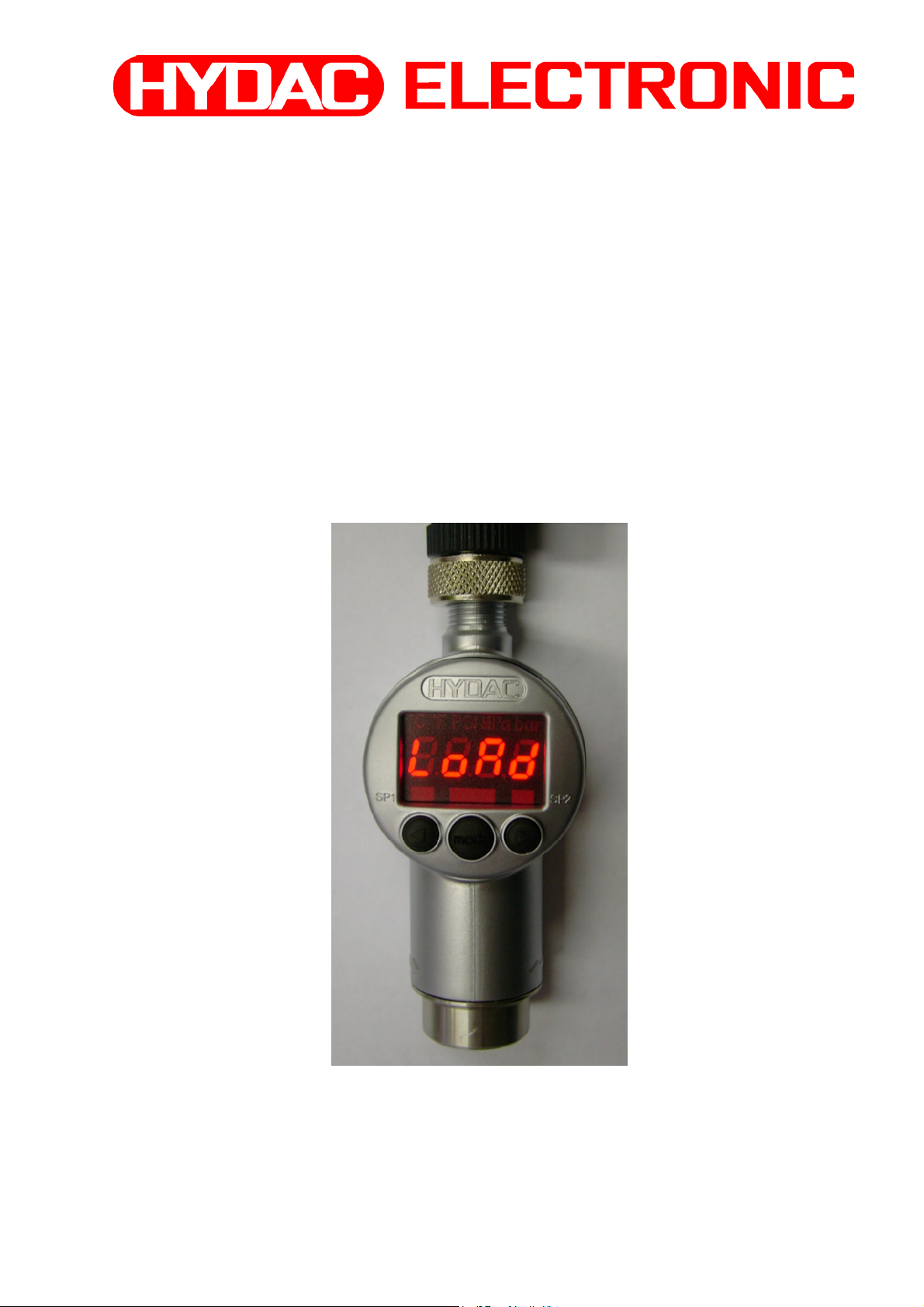
HYDAC Programmiergerät
HYDAC Programming unit
HYDAC Programmable
HPG 3000-000
Benutzerhandbuch / User manual / Notice d'utilisation
Mat. Nr.: 669716
Stand: 12.12.2008
Page 2

Benutzerhandbuch HYDAC Programmiergerät “HPG 3000-000“ 12.12.2008
INHALT
1. Funktionen des HPG 3000 3
2. Bedienelemente des HPG 3000 3
3. Anschluss EDS 4000 an HPG 3000 3
4. Druckschalterinformationen
4.1 Schaltpunkteinstellungen 4
4.1.1 Schaltpunkteinstellung 5
4.1.2 Hystereseeinstellung 5
4.1.3 Schaltrichtung 5
4.1.4 Einschaltverzögerung 6
4.1.5 Ausschaltverzögerung 6
4.2 Gerätespezifische Informationen 6
5. Fehlermeldungen 7
6. HPG 3000 Ablaufdiagramm 8
7. Anschlussbild 10
8. Technische Daten 10
9. Zubehör 10
10. Geräteabmessungen 11
1
Page 3

Benutzerhandbuch HYDAC Programmiergerät “HPG 3000-000“ 12.12.2008
Sicherheitshinweis:
Ist das HPG 3000 zwischen Druckschalter und Anlagen-Steuerung geschaltet, werden keine
Schaltfunktionen des Druckschalters vom HPG 3000 an die Anlagen-Steuerung
weitergereicht.
Das Programmieren des Druckschalters sowie das Auslesen und Anzeigen der
Druckschalterwerte und -einstellungen darf ausschließlich bei stillstehender Anlage
erfolgen!
Überprüfen Sie vor der Inbetriebnahme den ordnungsgemäßen
Zustand des Gerätes sowie des mitgelieferten Zubehörs.
Lesen Sie vor der Inbetriebnahme des Gerätes die Bedienanleitung
und stellen Sie sicher, dass das Gerät für Ihre Anwendung geeignet ist.
Falsche Handhabung bzw. die Nichteinhaltung von Gebrauchshinweisen
oder technischen Angaben kann zu Sach- und / oder Personenschäden führen.
Lieferumfang:
1x HPG 3000-000 HYDAC Programmiergerät
1x ZBE 30-02 Anschlusskabel, Länge 2m
1x Benutzerhandbuch
2
Page 4
Benutzerhandbuch HYDAC Programmiergerät “HPG 3000-000“ 12.12.2008
1. Funktionen des HPG 3000
• Einlesen der aktuellen Schaltpunkteinstellungen des Elektronischen Druckschalters EDS
4000*
• Ändern der Schaltpunkteinstellungen des EDS 4000* im HPG 3000
• Überspielen der geänderten Werte in den EDS 4000*
* EDS 4000 mit Programmiereingang
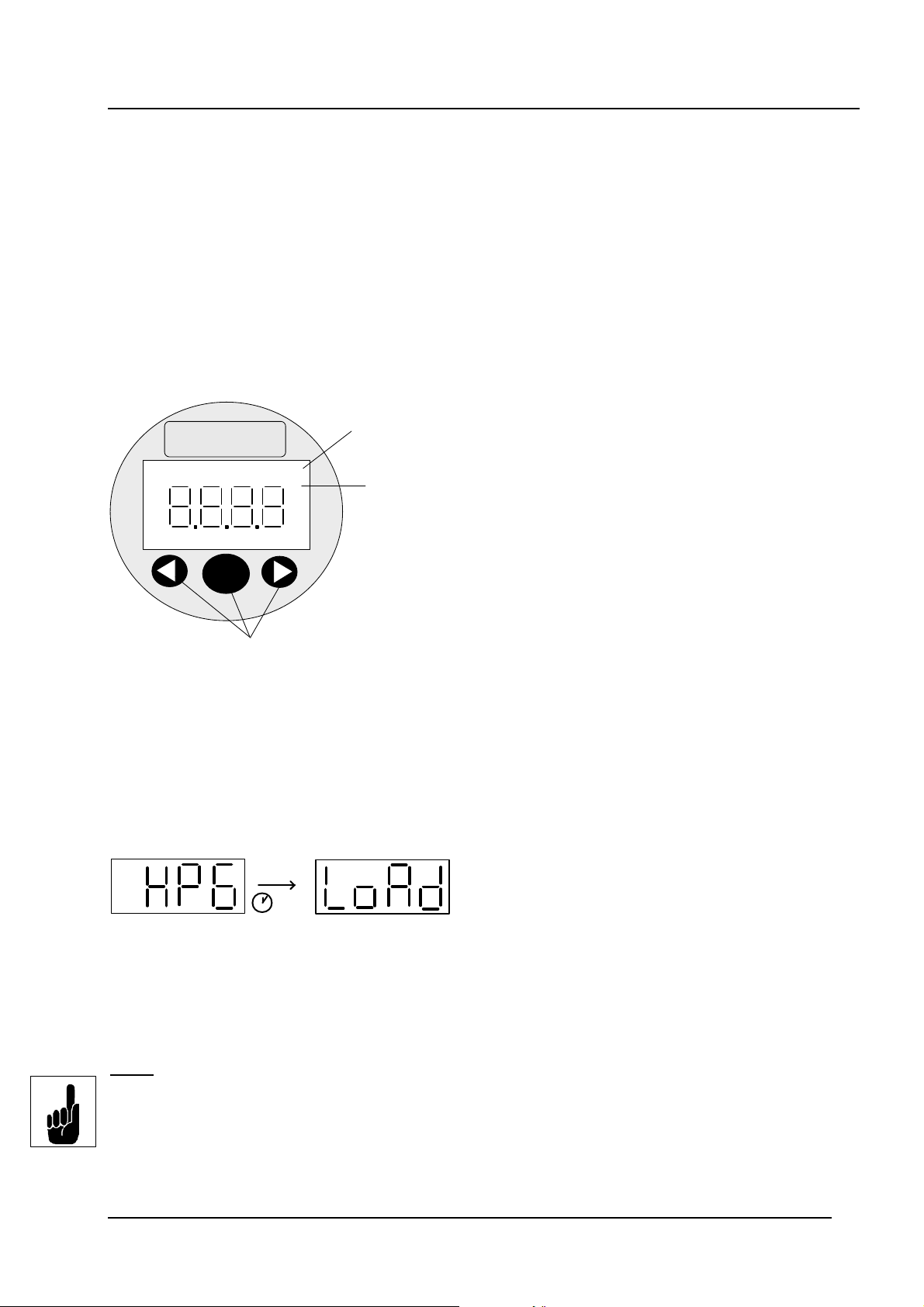
2. Bedienelemente des HPG 3000
Anzeige der
HYDAC
PSI bar
Druckeinheit
4-stellige
Digitalanzeige
SP1
ode
m
Tasten zur Einstellung der
Schaltpunkte, Rückschaltpunkte
und Zusatzfunktionen
SP2
3. Anschluss EDS 4000 an HPG 3000
Das HPG 3000 ist über das im Lieferumfang enthaltene Verbindungskabel ZBE 30-02 an
den EDS 4000 anzuschließen.
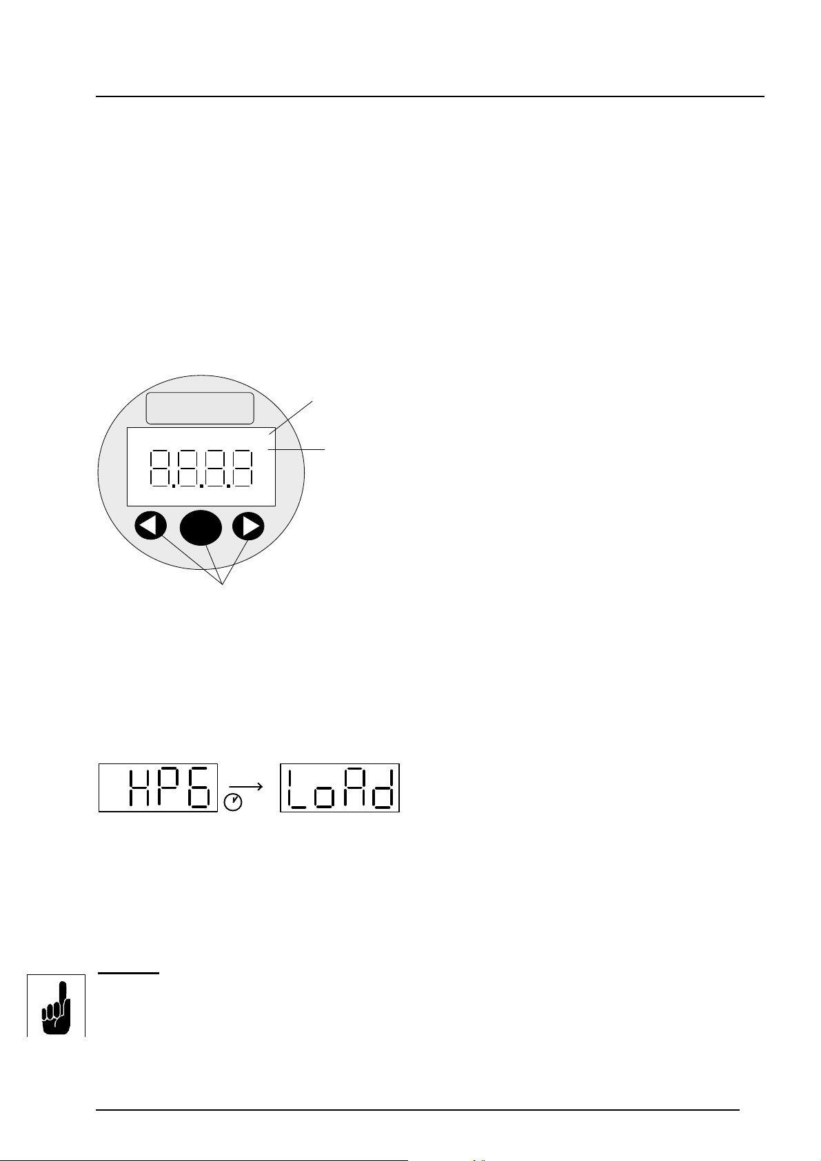
Nach dem Einschalten der Versorgungsspannung
zeigt das Gerät kurz “HPG” und anschließend
2 s
Durch das Betätigen der “mode“ – Taste werden die Daten des EDS 4000 an das
Programmiergerät übertragen. Dies wird durch die Meldung “rd“ (receive data) im Display
bestätigt.
“LoAd“ an.
Hinweis:
Ist kein EDS 4000 mit Programmiereingang angeschlossen, so wird beim Versuch der
Datenübertragung die Fehlermeldung “Er.21” angezeigt. Diese ist durch Drücken der
mode – Taste zu quittieren.
Er.21 = fehlende Verbindung oder Kommunikationsfehler
(z.B. EDS 4000 nicht angeschlossen)
3
Page 5
Benutzerhandbuch HYDAC Programmiergerät “HPG 3000-000“ 12.12.2008
4. Druckschalterinformationen
Mit dem HPG 3000 können die Schaltpunkteinstellungen des EDS 4000 eingelesen, geändert
und wieder in den EDS 4000 zurückgeschrieben werden. Da im Programmiergerät nach dem
Trennen der Versorgungsspannung keine Werte gespeichert werden können, müssen zuerst
nach jedem erfolgtem Zuschalten der Spannungsversorgung, die Daten des EDS 4000 in das
Programmiergerät eingelesen werden. Erst dann lassen sich die Schaltpunkteinstellungen
verändern, auch ohne Verbindung zum EDS 4000. Beim Auslesen werden auch Informationen
bzgl. der Druckeinheit übertragen (EDS 4000 eingestellt auf z. B. bar oder psi), sodass bei der
Änderung der Schaltpunkteinstellungen die Druckwerte direkt in der im EDS 4000
festeingestellten Druckeinheit geändert werden können. Dies ist am Aufleuchten der jeweiligen
Druckeinheit im Display zu erkennen.
Erst beim Überschreiben der Werte in den EDS 4000 bzw. erneuten Einlesen ins
Programmiergerät muss eine Verbindung zum EDS 4000 bestehen.
Ebenso werden beim Auslesen gerätespezifische Informationen ausgelesen.
Diese können im Info - Menü (inFo) überprüft werden.
Anhand der ausgelesenen Ziffer lässt sich erkennen, wie oft bereits der EDS 4000 in den
Einstellungen geändert wurde und ob nach letztmaligen Programmieren eine Änderung
vorgenommen wurde.
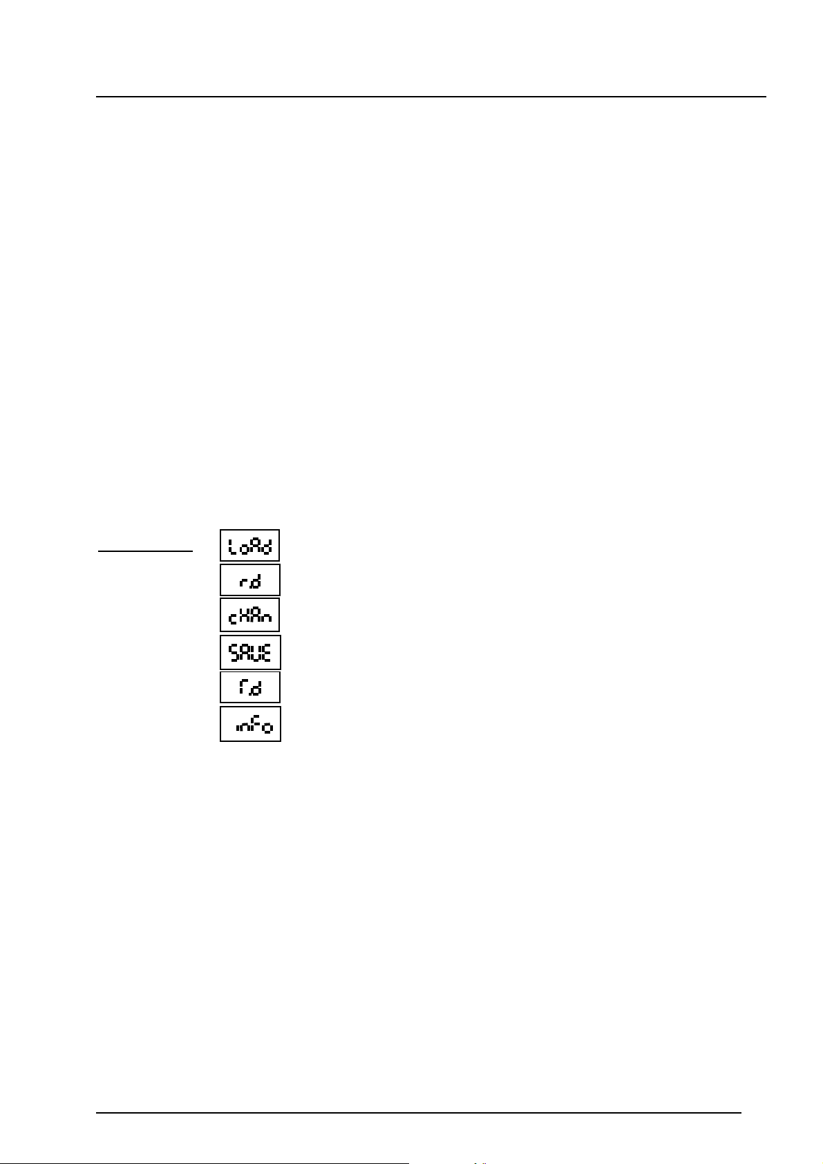
Abkürzungen:
= Einlesen der Werte in das Programmiergerät
= receive data (Daten werden ins HPG 3000 gelesen)
= Menü zum Ändern der Schaltpunkteinstellungen
= Überschreiben der Werte in den EDS 4000
= transfer data (Daten werden in den EDS 4000 übertragen)
= gerätespezifische Informationen
4.1 Schaltpunkteinstellungen
Im Menü zum Ändern der Schaltpunkteinstellungen “cHAn“ können folgende
Schaltpunkteinstellungen für den Schaltausgang 1 und Schaltausgang 2 verändert werden:
1. Schaltpunkteinstellung
2. Hystereseeinstellung
3. Schaltrichtung: Öffner- / Schließerfunktion
4. Einschaltverzögerung
5. Ausschaltverzögerung
4
Page 6
Benutzerhandbuch HYDAC Programmiergerät “HPG 3000-000“ 12.12.2008
4.1.1 Schaltpunkteinstellung
Es wird der Schaltpunkt eingestellt, bei dessen Überschreitung der Schaltausgang entsprechend
seiner voreingestellten Schaltrichtung (siehe 4.3) schaltet.
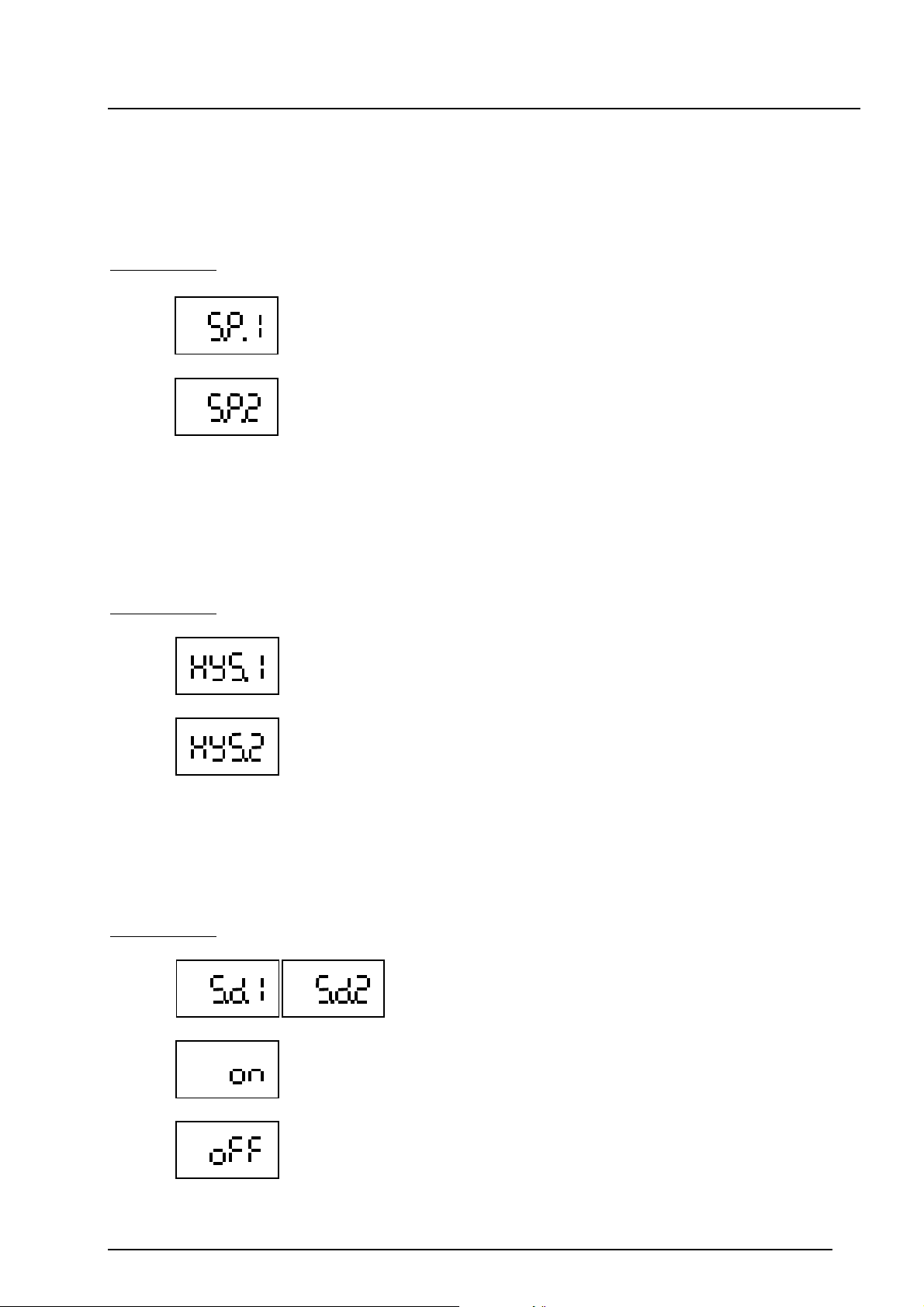
Abkürzungen:
= Schaltpunkt zu Schaltausgang 1
= Schaltpunkt zu Schaltausgang 2
4.1.2 Hystereseeinstellung
Zum Schaltausgang wird eine Hysterese eingestellt. Der Schaltausgang schaltet zurück wenn der
Rückschaltpunkt unterschritten wurde. Der Rückschaltpunkt wird durch die eingestellte Hysterese
bestimmt (Rückschaltpunkt = Schaltpunkt minus Hysterese).
Abkürzungen:
= Hysterese zu Schaltausgang 1
= Hysterese zu Schaltausgang 2
4.1.3 Schaltrichtung
Mit der Schaltrichtung wird festgelegt, ob die Schaltfunktion des Schaltausgangs als Schließeroder Öffnerkontakt arbeitet.
Abkürzungen:
= Schaltrichtung
= Schließerkontakt
= Öffnerkontakt
5
Page 7
Benutzerhandbuch HYDAC Programmiergerät “HPG 3000-000“ 12.12.2008
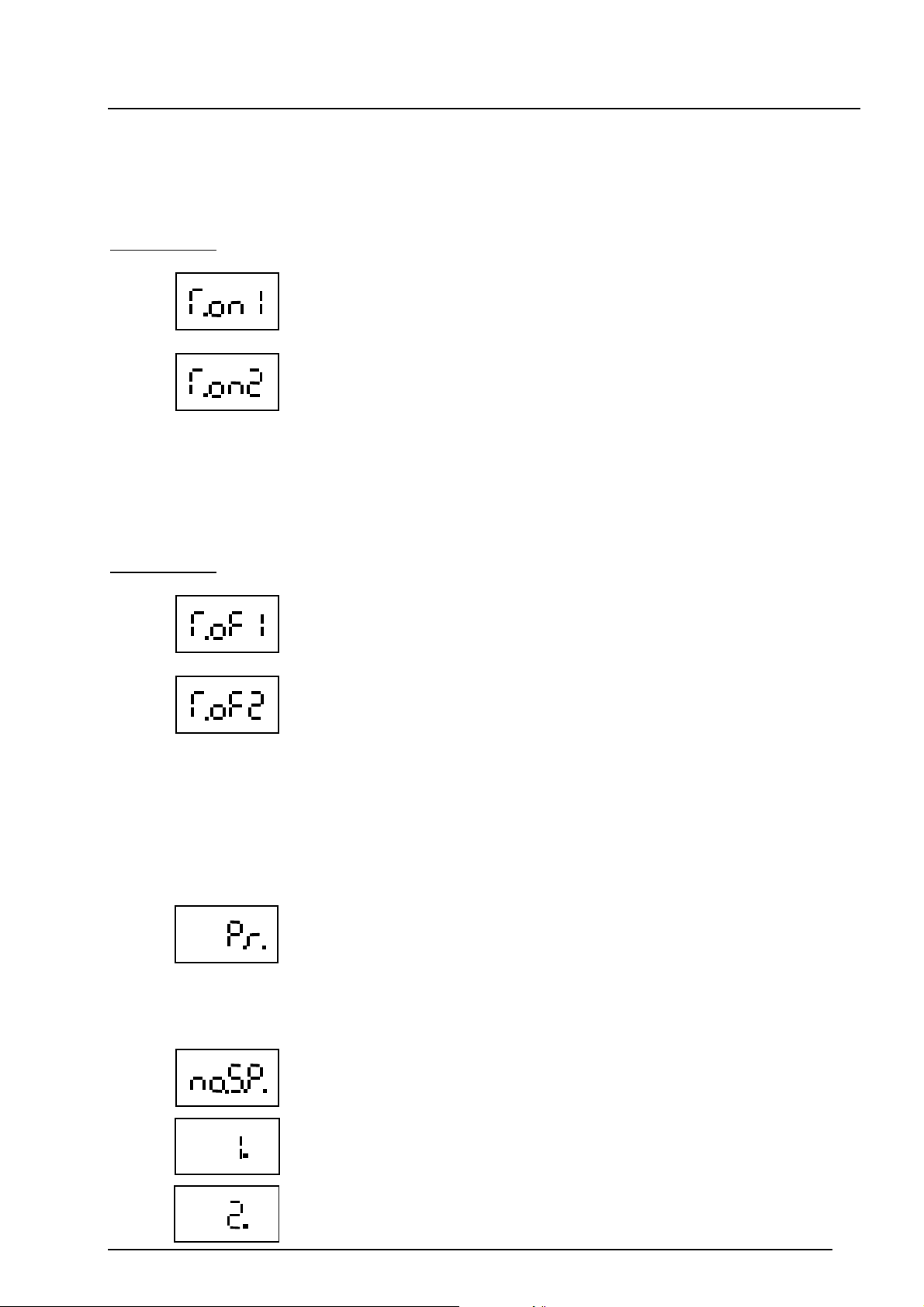
4.1.4 Einschaltverzögerung
Die Einschaltverzögerung ist ein Wert in Millisekunden [ms] der angibt, über welche Zeitdauer der
Schaltwert erreicht bzw. überschritten sein muss, damit ein Schaltvorgang erfolgt.
Abkürzungen:
= Einschaltverzögerung [ms] für Schaltausgang 1
= Einschaltverzögerung [ms] für Schaltausgang 2
4.1.5 Ausschaltverzögerung
Die Ausschaltverzögerung ist ein Wert in Millisekunden [ms] der angibt, über welche Zeitdauer
der Rückschaltpunkt unterschritten sein muss, damit ein Schaltvorgang erfolgt.
Abkürzungen:
= Ausschaltverzögerung [ms] für Schaltausgang 1
= Ausschaltverzögerung [ms] für Schaltausgang 2
4.2 Gerätspezifische Informationen
Im Info-Menü können gerätespezifische Informationen schnell und einfach überprüft werden.
Dabei werden folgende Angaben dargestellt:
- Messbereich (Pressure range)
= Anzeige des Messbereichs des angeschlossenen EDS 4000
- Anzahl der Schaltausgänge
= Anzahl der Schaltausgänge des angeschlossenen EDS 4000
(number of Switch points)
= Der angeschlossene EDS 4000 bietet 1 Schaltausgang
= Der angeschlossene EDS 4000 bietet 2 Schaltausgänge
6
Page 8
Benutzerhandbuch HYDAC Programmiergerät “HPG 3000-000“ 12.12.2008
= Der angeschlossene EDS 4000 bietet 2 Schaltausgänge.
SP1,HYS1, T.on1 und T.of1 zu Schaltausgang 1 sind einstellbar,
die Werte werden für SP2, HYS2, T.on2 und T.of2 für
Schaltausgang 2 übernommen .
Die Signalausgabe an den Schaltausgängen erfolgt antivalent
(gegengleichschaltend)
= Der angeschlossene EDS 4000 bietet 2 Schaltausgänge.
SP1,HYS1, T.on1 und T.of1 zu Schaltausgang 1 sind einstellbar,
die Werte werden für SP2, HYS2, T.on2 und T.of2 für
Schaltausgang 2 übernommen .
Die Signalausgabe an den Schaltausgängen erfolgt valent
(gleichschaltend)
- Ereigniszähler
= Ereigniszähler (change Event counter)
Dieser Zähler wird beim Überschreiben geänderter Schaltpunkt einstellungen in den EDS 4000 um Eins erhöht.
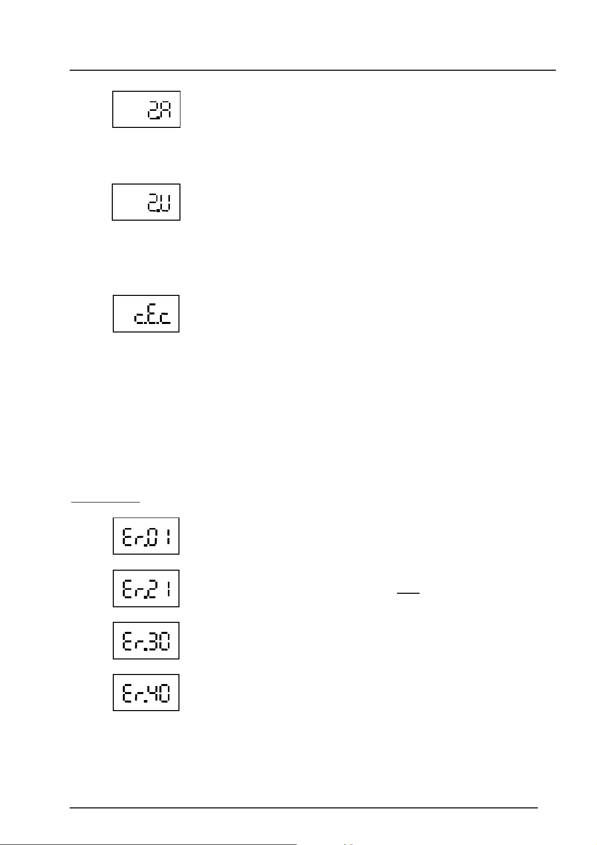
5. Fehlermeldungen
Sind die Schaltpunkt- und Hystereseeinstellungen so getätigt, dass der resultierende Rückschaltpunkt nicht mehr im erlaubten Einstellbereich liegt, so wird die Fehlermeldung “Er.01”
angezeigt. Die Einstellungen für den Schaltpunkt und die Hysterese sind zu korrigieren.
Ist kein EDS 4000 mit Programmiereingang angeschlossen, so wird beim Versuch der
Datenübertragung die Fehlermeldung “Er.21” angezeigt. Diese Meldung ist ein Hinweis auf eine
fehlerhafte Datenkommunikation und ist durch Drücken der mode – Taste zu quittieren.
Abkürzungen:
= Falsche Schaltpunkt- / Hystereseeinstellung
= Fehlende Verbindung zum EDS 4000 oder
= Für den angeschlossenen EDS 4000 wurde keine sinnvolle Anzahl
von Schaltausgängen ausgelesen.
Kommunikationsfehler
= Der angeschlossene EDS 4000 verfügt über eine Window-Funktion.
(Ein EDS 4000 mit dieser Modifikation kann mit dem HPG 3000 nicht
programmiert werden.)
7
Page 9
Benutzerhandbuch HYDAC Programmiergerät “HPG 3000-000“ 12.12.2008
m
ode
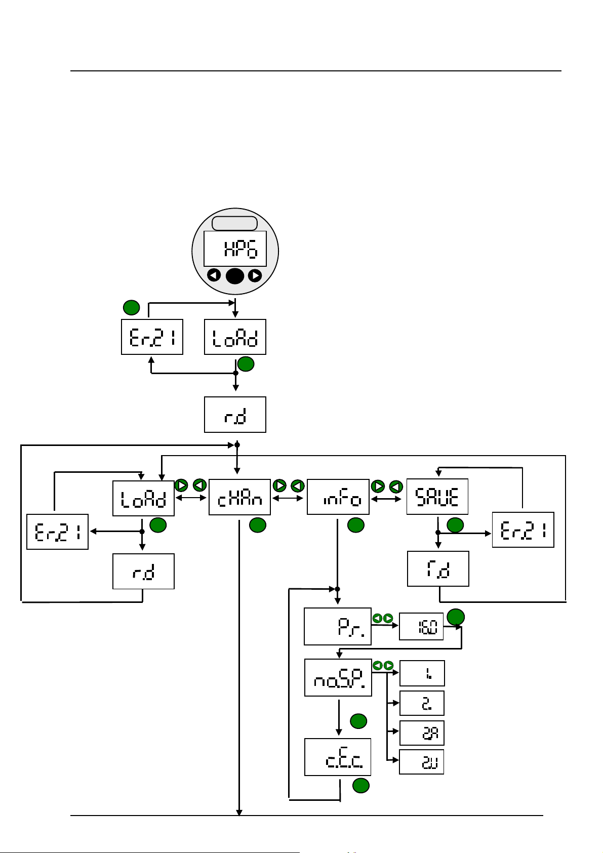
6. HPG 3000 - Ablaufdiagramm
Nach dem Verbinden des HPG 3000 mit dem EDS 4000 ist die Spannungsversorgung
uzuschalten.
z
Danach kann wie dargestellt durch die entsprechenden Menüs navigiert werden.
Hinweis: Wird während 5 s keine Taste betätigt, so springt die Anzeige in das übergeordnete
Menü. Dabei werden geänderte Werte übernommen.
HYDAC
mode
mod e
mod e
mod e
mod e
mod e
mod e
8
Page 10
Benutzerhandbuch HYDAC Programmiergerät “HPG 3000-000“ 12.12.2008
mode
mode
mode
mode
mode
mode
mode
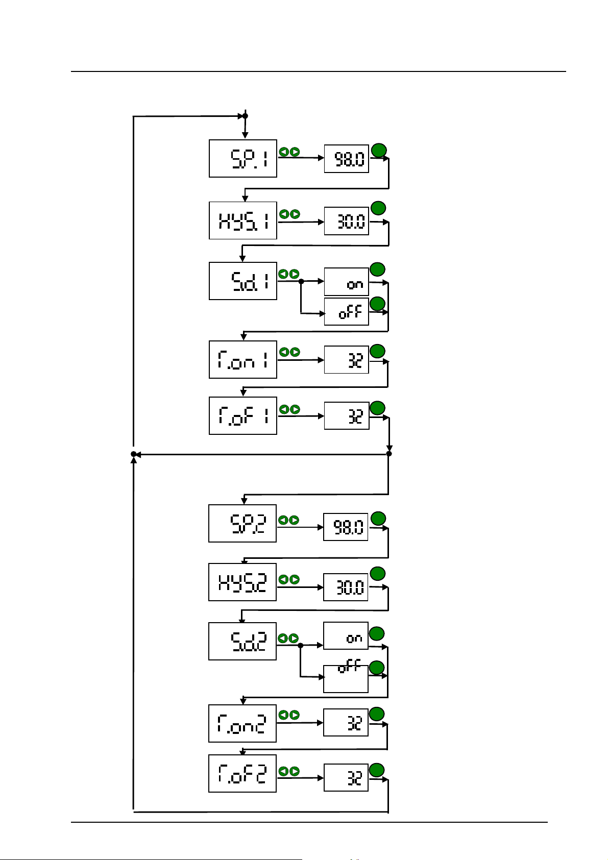
EDS 4000 mit 2 unabhängigen Schaltausgängen
mode
mode
mode
mode
mode
9
Page 11
Benutzerhandbuch HYDAC Programmiergerät “HPG 3000-000“ 12.12.2008
Anzeige (Taste
Hinweis:
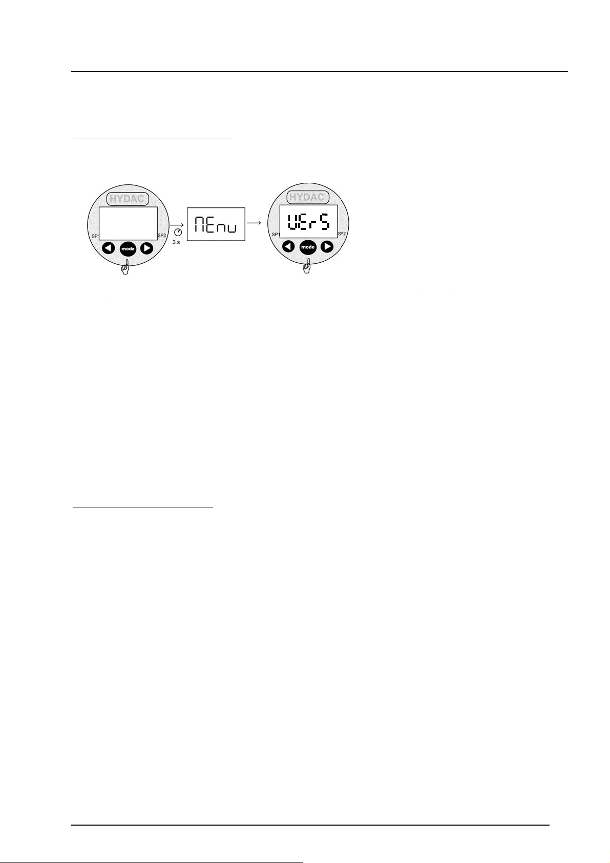
Im Basismenü des HPG 3000 ist die Versionsnummer des vorliegenden Programmiergerätes
hinterlegt.
Anzeigen der Versionsnummer:
Taste mode
betätigen und
festhalten.
Versorgungsspannung
einschalten
(Taste so lange
betätigt lassen,
bis in der
Anzeige die
Meldung "Menü"
Verlassen des Basismenüs:
Mit der Taste mode den Menüpunkt „END“ anwählen, durch Drücken der Tasten oder „Yes“
auswählen und mit mode bestätigen.
„mode“
loslassen)
In der Anzeige
erscheint die
Versionsnummer
des HPG 3000.
10
Page 12
Benutzerhandbuch HYDAC Programmiergerät “HPG 3000-000“ 12.12.2008
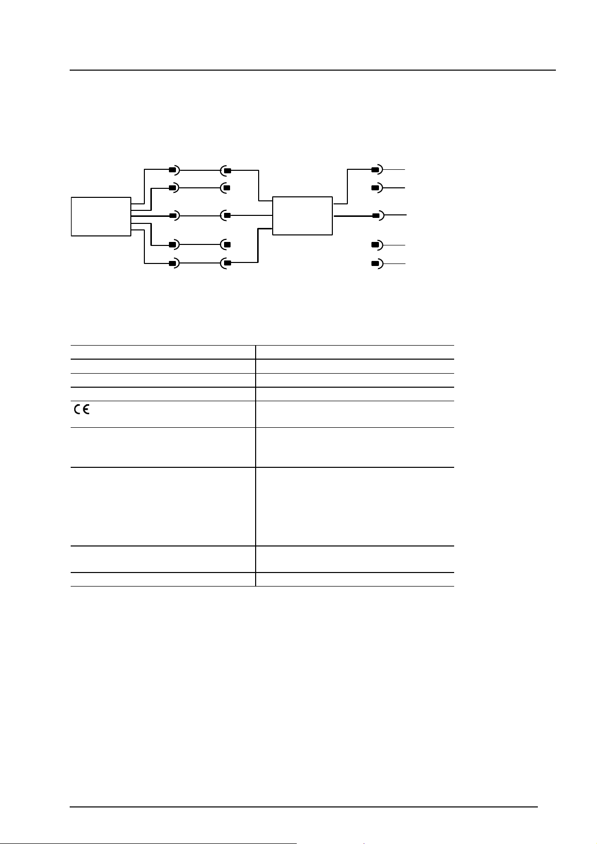
7. Anschlussbild
nschluss des programmierbaren Druckschalters EDS 4000 an das HYDAC Programmiergerät
A
HPG 3000:
1
+Ub
+Ub
1
1
EDS 4000
2
3
4
5
0 V
Comport
2
3
4
5
HPG 3000
2
0 V
3
4
5
8. Technische Daten
Versorgungsspannung: 12 .. 35 V
Stromaufnahme:
35 mA
Umgebungstemperaturbereich: -25 .. + 80 °C
Lagertemperaturbereich: -40 .. + 80 °C
-Zeichen: EN 61000-6-1, EN 61000-6-2,
EN 61000-6-3, EN 61000-6-4
Anschluss Spannungsversorgung: Gerätestecker M12x1, 4-polig
Pin 1: +U
Pin 3: 0 V
Anschluss Programmierausgang: Gerätebuchse M12x1, 5-polig
Pin 1: +U
Pin 2: nicht angeschlossen
Pin 3: 0 V
Pin 4: nicht angeschlossen
Pin 5: CP
Anzeige: 4-stellig, LED, 7-Segment, rot,
Zeichenhöhe 7 mm
Gewicht: ca. 120 g
C
D
B
B
9. Zubehör
ZBE 30-02 Anschlusskabel M12x1, Länge 2m (Best.-Nr.: 6040851)
ZBE 30-05 Anschlusskabel M12x1, Länge 5m (Best.-Nr.: 6040852)
11
Page 13
Benutzerhandbuch HYDAC Programmiergerät “HPG 3000-000“ 12.12.2008
5
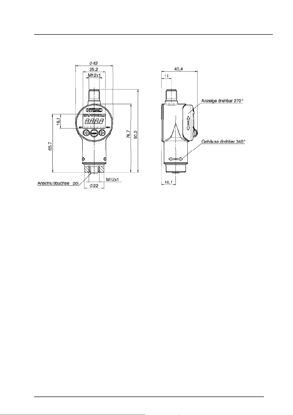
10. Geräteabmessungen
HYDAC ELECTRONIC GMBH
Hauptstr. 27
D-66128 Saarbrücken
Germany
Tel.: +49-(0)6897-509-01
Fax: +49-(0)6897-509-1726
HYDAC Service
Für Fragen zu Reparaturen steht Ihnen der HYDAC Service zur Verfügung.
HYDAC SERVICE GMBH
Hauptstr. 27
D-66128 Saarbrücken
Germany
Tel.: +49-(0)6897-509-1936
Fax: +49-(0)6897-509-1933
Anmerkung
Die Angaben in dieser Bedienungsanleitung beziehen sich auf die beschriebenen
Betriebsbedingungen und Einsatzfälle. Bei abweichenden Einsatzfällen und/oder
Betriebsbedingungen wenden Sie sich bitte an die entsprechende Fachabteilung.
Bei technischen Fragen, Hinweisen oder Störungen nehmen Sie bitte Kontakt mit Ihrer
HYDAC-Vertretung auf.
Technische Änderungen sind vorbehalten.
12
Page 14

User Manual HYDAC Programming Unit “HPG 3000-000“ 2008/12/12
Contents
1. Functions of the HPG 3000 3
2. Operating keys of the HPG 3000 3
3. Connecting the EDS 4000 to the HPG 3000 3
4. Pressure switch information
4.1 Switch point settings 4
4.1.1 Switch point 5
4.1.2 Hysteresis 5
4.1.3 Switching direction 5
4.1.4 Switch on delay 6
4.1.5 Switch off delay 6
4.2 Information specific to the unit 6
5. Error messages 7
6. HPG 3000 menu flow chart 8
7. Connection diagram 10
8. Technical data 10
9. Accessories 10
10. Dimensions 11
1
Page 15

User Manual HYDAC Programming Unit “HPG 3000-000“ 2008/12/12
Safety advice:
If the HPG 3000 is installed between a pressure switch and the control system, then the
switching functions of the pressure switch will not be transmitted to the control system.
Programming of the pressure switch as well as reading out and displaying values and
setting up of the parameters within the pressure switch, may only be carried out with the
control system switched off.
Before putting the switch into service, please check that the switch and the accessories supplied
have no apparent defects. Please read the Manual before installing the switch and ensure that it
is suitable for your application.
If the unit is not handled correctly, or if the operating instructions and specifications are not
adhered to, damage to the product or to personal injury may result.
Items supplied:
1x HPG 3000-000 HYDAC Programming Unit
1x ZBE 30-02 Connection cable, length 2m
1x User Manual
2
Page 16
User Manual HYDAC Programming Unit “HPG 3000-000“ 2008/12/12
1. Functions of the HPG 3000
• For uploading actual switch point settings from the electronic pressure switch EDS 4000*
• For altering the switch point settings of the EDS 4000* in the HPG 3000
• For transferring the altered data back into the EDS 4000*
* EDS 4000 with programming input
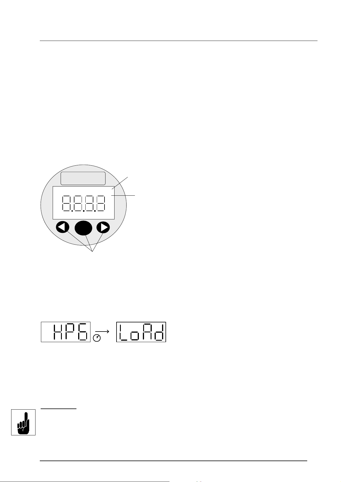
2. Operating keys of the HPG 3000
Display of the
Anzeige der
pressure unit of
Druckeinheit
HYDAC
PSI bar
measurement
4 digit
-stellige
4
digital display
Digitalanzeige
SP1
mode
Keys for adjusting switching output
Tasten zur Einstellung der
settings and for scrolling through the menu
Schaltpunkte, Rückschaltpunkte
und Zusatzfunktionen
SP2
3. Connecting the EDS 4000 to the HPG 3000
Use the connection cable ZBE 30-02 which is supplied with the unit to connect the HPG 3000 to
the EDS 4000.
After switching on the supply voltage the message
“HPG” appears in the display for about 2 seconds,
2 s
When the “mode“ key is pressed, the data from the EDS 4000 is transferred to the programming
unit.
This is confirmed by the message “rd“ (receive data) in the display.
followed by “LoAd”.
Note:
If no EDS 4000 with programming input is connected, the error message “Er.21” will appear in
the display when you try to transfer data. This message must to be acknowledged by pressing
the mode key.
Er.21 = missing connection or communication fault (e.g. EDS 4000 not connected)
3
Page 17
User Manual HYDAC Programming Unit “HPG 3000-000“ 2008/12/12
4. Pressure switch information
The HPG 3000 can be used to upload and change the switch point settings of the EDS 4000 and
then transfer them back into an EDS 4000. As no values can be stored in the programming unit
after disconnecting the supply voltage, the data on the EDS 4000 must first be uploaded into the
programming unit each time the supply voltage is switched on. Only then can the switch point
settings be changed (does not need to be connected to the EDS 4000 to make changes). During
transfer, information regarding the pressure unit is also transferred (EDS 4000 is set to either bar
or psi, as supplied), so that when changing the switch point settings, the pressure values can be
changed immediately into the designated unit of measurement in the EDS 4000. The relevant unit
of measurement is lit up in the display.
The EDS 4000 only needs to be connected when the values are being overwritten in the
EDS 4000 or when the values are uploaded again into the programming unit.
In the same way, unit-specific information is also transferred during the transfer process.
The information can be checked in the info menu (inFo).
It can be seen from the transferred figures how often the EDS 4000 settings have already been
changed and whether a change has taken place since the last programming.
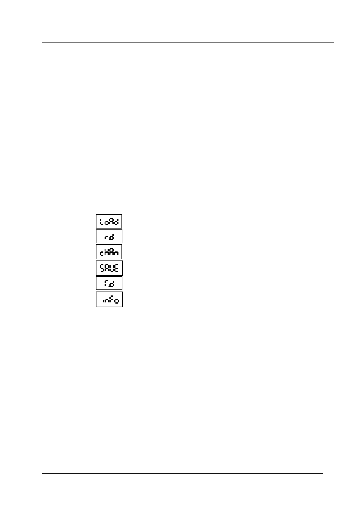
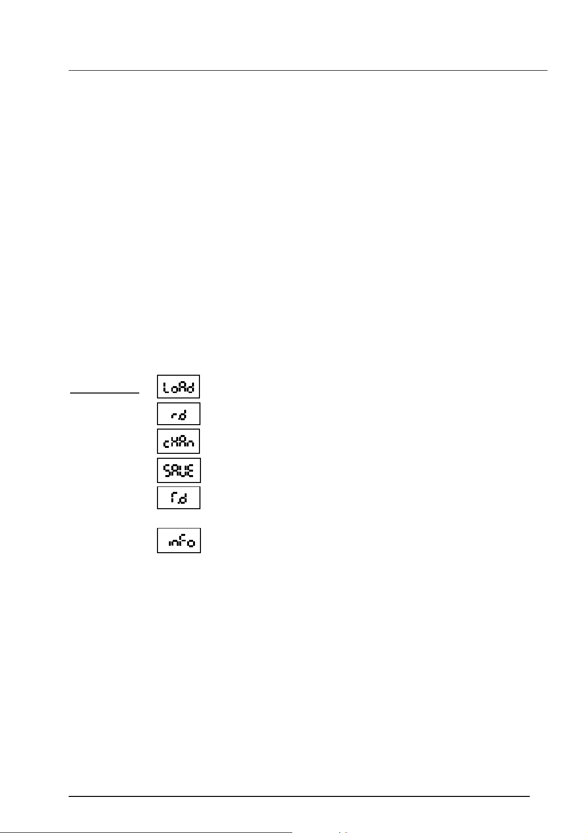
Abbreviations:
= uploading the values into the programming unit
= receive data (data is transferred to the HPG 3000)
= menu for changing the switch point settings
= overwrite the values in the EDS 4000
= transfer data (data is transferred to the EDS 4000)
= information specific to the unit
4.1 Switch point settings
In the change menu (“cHAn“), the following switch point settings can be changed for switching
output 1 and switching output 2:
1. Switch point setting
2. Hysteresis setting
3. Switching direction: N/C or N/O function
4. Switch on delay
5. Switch off delay
4
Page 18
User Manual HYDAC Programming Unit “HPG 3000-000“ 2008/12/12
4.1.1 Switch point setting
This sets the switch point at which the switching output will switch according to its N/O or N/C
direction (see 4.3) when the value goes above or below this point.
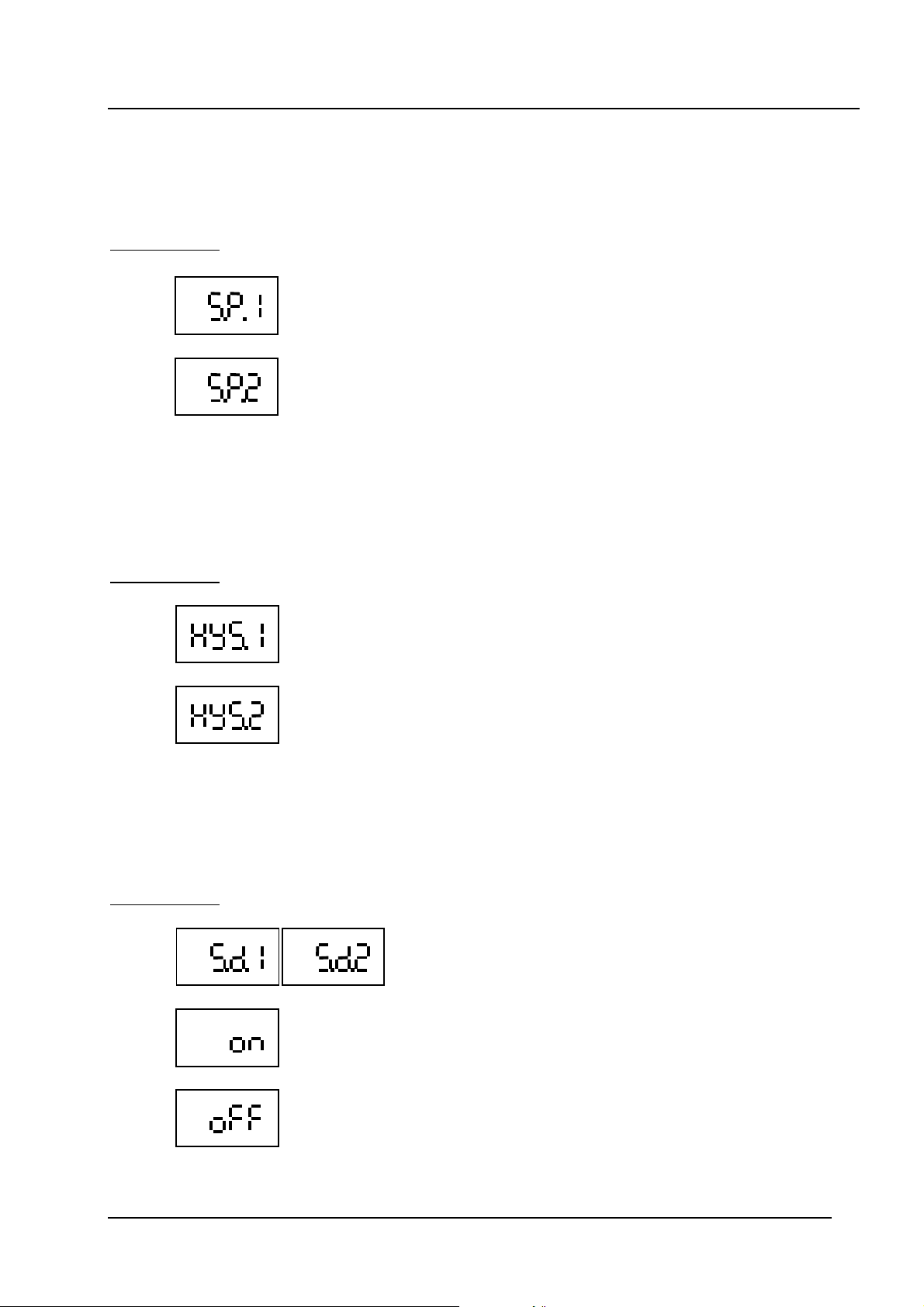
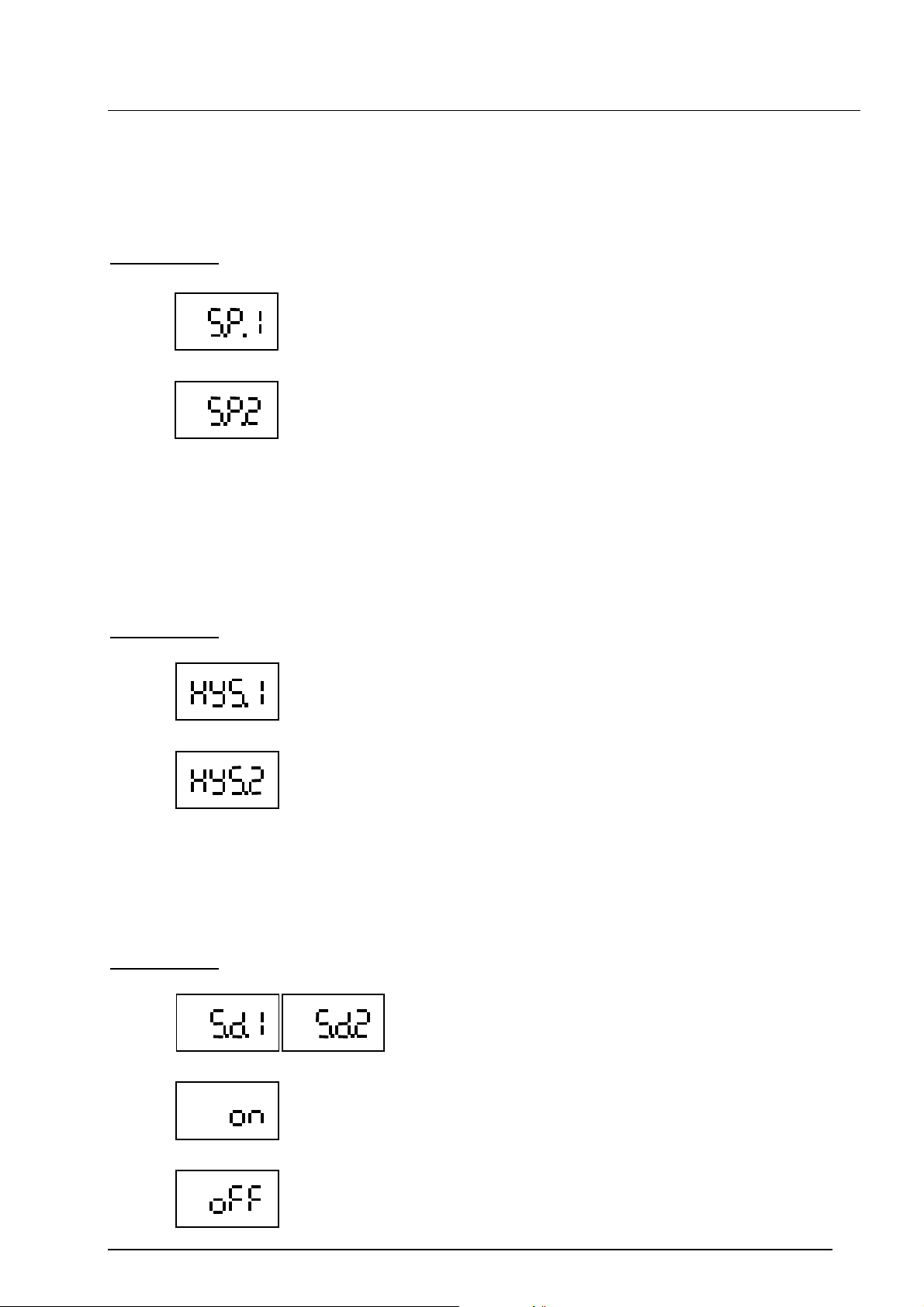
Abbreviations:
= Switch point for switching output 1
= Switch point for switching output 2
4.1.2 Hysteresis setting
This sets a hysteresis for the switch point. The switching output switches back if the value falls
below the switch-back point. The switch-back point is determined by the hysteresis (switch-back
point = switch point minus hysteresis).
Abbreviations:
= Hysteresis for switching output 1
= Hysteresis for switching output 2
4.1.3 Switching direction
The switching direction determines if the switching function is to be normally open or normally
closed.
Abbreviations:
= Switching direction for switching output 1 or 2
= Normally open function
= Normally closed function
5
Page 19
User Manual HYDAC Programming Unit “HPG 3000-000“ 2008/12/12
4.1.4 Switch on delay
Time in milliseconds [ms] which must elapse, once the switch point has been reached or
exceeded, before switching will occur.
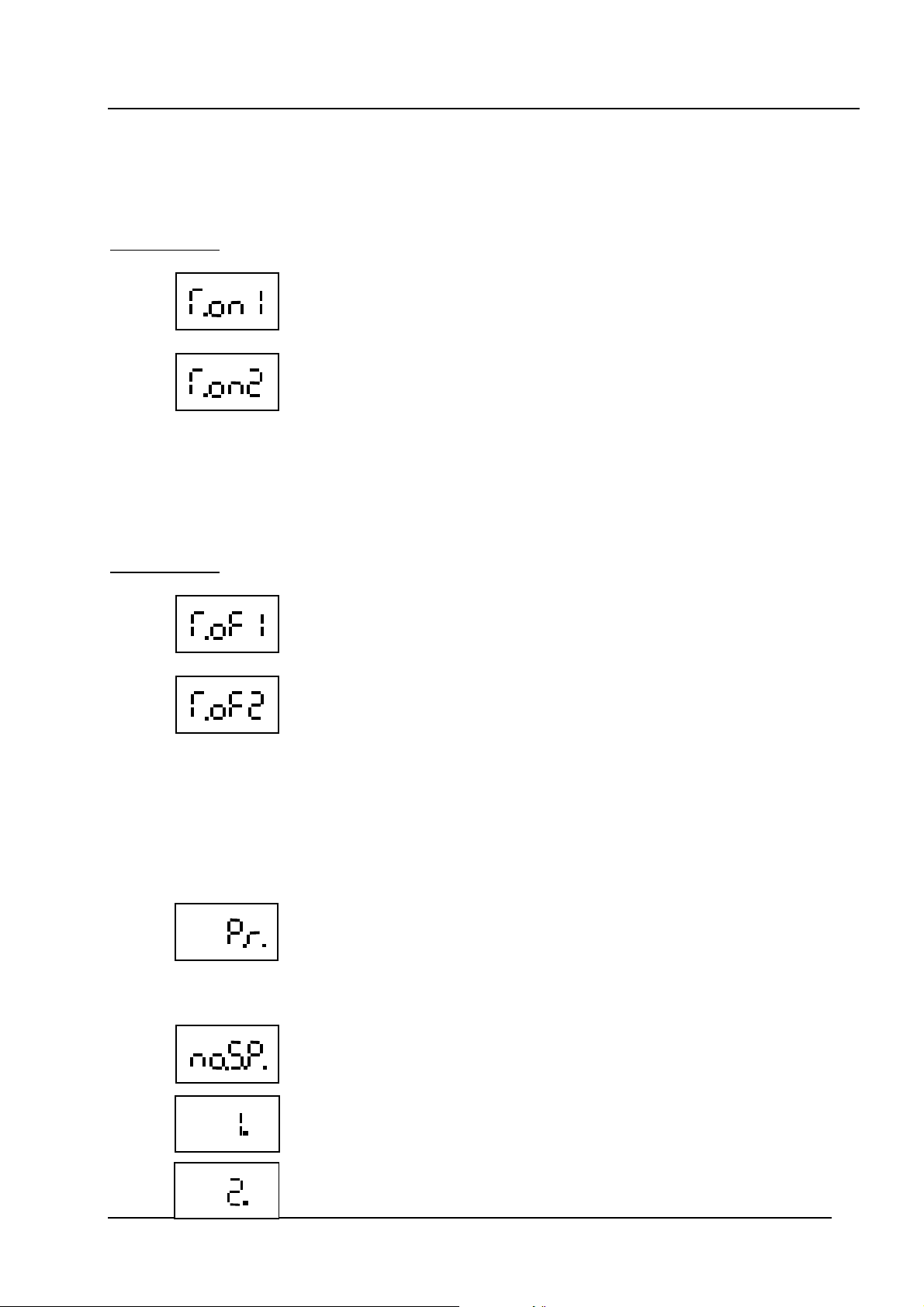
Abbreviations:
= Switch on delay [ms] for switching output 1
= Switch on delay [ms] for switching output 2
4.1.5 Switch off delay
Time in milliseconds which must elapse, once the pressure has fallen below the particular switchback point, before switching will occur.
Abbreviations:
= Switch off delay [ms] for switching output 1
= Switch off delay [ms] for switching output 2
4.2 Information specific to the unit
In the info menu, information specific to the unit can be checked quickly and simply.
The following details are displayed:
- Measuring range (Pressure range)
= display of the measuring range of the EDS 4000 connected
- Number of switch outputs
= Number of switch outputs of the EDS 4000 connected
(number of switch points)
= The connected EDS 4000 has 1 switch output
= The connected EDS 4000 has 2 switch outputs
6
Page 20
User Manual HYDAC Programming Unit “HPG 3000-000“ 2008/12/12
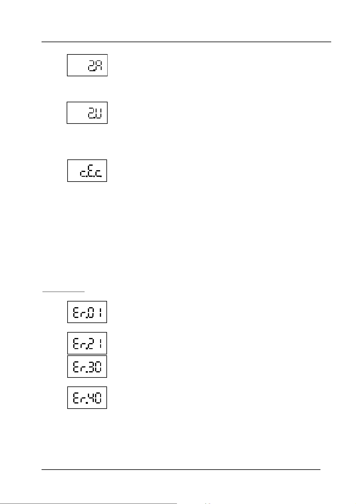
= The connected EDS 4000 has 2 switch outputs available.
SP1, HYS1, T.on1 and T.of1 for switch output 1 are adjustable.
The values are transferred for SP2, HYS2, T.on2 and T.of2 for
switch output 2. The switch outputs are antivalent
(switching simultaneously in opposite directions)
= The connected EDS 4000 has 2 switch outputs available.
SP1, HYS1, T.on1 and T.of1 for switch output 1 are adjustable.
The values are transferred for SP2, HYS2, T.on2 and T.of2 for
switch output 2. The switch outputs are valent
(switching simultaneously in the same direction)
- Change event counter
= change event counter
This counter increases by one every time changed switch point
settings are overwritten in the EDS 4000.
5. Error messages
If the switch point settings and the hysteresis settings are set so that the resulting switch back
point is no longer in the permitted setting range, then the error message “Er.01” appears in the
display.
The settings for the switch point and the hysteresis must be corrected.
If no EDS 4000 with programmable input is connected when attempting data transfer, the error
message “Er.21” appears in the display. This message indicates a faulty data communication and
must be acknowledged pressing the mode key.
Abbreviations:
= incorrect switch point / hysteresis setting
= no connection to EDS 4000 or communication fault
= for the EDS 4000 connected, the quantity of switch outputs read out
was not meaningful.
= the EDS 4000 connected has a Window function.
(An EDS 4000 with this modification cannot be programmed using
the HPG 3000.)
7
Page 21
User Manual HYDAC Programming Unit “HPG 3000-000“ 2008/12/12
mod e
m
ode
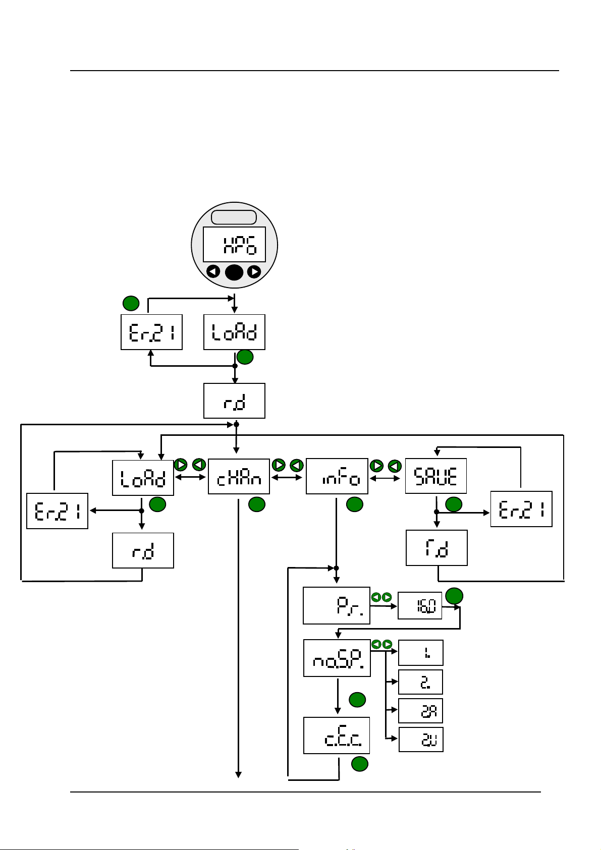
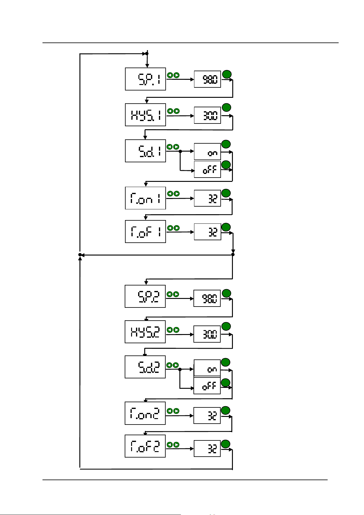
6. HPG 3000 – program flow chart
After connecting the HPG 3000 to the EDS 4000, switch on the voltage supply.
The message “HPG“ appears.
Afterwards you can navigate through the relevant menus, as shown.
Note: If no key is pressed for 5 s, the display jumps to the next higher menu. In so doing
changed values are accepted.
HYDAC
mode
mod e
mod e
mod e
mod e
mod e
8
Page 22
User Manual HYDAC Programming Unit “HPG 3000-000“ 2008/12/12
mode
mode
mode
mode
mode
mode
for EDS 4000 with 2 independent switching outputs
mode
mode
mode
mode
mode
mode
9
Page 23
User Manual HYDAC Programming Unit “HPG 3000-000“ 2008/12/12
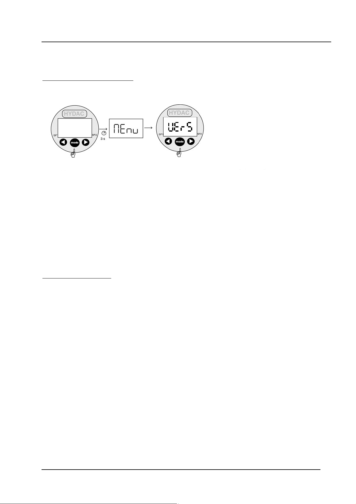
Note:
The version number of the present programming unit is stored in the basic menu of the HPG
3000.
To display the version number:
Press and hold
down the mode
button. Turn on
the supply voltage
(hold down the
button until the
message "menu"
appears)
To exit the basic menu:
Using the mode button, select menu point "END", select "Yes" by pressing arrow keys or
and confirm with mode.
Display
(release
"mode" button)
The version
number of the
HPG 3000 is
displayed.
10
Page 24
User Manual HYDAC Programming Unit “HPG 3000-000“ 2008/12/12
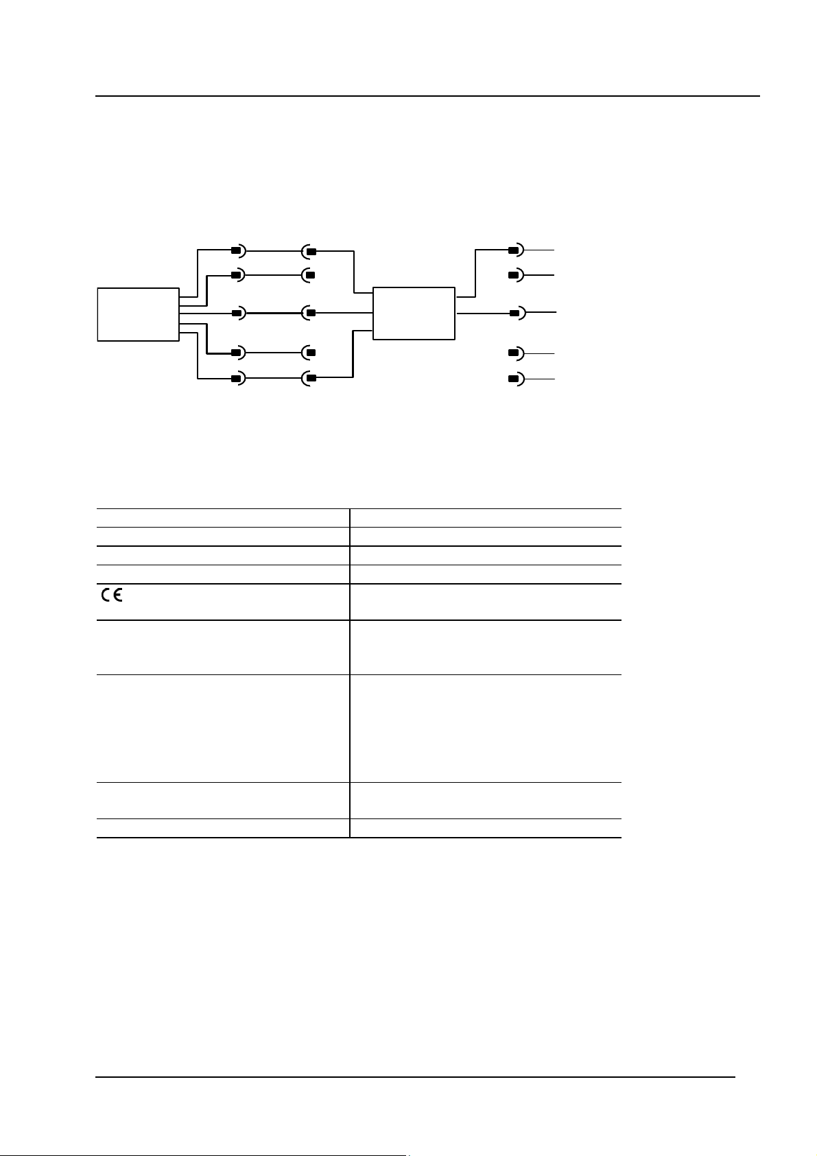
7. Connection diagram
onnecting the programmable pressure switch EDS 4000 to the HYDAC Programming Unit
C
HPG 3000:
+
1
Ub
1
+Ub
1
EDS 4000
2
3
4
5
0 V
Comport
2
3
4
5
HPG 3000
2
0 V
3
4
5
8. Technical data
Supply voltage: 12 .. 35 V
Current consumption: 35 mA
Ambient temperature range: -25 .. + 80 °C
Storage temperature range: -40 .. + 80 °C
mark: EN 61000-6-1, EN 61000-6-2,
EN 61000-6-3, EN 61000-6-4
Connection of voltage supply: Male connector M12x1, 4-pole
Pin 1: +U
Pin 3: 0 V
Connection of programming output:
female connector M12x1, 5-pole
Pin 1: +U
Pin 2: not connected
Pin 3: 0 V
Pin 4: not connected
Pin 5: CP
Display: 4-digit, LED, 7-segment, red,
height: 7 mm
Weight: approx. 120 g
B
B
DC
9. Accessories
ZBE 30-02 cable with M12x1 connectors, length 2m (part no.: 6040851)
ZBE 30-05 cable with M12x1 connectors, length 5m (part no.: 6040852)
11
Page 25
User Manual HYDAC Programming Unit “HPG 3000-000“ 2008/12/12
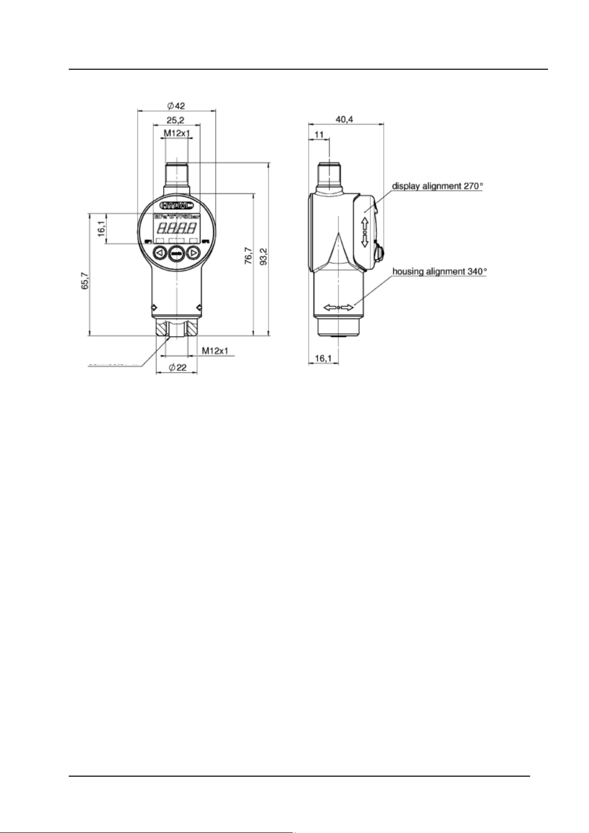
10. Dimensions
connector 5P
HYDAC ELECTRONIC GMBH
Hauptstr. 27
D-66128 Saarbrücken
Germany
Tel.: +49-(0)6897-509-01
Fax: +49-(0)6897-509-1726
HYDAC Service
If you have any questions concerning repair work, please do not hesitate to contact HYDAC
Service:
HYDAC SERVICE GMBH
Hauptstr. 27
D-66128 Saarbrücken
Germany
Tel.: +49-(0)6897-509-1936
Fax: +49-(0)6897-509-1933
Note
The information in this brochure relates to the operating conditions and applications described.
For applications or operating conditions not described, please contact the relevant technical
department.
If you have any queries, suggestions, or encounter any problems of a technical nature, please
contact your HYDAC representative.
Subject to technical modifications.
12
Page 26

Notice de programmation HYDAC de “HPG 3000-000“ 12.12.2008
SOMMAIRE
1. Fonction de l‘ HPG 3000 3
2. Eléments de la face avant de l‘ HPG 3000 3
3. Branchement de l‘ EDS 4000 sur HPG 3000 3
4. Configurations
4.1 Réglage du seuil de commutation 4
4.1.1 Réglage du seuil de commutation 5
4.1.2 Réglage de l’hystérésis 5
4.1.3 Sens de commutation 5
4.1.4 Temporisation à l’enclenchement 6
4.1.5 Temporisation au déclenchement 6
4.2 Réglage spécifiques 6
5. Messages d’erreurs 7
6. HPG 3000 Diagramme de fonctionnement 8
7. Schéma de branchement 10
8. Données techniques 10
9. Accessoires 10
10. Dimensions de l’appareil 11
1
Page 27

Notice de programmation HYDAC de “HPG 3000-000“ 12.12.2008
Consignes de sécurité:
Si l'HPG 3000 est commuté entre le manomètre et le pilotage de la centrale, aucune
fonction de commutation du manomètre ne sera transférée au pilotage de la
centrale.
La programmation du manomètre ainsi que la lecture et l'affichage des valeurs de
l'appareil ne doivent s'effectuer que sur une centrale à l'arrêt.
Veillez à ce que la mise en service soit effectuée dans les règles par un professionnel.
Veillez également le bon état des appareils et accessoires livrés.
Avant la mise en service des appareils, il faut lire le mode d’emploi et assurez vous que
l’usage de l’appareil est approprié à votre application.
Une mauvaise manipulation c’est a dire le non-respect des préconisations peuvent
entraîner des dégâts matériels voire humain.
Contenu :
1x HPG 3000-000 Appareil de programmation HYDAC
1x ZBE 30-02 câble de raccordement, longueur 2m
1x Manuel utilisateur
2
Page 28
Notice de programmation HYDAC de “HPG 3000-000“ 12.12.2008
1. Fonctions de l‘ HPG 3000
• Lecture de réglage du seuil de commutation des manocontacteurs électroniques EDS
4000*
• Changer le réglage du seuil de commutation de l‘EDS 4000* via l‘HPG 3000
• Envoyer les paramètres modifiés dans l‘ EDS 4000*
* EDS 4000 avec entrée programmable
2. Elément de la face avant de l‘ HPG 3000
nzeige der
A
Affichage de l’unité
HYDAC
PSI bar
Druckeinheit
de mesure
4-stellige
Affichage 4
Digitalanzeige
digits
SP1
mode
Tasten zur Einstellung der
Schaltpunkte, Rückschaltpunkte
und Zusatzfunktionen
SP2
Touches pour
réglages des seuils
et fonction annexes
3. Branchement de l‘ EDS 4000 sur HPG 3000
Avec l‘HPG 3000, un câble ZBE 30-02 est fourni pour raccorder l’EDS 4000 .
Après la mise sous tension de l’appareil, il est
affiché brièvement “HPG” et ensuite “LoAd“.
2 s
En appuyant sur la touche - mode - les données de l‘ EDS 4000 sont transmises dans le
module de programmation, pendant ce temps “rd“ (réception données) est affiché sur
l’écran.
Remarque:
Si aucun EDS 4000 est raccordé, le message d’erreur “Er.21” est affiché (erreur de
transfert de donnée). Appuyer sur la touche - mode – pour acquitter le défaut.
Er.21 = problème de liaison EDS 4000 (erreur de communication)
3
Page 29
Notice de programmation HYDAC de “HPG 3000-000“ 12.12.2008
4. Informations du manocontacteur
Avec l‘HPG 3000 on peut lire le réglage du seuil de commutation de l‘ EDS 4000, le
modifier et à nouveau le renvoyer dans le manocontacteur.
Etant donné qu'aucune valeur ne peut être enregistrée après avoir coupé l'alimentation
en courant, les données de l'EDS 4000 dans le programmateur doivent tout d'abord être
lues après mise sous tension. Il est ensuite possible de modifier les seuils de
commutations même sans liaison avec l’EDS 4000.
Durant la lecture des données, plusieurs informations sont retransmises, comme par
exemple l’unité de pression (l’EDS 4000 travaille en bar ou psi). Ainsi pendant la
modification des seuils, il est également possible de modifier l’unité de pression qui est
affichée directement l’écran de l’HPG.
Afin de pourvoir envoyer des données vers l’EDS 4000, il faut préalablement établir la
connexion entre les 2 appareils.
Les caractéristiques spécifiques de l’appareil sont lues de la même manière.
Celles-ci peuvent être contrôlée dans le menu (inFo)
Abréviations: = lecture des données (lecture seule)
= réception données (charge les données dans l’HPG 3000)
= menu pour changer le réglage du seuil de commutation
= sauvegarder dans l‘ EDS 4000
= envoi données (les données sont transférées dans
l’EDS 4000)
= informations spécifiques à l’appareil
4.1 Réglage du seuil de commutation
Le réglage du seuil de commutation pour la sortie de commutation 1 et la sortie de
commutation 2 peut être modifié dans le menu “cHAn“:
1. Réglage du seuil de commutation
2. Réglage de l’hystérésis
3. Sens de commutation: Ouvrant- / Fermant
4. Temporisation à l’enclenchement
5. Temporisation au déclenchement
4
Page 30
Notice de programmation HYDAC de “HPG 3000-000“ 12.12.2008
4.1.1 Réglage du seuil de commutation
Réglage de la valeur à laquelle la sortie commute. La sortie va commuter quand la
pression dépasse cette valeur ( commutation en fonction du sens réglé paragraphe 4.3 )
Abréviations:
= seuil de commutation pour sortie de commutation 1
= seuil de commutation pour sortie de commutation 2
4.1.2 Réglage de l‘ Hystérésis
La sortie re-commute à son état initial quand le point de déclenchement est dépassé dans
le sens descendant. Le point de déclenchement est défini par l’hystérésis programmée (=
seuil de commutation - Hystérésis).
Abréviations:
= hystérésis de commutation 1
= hystérésis de commutation 2
4.1.3 Sens de commutation
Le sens de commutation, définit si la sortie travaille en mode ouvrant (NF) ou fermant
(NO) (on = fermant / oFF = ouvrant)
Abréviations:
= sens de commutation
= fermant ( NO )
= ouvrant ( NF )
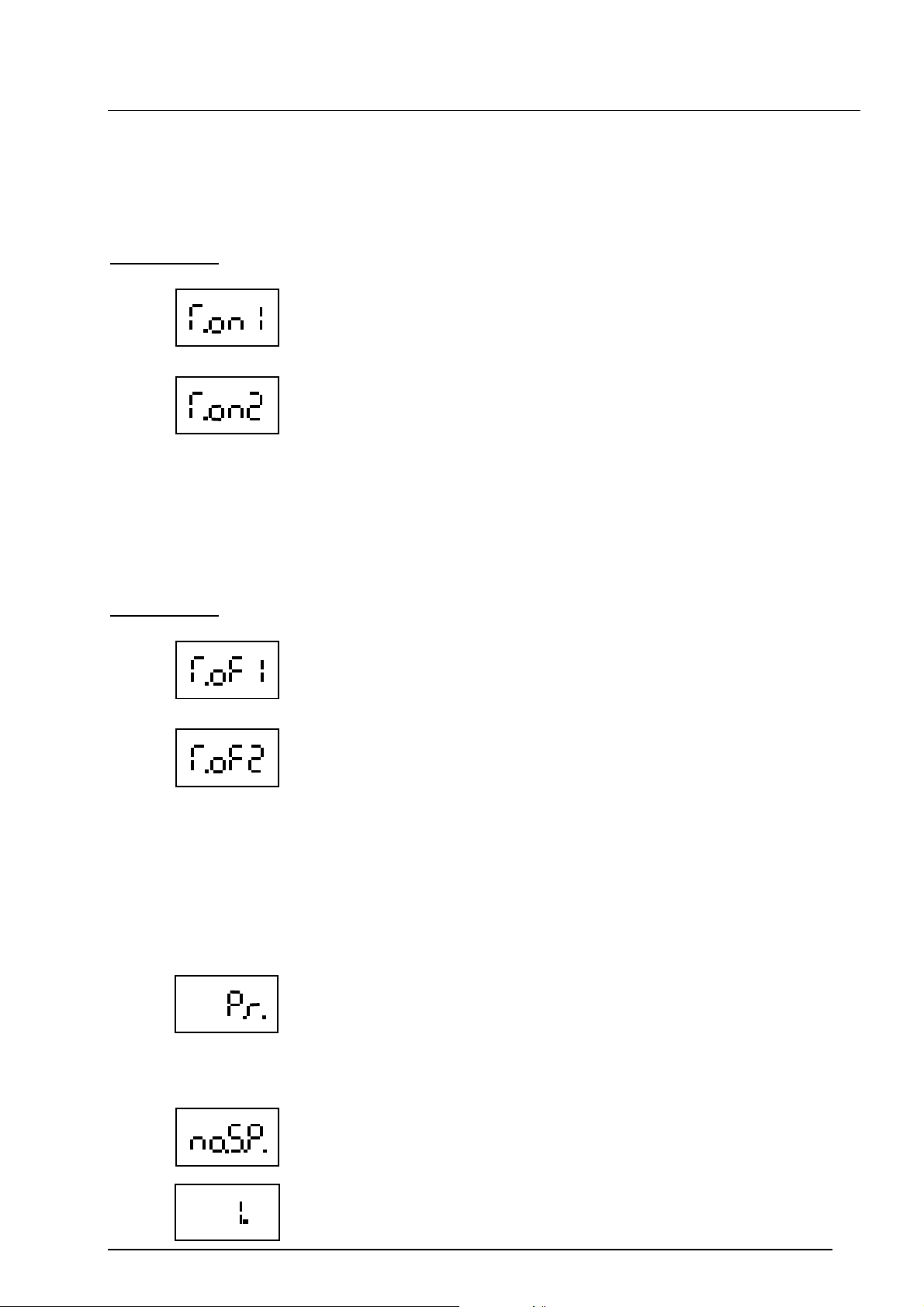
5
Page 31
Notice de programmation HYDAC de “HPG 3000-000“ 12.12.2008
4.1.4 Temporisation à l’enclenchement
Temps en milli-secondes durant lequel la pression doit dépasser le seuil d'enclenchement
(sens montant) pour que la sortie commute.
Abréviations:
= Temporisation à l’enclenchement [ms] SP1
= Temporisation à l’enclenchement [ms] SP2
4.1.5 Temporisation au déclenchement
Temps en milli-secondes durant lequel la pression doit dépasser le seuil de
déclenchement (sens descendant ) pour que la sortie commute vers l’état repos.
Abréviations:
= Temporisation au déclenchement [ms] SP1
= Temporisation au déclenchement [ms] SP2
4.2 Réglages spécifiques
On peut facilement contrôler des informations dans le menu de l’appareil.
Elles sont délivrées de la façon suivante:
- Plage mesure (Pressure Range)
= indique la plage mesure de l‘ EDS 4000 raccordé.
- Nombre de sortie de commutation
= nombre de sortie de commutation de l‘ EDS 4000
= L’EDS 4000 connecté dispose d’une sortie de commutation
6
Page 32
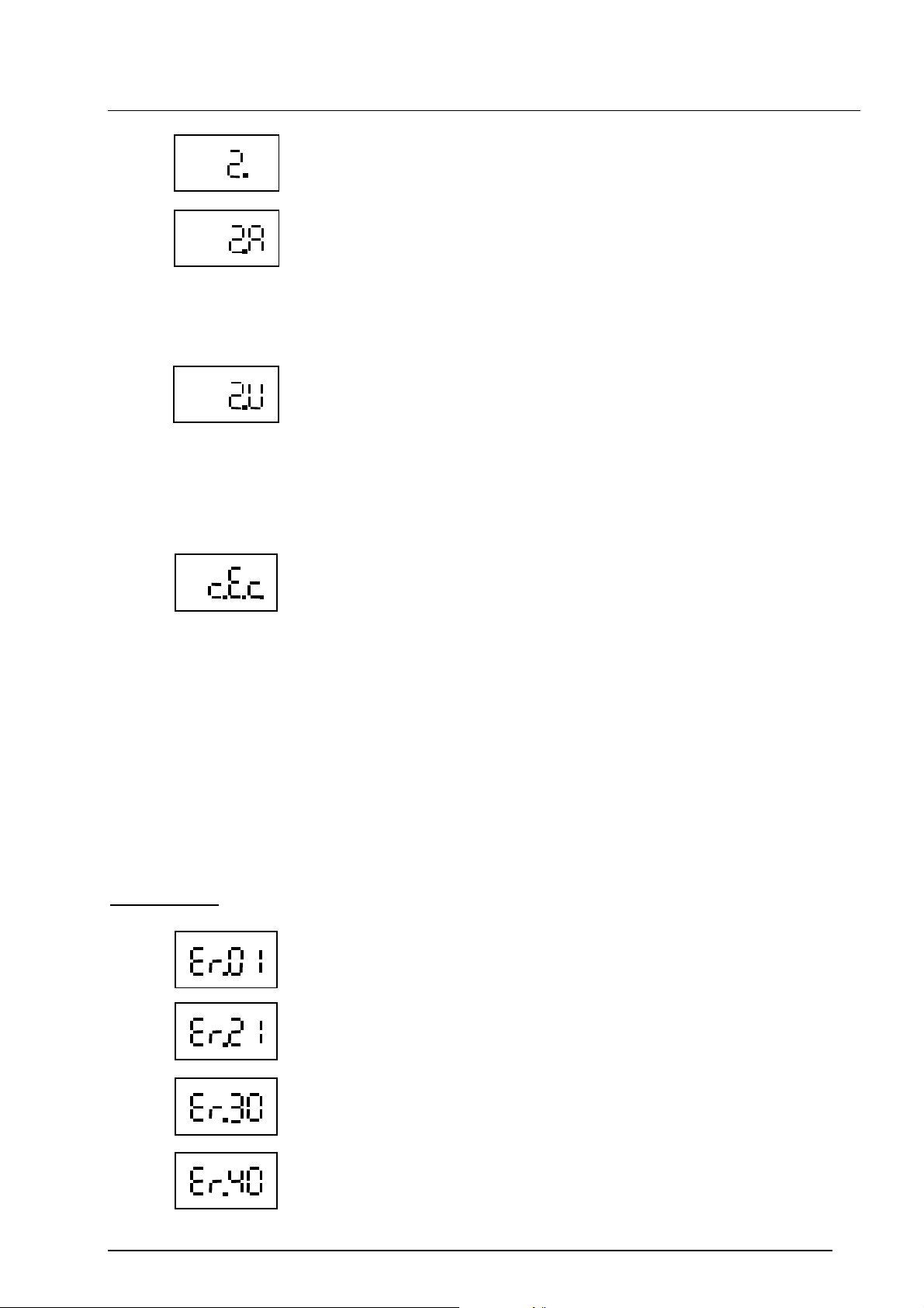
Notice de programmation HYDAC de “HPG 3000-000“ 12.12.2008
= L’EDS 4000 connecté dispose de 2 sorties de commutation
= L’EDS 4000 connecté dispose de 2 sorties de commutation.
SP1 HYS1, T.on 1 et T.of1 vers la sortie de commutation 1 sont
réglables, Les valeurs sont reprises pour SP2, HYS2, T.on2 et
T.of2 pour la sortie de commutation 2.
La restitution du signal des sorties de commutation se fait de
manière antivalente.
= L’EDS 4000 connecté dispose de 2 sorties de commutation.
SP1 HYS1, T.on 1 et T.of1 vers la sortie de commutation 1 sont
réglables, Les valeurs sont reprises pour SP2, HYS2, T.on2 et
T.of2 pour la sortie de commutation 2.
La restitution du signal des sorties de commutation se fait de
manière valente.
- Compteur d’évènement
= compteur de changement réglage
Ce compteur va incrémenté de 1, dès que l‘EDS 4000 est
reprogrammé.
5. Messages d‘erreur
Si le seuil de commutation et le réglage d’hystérésis ne sont pas cohérents (ex hystérésis
> seuil de commutation), le message d’erreur “Er.01” est affiché. Le réglage du seuil de
commutation et de l’hystérésis sont à corriger.
Si aucun EDS 4000 n’est raccordé lors de tentative de transfert de donnée, un message
d’erreur “Er.21” apparaît:
mode – touche pour acquitter le défaut
Er.21 = problème de liaison EDS 4000 (erreur de communication)
Abréviations:
= Mauvais réglage seuil de commutation / Hystérésis
= problème de liaison EDS 4000 ou erreur de communication
= Nombre de sorties de commutation incorrectes pour l’EDS 4000
connecté.
= L’EDS 4000 connecté dispose d’une fonction fenêtre.
(Un EDS 4000 avec cette modification ne peut être programmé
avec le HPG 3000)
7
Page 33
Notice de programmation HYDAC de “HPG 3000-000“ 12.12.2008
mod e
mod e
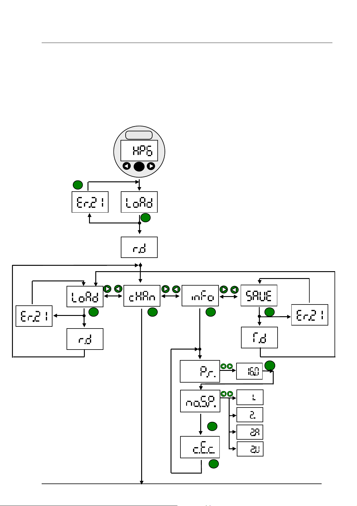
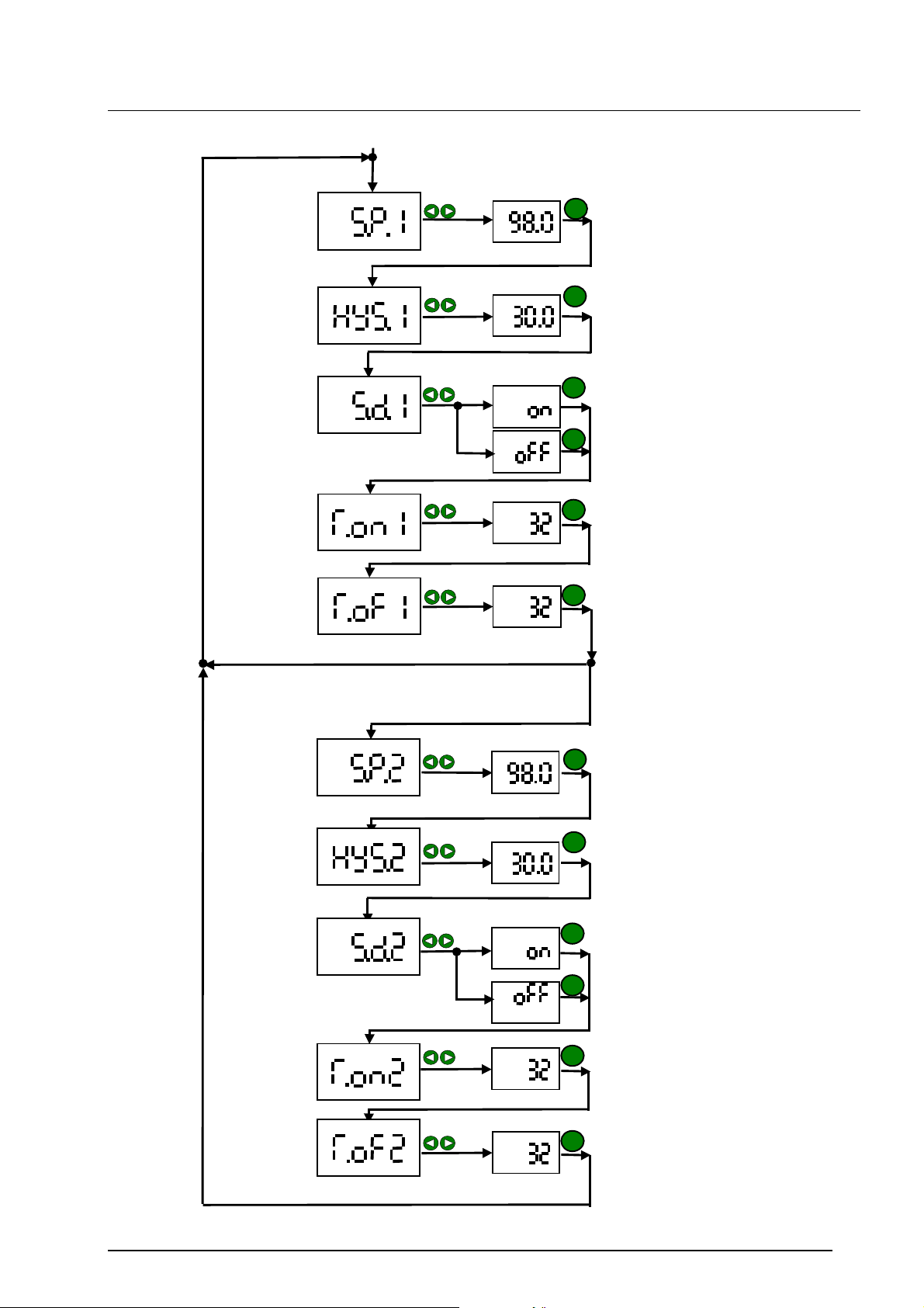
6. HPG 3000 – Diagramme de fonctionnement
Après le branchement de l’HPG 3000, la mise sous tension de l’EDS 4000 est effectuée.
Vous pouvez ensuite naviguer dans le menu.
Remarque: après 5s sans appui sur une touche, l’appareil retourne dans le menu
principal, les changements sont validés:
HYDAC
mode
mod e mod e
mod e
mod e
mod e
8
Page 34
Notice de programmation HYDAC de “HPG 3000-000“ 12.12.2008
m
ode
mode
mode
mode
mode
mode
EDS 4000 avec 2 sorties indépendante
mode
mode
mode
mode
mode
9
Page 35
Notice de programmation HYDAC de “HPG 3000-000“ 12.12.2008
. Activer
Remarque:
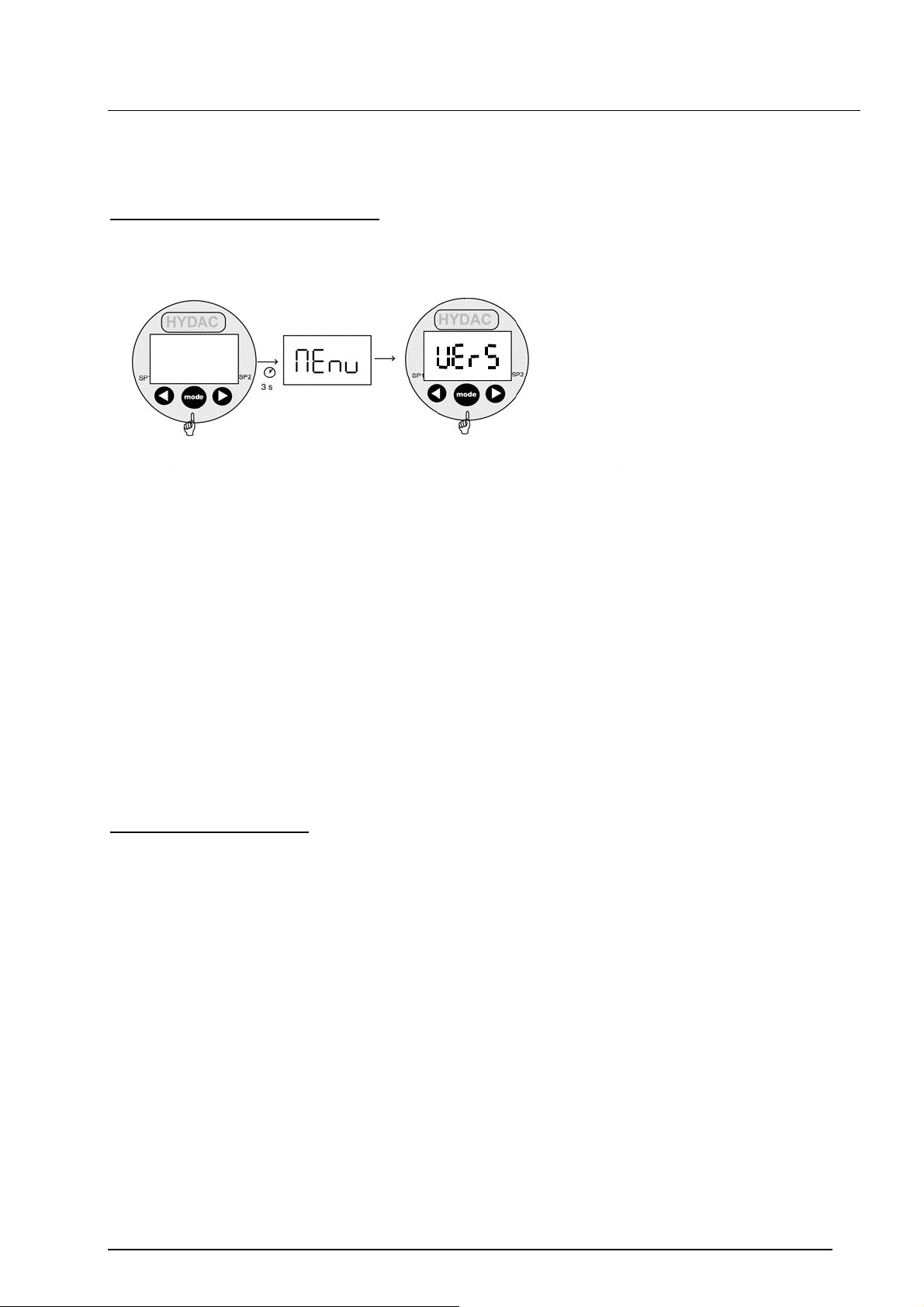
Dans le menu principal de l’HPG 3000, le numéro de version du programmateur est
enregistré.
Affichage du numéro de version.
Appuyer sur la
touche mode et la
maintenir
la tension
d‘alimentation
Laisser
appuyée la
touche jusqu’à
ce que „Menu“
s‘affiche sur
l‘écran.
Quitter le menu pricipal:
Sélectionner „END“ avec la touche mode. Choisir „Yes“ avec les touches ou et
confirmer avec mode.
Affichage
(Lâcher la
touche
„mode“)
Le numéro de
version de l’HPG
3000 apparaît
sur l‘écran .
10
Page 36
Notice de programmation HYDAC de “HPG 3000-000“ 12.12.2008
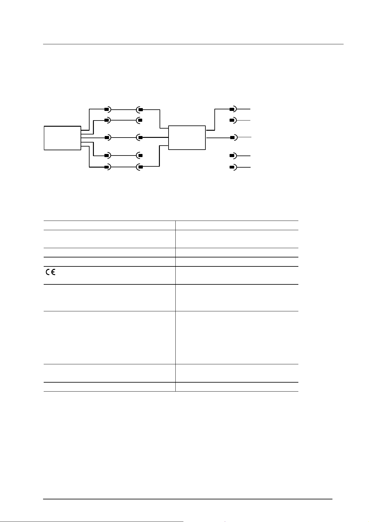
7. Schéma de raccordement
Branchement de l’EDS 4000 programmable sur le module de programmation HPG 3000:
1
+Ub
1
+Ub
1
EDS 4000
2
3
4
5
0 V
Comport
2
3
4
5
HPG 3000
2
0
3
4
5
V
8. Données techniques
Tension d’alimentation: 12 .. 35 V
Consommation de courant intrinsèque
35 mA
DC
:
Température ambiante : -25 .. + 80 °C
Température de stockage : -40 .. + 80 °C
-sigle: EN 61000-6-1, EN 61000-6-2,
EN 61000-6-3, EN 61000-6-4
Branchement alimentation : Connecteur M12x1, 4-pôles
Pin 1: +U
B
Pin 3: 0 V
Branchement programmation : Embase M12x1, 5-pôles
Pin 1: +U
B
Pin 2: non connecté
Pin 3: 0 V
Pin 4: non connecté
Pin 5: CP
Affichage: 4-digits, LED, 7-Segments rouge,
hauteur 7 mm
Poids: env. 120 g
9. Accessoires
ZBE 30-02 câble M12x1, longueur 2m (Nr.: 6040851)
ZBE 30-05 câble M12x1, longueur 5m (Nr.: 6040852)
11
Page 37
Notice de programmation HYDAC de “HPG 3000-000“ 12.12.2008
5
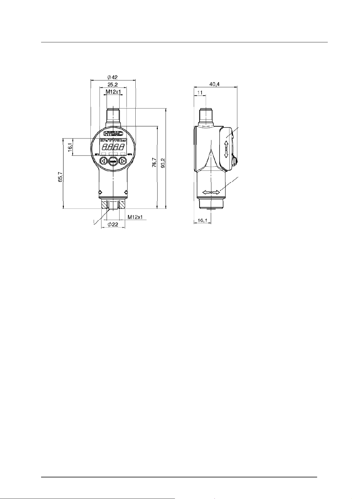
10. Dimensions de l’appareil
Affichage rotatif 270°
Orientation corps 340°
Embase 5 pôles
HYDAC ELECTRONIC GMBH
Hauptstr. 27
D-66128 Saarbrücken
Germany
Tel.: +49-(0)6897-509-01
Fax: +49-(0)6897-509-1726
HYDAC Service
Service après vente
HYDAC SERVICE GMBH
Hauptstr. 27
D-66128 Saarbrücken
Germany
Tel.: +49-(0)6897-509-1936
Fax: +49-(0)6897-509-1933
Remarque:
Les données de ce prospectus se réfèrent aux conditions de fonctionnement et
d’utilisation décrites. Pour des conditions de fonctionnement et d’utilisation différentes,
veuillez vous adresser au service technique compétent.
Pour toute question technique, veuillez vous adresser à la société Hydac.
Sous réserve de modifications techniques.
12
 Loading...