

Hydac HMG 4000 Operating Manual
Portable Data Recorder
HMG 4000
Operating Manual
(Translation of original instructions)

Content HMG 4000
Edition 2016-03-08 - V01 R04 [2] Part No.: 669950

Content HMG 4000
Edition 2016-03-08 - V01 R04 [3] Part No.: 669950
Preface ........................................................................................................................... 6
1 General ........................................................................................................................ 7
1.1 Standard functions ................................................................................................................... 7
1.2 CAN functions .......................................................................................................................... 9
1.3 Programming function for electronic switches ........................................................................ 9
1.4 Scope of delivery.................................................................................................................... 10
1.5 Technical Safety ..................................................................................................................... 10
1.6 Safety information ................................................................................................................. 11
1.7 Copyright protection .............................................................................................................. 11
1.8 Note on Warranty .................................................................................................................. 11
2 The HMG 4000 at a glance ......................................................................................... 12
2.1 Touchscreen and operating keys ........................................................................................... 12
2.2 Connection jacks .................................................................................................................... 13
3 first steps with the HMG 4000 ................................................................................... 14
3.1 Unpacking .............................................................................................................................. 14
3.2 Charging battery .................................................................................................................... 14
3.3 Switching device on and off ................................................................................................... 15
3.4 Updating firmware ................................................................................................................. 15
4 Managing the HMG 4000 ........................................................................................... 16
4.1 Touchscreen operation .......................................................................................................... 16
4.2 Display graphics setup ........................................................................................................... 16
4.3 Navigating in the menu/command bar (toolbar) ................................................................... 17
5 Quickstart .................................................................................................................. 18
5.1 Basic settings ......................................................................................................................... 18
5.2 Measured values .................................................................................................................... 20
5.3 Starting simple recording ....................................................................................................... 21
6 Start menu ................................................................................................................ 22
7 "Measured values" application ................................................................................. 23
7.1 Displaying measured channel information ............................................................................ 23
7.2 Settings for the measured value display .............................................................................. 27
7.3 Analogue inputs (A-H) ............................................................................................................ 31

Content HMG 4000
Edition 2016-03-08 - V01 R04 [4] Part No.: 669950
7.4 Digital inputs (I, J) .................................................................................................................. 34
7.5 CAN bus/HCSI (K) ................................................................................................................... 38
7.6 Calculations (L) ....................................................................................................................... 49
7.7 Further measurement settings .............................................................................................. 51
8 Recordings ................................................................................................................. 54
8.1 Starting a recording .............................................................................................................. 55
8.2 Recording procedure ............................................................................................................. 57
8.3 Operation during recording ................................................................................................... 68
8.4 Recordings ............................................................................................................................. 71
9 "Device settings" application ..................................................................................... 76
9.1 Region and language settings ................................................................................................ 76
9.2 Date and time settings ........................................................................................................... 76
9.3 Display settings ...................................................................................................................... 77
9.4 Graphic settings ..................................................................................................................... 77
9.5 Device information ................................................................................................................ 78
9.6 Manage settings .................................................................................................................... 78
10 "Stopwatch" application .......................................................................................... 81
11 "Programmable switches" application ..................................................................... 82
11.1 Article / Serial number ......................................................................................................... 83
11.2 Measured values .................................................................................................................. 83
11.3 Switch point settings ............................................................................................................ 83
11.4 Advanced settings ................................................................................................................ 84
11.5 Managing settings ................................................................................................................ 85
12 "SMART sensor" application .................................................................................... 87
12.1 Connecting SMART sensors ................................................................................................. 88
12.2 SMART sensor menu ............................................................................................................ 89
13 "CAN Tools" application .......................................................................................... 92
13.1 Basic settings ....................................................................................................................... 93
13.2 Establishing connection ....................................................................................................... 94
14 "Screenshots" application ..................................................................................... 100

Content HMG 4000
Edition 2016-03-08 - V01 R04 [5] Part No.: 669950
15 "File Manager" application .................................................................................... 101
15.1 Working with the file manager .......................................................................................... 101
15.2 Restrictions to the file manager ......................................................................................... 104
15.3 PC Link ............................................................................................................................... 105
16 Cleaning / Maintenance / Update ......................................................................... 106
16.1 Cleaning ............................................................................................................................. 106
16.2 Maintenance / Calibration ................................................................................................. 106
16.3 Repair ................................................................................................................................. 106
16.4 Software update ................................................................................................................ 107
16.5 Changing battery ............................................................................................................... 109
16.6 DC-DC ground bond ........................................................................................................... 110
17 Accessories ............................................................................................................ 111
17.1 Sensors............................................................................................................................... 111
17.2 Sensor cables ..................................................................................................................... 112
17.3 Other accessories ............................................................................................................... 112
17.4 Spare parts ......................................................................................................................... 112
18 Technical data ....................................................................................................... 113
18.1 Input channels ................................................................................................................... 113
18.2 Programming interface ...................................................................................................... 114
18.3 Supply voltage.................................................................................................................... 114
18.4 Display ............................................................................................................................... 114
18.5 Interfaces ........................................................................................................................... 115
18.6 Memory ............................................................................................................................. 115
18.7 Technical standards ........................................................................................................... 115
18.8 Ambient conditions............................................................................................................ 115
18.9 Port allocations .................................................................................................................. 116
18.10 Dimensions and weight.................................................................................................... 117

Preface HMG 4000
Edition 2016-03-08 - V01 R04 [6] Part No.: 669950
Preface
This manual provides you, as user of our product, with key information on the operation
and maintenance of the equipment.
It will acquaint you with the product and assist you in obtaining maximum benefit in the
applications for which it is designed.
Keep the manual in the vicinity of the instrument for immediate reference.
Please note: the specifications given in this documentation regarding the instrument
technology were correct at the time of publishing.
Modifications to technical specifications, illustrations and dimensions are therefore
possible.
If you discover errors while reading the documentation or have additional suggestions or
tips, please contact us at:
HYDAC ELECTRONIC GMBH
Technical Documentation
Hauptstrasse 27
66128 Saarbruecken
-Germany-
Phone: +49 (0) 6897-509-01
Fax: +49 (0) 6897-509-1726
Email: electronic@hydac.com
We look forward to receiving your input.
“Putting experience into practice”

General HMG 4000
Edition 2016-03-08 - V01 R04 [7] Part No.: 669950
1 General
This manual is a constituent part of the device. It contains texts and graphics concerning
the correct handling of the product and must be read before operation of the device.
The manual offers information concerning the safe operation of the portable data
recorder HMG 4000.
By using this manual as recommended, you will ensure that the HMG 4000 is put into
effective and safe operation as quickly as possible.
1.1 Standard functions
The HMG 4000 portable data recorder is a mobile measurement and data gathering
device for measuring tasks for hydraulic and pneumatic systems and machines as well as
in industrial and mobile areas.
The applications are primarily to be found in the areas Service, Maintenance, Faultfinding or in the test bench area.
The HMI 4000 can record the signals of up to 38 sensors at once.
For this purpose, HYDAC ELECTRONIC offer special sensors, which are automatically
detected by the HMG 4000 and whose parameters such as measurement values,
measuring ranges and measuring units can be set.
On the one hand, there are the HYDAC HSI-Sensors (HYDAC Sensor Interface) for the
measurement of pressure, temperature and flow rate, for the connection of which there
are 8 analogue input channels.
Furthermore, there is the option of connecting HYDAC SMART sensors to these inputs.
SMART sensors can display several different measured variables at a time.
Up to 28 special HYDAC HCSI-Sensors (HYDAC CAN Sensor Interface) can be connected
additionally via the CANbus port, also supporting automatic sensor detection.
HMG 4000 can optionally be connected to an existing CAN network. This enables the
recording of measured data transmitted via CAN bus (e.g. motor speed, motor pressure)
in combination with the measured data from the hydraulic system.
Older model HYDAC sensors or commonly available sensors made by other
manufacturers can also be used. However, these sensors do not have any automatic
sensor detection, consequently the initial set-up has to be entered manually.

General HMG 4000
Edition 2016-03-08 - V01 R04 [8] Part No.: 669950
The device also offers measurement inputs for standard sensors with current and voltage
signals.
The HMG 4000 rounds off the application, providing two additional digital inputs (e.g. for
frequency or rpm measurements).
The HMG 4000 can render up to 100 measurement channels in total.
Depending on the type of sensor, there is an internal memory in the sensor for the
storage of recorded measurement data on a long-term basis. In addition, depending on
the sensor type, pre-set parameters can be changed and stored in the internal memory
as a sensor configuration.
The operator can intuitively access all of the unit’s functions and settings by means of
clearly presented selection menus. The HMG 4000 has a touchscreen similar to that of a
mobile phone or tablet computer for the purpose of entering number values and text.
When taking measurements of rapid, dynamic machine processes, all 8 analogue input
signals can be recorded simultaneously at a rate of 0.1 ms.
This function of course requires suitable fast sensors to be used.
The most impressing feature of the HMG 4000 is its ability to record the dynamic
processes of a machine in the form of a measurement curve and render them as a graph
— and, moreover, online and in real time.
The HMG 4000 is equipped with specially developed software providing for fast data
collection and processing. A measurement curve can comprise
up to 8 million measured values. The measured value memory for archiving this data can
record more than 500 measurement curves of this type.
Alongside simple measurement curves for single and endless recordings, the HMG 4000
has additional functions for recording event-controlled measurements and event logs.
There are various trigger options available for triggering events.

General HMG 4000
Edition 2016-03-08 - V01 R04 [9] Part No.: 669950
Alongside measurement curve recording, it is possible to create and save user-specific
settings, so-called user profiles. The main advantage of this is to enable identical
measurements of various equipment items to be repeated for the purpose of preventive
maintenance. All the user has to do is retrieve the relevant user profile from the HMG
4000’s memory.
For visualisation purposes, the HMG 4000 has a fully graphic-enabled 5.7" touchscreen
for displaying the shown measured values clearly as text or as a measurement curve. A
very large format display of individual measured values is also possible in order to be
able to read them from greater distances.
The HMG 4000 is equipped with numerous user-friendly functions for displaying,
evaluating and processing measured values:
• Table
• Graphics
• Scaling
• Tracker
• Zoom
The HMG 4000 communicates with a PC via the integrated USB device interface.
For the subsequent easy editing, display and evaluation of the measurements on a PC,
you can use the HMG 4000's "HMGWIN" software which is included in the scope of
delivery. This also permits the (remote) control of the HMG 4000 directly from the
computer.
The HYDAC software CMWIN is also supplied as standard with the unit. This software
enables you to communicate directly from your PC with SMART sensors connected to the
HMG 4000.
1.2 CAN functions
• Port option to CAN bus
• Read-out and evaluation of up to 28 measured values from up to 28 CAN messages
• Configuration of CAN sensor measured values
• Connection of up to 28 HYDAC HCSI sensors
• For further functions, see "CAN Tools" menu
1.3 Programming function for electronic switches
Programmable electronic print, temperature and level switches with IO link (EDS 8xx /
ExS 3xxx) as well as the HPG P1-000 can be easily programmed and parametrised via the
programming function of the HMG 4000.

General HMG 4000
Edition 2016-03-08 - V01 R04 [10] Part No.: 669950
1.4 Scope of delivery
• HMG 4000
• Power supply for 90 ... 230 V connection
• Instruction manual
• Data carrier with USB drivers, the software "HMGWIN" and "CMWIN"
(software for evaluating measured data or sensor communication)
as well as other product information
• USB connection cable
• Harness
1.5 Technical Safety
The individual components of the HMG 4000 portable data recorder and the assembled
unit are subject to strict quality assurance inspection and testing. Each HMG 4000
undergoes a final test. This ensures that upon delivery, the unit is free from defects and
complies with the designated specifications.
The series HMG 4000 portable data recorders are maintenance-free and work perfectly
when used under the conditions specified. If, however, you do encounter problems,
please contact your HYDAC representative.
Any tampering with the switch will cause all warranty claims to become null and void.
Compliance with European Standards
The HMG 4000 series portable data recorders have the CE mark and thus comply with all
current German regulatory requirements and European standards relating to the
operation of these units. This ensures compliance with the applicable directives relating
to electromagnetic compatibility and the safety provisions according to the low-voltage
directive.
This product is in compliance with the regulations contained in the following European
guidelines:
EN 61000-1 / 2 / 3 / 4.
We reserve the right to make technical modifications.

General HMG 4000
Edition 2016-03-08 - V01 R04 [11] Part No.: 669950
1.6 Safety information
The HMG 4000 series Portable Data Recorder can be operated safely provided it is used
in accordance with its proper, designated use. Please maintain strict adherence to the
following safety guidelines in order to preclude hazards to the user and damage to
property and surroundings as the result of improper use:
• The HMG 4000 may not be used unless it is in perfect condition/working order.
• The instructions for use must be strictly adhered to. Functions which involve adjusting
the zero point in particular can lead to hazardous situations. For more information,
please refer to Point 7.1.5 "Zeroing of Measurement Channels".
• If sensors and interfaces are used simultaneously (online measurement), please ensure
equipotential.
• The information on the name plate must be noted.
• Troubleshooting and repair work may only be carried out at the HYDAC Service
Department.
• All relevant and generally recognised safety requirements must be adhered to.
1.7 Copyright protection
The dissemination and/or reproduction of this document, as well as the exploitation and
communication of its content, is not permitted unless specifically authorized.
Any violations hereof will be prosecuted to the maximum extent possible under the law.
All rights reserved.
1.8 Note on Warranty
This manual was compiled with the greatest possible care. Nevertheless, errors or
deviations cannot be excluded, and for this reason we assume no responsibility for the
complete accuracy of the content.
In view of the fact that, despite intensive endeavours, errors can never be completely
avoided, we welcome tips and suggestions for improvement at any time.
Device Description HMG 4000
Edition 2016-03-08 - V01 R04 [12] Part No.: 669950
2 The HMG 4000 at a glance
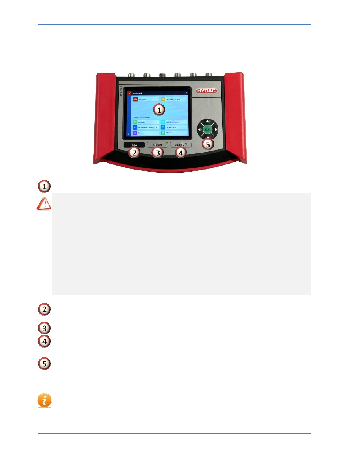
2.1 Touchscreen and operating keys
Touchscreen
Only use your fingers to touch the touchscreen!
Make sure the touchscreen does not come into contact with electrical devices as
electrostatic discharges can cause malfunctions on the touchscreen.
Make sure the touchscreen does not come into contact with liquids. Dampness or
contact with liquids can cause malfunctions on the touchscreen.
To prevent damage to the touchscreen, do not use sharp or pointy objects on it and
do not apply heavy pressure.
A few simple gestures (tap, stroke and drag movements as well as expanding and
shrinking) are all you need to operate the touchscreen. Notes can be found in
Chapter 4.1 "Touchscreen operation".
ESC key
To cancel an entry or go Back step by step
On/off button
Brightness setting Touchscreen
Quick press: Switch display on/off; Long press: Set brightness
5-way navigation key
Step-by-step navigation inside the display: "o.k." key for entering, completing,
transferring or saving input
Alternatively to the touchscreen, the HMG 4000 can be operated using the ESC key
and the navigation and directional pad.
Device Description HMG 4000
Edition 2016-03-08 - V01 R04 [13] Part No.: 669950
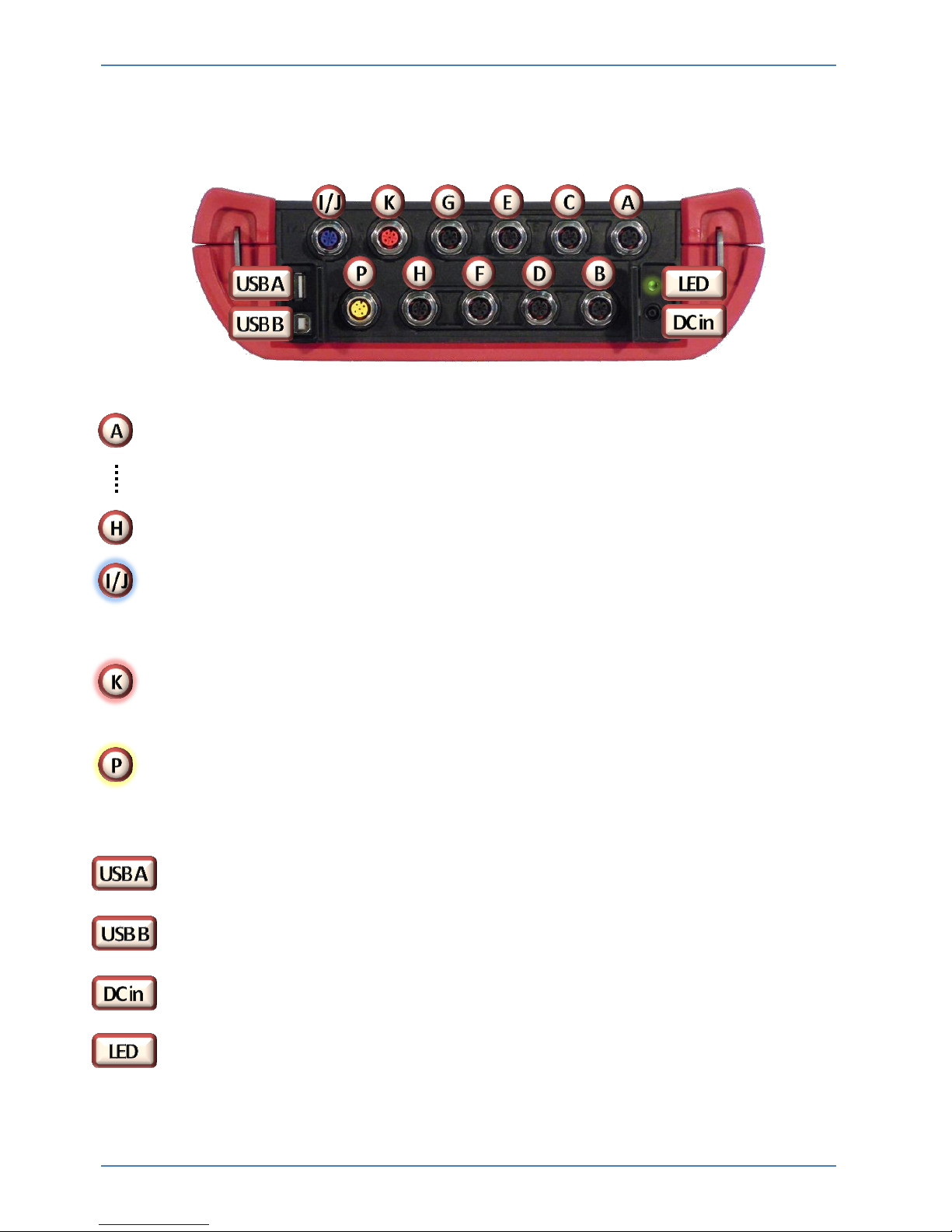
2.2 Connection jacks
Analogue inputs (black)
8 input jacks (Channels A-H) for connecting normal analogue sensors
(0-10 V, 4-20 mA, …), as well as HYDAC HSI sensors or SMART sensors,
for example for measuring print, temperature, flow rate or
oil condition.
Digital inputs (blue)
1 input jack for 2 digital signals (Channel I, J), e.g. for frequency or speed
measurements
CAN bus/HCSI (red)
1 connection jack for CAN bus and HYDAC HCSI sensors (channel K)
Programming connection (yellow)
1 connection jack for programmable, electronic HYDAC pressure, temperature and
level switches
USB host for connecting slaves (e.g. USB memory stick)
USB Device for PC connection
Female jack for power supply
LED display for battery charge
First Steps HMG 4000
Edition 2016-03-08 - V01 R04 [14] Part No.: 669950
3 first steps with the HMG 4000
3.1 Unpacking
The HMG 4000 is supplied in a cardboard box. When accepting and unpacking, make
sure the item has been delivered in full and look out for any possible transport damage.
If present, show it to the shipper.
3.2 Charging battery
Charge the battery with the help of the power supply unit provided before using the
HMG 4000 for the first time.
The battery built into the HMG 4000 starts charging as soon as the measuring device is
supplied with power by the power adapter provided.
Only use the batteries, power adapters and cables supplied or authorised for use
by HYDAC.
Not permitted batteries, chargers and cables can lead to overheating or explosion
of the battery or to damage to the HMG 4000.
If the battery charge is low, a corresponding warning message appears on the
display.
If the battery is completely empty, the HMG 4000 cannot be switched on directly
after connecting the power adapter. Charge the empty battery for a few minutes
first before switching the HMG on again.
Incorrectly connecting the power adapter can lead to damage to the device.
Damage through improper use is not covered by the warranty.
The device can heat up when charging. This is normal and does not affect the function,
performance or service life of the HMG 4000.
If the battery gets hotter than normal, unplug the power adapter.
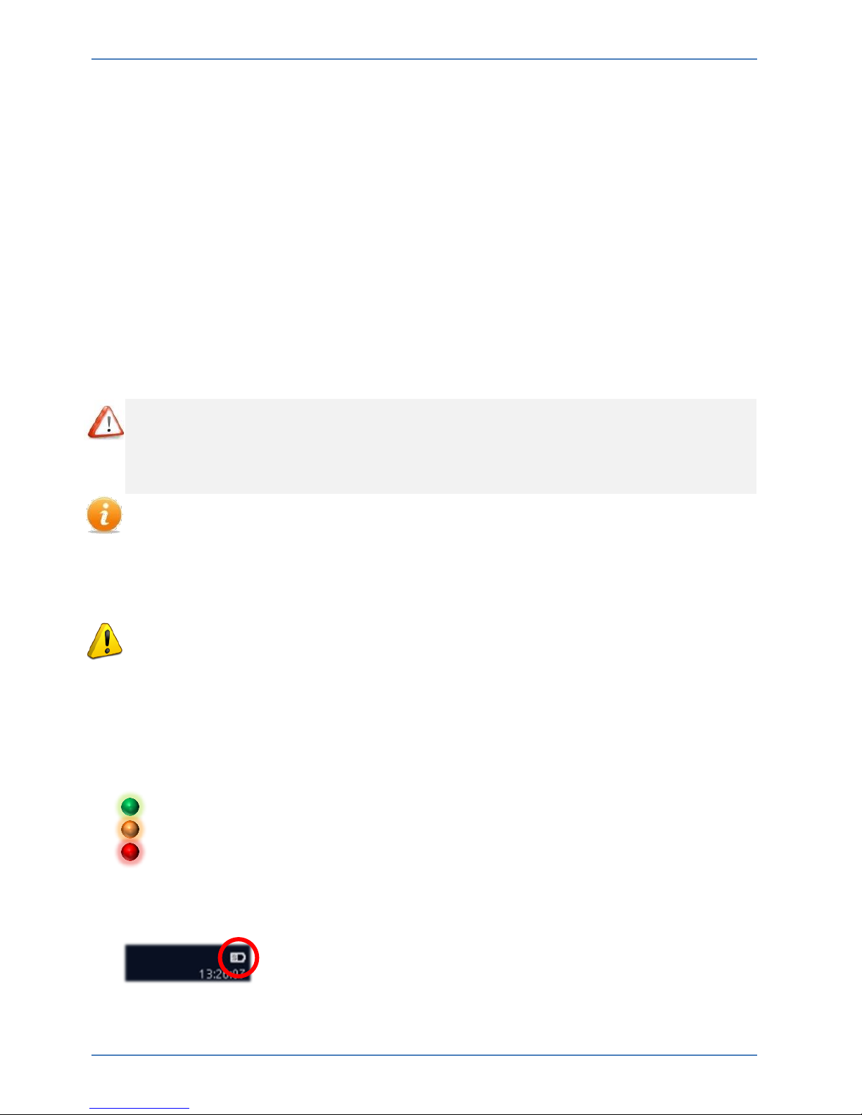
The charge of the battery is shown by the integrated LED beside the connection jack:
Green = Battery fully charged
Orange = Battery charging
Red = Error
The current charge is also shown in the display to the top right if the device is switched
on.

First Steps HMG 4000
Edition 2016-03-08 - V01 R04 [15] Part No.: 669950
3.3 Switching device on and off
After switching on the HMG 4000 for the first time, follow the instructions on the display
and adjust the necessary basic settings on the "Welcome screen".
3.4 Updating firmware
To have the latest version of the HMG 4000 the firmware of the device needs to be
updated provided an update file is available.
Under certain circumstances, the settings saved in the HMG 4000 may no
longer be legible after installing an update.
Corresponding notices appear on the display before the update is executed.
If necessary, back up this data on a PC before starting the update.
Connect the power adapter to the HMG 4000 in order to guarantee a safe and
interruption-free power supply during the update process.
Detailed information on the firmware update can be found in chapter 16.4
"Software update"
Handling HMG 4000
Edition 2016-03-08 - V01 R04 [16] Part No.: 669950
4 Managing the HMG 4000
4.1 Touchscreen operation
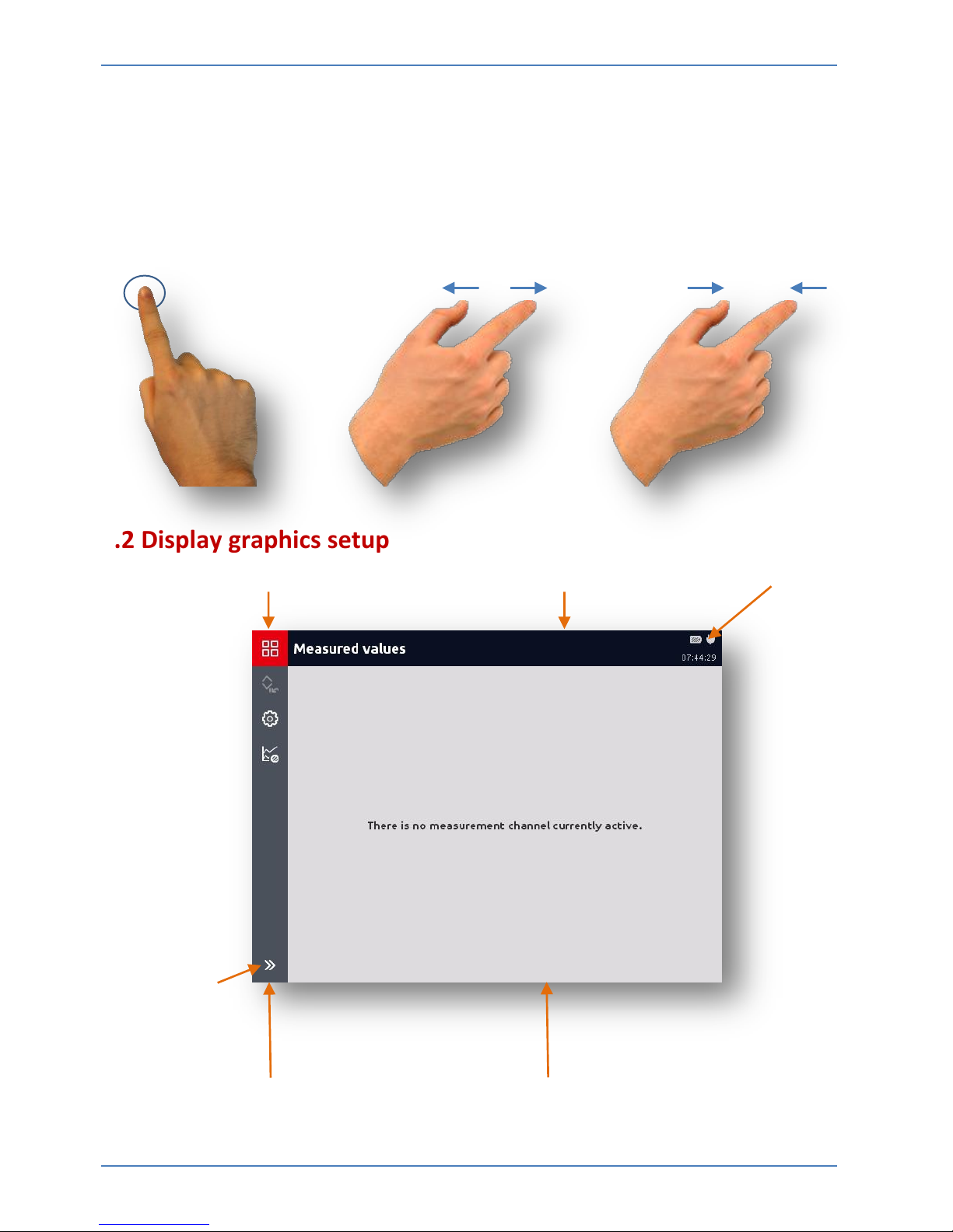
The use and operation of the touchscreen is done with a few simple gestures (tap,
swipe and drag movements as well as expanding and shrinking):
Tap / Drag Expand Shrink
4.2 Display graphics setup
Start button (start menu) / Back button Display bar Battery charge status
Info and help
Show texts /
Generate
screenshot
Menu/Command bar (toolbar) Display/Selection field
Handling HMG 4000
Edition 2016-03-08 - V01 R04 [17] Part No.: 669950
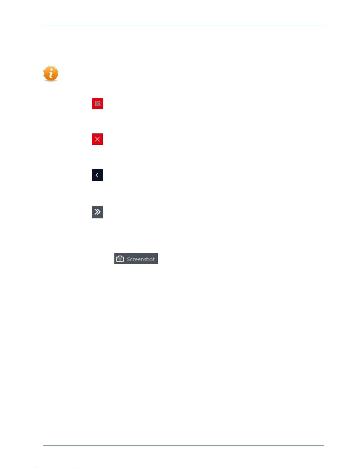
4.3 Navigating in the menu/command bar (toolbar)
All settings and input options in the different applications and function menus of
the HMG 4000 are largely self-explanatory and can be used intuitively.
Using the button, you can directly access every display and from every menu
point you can access the "Start menu".
Using the button, you can access the most recently started application / menu
page / display directly from the start menu.
Using the button at the top of the display bar, you can always go back to the
previous page in all of the menus and displays.
Using the button to the bottom of the menu/command bar you can show or
hide the information texts on the individual command buttons (icons) and/or the
current application.
Additionally, the button appears, which you can use to directly
generate a screenshot of the current screen content.
Quickstart HMG 4000
Edition 2016-03-08 - V01 R04 [18] Part No.: 669950
5 Quickstart
5.1 Basic settings
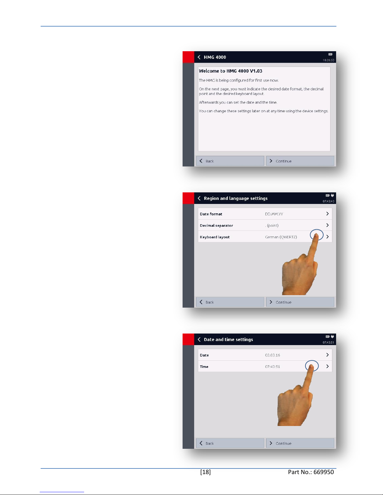
When starting the unit up for the
first time the Welcome start-up
screen appears.
You now have to adjust the "Basic
settings" required for the device to
work.
Select the desired date format,
decimal point and keyboard layout.
Complete the operation with
"Continue" or go back to the
previous screen by pressing "Back".
Enter the date and time.
Complete the operation with
"Continue" or go back to the
previous screen by pressing "Back".

Quickstart HMG 4000
Edition 2016-03-08 - V01 R04 [19] Part No.: 669950
The entry of basic settings is now
finished and you can use the HMG
4000.
Complete the operation with
"Finish" or go back to the previous
screen by pressing "Back".
The display then jumps to the
measured value display.
If there is no sensor connected, the
following message will appear on
the display
"No measurement channel currently
active".
By tapping the battery/time field in
the display bar, the adjacent "Status
window" will open.
This provides information on the
current charge status as well as on
the currently set date and time.
Date and time can be changed here.
Quickstart HMG 4000
Edition 2016-03-08 - V01 R04 [20] Part No.: 669950
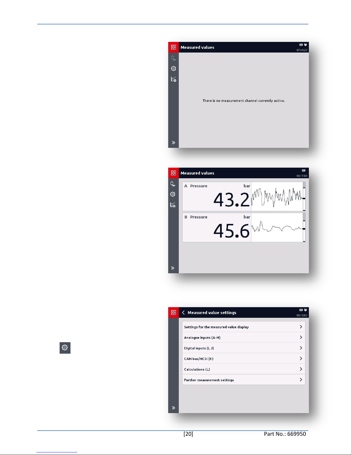
5.2 Measured values
If there is no sensor connected, the
following message will appear on
the display
"No measurement channel currently
active".
In delivery status, all eight analogue
inputs are preset to "Automatic
sensor detection" mode.
If a HYDAC HSI or SMART sensor is
now connected to one of the
channels A-H, this is automatically
detected and displayed accordingly.
In the measured value display (see
right), you will find the following
listed:
Input channel - Designation - Unit Measured value
To be able to make changes to the
measured value settings or
measured channels, you can access
the "Measured value settings" menu
via the button.
(For extensive information on this,
see chapter 7 "Measured value
application")
Quickstart HMG 4000
Edition 2016-03-08 - V01 R04 [21] Part No.: 669950
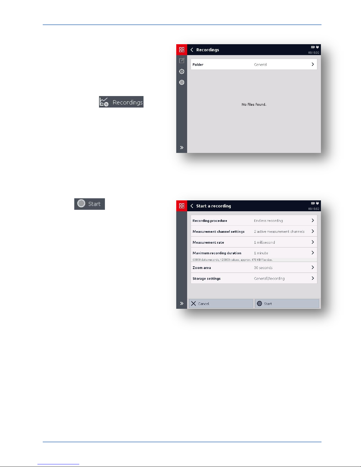
5.3 Starting simple
recording
To record measured value curves,
you can access the "Recordings"
menu from the measured value
display using the
button.
Using the button you can
access the "Start a recording"
menu.
You can adjust the corresponding
settings for the recording here.
(For extensive information on this,
see chapter 8 "Recordings")
Start Menu HMG 4000
Edition 2016-03-08 - V01 R04 [22] Part No.: 669950
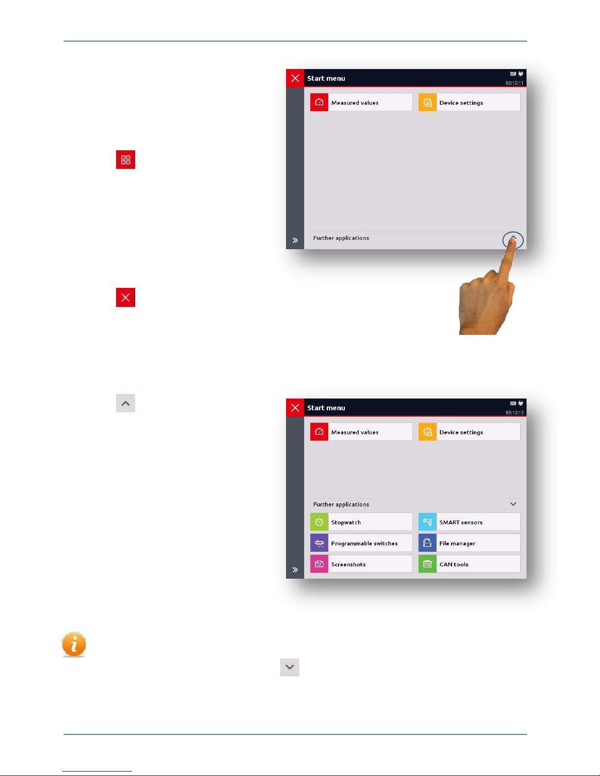
6 Start menu
After switching on the
HMG 4000, the screen will
automatically switch to the
measured value display.
Using the button you can access
the "Start menu".
In the basic setting, only the
following two applications are
shown:
- Measured values
- Device settings
Using the button, you can access the most recently started
application.
Using the button in the "Further
applications" field, additional
functions or applications of the
device will be shown
for selection:
- Stopwatch
- SMART sensors
- Programmable switches
- File manager
- Screenshots
- CAN tools
If "Further applications" is selected, this setting will remain. This means that when
you open the start menu, all of the applications and functions will always be
shown. You can reset this using the button.
Measured values HMG 4000
Edition 2016-03-08 - V01 R04 [23] Part No.: 669950
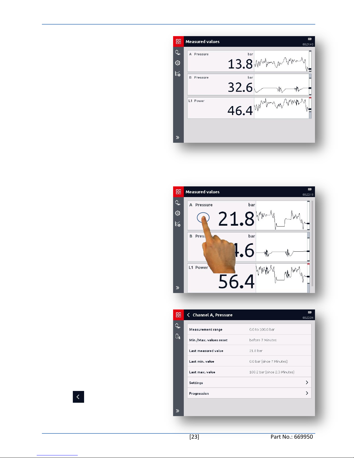
7 "Measured values"
application
If sensors are connected and the
channels set accordingly, their
current measured values will be
shown to you immediately.
The following details will be shown
to you by default in the measured
value display:
- Input channel (e.g. subchannel)
- Designation (sensor type)
- Unit
- Measured value
- History
7.1 Displaying measured
channel information
When you tap a measured value
field, a new window with detailled
information on the respective
measured channel will appear.
In this window, you will receive the
following information on the
measurement channel and the
connected sensor:
- Measurement range
- Min./Max. values reset
- Last measured value
- Last min. value
- Last max. value
- Settings:
Mode
Name
Sensor detection
- Progression
Using the button you can access
the measured value display again.
Measured values HMG 4000
Edition 2016-03-08 - V01 R04 [24] Part No.: 669950
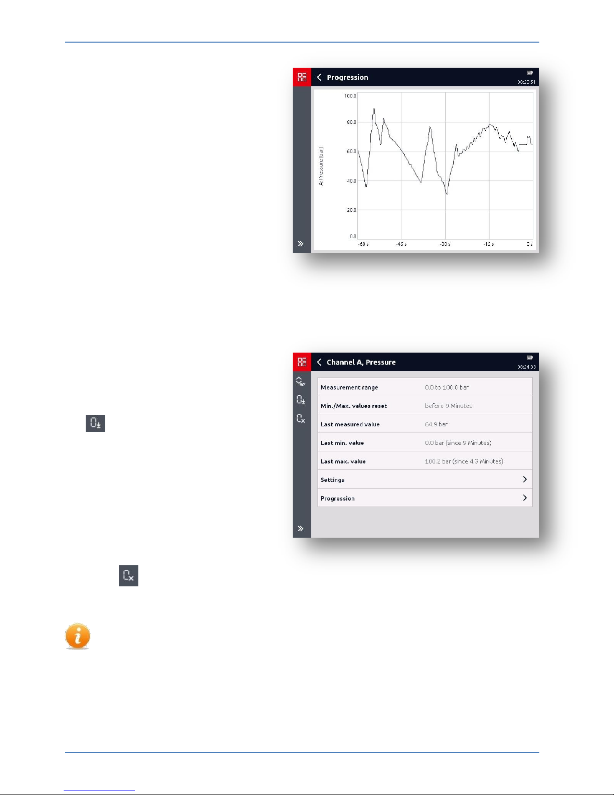
Using the "Progression" opens a
new window.
Here, the current history of the
measured values is shown as an
ongoing graphic.
(Also see chapter 7.2.5 "Display
progression")
7.1.5 Resetting measured value
zero point
You can re-specify the zero point via
the button.
This function can be used, for
example, in order to hide any
pressure heads in a system. In case
a pressure transducer still has, for
example, 3 bar of pressure even
when the system is switched off,
this value can be used as the new
zero point for the display.
Using the button, you can
delete the zero shift.
Re-zeroing can be done at any point throughout the measurement range of a
measurement channel.
Measured values HMG 4000
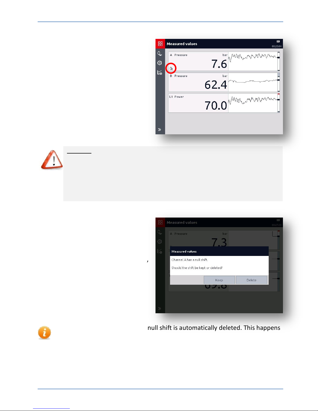
Edition 2016-03-08 - V01 R04 [25] Part No.: 669950
For safety reasons, all measurement
channels for which the zero point
was reset will be highlighted in the
measured value display with a
corresponding symbol.
Caution!
A high pressure may still be present in a measurement channel marked by
an arrow even though the display shows 0 bar.
When removing a sensor or other system components make sure the
system has been depressurized first.
Failure to do this may pose a hazard to life and limb.
Switching ON/OFF the HMG 4000 or
one or more measured channels does
not lead to the automatic deletion of
the newly set zero point.
If you switch the HMG off and on again,
you will receive a corresponding
message.
There is one exception where the null shift is automatically deleted. This happens
when a sensor is connected to the channel and this sensor has a different
measurement range to the one for which the null shift was set.
This means that the null shift is not retained unless the lower and upper
measurement limit, the number of decimal places, and the unit of measurement
of the newly connected sensor are identical.
Measured values HMG 4000
Edition 2016-03-08 - V01 R04 [26] Part No.: 669950
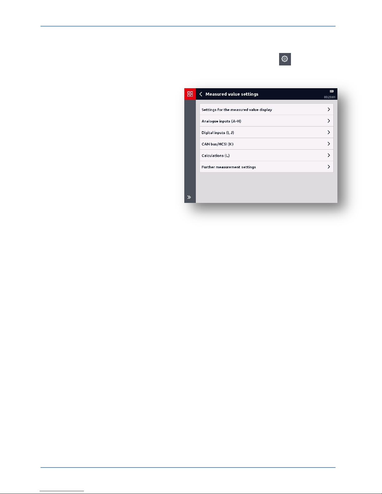
To make changes to the measured value settings or the measured channels, access the
measured value display in the "Measured value settings" menu via the button.
You can adjust the settings and
changes in the following menu
points via this window:
- Settings for the measured
value display
- Analogue inputs (A-H)
- Digital inputs (I, J)
- CAN-Bus/HCSI (K)
- Calculations (L)
- Further measurement
settings
Measured values HMG 4000
Edition 2016-03-08 - V01 R04 [27] Part No.: 669950
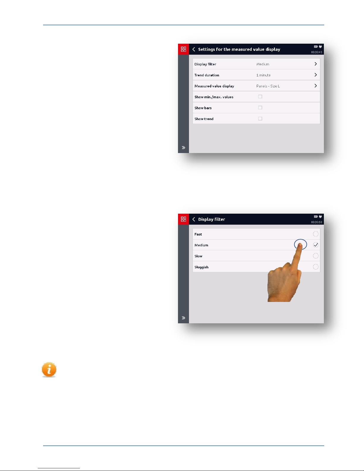
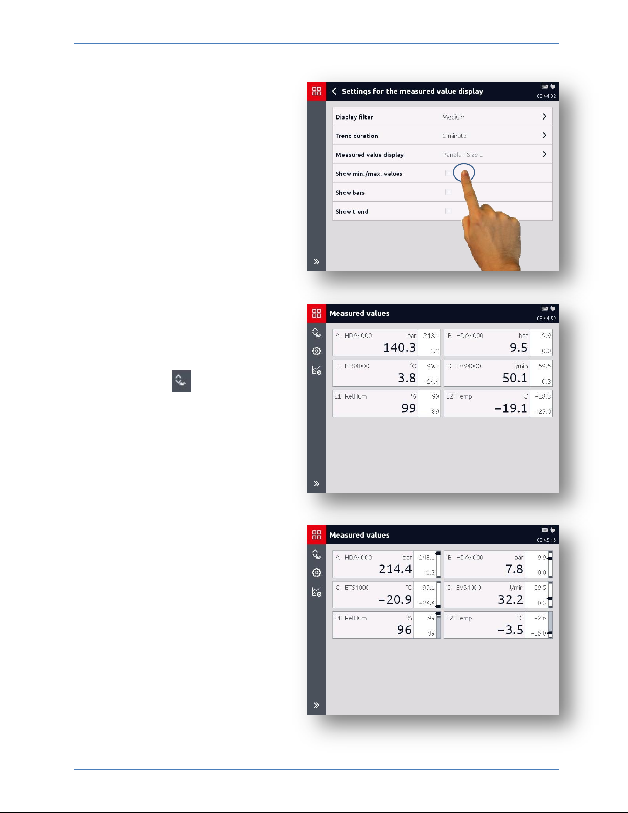
7.2 Settings for the
measured value display
You have the following setup options
under this menu point:
- Display filter
- Trend duration
- Measured values display
- Show min./max values
- Show bars
- Show trend
7.2.1 Display filter
With the selection of "Display
filter", a selection list for the display
dynamics will appear:
• Fast
• Medium
• Slow
• Sluggish
The settings for the display filter in the measured value display do not influence
the measurement itself! They solely serve to settle down the display, for example,
with pulsations.
Measured values HMG 4000
Edition 2016-03-08 - V01 R04 [28] Part No.: 669950
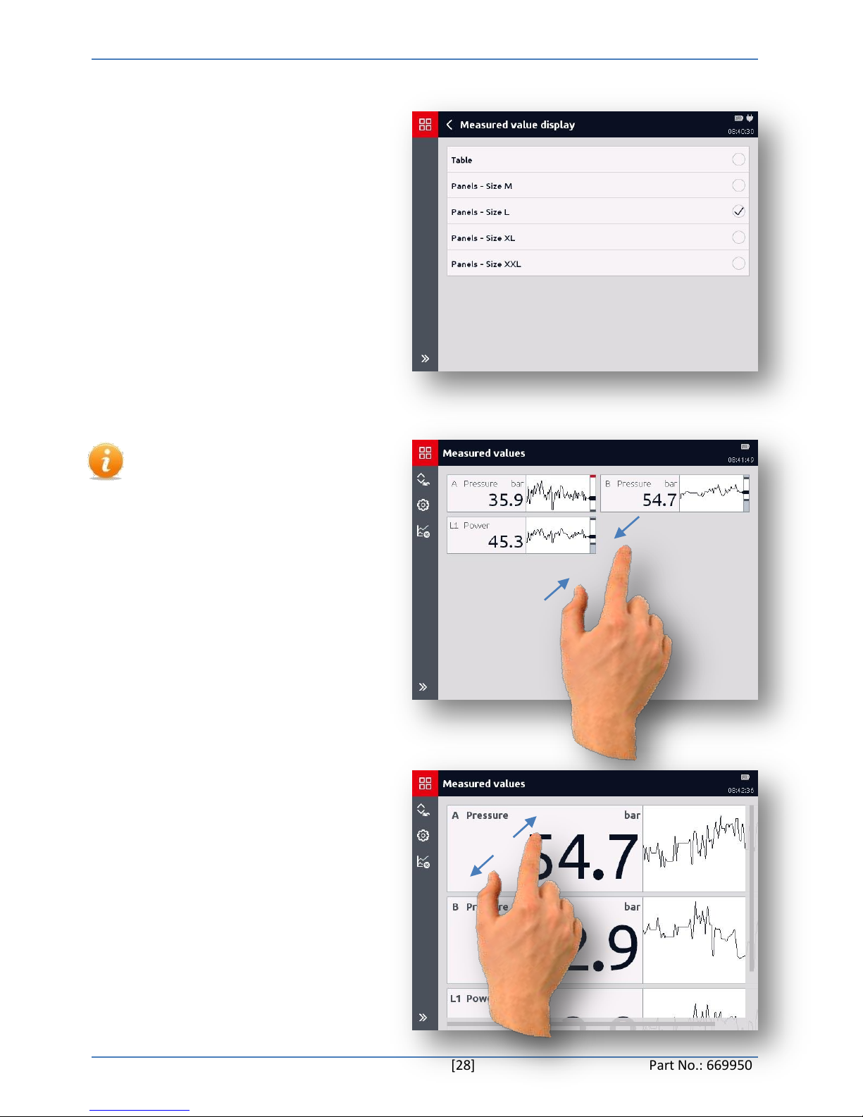
7.2.2 Measured value display
Upon selecting "Measured value
display", a selection list for
displaying the individual measured
values appears:
Table
Panels - Size M
Panels - Size L
Panels - Size XL
Panels - Size XXL
In this menu point, you can
select between measured
value table and different
numerical display fields for
display size of the individual
measured values.
Alternatively, you can increase
or decrease the size of the
display fields directly via the
touchscreen by using your
fingers to enlarge and shrink.
Measured values HMG 4000
Edition 2016-03-08 - V01 R04 [29] Part No.: 669950
7.2.3 Displaying min./max.
values
After selecting "Show min./max.
values", the min. and max. values
will be shown together with the
measured value.
The min./max. values will continue
to be displayed until either the
display is switched off or the
min./max. values are reset in the
meantime by the button.
7.2.4 Displaying bars
With the "Show bars" selection, you
also switch on a bar display in the
measured value display.
The appearance of the display may
vary according to what settings
have been made for rendering the
measured values.
Measured values HMG 4000
Edition 2016-03-08 - V01 R04 [30] Part No.: 669950
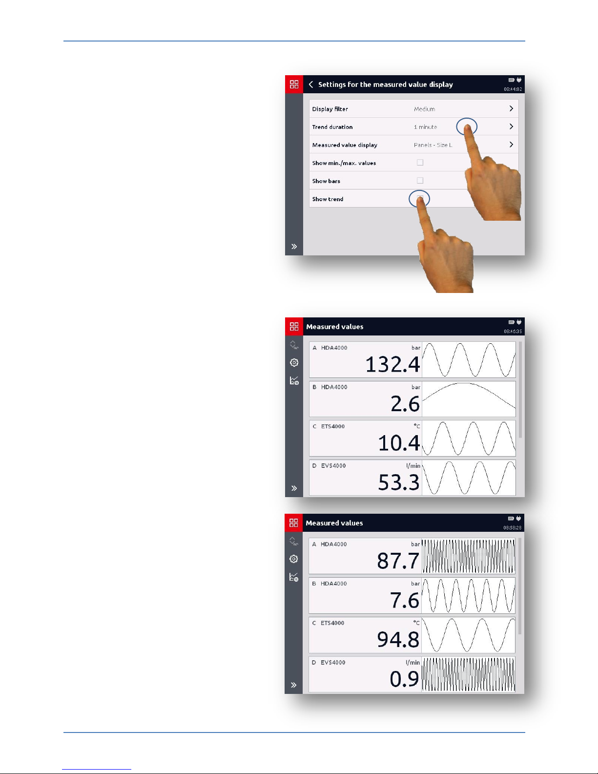
7.2.5 Displaying trend
With the "Show trend" selection,
you can also switch the trend
display on and off in the measured
value display.
You can select for which period the
history should be shown.
You can choose from different time
periods from 10 seconds to 60
minutes.
Different display images appear in
the measured value display
depending on the trend display
settings.
 Loading...