

Page 1
ProtokollBeschreibung
Protocol Description
CANopen
HIT 1000 / HIT 1500
(Originalanleitung /
(Translation of original instructions)
Mat Nr..: 669962 Stand: 17.11.2016 D / E
Page 2

Protokoll-Beschreibung CANopen HIT 1000 / 1500 Seite 2
Inhaltsverzeichnis
1 Einleitung ...................................................................................................................... 6
2 Funktionen des HIT 1000 / 1500 CANopen ................................................................. 6
3 Übertragungsraten ....................................................................................................... 7
4 CAN-Frames ................................................................................................................. 7
5 Node-ID ....................................................................................................................... .. 7
6 Übertragungsdienste ................................................................................................... 7
6.1 Service Data Object (SDO) ......................................................................................... 7
6.2 Process Data Object (PDO) ........................................................................................ 8
6.3 Synchronisation Object (S Y NC) .................................................................................. 9
6.4 Emergency Object (EMCY) ........................................................................................10
6.5 Heartbeat ...................................................................................................................10
6.6 Network Management Services (NMT) ......................................................................11
6.7 Boot Up Protocol ........................................................................................................11
7 Datenfluss im HIT 1000 / 1500 CANopen ...................................................................12
7.1 Sensor Unit ................................................................................................................12
7.2 Calibration & Scaling .................................................................................................12
7.3 Filter & Fusion ...........................................................................................................12
7.4 Transmission Unit ......................................................................................................12
8 Das Object Dictionary .................................................................................................13
8.1 Aufbau des Object Dictionary .....................................................................................13
8.2 Struktur des gerätespezifischen Teils nach DS410 ....................................................13
9 Einträge im Object Dictionary ....................................................................................14
9.1 Communication Profile Specific Entries (DS301) .......................................................14
9.1.1 Index 1000h: DeviceType (read only) ................................................................. 14
9.1.2 Index 1001h: ErrorRegister (read only) ............................................................... 14
9.1.3 Index 1003h: Pre-defined error field (read only) .................................................. 14
9.1.4 Index 1005h: SyncMessageIdentifier (read write) ............................................... 14
9.1.5 Index 1008h: ManufacturerDeviceName (const) ................................................. 14
9.1.6 Index 1009h: ManufacturerHardwareVersion (const) .......................................... 14
9.1.7 Index 100Ah: ManufacturerSoftwareVersion (const) ........................................... 14
9.1.8 Index 1010h: StoreParameters ........................................................................... 14
9.1.9 Index 1011h: RestoreDefaultParameters ............................................................ 15
9.1.10Index 1014h: CobIdEmergencyMessage (read write) ......................................... 15
9.1.11Index 1017h: ProducerHeartbeatTime (read write) ............................................. 15
9.1.12Index 1018h: IdentityObject ................................................................................ 16
9.1.13Index 1029h: Error behaviour ............................................................................. 16
9.1.14Index 1800h / 1801h / 1802h / 1803h: TPDO communication parameter ............ 16
Stand 17.11.2016 HYDAC ELECTRONIC GMBH Mat.-Nr.: 669962
Page 3

Protokoll-Beschreibung CANopen HIT 1000 / 1500 Seite 3
9.1.15Index 1A00h / 1A01h / 1A02h / 1A03h: TPDO mapping parameter ..................... 17
9.1.16Index 1F80h: NMT-Startup (read / write) ............................................................. 18
9.2 Device Profile Specific Entries (DS410) .....................................................................18
9.2.1 Index 6000h: Resolution (read only) ................................................................... 18
9.2.2 Index 6010h: Slope long16 (read only) Statische Neigung .................................. 19
9.2.3 Index 6011h: Slope long16 operating parameter (read write) .............................. 19
9.2.4 Index 6020h: Slope lateral16 (read only) Statische Neigung ............................... 19
9.2.5 Index 6021h: Slope lateral16 operating parameter (read write) ........................... 19
9.3 Manufacturer Specific Entries ....................................................................................19
9.3.1 Index 2001h: NodeID .......................................................................................... 19
9.3.2 Index 2002h: Baudrate ....................................................................................... 19
9.3.3 Index 5130h: Skalierte Beschleunigungswerte .................................................... 20
9.3.4 Index 5131h: Skalierte Drehratenwerte ............................................................... 20
9.3.5 Index 5132h: Neigung im Raum (bewegungskompensiert) ................................. 20
9.3.6 Index 5000h: Status der Neigungsmessung ........................................................ 21
9.3.7
Weitere Indizes im Bereich 2000h bis 5FFFh (reserved) ..................................... 21
10 Layer setting services (LSS) und Protokolle .............................................................22
10.1Finite state automaton, FSA.......................................................................................23
10.2Übertragung von LSS-Diensten .................................................................................24
10.2.1LSS-Nachrichtenformat....................................................................................... 24
10.3Switch mode Protokolle .............................................................................................25
10.3.1Switch mode global Protokoll .............................................................................. 25
10.3.2Switch mode selective Protokoll .......................................................................... 25
10.4Configuration Protokolle .............................................................................................26
10.4.1Configure Node-Id Protokoll ................................................................................ 26
10.4.2Configure bit timing parameters Protokoll ........................................................... 26
10.4.3Activate bit timing parameters Protokoll .............................................................. 27
10.4.4Store configuration Protokoll ............................................................................... 28
10.5Inquire LSS-Address Protokolle .................................................................................28
10.5.1Inquire Identity Vendor-ID Protokoll .................................................................... 28
10.5.2Inquire Identity Product-Code Protokoll ............................................................... 29
10.5.3Inquire Identity Revision-Number Protokoll ......................................................... 29
10.5.4Inquire Identity Serial-Number Protokoll .............................................................. 30
10.5.5Inquire Node-ID Protokoll .................................................................................... 30
10.6Identification Protokolle ..............................................................................................31
10.6.1LSS identify remote slave Protokoll..................................................................... 31
10.6.2LSS identify slave Protokoll ................................................................................ 32
10.6.3LSS identify non-configured remote slave Protokoll ............................................ 32
10.6.4LSS identify non-configured slave Protokoll ........................................................ 32
11 Anschluss ....................................................................................................................33
11.1Einschalten der Versorgungsspannung .....................................................................33
11.2Einstellen der Node-ID und Baudrate mittels LSS-Dienste .........................................33
11.2.1Konfiguration der Node-ID, Ablauf ...................................................................... 33
11.2.2Konfiguration der Baudrate, Ablauf ..................................................................... 34
Stand 17.11.2016 HYDAC ELECTRONIC GMBH Mat.-Nr.: 669962
Page 4

Protokoll-Beschreibung CANopen HIT 1000 / 1500 Seite 4
12 Inbetriebna h me ...........................................................................................................35
12.1CAN – Schnittstelle ....................................................................................................35
12.2EDS-Datei ..................................................................................................................35
Stand 17.11.2016 HYDAC ELECTRONIC GMBH Mat.-Nr.: 669962
Page 5

Protokoll-Beschreibung CANopen HIT 1000 / 1500 Seite 5
Vorwort
Für Sie, den Benutzer unseres Produktes, haben wir in dieser
Dokumentation die wichtigsten Hinweise zum Bedienen und Warten
zusammengestellt.
Sie dient Ihnen dazu, das Produkt kennen zu lernen und seine
bestimmungsgemäßen Einsatzmöglichkeiten optimal zu nutzen.
Diese Dokumentation muss ständig am Einsatzort verfügbar sein.
Bitte beachten Sie, dass die in dieser Dokumentation gemachten Angaben
der Softwaretechnik zu dem Zeitpunkt der Literaturerstellung entsprechen.
Entdecken Sie beim Lesen dieser Dokumentation Fehler oder haben
weitere Anregungen und Hinweise, so wenden Sie sich bitte an:
HYDAC ELECTRONIC GMBH
Technische Dokumentation
Hauptstraße 27
66128 Saarbrücken
-DeutschlandTel: +49(0)6897 / 509-01
Fax: +49(0)6897 / 509-1726
Email: [email protected]
Die Redaktion freut sich über Ihre Mitarbeit.
„Aus der Praxis für die Praxis“
Stand 17.11.2016 HYDAC ELECTRONIC GMBH Mat.-Nr.: 669962
Page 6

Protokoll-Beschreibung CANopen HIT 1000 / 1500 Seite 6
1 Einleitung
Die Neigungsgeber der Familie HIT 1000 / 1500 CANopen entsprechen dem CANopen
Standard gemäß folgenden Profilen und Standards:
[1] CiA DS301, Version: 4.2.0 (21 February 2011)
CANopen application layer and communication profile
[2] CiA DS302, Version: 4.1 (02 February 2009)
Additional application layer functions - Part 2: Network management
[3] CiA DS303, Version: 1.4 (14.08.2006)
Additional specification - Part 2: Representation of SI units and prefix
[4] CiA DS305, Version: 2.2 (26 August 2008)
Layer setting services (LSS) and protocols
[5] CiA DS410, Version 1.3.0 (23 February 2010)
Device profile for inclinometer
Dieses Handbuch beschreibt die vom HIT 1000 / 1500 CANopen unterstützten
Funktionen. Dabei werden Grundkenntnisse von CAN und CANopen vorausgesetzt.
Die genaue Funktionsweise ist in den oben genannten Dokumenten beschrieben. Da
diese in Englisch abgefasst sind, werden die in diesem Handbuch beschriebenen
Dinge, zur besseren Zuordnung, mit dem in der Spezifikation genannten englischen
Begriff bezeichnet und kursiv dargestellt.
2 Funktionen des HIT 1000 / 1500 CANopen
• Berechnung der Neigung aus den Beschleunigungskomponenten in 3
Raumachsen mit Tiefpassfunktion bei HIT 1000 und HIT 1500 (statische
Neigungsmessung)
• Berechnung der Neigung durch Fusion von Beschleunigungs- und
Drehratenkomponenten bei HIT 1500 (bewegungskompensierte
Neigungsmessung, hochdynamisch)
• Umrechnung der Neigungswerte in Euler-Winkel (Einheit °, ein- oder
zweiachsig)
• Übertragung der aktuellen Neigungswerte als PDO bei folgenden Ereignissen:
• Synchron über empfangene SYNC-Objekte
• Asynchron zyklisch im Bereich von 5 Millisekunden bis >1 Minute
Stand 17.11.2016 HYDAC ELECTRONIC GMBH Mat.-Nr.: 669962
Page 7

Protokoll-Beschreibung CANopen HIT 1000 / 1500 Seite 7
3 Übertragungsraten
Der HIT 1000 / 1500 CANopen unterstützt folgende Übertragungsraten (Baudraten):
• 1000 kbit/s
• 800 kbit/s
• 500 kbit/s
• 250 kbit/s
• 125 kbit/s
• 50 kbit/s
• 20 kbit/s
• 10 kbit/s
Das Timing entspricht der DS301, Bit rates and timing.
Die verwendete Übertragungsrate ist in einem nicht-flüchtigen Speicher hinterlegt.
Sie ist im Auslieferzustand auf 250 kbit/s eingestellt und kann über den CAN-Bus
geändert werden (Siehe Object Dictionary Index 2002h).
4 CAN-Frames
Der HIT 1000 / 1500 CANopen unterstützt die in der Spezifikation geforderten 11-bit
Standard–Frames mit 11-bit Identifier sowie 29-bit Frames mit 29-bit Identifier.
5 Node-ID
Zum Betrieb des HIT 1000 / 1500 CANopen in einem CANopen-Netzwerk ist es
notwendig, dass eine innerhalb des Netzes einmalige Node-ID eingestellt wird.
Die eingestellte Node-ID ist in einem nicht-flüchtigen Speicher hinterlegt und kann über
den CAN-Bus (siehe Object Dictionary Index 2001h) eingestellt werden.
Im Auslieferzustand ist die Adresse 1 eingestellt.
6 Übertragungsdienste
6.1 Service Data Object (SDO)
Bei CANopen werden alle Daten eines Gerätes (Einstellparameter und Messdaten) in
einem Object Dictionary unter einem definierten Index abgelegt. Verschiedene Einträge
des Object Dictionary werden mit einem Subindex noch weiter untergliedert. Mit den
SDOs können nun andere Netzteilnehmer das Object Dictionary des HIT 1000 / 1500
CANopen auslesen oder beschreiben.
Der HIT 1000 / 1500 CANopen übernimmt dabei die Rolle eines Servers, das Gerät,
das die Daten auslesen oder beschreiben will, die eines Clients.
Zum Transfer von Daten muss der HIT 1000 / 1500 CANopen ein Receive-SDO
besitzen, mit dem er Daten empfängt und ein Transmit-SDO, mit dem er die Daten
sendet. Ablauf des Datentransfers:
Stand 17.11.2016 HYDAC ELECTRONIC GMBH Mat.-Nr.: 669962
Page 8

Protokoll-Beschreibung CANopen HIT 1000 / 1500 Seite 8
Auslesen des Object Dictionary :
1. Ein Gerät (Client) sendet das Receive-SDO des HIT 1000 / 1500 CANopen
(Server).
In diesem SDO befindet eine Kennung, dass das Object Dictionary gelesen werden
soll, sowie der gewünschte Index und Subindex.
2. Der HIT 1000 / 1500 CANopen (Server) sendet sein Transmit-SDO. In diesem
befinden sich ebenfalls der Index und der Subindex, sowie die gelesenen Daten.
Beschreiben des Object Dictionary :
1. Ein Gerät (Client) sendet das Receive-SDO des HIT 1000 / 1500 CANopen
(Server).
In diesem SDO befinden eine Kennung, dass das Object Dictionary beschrieben
werden soll, sowie der gewünschte Index, Subindex und die einzuschreibenden
Daten.
2. Der HIT 1000 / 1500 CANopen (Server) sendet sein Transmit-SDO. In diesem
befinden sich ebenfalls der Index und der Subindex, sowie eine Kennung, dass das
Object Dictionary beschrieben wurde.
Sollte dabei ein Fehler auftreten, z.B. dass der angegebene Index nicht existiert, oder
dass versucht wurde einen read only Eintrag zu beschreiben, oder dass die Daten
nicht innerhalb des Gültigkeitsbereiches lagen, so enthält das Transmit-SDO eine
entsprechende Abort SDO Transfer - Kennung und einen entsprechenden Abort Code
(siehe [1])
Die jeweilige COB-ID des SDO entspricht dem in der DS301 festgelegten Pre defined
Connection Set und ist nicht änderbar.
COB-IDs für Service Data Objects
SDO COB-ID
Receive – SDO 600h+Node-ID
Transmit – SDO 580h+Node-ID
6.2 Process Data Object (PDO)
Die Datenübertragung mittels SDOs ist zwar sehr flexibel, hat aber für die Übertragung
von Messwerten oder Stellgrößen einige Nachteile: Es kann nur ein Datum gelesen
werden, die Daten müssen erst mit einem SDO angefordert werden und dadurch dass
der jeweilige Index und Subindex mit übertragen wird, steigt der so genannte Overhead
weiter.
Aus diesem Grund definiert CANopen so genannte Process Data Objects. Diese
enthalten nur die notwendigen Nutzdaten. Es gibt zwei Arten von PDOs:
1. Transmit-PDOs
Hiermit kann ein Messgerät seine Messwerte senden.
2. Receive-PDOs
Hiermit können einem Stellglied oder einer Regelungseinheit die Stellgrößen
übertragen werden.
Stand 17.11.2016 HYDAC ELECTRONIC GMBH Mat.-Nr.: 669962
Page 9

Protokoll-Beschreibung CANopen HIT 1000 / 1500 Seite 9
Welche Daten sich nun in einem PDO befinden, wird durch das so genannte PDO-
Mapping festgelegt. Dieses PDO-Mapping ist im Object Dictionary hinterlegt (siehe
Object Dictionary, Index 1A00h, 1A01h, 1A02h, 1A03h).
Mit welcher ID und bei welchem Ereignis ein PDO übertragen wird, ist in dem PDOTransmission Type festgelegt. Diese Einstellungen befinden sich ebenfalls im Object
Dictionary hinterlegt (siehe Object Dictionary, Index 1800h, 1801h, 1802h, 1803h).
Ereignisse, die zum Senden eines PDOs führen:
1. Empfang eines SYNC Objektes (Synchroner Transfer).
2. Ablauf einer einstellbaren Zykluszeit im Bereich von 5 Millisekunden bis >1 Minute
(Zyklischer Transfer).
Der HIT 1000 / 1500 CANopen implementiert mehrere Transmit-PDO, welche die
aktuellen Sensor- bzw. Prozesswerte beinhalten.
Die DS410 sieht als Standardeinstellung die Übertragung der aktuellen Messwerte als
16-bit oder 32-bit Wert vor.
Der HIT 1000 / 1500 CANopen implementiert nur die Übertragung als 16-bit Wert.
6.3 Synchronisation Object (SYNC)
SYNC Objekte dienen zur Realisierung eines synchronen Datentransfers. Ein SYNC
Objekt ist im Prinzip eine CAN Nachricht mit einem definierten Identifier, ohne Daten.
CANopen unterscheidet zwischen SYNC Producer und SYNC Consumers. SYNC
Producer sind Geräte am Bus, die in einstellbaren Zeitabständen ein SYNC senden.
SYNC Consumers sind Geräte, die auf den Empfang eines SYNC reagieren. In einem
CANopen Netzwerk können mehrere SYNC Objekte existieren. Unterschieden werden
die einzelnen SYNC Objekte anhand der SYNC-ID, welche dem verwendeten CAN
Identifier entspricht. Die verwendete SYNC-ID ist im Object Dictionary hinterlegt.
Der HIT 1000 / 1500 CANopen bietet die Funktionalität eines SYNC Consumers. Bei
entsprechender Einstellung des PDO Transmission Type wird beim Empfang eines
SYNC ein PDO gesendet. Die SYNC-ID ist auf 80h voreingestellt und kann im Object
Dictionary geändert werden (siehe Object Dictionary, Index 1005h). Unter PDO
Transmission Type kann die Anzahl der empfangenen SYNC Objekte, die zum Senden
eines PDO, führt eingestellt werden.
Stand 17.11.2016 HYDAC ELECTRONIC GMBH Mat.-Nr.: 669962
Page 10

Protokoll-Beschreibung CANopen HIT 1000 / 1500 Seite 10
6.4 Emergency Object (EMCY)
EMCY Objekte werden beim Auftreten eines Fehlers gesendet. EMCY Objekte
enthalten einen Emergency Error Code, den Inhalt des Error register sowie ein
Manufacturer specific Error Field. Ist ein gemeldeter Fehler beseitigt oder
verschwunden, so wird dies ebenfalls durch ein spezielles EMCY Objekt gemeldet.
Eine Emergency-Nachricht wird gesendet, wenn ein Fehler auftritt oder dieser Fehler
wieder verschwindet. Die Nachricht ist folgendermaßen aufgebaut:
Fehler Emergency
ErrorCode
Kein Fehler 0000h 0000h
Fehler beim
FF00h 0001h
Laden des
User-Setup
Controllerfehler FF00h 0002h
Manufacturer
SpecificErrorField
Fehler Kategorie
Fehler beseitigt
Herstellerspezifischer
Fehler (Bit 7)
Herstellerspezifischer
Fehler (Bit 7)
Reserviert N/A 0003h N/A
Reserviert N/A 0004h N/A
CAN Error
Passive
Recovered
from Bus-off
8120h 0005h
8140h 0006h
Kommunikationsfehler
(Bit 4)
Kommunikationsfehler
(Bit 4)
Das EMCY Objekt hat die voreingestellte ID 80h+Node-ID und kann im Object
Dictionary geändert werden (siehe Object Dictionary, Index 1014h).
6.5 Heartbeat
Mit dem Heartbeat Protocol kann eine Überwachung der einzelnen Teilnehmer
durchgeführt werden. CANopen unterscheidet zwischen folgenden Funktionen:
1. Heartbeat Producer
sendet in zyklischen Abständen ein Heartbeat Objekt.
2. Heartbeat Consumer
überwacht das Senden von bestimmten Heartbeat Objekten.
Die Zykluszeit ist im Object Dictionary in Millisekunden einstellbar. Eine Zeitangabe
von 0 bedeutet „Heartbeat nicht aktiv“.
Mit dem Heartbeat Objekt wird immer der Status des Heartbeat Producers als Byte mit
übertragen.
Stand 17.11.2016 HYDAC ELECTRONIC GMBH Mat.-Nr.: 669962
Page 11

Protokoll-Beschreibung CANopen HIT 1000 / 1500 Seite 11
A
Bedeutung des Heartbeat- Objektinhaltes
Wert Status
nmerkung
0 BOOTUP Das Gerät hat gebootet.
4 STOPPED Das Gerät ist gestoppt.
5 OPERATIONAL Das Gerät arbeitet normal.
127 PRE-OPERATIONAL Das Gerät sendet keine PDOs, kann aber SDOs
bearbeiten.
Der HIT 1000 / 1500 CANopen kann als Heartbeat Producer arbeiten. Die ID des
Heartbeat ist 700h + Node-ID. Die Zeit ist mit 0 (nicht aktiv) voreingestellt und kann
geändert werden (siehe Object Dictionary, Index 1017h).
6.6 Network Management Services (NMT)
NMT Objekte dienen dazu Geräte zu starten, zu stoppen oder zurückzusetzen.
CANopen unterscheidet zwischen folgenden Funktionalitäten:
1. NMT Master
steuert andere Knoten.
2. NMT Slave
wird von einem Master gesteuert.
In einem CANopen Netzwerk existiert nur ein NMT Objekt mit dem Identifier 0. Es
werden immer 2 Bytes übertragen. Das erste Byte enthält den Command Specifier, der
den Befehl repräsentiert, das zweite Byte enthält die Node-ID des Knotens, der diesen
Befehl ausführen soll. Ein Wert von 0 bedeutet, dass dieser Befehl für alle Knoten gilt.
Folgende Befehle sind möglich:
NMT Befehle
1. Start Remote Node
Der Knoten wechselt in den Zustand Operational.
2. Stop Remote Node
Der Knoten wechselt in den Zustand Stopped.
3. Enter Pre-Operational
Der Knoten wechselt in den Zustand Pre-Operational.
4. Reset Node
Der "Device Profile Specific"-OD-Bereich wird zurückgesetzt, die Baudrate wird
gegebenenfalls neu initialisiert und wechselt dann in den Zustand Reset
Communication.
5. Reset Communicatiuon
Die Kommunikationseinheit des Knotens wird zurückgesetzt und danach
wechselt der Knoten in den Zustand Pre-Operational.
Der HIT 1000 / 1500 CANopen arbeitet als NMT Slave und unterstützt alle NMT
Dienste.
6.7 Boot Up Protocol
Wenn ein NMT Slave nach der Initialisierung in den Zustand Pre-operational wechselt,
sendet er jeweils ein Boot Up Objekt. Dies ist im Prinzip nichts anders als ein
Heartbeat Objekt mit dem Status 0.
Beim HIT 1000 / 1500 CANopen ist diese Funktion realisiert.
Stand 17.11.2016 HYDAC ELECTRONIC GMBH Mat.-Nr.: 669962
Page 12
Protokoll-Beschreibung CANopen HIT 1000 / 1500 Seite 12
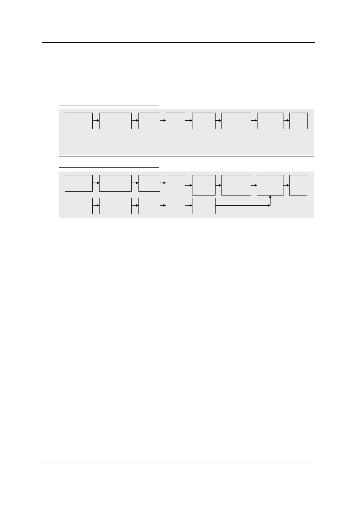
7 Datenfluss im HIT 1000 / 1500 CANopen
Nachfolgende Bilder zeigen den Datenfluss innerhalb des HIT 1000 / 1500 CANopen,
sowie die jeweiligen Indizes des Object Dictionary.
Datenfluss im HIT 1000 CANopen
Acceleration
Sensor
3D
Calibration
Scaling
T-Compensation
Field Value
5130h
Filter
Operating
Parameters
6011h/6021h
Process Values
6010h
6020h
Transmission
Unit
CAN
Message
Datenfluss im HIT 1500 CANopen
Acceleration
Sensor
Turn Rate
Sensor
3D
3D
Calibration
Scaling
T-Compensation
Calibration
Scaling
T-Compensation
Field Value
5130h
Field Value
5131h
Filter
&
Fusion
Operating
Parameters
6011h
6021h
Process
Value
5132h
Process Values
6010h
6020h
Transmission
Unit
CAN
Message
7.1 Sensor Unit
Die Sensoreinheit erfasst die Neigung gegen die Horizontale und die Drehrate. Die
Messwerte werden in digitaler Form bereitgestellt.
Der Typ der Sensoreinheit (Inclination Transducer) ist in Sensor Type hinterlegt.
7.2 Calibration & Scaling
Die Sensorwerte werden in Calibration & Scaling aufbereitet und stehen als FieldValue
zur Verfügung.
7.3 Filter & Fusion
Die kalibrierten Sensorwerte werden in Filter & Fusion gefiltert (HIT 1000 und HIT1500)
und fusioniert (nur HIT 1500) und stehen nach der Operating Parameters Einheit als
ProcessValue zur Verfügung.
7.4 Transmission Unit
Tritt eines der folgenden Ereignisse ein, so wird in Abhängigkeit des eingestellten
TransmissionType der Wert des PDO gesendet.
1. Der EventTimer ist abgelaufen (zyklische Übertragung).
2. Ein oder mehrere Sync Objekte wurden empfangen (synchrone Übertragung).
Stand 17.11.2016 HYDAC ELECTRONIC GMBH Mat.-Nr.: 669962
Page 13

Protokoll-Beschreibung CANopen HIT 1000 / 1500 Seite 13
8 Das Object Dictionary
8.1 Aufbau des Object Dictionary
Im Object Dictionary sind, wie bereits mehrfach erwähnt, alle Daten hinterlegt. In den
folgenden Kapiteln sind die vom HIT 1000 / 1500 CANopen unterstützten Einträge
aufgeführt. Die Angabe des Index erfolgt spezifikationsgemäß immer in hexadezimaler
Notation, ohne dass die hexadezimale Darstellung extra angezeigt wird. Bei jedem
Eintrag ist auch die Zugriffsart angegeben. CANopen unterscheidet dabei folgende
Zugriffsarten:
Zugriffsarten (Acces Type) für das Object Dictionary
1. const
Kann nur gelesen werden und liefert immer den gleichen Wert.
2. read only
Kann nur gelesen werden, der Wert kann sich aber während des Betriebes ändern.
3. write only
Der Eintrag kann nur geschrieben werden.
4. read write
Der Eintrag kann geschrieben und gelesen werden.
CANopen unterscheidet innerhalb des Data Dictionary folgende Bereiche:
Bereiche des Object Dictionary:
1. Index 0000h .. 1FFFh: Communication profile specific entries
Einstellungen, die für alle CANopen-Geräte gelten. Diese Einträge sind in der
DS301 und DS302 festgelegt.
2. Index 6000h .. 9FFFh: Device profile specific entries
Gerätespezifische Daten, die in einer Draft Standard festgelegt sind.
Der HIT 1000 / 1500 CANopen hat das Geräteprofil DS410 realisiert.
3. Index 2000h .. 5FFFh: Manufacturer specific entries
Herstellerspezifische zusätzliche Daten, die in keiner Spezifikation festgelegt sind.
8.2 Struktur des gerätespezifischen Teils nach DS410
Der HIT 1000 / 1500 CANopen implementiert die DS410. Diese beschreibt das
Verhalten und die Funktionalität von Neigungsgebern (inclinometer).
Stand 17.11.2016 HYDAC ELECTRONIC GMBH Mat.-Nr.: 669962
Page 14

Protokoll-Beschreibung CANopen HIT 1000 / 1500 Seite 14
9 Einträge im Object Dictionary
Im Folgenden sind die vom HIT 1000 / 1500 CANopen realisierten Funktionalitäten
aufgezeigt. Eine detaillierte Beschreibung der Einträge kann in [1] und [5] nachgelesen
werden.
9.1 Communication Profile Specific Entries (DS301)
9.1.1 Index 1000h: DeviceType (read only)
Enthält die Nummer des verwendeten Geräteprofiles, hier die Nummer 410, sowie die
profilspezifische Erweiterung, hier eine 2, für die Unterstützung von 2 Achsen mit 16Bit
maximaler Auflösung.
9.1.2 Index 1001h: ErrorRegister (read only)
Enthält den aktuellen Fehlerzustand (siehe EMCY, sowie [1]).
9.1.3 Index 1003h: Pre-defined error field (read only)
Hier werden die Fehler bereitgestellt, die im CANopen Gerät aufgetreten sind, und
mittels emergency object signalisiert wurden (siehe CiA 301)
9.1.4 Index 1005h: S yncMessageIdentifier (read write)
Hier kann die COB-ID für das SYNC-Objekt eingestellt werden.
9.1.5 Index 1008h: ManufacturerDeviceName (const)
Liefert den Gerätenamen als Zeichenkette. („HIT1000“).
9.1.6 Index 1009 h: ManufacturerHardwareVersion (const)
Liefert die Hardwareversion als Zeichenkette (z.B. „01.03“).
9.1.7 Index 100Ah: ManufacturerSoftwa reVersion (const)
Liefert die Softwareversion als Zeichenkette (z.B. „03.02“). Die beiden ersten Zeichen
bezeichnen die Version, die letzten beiden Zeichen den Revisionsstand.
9.1.8 Index 1010h: StoreParameters
Durch Einschreiben der Zeichenkette „save“ (65766173h) werden die aktuellen
Einstellungen in den nicht flüchtigen Speicher übertragen.
Der HIT 1000 / 1500 CANopen speichert Einstellungen nicht automatisch wenn sie
geändert werden, sondern nur auf Anforderung.
ACHTUNG: Geänderte Einstellungen müssen mit StoreParameters explizit
gesichert werden, sonst gehen sie beim Abschalten des Gerätes oder bei den
NMT-Befehlen Reset Node und Reset Communication verlor en.
Stand 17.11.2016 HYDAC ELECTRONIC GMBH Mat.-Nr.: 669962
Page 15

Protokoll-Beschreibung CANopen HIT 1000 / 1500 Seite 15
CANopen bietet die Möglichkeit mit Hilfe verschiedener Subindizes verschiedene
Parameterbereiche zu sichern.
Unterstützt wird hier Subindex 1, 2, 3 und 4.
Nähere Informationen sind [1] zu entnehmen.
Achtung: Die Einstellungen der Baudrate und der NodeID bleiben bei
StoreAllParameters erhalten.
Verwendete Subindizes:
0: LargestSubindexSupported (read only)
1: StoreAllParameters (read write)
2: StoreCommunicationParamters (read write) (index von 1000h to 1FFFh)
3: StoreApplicationParamteres (read write) (index von 6000h to 9FFFh)
4: StoreLssParameters (read write) (index von 2000h to 20FFh)
9.1.9 Index 1011h: RestoreDefaultParame ters
Durch Einschreiben der Zeichenkette „load“ (64616F6Ch) werden die werksseitigen
Voreinstellungen in den nicht flüchtigen Speicher übertragen.
Der HIT 1000 / 1500 CANopen arbeitet allerdings bis zum Abschalten oder bis zur
Ausführung der Befehle Reset Node und Reset Communication noch mit den aktuellen
Einstellungen weiter.
CANopen bietet die Möglichkeit mit Hilfe verschiedener Subindizes verschiedene
Parameterbereiche zu restaurieren.
Unterstützt wird hier Subindex 1, 2, 3 und 4.
Nähere Informationen sind [1] zu entnehmen.
Achtung: Die Einstellungen der Baudrate und der NodeID bleiben bei
RestoreAllParameters erhalten.
Verwendete Subindizes:
0: LargestSubindexSupported (read only)
1: RestoreAllParameters (read write)
2: RestoreCommunicationParamters (read write) (index von 1000h to 1FFFh)
3: RestoreApplicationParamteres (read write) (index von 6000h to 9FFFh)
4: RestoreLssParameters (read write) (index von 2000h to 20FFh)
9.1.10 Index 1014h: CobIdEmergencyMessage (read write)
Hier kann die COB-ID für das EMCY-Objekt eingestellt werden (siehe EMCY).
9.1.11 Index 1017h: ProducerHeartbeatTime (read write)
Hier kann die Heartbeat - Zeit in Millisekunden eingestellt werden. Der Wert 0
bedeutet, dass diese Funktion nicht aktiv ist (siehe Heartbeat).
Stand 17.11.2016 HYDAC ELECTRONIC GMBH Mat.-Nr.: 669962
Page 16

Protokoll-Beschreibung CANopen HIT 1000 / 1500 Seite 16
9.1.12 Index 1018h: IdentityObject
Das Identity Objekt identifiziert den HIT 1000 / 1500 CANopen. Die Identifikation
besteht aus vier 32bit-Zahlen. Die Kombination dieser 4 Zahlen ergibt eine weltweit
eindeutige Identifikation eines Gerätes.
Verwendete Subindizes:
0: LargestSubindexSupported (read only)
1: VendorID (read only)
Eindeutiger Herstellercode (DAh für HYDAC ELECTRONIC GmbH)
2: ProductCode (read only)
Produktcode der Hydac Electronic (z.B: 924854)
3: RevisionNumber (read only)
Revisionsnummer des Gerätes.
4: SerialNumber (read only)
Seriennummer des Gerätes
9.1.13 Index 1029h: Error behaviour
Verwendete Subindizes:
0: Nr of Error Classes (read ony)
1: Communication Error (read write)
0 : Change to NMT state Pre-operational
1 : No change of the NMT state
2 : Change to NMT state Stopped
2: Specific Error Class (read write)
0 : Change to NMT state Pre-operational
1 : No change of the NMT state
2 : Change to NMT state Stopped
9.1.14 Index 1800h / 1801h / 1802h / 1803h: TPDO communication
parameter
Diese Einträge legen die PDO-Übertragung fest. Im Einzelnen sind dies:
Parameter zur PDO-Übertragung
1. COB-ID
Legt den Identifier für das PDO fest. Das höchstwertigste Bit (Bit31) des Eintrages
gehört nicht mehr zur ID und hat die Bedeutung „disable PDO“. Ist dieses Bit
gesetzt, so ist die Übertragung des PDO gesperrt.
2. Transmission Type
Legt den Übertragungstyp fest.
Werte zwischen 0 und 240 bedeuten eine synchrone Übertragung. Die Zahl steht
für die Anzahl der SYNC Objekte, die empfangen werden müssen, bis das PDO
gesendet wird.
Der Wert 254 bedeutet eine herstellerspezifische Übertragung und der Wert 255
eine geräteprofilspezifische Übertragung. Bei 254 und 255 wird das PDO zyklisch
gesendet, sofern eine Zeit (Event Time) ungleich 0 eingestellt ist.
3. Inhibit Time
Dieser Wert legt das minimale Intervall für die PDO Übertragung fest, wenn als
transmission type FEh and FFh gewählt wurde. Der Wert ist als Vielfaches von
100µs definiert. Der Wert 0 schaltet die inhibit time ab.
4. Reserved – ohne Bedeutung
Stand 17.11.2016 HYDAC ELECTRONIC GMBH Mat.-Nr.: 669962
Page 17

Protokoll-Beschreibung CANopen HIT 1000 / 1500 Seite 17
5. Event Time
Legt die Zykluszeit für asynchrone Übertragungen bei Transmission Type 254 und
255 in Millisekunden fest. Der Wert 0 bedeutet keine zeitgesteuerte Übertragung.
Verwendete Subindizes:
0: LargestSubindexSupported (read only)
1: COBIDUsedByPDO (read write)
2: TransmissionType (read write)
3: InhibitTime (read write)
4: Reserved
5: EventTimer(read write)
9.1.15 Index 1A00h / 1A01h / 1A02h / 1A03h: TPDO mapping parameter
Mit diesen Einträgen wird festgelegt, welche Daten mit dem PDO übertragen werden.
Subindex 0 gibt die Anzahl der Daten im PDO an. Unter Subindex 1 ist der Index und
Subindex sowie die Anzahl der Bits des ersten Datums hinterlegt, entsprechendes gilt
für die Subindizes 2 bis 8.
Im Auslieferzustand hat der HIT 1000 / 1500 CANopen folgende Einträge:
Index 1A00h Statische Neigung (HIT 1000 und HIT1500)
Subindex Inhalt Bedeutung
0 3 Drei Werte werden im PDO übertragen.
1 60100010h Der erste Wert im PDO ist der Wert von Index 6010h,
Subindex 0 mit einer Breite von 10h (=16 bit)
2 60200010h Der zweite Wert im PDO ist der Wert von Index 6020h,
Subindex 0 mit einer Breite von 10h (=16 bit)
3 50000008h Der dritte Wert im PDO ist der Status der
Neigungsmessung
Index 1A01h Skalierte Beschleunigungswerte (HIT 1000 und HIT1500)
Subindex Inhalt Bedeutung
0 3 Drei Werte werden im PDO übertragen.
1 51300110h Der erste Wert im PDO ist der Wert von Index 5130h,
Subindex 1 mit einer Breite von 10h (=16 bit)
2 51300210h Der zweite Wert im PDO ist der Wert von Index 5130h,
Subindex 2 mit einer Breite von 10h (=16 bit)
3 51300310h Der dritte Wert im PDO ist der Wert von Index 5130h,
Subindex 3 mit einer Breite von 10h (=16 bit)
Index 1A02h Skalierte Drehratenwerte (nur HIT 1500)
Subindex Inhalt Bedeutung
0 3 Drei Werte werden im PDO übertragen.
1 51310110h Der erste Wert im PDO ist der Wert von Index 5131h,
Subindex 1 mit einer Breite von 10h (=16 bit)
2 51310210h Der zweite Wert im PDO ist der Wert von Index 5131h,
Subindex 2 mit einer Breite von 10h (=16 bit)
3 51310310h Der dritte Wert im PDO ist der Wert von Index 5131h,
Subindex 3 mit einer Breite von 10h (=16 bit)
Stand 17.11.2016 HYDAC ELECTRONIC GMBH Mat.-Nr.: 669962
Page 18

Protokoll-Beschreibung CANopen HIT 1000 / 1500 Seite 18
Index 1A03h Neigung bewegungskompensiert (nur HIT 1500)
Subindex Inhalt Bedeutung
0 2 Zwei Werte werden im PDO übertragen.
1 51320110h Der erste Wert im PDO ist der Wert von Index 5132h,
Subindex 1 mit einer Breite von 10h (=16 bit)
2 51320210h Der zweite Wert im PDO ist der Wert von Index 5132h,
Subindex 2 mit einer Breite von 10h (=16 bit)
Verwendete Subindizes:
0: NumberOfMappedApplicationObjectsInPDO (read write)
Es sind die Werte 0 bis 8 zulässig.
Entsprechend wird kein PDO übertragen, oder ein PDO mit bis zu 8 Werten.
ObjectToBeMapped (1 bis 8) (read write)
Beim HIT 1000 / 1500 CANopen folgende Werte zulässig:
10010008h = Error Register 8bit-Breite
10020020h = Manufacturer Status Register 32bit-Breite
50000008h = Status Neigung 8bit-Breite
51300110h = Prozesswert Beschleunigung in Richtung der X-Achse (siehe 9.3.3)
51300210h = Prozesswert Beschleunigung in Richtung der Y-Achse
51300310h = Prozesswert Beschleunigung in Richtung der Z-Achse
51310110h = Prozesswert Drehrate um die X-Achse (siehe 9.3.4)
51310210h = Prozesswert Drehrate um die Y-Achse
51310310h = Prozesswert Drehrate um die Z-Achse
51320110h = Prozesswert kompensierte Neigung (wie Slope long16 s.u.)
51320210h = Prozesswert kompensierte Neigung (wie Slope lateral16 s.u.)
60100010h = Prozesswert Slope long16 mit 16bit-Breite (DS410 vgl. [5])
60200010h = Prozesswert Slope lateral16 mit 16bit-Breite (DS410 vgl. [5])
9.1.16 Index 1F80h: NMT-Startup (read / write)
Wird Bit 2 gesetzt, so wird automatisch bei Erreichen des „Pre-Operational“ Status in
den „Operational“ Status gewechselt (DS302).
Erlaubte Werte sind: 08h und 0Ch
9.2 Device Profile Specific Entries (DS410)
9.2.1 Index 6000h: Resolution (read only)
Dieser Eintrag enthält die Auflösung der Neigungswerte in Winkelgrad.
Der HIT 1000 / 1500 CANopen liefert den Wert 0Ah zurück.
Gemäß DS410 entspricht das einer Auflösung von 0,01° (siehe [5]).
Stand 17.11.2016 HYDAC ELECTRONIC GMBH Mat.-Nr.: 669962
Page 19

Protokoll-Beschreibung CANopen HIT 1000 / 1500 Seite 19
–
9.2.2 Index 6010h: Slope long16 (read only) Statische Neigung
Dieser Eintrag enthält die Neigung in longitudinaler Richtung als vorzeichenbehafteter
16Bit Wert (siehe [5]).
9.2.3 Index 6011h: Slope long16 operating parameter (read write)
Dieser Eintrag enthält die Informationen zur Interpretation des Messwerts
SlopeLong16.
Der HIT 1000 / 1500 CANopen liefert standardmäßig den Wert 00h zurück (siehe [5]).
Bit 7
1 Bit 0 Funktion
0 0
0 1
Invertierung aus
Invertierung ein
9.2.4 Index 6020h: Slope lateral16 (read only) Statische Neigung
Dieser Eintrag enthält die Neigung in lateraler Richtung als vorzeichenbehafteter 16Bit
Wert (siehe [5] – nur bei zweiachsigen Geräten)
9.2.5 Index 6021h: Slope lateral16 operating parameter (read write)
Dieser Eintrag enthält die Informationen zur Interpretation des Messwerts
SlopeLateral16 (siehe 9.2.3).
Der HIT 1000 / 1500 CANopen liefert standardmäßig den Wert 00h zurück (siehe [5]).
9.3 Manufacturer Specific Entries
9.3.1 Index 2001 h: NodeID
Unter diesem Index ist die Node-ID hinterlegt.
Verwendete Subindizes:
0: NumberOfEntries (read only)
1: CurrentNodeId (read only)
2: DemandedNodeId (read write)
Damit die neue NodeId wirksam wird, muss erst der Befehl StoreLssParameters
übertragen werden und danach der Knoten neu gestartet werden.
9.3.2 Index 2002h: Baudrate
Unter diesem Index ist die Baudrate hinterlegt.
Die Zuordnung des Eintrages zu der Baudrate entspricht der DS305, Layer Setting
Services and Protocols.
Eintrag 0 1 2 3 4 5 6 7 8
Baudrate
1000
kbit/s
800
kbit/s
500
kbit/s
250
kbit/s
125
kbit/s
reserved
50
kbit/s
Damit die neue Baudrate wirksam wird, muss erst der Befehl StoreLssParameters
übertragen werden und danach der Knoten neu gestartet werden.
20
kbit/s
10
kbit/s
Stand 17.11.2016 HYDAC ELECTRONIC GMBH Mat.-Nr.: 669962
Page 20

Protokoll-Beschreibung CANopen HIT 1000 / 1500 Seite 20
Verwendete Subindizes:
0: NumberOfEntries (read only)
1: CurrentBaudrate (read only)
2: DemandedBaudrate (read write)
9.3.3 Index 5130h: Skalierte Beschleunigungswerte
Unter diesem Index ist der aktuelle Prozesswert für die Komponente der
Erdbeschleunigung in Richtung der X, Y und Z-Achse des Neigungsgebers
hinterlegt.
Die Werte sind in 1/100 m/s
Der Prozesswert 981 entspricht 9,81 m/s
2
skaliert.
2
= 1g.
Verwendete Subindizes:
0: NumberOfEntries (read only)
1: X-Komponente Int16 (read only)
2: Y-Komponente Int16 (read only)
3: Z-Komponente Int16 (read only)
9.3.4 Index 5131h: Skalierte Drehratenwerte
Unter diesem Index ist der aktuelle Prozesswert für die Drehrate um die X, Y und ZAchse des Neigungsgebers hinterlegt (im Bogenmaß).
Die Werte sind in 0,2 Millirad/s skaliert. 2 π/s entspricht einer Umdrehung/s.
Ein Prozesswert von 15000 entspricht demnach einer Drehrate von 3 rad/s.
Verwendete Subindizes:
0: NumberOfEntries (read only)
1: X-Komponente Int16 (read only)
2: Y-Komponente Int16 (read only)
3: Z-Komponente Int16 (read only)
Die nachfolgende Zeichnung zeigt den positiven Drehsinn um eine gedachte Achse
9.3.5 Index 5132h: Neigung im Raum (bewegungskompensiert)
Unter diesem Index ist der aktuelle Prozesswert für die kompensierte Neigung gegen
die Horizontale in X, Y und Z hinterlegt.
Der Wert hat eine Auflösung von 0,01° (vgl. Index 6010h / 6020h)
Verwendete Subindizes:
0: NumberOfEntries (read only)
1: Entsprechend Slope long16 Komponente Int16 (read only)
2: Entsprechend Slope lateral16 Komponente Int16 (read only)
Stand 17.11.2016 HYDAC ELECTRONIC GMBH Mat.-Nr.: 669962
Page 21

Protokoll-Beschreibung CANopen HIT 1000 / 1500 Seite 21
–
9.3.6 Index 5000h: Status der Neigungsmessung
Unter diesem Index ist der Status der Neigungsmessung hinterlegt.
Verwendete Subindizes:
0: Status Uint8 (read only)
Die Codierung ist bitweise wie folgt:
Bit 7
Reserviert
Immer 0
3 Bit 2 Bit 1 Bit 0
Schwerer
Fehler
Gerät in
Bewegung
Sensor-Temperatur
außerhalb Regelbereich
9.3.7 Weitere Indizes im Bereich 2000h bis 5FFFh (reserved)
Die Indizes in diesem Bereich enthalten wichtige Werkseinstellungen und dürfen
kundenseitig nicht verändert werden!
Achtung: Jeder Eingriff kann zur Fehlfunktion des Neigungsgebers führen!
Stand 17.11.2016 HYDAC ELECTRONIC GMBH Mat.-Nr.: 669962
Page 22

Protokoll-Beschreibung CANopen HIT 1000 / 1500 Seite 22
10 Layer setting services (LSS) und Protokolle
Die LSS-Dienste und Protokolle, dokumentiert in CiA DS305 V2.2, siehe [4],
unterstützen das Abfragen und Konfigurieren verschiedener Parameter des Data Link
Layers und des Application Layers eines LSS-Slaves durch ein LSS-Master über das
CAN Netzwerk.
Unterstützt werden folgende Parameter:
- Node-ID
- Baudrate
- LSS-Adresse, gemäß dem Identity Objekt 1018h
Der Zugriff auf den LSS-Slave erfolgt dabei über seine LSS-Adresse, bestehend aus:
- Vendor-ID
- Produkt-Code
- Revisions-Nummer und
- Serien-Nummer
Das Mess-System unterstützt folgende Dienste:
Switch mode services
● Switch mode selective
¾ einen bestimmten LSS-Slave ansprechen
● Switch mode global
¾ alle LSS-Slaves ansprechen
Configuration services
● Configure Node-ID
¾ Node-ID konfigurieren
● Configure bit timing parameters
¾ Baudrate konfigurieren
● Activate bit timing parameters
¾ Baudrate aktivieren
● Store configured parameters
¾ konfigurierte Parameter speichern
Inquiry services
● Inquire LSS-address
¾ LSS-Adresse anfragen
● Inquire Node-ID
¾ Node-ID anfragen
Identification services
● LSS identify remote slave
¾ Identifizierung von LSS-Slaves innerhalb eines bestimmten
Bereichs
● LSS identify slave
¾ Rückmeldung der LSS-Slaves auf das vorherige Kommando
● LSS identify non-configured remote slave
¾ Identifizierung von nicht-konfigurierten LSS-Slaves, Node-ID = FFh
● LSS identify non-configured slave
¾ Rückmeldung der LSS-Slaves auf das vorherige Kommando
Stand 17.11.2016 HYDAC ELECTRONIC GMBH Mat.-Nr.: 669962
Page 23
Protokoll-Beschreibung CANopen HIT 1000 / 1500 Seite 23
10.1 Finite state automaton, FSA
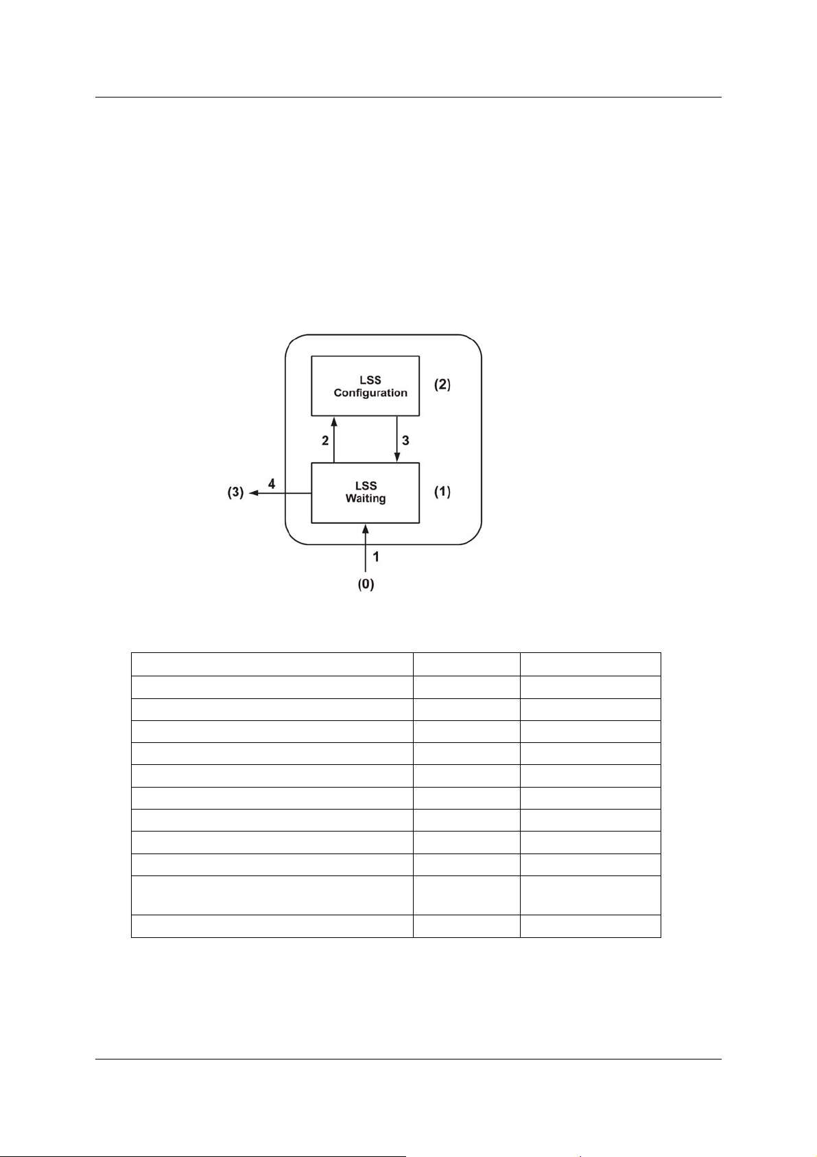
Der FSA entspricht einer Zustandsmaschine und definiert das Verhalten eines LSSSlaves. Gesteuert wird die Zustandsmaschine durch LSS COBs erzeugt durch einen
LSS-Master, oder NMT COBs erzeugt durch einen NMT-Master, oder lokale NMTZustandsübergänge.
Die LSS-Modes unterstützen folgende Zustände:
(0) Initial: Pseudo-Zustand, zeigt die Aktivierung des FSAs an
(1) LSS waiting: Unterstützung aller Dienste wie unten angegeben
(2) LSS configuration: Unterstützung aller Dienste wie unten angegeben
(3) Final: Pseudo-Zustand, zeigt die Deaktivierung des FSAs an
Abbildung 1: LSS-Modes
Zustandsverhalten der unterstützten Dienste
Dienste Waiting Configuration
Switch mode global Ja Ja
Switch mode selective Ja Nein
Activate bit timing parameters Nein Ja
Configure bit timing parameters Nein Ja
Configure Node-Id Nein Ja
Store configuration Nein Ja
Inquire LSS-address Nein Ja
LSS identify remote slave Ja Ja
LSS identify slave Ja Ja
LSS identify non-configured remote
slave
Ja Ja
LSS identify non-configured slave Ja Ja
LSS FSA Zustandsübergänge
Stand 17.11.2016 HYDAC ELECTRONIC GMBH Mat.-Nr.: 669962
Page 24

Protokoll-Beschreibung CANopen HIT 1000 / 1500 Seite 24
Übergang Ereignisse Aktionen
1
Automatischer Übergang nach der Initialisierung
beim Eintritt entweder in den NMT PRE
OPERATIONAL Zustand oder NMT STOPPED
keine
Zustand, oder NMT RESET COMMUNICATION
Zustand mit Node-ID = FFh.
2
LSS 'switch state global' Kommando mit
Parameter 'configuration_switch' oder 'switch
keine
state selective' Kommando
3
4
LSS 'switch state global' Kommando mit
Parameter 'waiting_switch'
Automatischer Übergang, wenn eine ungültige
keine
Node-ID geändert wurde und die neue Node-ID
erfolgreich im nichtflüchtigen Speicher abgelegt
keine
werden konnte UND der Zustand LSS waiting
angefordert wurde.
Sobald das LSS FSA weitere Zustandsübergänge im NMT FSA von NMT PRE
OPERATIONAL auf NMT STOPPED und umgekehrt erfährt, führt dies nicht zum
Wiedereintritt in den LSS FSA.
10.2 Übertragung von LSS-Diensten
Über die LSS-Dienste fordert der LSS-Master die einzelnen Dienste an, welche dann
durch den LSS-Slave ausgeführt werden. Die Kommunikation zwischen LSS-Master
und LSS-Slave wird über die implementierten LSS-Protokolle vorgenommen.
Ähnlich wie bei der SDO-Übertragung, werden auch hier zwei COB-IDs für das Senden
und Empfangen benutzt:
COB-ID Bedeutung
7E4h
7E5h
Tabelle 1: COB-IDs für LSS Services
LSS-Slave → LSS-Master
LSS-Master → LSS-Slave
10.2.1 LSS-Nachrichtenformat
Der maximal 8 Byte lange Datenbereich einer CAN-Nachricht wird von einem LSSDienst wie folgt belegt:
CS Daten
Byte 0 Byte 1 Byte 2 Byte 3 Byte 4 Byte 5 Byte 6 Byte 7
Tabelle 2: LSS-Nachricht
Byte 0 enthält die Command-Specifier (CS), danach folgen 7 Byte für die Daten.
Stand 17.11.2016 HYDAC ELECTRONIC GMBH Mat.-Nr.: 669962
Page 25

Protokoll-Beschreibung CANopen HIT 1000 / 1500 Seite 25
10.3 Switch mode Protokolle
10.3.1 Switch mode global Protokoll
Das angegebene Protokoll hat den Switch mode global service implementiert
und steuert das Zustandsverhalten des LSS-Slaves. Über den LSS-Master können alle
LSS-Slaves im Netzwerk in den Waiting Mode oder Configuration Mode gebracht
werden.
LSS-Master --> LSS-Slave
COB-ID CS Mode
0 1 2 3 4 5 6 7
Reserved by CiA
0 = Waiting Mode
7E5h 04
1 = Configuration
Mode
10.3.2 Switch mode selective Protokoll
Das angegebene Protokoll hat den Switch mode selective service
implementiert und steuert das Zustandsverhalten des LSS-Slaves. Über den LSS-Master
kann nur der LSS-Slave im Netzwerk in den Configuration Mode gebracht werden,
dessen LSS- Adressattribute der LSS-Adresse entsprechen.
LSS-Master --> LSS-Slave
COB-ID
7E5h
COB-ID CS Product-Code
7E5h
COB-ID CS Revision-Number
7E5h 66
COB-ID CS Serial-Number
7E5h 67
LSS-Slave --> LSS-Master
0 1 2 3 4 5 6 7
CS
64 LSB MSB
Vendor-Id
Reserved by CiA
0 1 2 3 4 5 6 7
Reserved by CiA
65
LSB MSB
0 1 2 3 4 5 6 7
Reserved by CiA
LSB MSB
0 1 2 3 4 5 6 7
Reserved by CiA
LSB MSB
Stand 17.11.2016 HYDAC ELECTRONIC GMBH Mat.-Nr.: 669962
Page 26

Protokoll-Beschreibung CANopen HIT 1000 / 1500 Seite 26
COB-ID CS
7E4h 68
0 1 2 3 4 5 6 7
Reserved by CiA
10.4 Configuration Protokolle
10.4.1 Configure Node-Id Protokoll
Das angegebene Protokoll hat den Configure NMT-Address service
implementiert. Über den LSS-Master kann die Node-ID eines einzelnen LSS-Slaves im
Netzwerk konfiguriert werden. Hierbei darf sich nur ein LSS-Slave im
Configuration Mode befinden. Zur Speicherung der neuen Node-ID muss das
Store configuration protocol an den LSS-Slave übertragen werden. Um die
neue Node-ID zu aktivieren, muss der NMT-Dienst Reset Communication (82h)
aufgerufen werden.
LSS-Master --> LSS-Slave
COB-ID CS Node-ID
7E5h 17 1…127 und 255
LSS-Slave --> LSS-Master
COB-ID CS
7E4h 17
Error Code
0: Ausführung erfolgreich
1…254: Reserved
255: applikationsspezifischer Fehler aufgetreten
Specific Error
Wenn Error Code = 255 --> applikationsspezifischer Fehler aufgetreten,
sonst reserviert durch die CiA
0 1 2 3 4 5 6 7
Reserved by CiA
0 1 2 3 4 5 6 7
Error
Code
Spec.
Error
Reserved by CiA
10.4.2 Configure bit timing parameters Protokoll
Das angegebene Protokoll hat den Configure bit timing parameters service
implementiert. Über den LSS-Master kann die Baudrate eines einzelnen LSS-Slaves im
Netzwerk konfiguriert werden. Zur Speicherung der neuen Baudrate muss das Store
configuration protocol an den LSS-Slave übertragen werden.
LSS-Master --> LSS-Slave
COB-ID CS
7E5h 19 0 0..8
Stand 17.11.2016 HYDAC ELECTRONIC GMBH Mat.-Nr.: 669962
0 1 2 3 4 5 6 7
Table
Selector
Table
Index
Reserved by CiA
Page 27

Protokoll-Beschreibung CANopen HIT 1000 / 1500 Seite 27
LSS-Slave --> LSS-Master
COB-ID CS
7E4h 19
Table Selector
0: Standard CiA Baudraten-Tabelle
Table Index
0: 1 Mbit/s
1: 800 kbit/s
2: 500 kbit/s
3: 250 kbit/s
4: 125 kbit/s
5: reserved!
6: 50 kbit/s
7: 20 kbit/s
8: 10 kbit/s
Error Code
0: Ausführung erfolgreich
1: selektierte Baudrate nicht unterstützt
2…254: Reserved
255: applikationsspezifischer Fehler aufgetreten
Specific Error
Wenn Error Code = 255 --> applikationsspezifischer Fehler aufgetreten,
sonst reserviert durch die CiA
0 1 2 3 4 5 6 7
Error
Code
Spec.
Error
Reserved by CiA
10.4.3 Activate bit timing parameters Protokoll
Das angegebene Protokoll hat den Activ ate bit timin g parame ters serv ice
implementiert und aktiviert die über Conf i gu re b i t ti m in g p ar a me t e rs protocol
festgelegte Baudrate bei allen LSS-Slaves im Netzwerk, die sich im
Configuration Mode befinden.
LSS-Master --> LSS-Slave
COB-ID CS Switch Delay [ms]
7E5h 21 LSB MSB
Switch Delay
Der Parameter Switch Delay definiert die Länge zweier Verzögerungsperioden (D1,
D2) mit gleicher Länge. Damit wird das Betreiben des Busses mit unterschiedlichen
Baudratenparametern verhindert. Nach Ablauf der Zeit D1 und einer individuellen
Verarbeitungsdauer wird die Umschaltung intern im LSS-Slave vorgenommen. Nach
Ablauf der Zeit D2 meldet sich der LSS-Slave wieder mit CAN-Nachrichten und der neu
eingestellten Baudrate.
Stand 17.11.2016 HYDAC ELECTRONIC GMBH Mat.-Nr.: 669962
0 1 2 3 4 5 6 7
Reserved by CiA
Page 28

Protokoll-Beschreibung CANopen HIT 1000 / 1500 Seite 28
Es gilt:
Switch Delay > längste vorkommende Verarbeitungsdauer eines LSS-Slaves
10.4.4 Store configuration Protokoll
Das angegebene Protokoll hat den Store configured parameters service
implementiert. Über den LSS-Master können die konfigurierten Parameter eines
einzelnen LSS-Slaves im Netzwerk in den nichtflüchtigen Speicher abgelegt werden.
Hierbei darf sich nur ein LSS-Slave im Configuration Mode befinden.
LSS-Master --> LSS-Slave
COB-ID CS
7E5h 23
LSS-Slave --> LSS-Master
COB-ID CS
7E4h 23
Error Code
0: Ausführung erfolgreich
1: Store configuration nicht unterstützt
2…254: Reserved
255: applikationsspezifischer Fehler aufgetreten
Specific Error
Wenn Error Code = 255 --> applikationsspezifischer Fehler aufgetreten,
sonst reserviert durch die CiA
0 1 2 3 4 5 6 7
Reserved by CiA
0 1 2 3 4 5 6 7
Error
Code
Spec.
Error
Reserved by CiA
10.5 Inquire LSS-Address Protokolle
10.5.1 Inquire Identity Vendor-ID Protokoll
Das angegebene Protokoll hat den Inquire LSS-Address service implementiert.
Über den LSS-Master kann die Vendor-ID eines einzelnen LSS-Slaves im Netzwerk
ausgelesen werden. Hierbei darf sich nur ein LSS-Slave im
Configuration Mode befinden.
LSS-Master --> LSS-Slave
COB-ID CS
7E5h 90
Stand 17.11.2016 HYDAC ELECTRONIC GMBH Mat.-Nr.: 669962
0 1 2 3 4 5 6 7
Reserved by CiA
Page 29

Protokoll-Beschreibung CANopen HIT 1000 / 1500 Seite 29
LSS-Slave --> LSS-Master
COB-ID CS Vendor-Id (= Index 1018h:01)
7E4h 90
0 1 2 3 4 5 6 7
Reserved by CiA
LSB MSB
10.5.2 Inquire Identity Product-Code Protokoll
Das angegebene Protokoll hat den Inquire LSS-Address service implementiert.
Über den LSS-Master kann der Hersteller-Gerätename eines einzelnen LSS-Slaves im
Netzwerk ausgelesen werden. Hierbei darf sich nur ein LSS-Slave imConfiguration
Mode befinden.
LSS-Master --> LSS-Slave
COB-ID CS
7E5h 91
LSS-Slave --> LSS-Master
COB-ID CS Product-Code (= Index 1018h:02)
7E4h 91
0 1 2 3 4 5 6 7
Reserved by CiA
0 1 2 3 4 5 6 7
Reserved by CiA
LSB MSB
10.5.3 Inquire Identity Revision-Number Protokoll
Das angegebene Protokoll hat den Inquire LSS-Address service implementiert.
Über den LSS-Master kann die Revisionsnummer eines einzelnen LSS-Slaves im
Netzwerk ausgelesen werden. Hierbei darf sich nur ein LSS-Slave im
Configuration Mode befinden.
LSS-Master --> LSS-Slave
COB-ID CS
7E5h 92
LSS-Slave --> LSS-Master
COB-ID CS Revision-Number (= Index 1018h:03)
7E4h 92
0 1 2 3 4 5 6 7
Reserved by CiA
0 1 2 3 4 5 6 7
Reserved by CiA
LSB MSB
Stand 17.11.2016 HYDAC ELECTRONIC GMBH Mat.-Nr.: 669962
Page 30

Protokoll-Beschreibung CANopen HIT 1000 / 1500 Seite 30
10.5.4 Inquire Identity Serial-Number Protokoll
Das angegebene Protokoll hat den Inquire LSS-Address service implementiert.
Über den LSS-Master kann die Seriennummer eines einzelnen LSS-Slaves im Netzwerk
ausgelesen werden. Hierbei darf sich nur ein LSS-Slave im
Configuration Mode befinden.
LSS-Master --> LSS-Slave
COB-ID CS
7E5h 93
LSS-Slave --> LSS-Master
COB-ID CS Serial-Number (= Index 1018h:04)
7E5h 93
0 1 2 3 4 5 6 7
Reserved by CiA
0 1 2 3 4 5 6 7
Reserved by CiA
LSB MSB
10.5.5 Inquire Node-ID Protokoll
Das angegebene Protokoll hat den Inquire Node-ID service implementiert. Über
den LSS-Master kann die Node-ID eines einzelnen LSS-Slaves im Netzwerk
ausgelesen werden. Hierbei darf sich nur ein LSS-Slave im Configuration
Mode befinden.
LSS-Master --> LSS-Slave
COB-ID CS
7E5h 94
LSS-Slave --> LSS-Master
COB-ID CS Node-ID
7E4h 94 1…127 und 255
Node-ID
Entspricht der Node-ID des selektierten Gerätes. Wenn die Node-ID eben gerade erst
über den Configure Node-ID service geändert wurde, wird die
ursprüngliche Node-ID zurückgemeldet. Erst nach Ausführung des NMT-Dienstes
Reset Communication (82h) wird die aktuelle Node-ID zurückgemeldet.
0 1 2 3 4 5 6 7
Reserved by CiA
0 1 2 3 4 5 6 7
Reserved by CiA
Stand 17.11.2016 HYDAC ELECTRONIC GMBH Mat.-Nr.: 669962
Page 31

Protokoll-Beschreibung CANopen HIT 1000 / 1500 Seite 31
10.6 Identification Protokolle
10.6.1 LSS identify remote slave Protokoll
Das angegebene Protokoll hat den LSS identify remote slaves service
implementiert. Über den LSS-Master können LSS-Slaves im Netzwerk in einem
bestimmten Bereich identifiziert werden. Alle LSS-Slaves, die dem angegebenen
Vendor-ID, Product-Code, Revision-No. – Bereich und Serial-No. – Bereich entsprechen,
antworten mit dem LSS identify slave protocol.
LSS-Master --> LSS-Slave
COB-ID CS Vendor-Id
7E5h 70
COB-ID CS Product-Code
7E5h
COB-ID CS Revision-Number-Low
7E5h 72
COB-ID CS Revision-Number-High
7E5h 73
COB-ID CS Serial-Number-Low
7E5h 74
COB-ID CS Serial-Number-High
7E5h 75
0 1 2 3 4 5 6 7
Reserved by CiA
LSB MSB
0 1 2 3 4 5 6 7
71
0 1 2 3 4 5 6 7
0 1 2 3 4 5 6 7
0 1 2 3 4 5 6 7
0 1 2 3 4 5 6 7
LSB MSB
LSB MSB
LSB MSB
LSB MSB
LSB MSB
Reserved by CiA
Reserved by CiA
Reserved by CiA
Reserved by CiA
Reserved by CiA
Stand 17.11.2016 HYDAC ELECTRONIC GMBH Mat.-Nr.: 669962
Page 32

Protokoll-Beschreibung CANopen HIT 1000 / 1500 Seite 32
10.6.2 LSS identify slave Protokoll
Das angegebene Protokoll hat den LSS identify slave service implementiert.
Alle LSS-Slaves, die den im LSS identify remote slaves protocol
angegebenen LSS-Adress-Attributen entsprechen, antworten mit diesem Protokoll.
LSS-Slave --> LSS-Master
COB-ID CS
7E4h 79
0 1 2 3 4 5 6 7
Reserved by CiA
10.6.3 LSS identify non-configured remote slave Protokoll
Das angegebene Protokoll hat den LSS identify non-configured
remote slave service implementiert. Über den LSS-Master werden alle
nichtkonfigurierten LSS-Slaves (Node-ID = FFh) im Netzwerk identifiziert. Die
betreffenden LSS-Slaves antworten mit dem LSS identify non-configured
remote slave protocol.
LSS-Slave --> LSS-Master
COB-ID CS
7E4h 76
0 1 2 3 4 5 6 7
Reserved by CiA
10.6.4 LSS identify non-configured slave Protokoll
Das angegebene Protokoll hat den LSS identify non-configured slave
service implementiert. Alle LSS-Slaves, die eine ungültige Node-ID (FFh)
besitzen, antworten nach Ausführung des LSS identify non-configured slave
protocol mit diesem Protokoll.
LSS-Slave --> LSS-Master
COB-ID CS
7E4h 80
0 1 2 3 4 5 6 7
Reserved by CiA
Stand 17.11.2016 HYDAC ELECTRONIC GMBH Mat.-Nr.: 669962
Page 33

Protokoll-Beschreibung CANopen HIT 1000 / 1500 Seite 33
11 Anschluss
Der Anschluss kann mit Hilfe der beigelegten gerätespezifischen Steckerbelegung
durchgeführt werden, siehe Bedienanleitung
die Bedienanleitung ist Teil des Lieferumfangs
11.1 Einschalten der Versorgungsspannung
Nachdem der Anschluss und alle Einstellungen vorgenommen worden sind, kann die
Versorgungsspannung eingeschaltet werden.
Nach dem Einschalten der Versorgungsspannung und Beendigung der Initialisierung
geht das Mess-System in den Vor-Betriebszustand (PRE-OPERATIONAL). Dieser
Zustand wird durch die Boot-Up-Meldung „COB-ID 700h+Node ID“ bestätigt. Falls das
Mess-System einen internen Fehler erkennt, wird eine Emergency-Meldung mit dem
Fehlercode übertragen (siehe 6.4)
Im PRE-OPERATIONAL-Zustand ist zunächst nur eine Parametrierung über ServiceDaten-Objekte möglich. Es ist aber möglich, PDOs unter Nutzung von SDOs zu
konfigurieren. Ist das Mess-System in den Zustand OPERATIONAL überführt worden,
ist auch eine Übertragung von PDOs möglich (siehe 6.6).
.
HIT 1000 / 1500 CANopen (Mat.nr. 669963,
HIT 1000 / 1500 CANopen).
11.2 Einstellen der Node-ID und Baudrate mittels LSS-Dienste
11.2.1 Konfiguration der Node-ID, Ablauf
Annahme:
• LSS-Adresse unbekannt
• der LSS-Slave ist der einzige Teilnehmer in Netzwerk
• es soll die Node-ID 12 dez. eingestellt werden
Vorgehensweise:
¾ LSS-Slave mit dem Command Specifier 04 Switch mode global
protocol, Mode = 1 in den Configuration Mode bringen.
(siehe 10.3)
¾ Command Specifier 17 Configure NMT-Address protocol,
Node-ID = 12 ausführen. (siehe 10.4.1)
--> Rückmeldung abwarten und erfolgreiche Ausführung überprüfen,
--> Error Code = 0.
Stand 17.11.2016 HYDAC ELECTRONIC GMBH Mat.-Nr.: 669962
Page 34

Protokoll-Beschreibung CANopen HIT 1000 / 1500 Seite 34
¾ Command Specifier 23 Store configuration protocol
ausführen.
--> Rückmeldung abwarten und erfolgreiche Ausführung überprüfen,
--> Error Code = 0.
(siehe 10.4.4)
¾ Versorgungsspannung des LSS-Slaves aus-, danach wieder
einschalten. Die neue Konfiguration ist jetzt aktiv.
11.2.2 Konfiguration der Baudrate, Ablauf
Annahme:
• LSS-Adresse unbekannt
• der LSS-Slave ist der einzige Teilnehmer in Netzwerk
• es soll die Baudrate 125 kbit/s eingestellt werden
Vorgehensweise:
¾ NMT- Command Specifier Stop Remote Node (02h) aufrufen, um den
LSS-Slave in den Stopped state zu bringen. Der LSS-Slave sollte
keine CAN-Nachrichten mehr senden --> Heartbeat abgeschaltet
(siehe 6.6).
¾ LSS-Slave mit dem Command Specifier Switch mode global
protocol, Mode = 1 in den Configuration Mode bringen.
(siehe 10.3.1).
¾ Command Specifier 19 Configure bit timing parameters
protocol ausführen, Table Selector = 0, Table Index = 4
--> Rückmeldung abwarten und erfolgreiche Ausführung überprüfen,
--> Error Code = 0
(siehe 10.4.2).
¾ Command Specifier 21 Activate bit timing parameters
protocol aufrufen, damit die neue Baudrate aktiv wird.
(siehe 10.4.3).
¾ Command Specifier 23 Store configuration protocol
ausführen.
--> Rückmeldung abwarten und erfolgreiche Ausführung überprüfen,
--> Error Code = 0.
(siehe10.4.4).
¾ Versorgungsspannung des LSS-Slaves aus-, danach wieder
einschalten. Die neue Konfiguration ist jetzt aktiv.
Stand 17.11.2016 HYDAC ELECTRONIC GMBH Mat.-Nr.: 669962
Page 35

Protokoll-Beschreibung CANopen HIT 1000 / 1500 Seite 35
12 Inbetriebnahme
12.1 CAN – Schnittstelle
Die CAN-Bus-Schnittstelle ist durch die internationale Norm ISO/DIS 11898 definiert
und spezifiziert die zwei untersten Schichten des CAN Referenz-Models.
Die Konvertierung der Mess-System-Information in das CAN-Protokoll (CAN 2.0A)
geschieht über einen CAN-Kontroller. Die Funktion des CAN-Kontrollers wird durch
einen Watchdog überwacht.
Das CANopen Kommunikationsprofil (CiA Standard DS301, siehe [1]) basiert auf dem
CAN Application Layer (CAL) und beschreibt, wie die Dienste von Geräten benutzt
werden. Das CANopen Profil erlaubt die Definition von Geräteprofilen für eine
dezentralisierte E/A.
Das Mess-System mit CANopen Protokoll unterstützt das Geräteprofil für Inclinometer
(CiA Draft Standard 410, Version 1.3.0, siehe [5]).
Die Kommunikations-Funktionalität und Objekte, welche im Messgeräteprofil benutzt
werden, werden in einer EDS-Datei (Electronic Data Sheet) beschrieben. Wird ein
CANopen Konfigurations-Hilfsprogramm benutzt (z.B. CANSETTER), kann der
Benutzer die Objekte (SDO´s) des Mess-Systems auslesen und die Funktionalität
programmieren.
12.2 EDS-Datei
Die EDS-Datei (elektronisches Datenblatt) enthält alle Informationen über die MessSystem-spezifischen Parameter sowie Betriebsarten des Mess-Systems. Die EDSDatei wird durch das CANopen-Netzwerkkonfigurationswerkzeug eingebunden, um das
Mess-System ordnungsgemäß zu konfigurieren bzw. in Betrieb nehmen zu können.
Die EDS-Datei die zum Gerät passt, kann am Gerätenamen und der dem Gerät
entsprechenden Major-Revisionsnummer des Gerätes im Dateinamen erkannt werden
Die Datei inklusive der vorliegenden CANopen-Schnittstellenbeschreibung befindet
sich zum Download auf unserer Homepage unter http://www.hydac.de/dede/service/download-software-auf-anfrage/software/software-download/electronic.html.
Stand 17.11.2016 HYDAC ELECTRONIC GMBH Mat.-Nr.: 669962
Page 36

Protokoll-Beschreibung CANopen HIT 1000 / 1500 Seite 36
HYDAC ELECTRONIC GMBH
Hauptstr. 27
D-66128 Saarbrücken
Germany
Web: www.hydac.com
E-Mail: [email protected]
Tel.: +49 (0)6897 509-01
Fax.: +49 (0)6897 509-1726
HYDAC Service
Für Fragen zu Reparaturen steht Ihnen der HYDAC Service zur Verfügung.
HYDAC SERVICE GMBH
Hauptstr. 27
D-66128 Saarbrücken
Germany
Tel.: +49 (0)6897 509-1936
Fax.: +49 (0)6897 509-1933
Anmerkung
Die Angaben in dieser Bedienungsanleitung beziehen sich auf die beschriebenen
Betriebsbedingungen und Einsatzfälle. Bei abweichenden Einsatzfällen und/oder
Betriebsbedingungen wenden Sie sich bitte an die entsprechende Fachabteilung.
Bei technischen Fragen, Hinweisen oder Störungen nehmen Sie bitte Kontakt mit Ihrer
HYDAC-Vertretung auf.
Stand 17.11.2016 HYDAC ELECTRONIC GMBH Mat.-Nr.: 669962
Page 37
Protocol
Description
CANopen
HIT 1000 / HIT 1500
(Translation of original instructions)
Part No.: 669962 / Status: 2016-11-17
Page 38

Protocol Description CANopen HIT 1000 / 1500 Page 2
Table of Contents
1 Introduction .................................................................................................................. 6
2 Functions of HIT 1000 / 1500 CANopen ...................................................................... 6
3 Transmissio n ra te s ...................................................................................................... 7
4 CAN Frames .................................................................................................................. 7
5 Node ID ......................................................................................................................... 7
6 Transmission services ................................................................................................. 7
6.1 Service Data Object (SDO) ......................................................................................... 7
6.2 Process Data Object (PDO) ........................................................................................ 8
6.3 Synchronisation Object (SYNC) .................................................................................. 9
6.4 Emergency Object (EMCY) ........................................................................................10
6.5 Heartbeat ...................................................................................................................10
6.6 Network Management Services (NMT) ......................................................................11
6.7 Boot Up Protocol ........................................................................................................11
7 Data flow in the HIT 1000/1500 CANopen ..................................................................12
7.1 Sensor Unit ................................................................................................................12
7.2 Calibration & Scaling .................................................................................................12
7.3 Filter & Fusion ...........................................................................................................12
7.4 Transmission Unit ......................................................................................................12
8 The Object Dictionary .................................................................................................13
8.1 Set-up of the Object Dictionary ..................................................................................13
Structure of the device-specific part according to DS410 ...........................................13
8.2
9 Entries in the Object Dictionary .................................................................................14
9.1 Communication Profile Specific Entries (DS301) .......................................................14
9.1.1 Index 1000h: DeviceType (read only) ................................................................. 14
9.1.2 Index 1001h: ErrorRegister (read only) ............................................................... 14
9.1.3 Index 1003h: Pre-defined error field (read only) .................................................. 14
9.1.4 Index 1005h: SyncMessageIdentifier (read write) ............................................... 14
9.1.5 Index 1008h: ManufacturerDeviceName (const) ................................................. 14
9.1.6 Index 1009h: ManufacturerHardwareVersion (const) .......................................... 14
9.1.7 Index 100Ah: ManufacturerSoftwareVersion (const) ........................................... 14
9.1.8 Index 1010h: StoreParameters ........................................................................... 14
9.1.9 Index 1011h: RestoreDefaultParameters ............................................................ 15
9.1.10Index 1014h: CobIdEmergencyMessage (read write) ......................................... 15
9.1.11Index 1017h: ProducerHeartbeatTime (read write) ............................................. 15
9.1.12Index 1018h IdentityObject ................................................................................. 16
9.1.13Index 1029h: Error behaviour ............................................................................. 16
9.1.14
Index 1800h / 1801h / 1802h / 1803h: TPDO communication parameter ............ 16
Status 2016-11-17 HYDAC ELECTRONIC GMBH Part no.: 669962
Page 39

Protocol Description CANopen HIT 1000 / 1500 Page 3
9.1.15Index 1A00h / 1A01h / 1A02h / 1A03h: TPDO mapping parameter ..................... 17
9.1.16Index 1F80h: NMT Startup (read / write) ............................................................. 18
9.2 Device Profile Specific Entries (DS410) .....................................................................18
9.2.1 Index 6000h: Resolution (read only) ................................................................... 18
9.2.2 Index 6010h: Slope long16 (read only) Statical inclination .................................. 19
9.2.3 Index 6011h: Slope long16 operating parameter (read write) .............................. 19
9.2.4 Index 6020h: Slope lateral16 (read only) Statical inclination ............................... 19
9.2.5 Index 6021h: Slope lateral16 operating parameter (read write) ........................... 19
9.3 Manufacturer Specific Entries ....................................................................................19
9.3.1 Index 2001h: NodeID .......................................................................................... 19
9.3.2 Index 2002h: Baudrate ....................................................................................... 19
9.3.3 Index 5130h: Scaled acceleration values ............................................................ 20
9.3.4 Index 5131h: Scaled turn rate values .................................................................. 20
9.3.5 Index 5132h Inclination in space (motion compensated) ..................................... 20
9.3.6 Index 5000h: Status of the inclination measurement ........................................... 21
9.3.7 Further indeces within the range of 2000h to 5FFFh (reserved) .......................... 21
10 Layer setting services (LSS) and protocols ..............................................................22
10.1Finite state automaton, FSA.......................................................................................23
10.2Transmission of LSS services ....................................................................................24
10.2.1LSS message format .......................................................................................... 24
10.3Switch mode protocols ...............................................................................................25
10.3.1Switch mode global protocol ............................................................................... 25
10.3.2Switch mode selective protocol ........................................................................... 25
10.4Configuration protocols ..............................................................................................26
10.4.1Configure Node ID protocol ................................................................................ 26
10.4.2Configure bit timing parameters protocol ............................................................ 26
10.4.3Activate bit timing parameters protocol ............................................................... 27
10.4.4Store configuration protocol ................................................................................ 28
10.5Inquire LSS address protocols ...................................................................................28
10.5.1Inquire Identity Vendor ID protocol ...................................................................... 28
10.5.2Inquire Identity Product Code Protocol ................................................................ 29
10.5.3Inquire Identity Revision-Number protocol .......................................................... 29
10.5.4Inquire Identity Serial Number protocol ............................................................... 30
10.5.5
Inquire Node ID protocol ..................................................................................... 30
10.6Identification Protocols ...............................................................................................31
10.6.1LSS identify remote slave protocol ...................................................................... 31
10.6.2LSS identify slave protocol .................................................................................. 32
10.6.3LSS identify non-configured remote slave protocol ............................................. 32
10.6.4LSS identify non-configured slave Protocol ......................................................... 32
11 Connection ..................................................................................................................33
11.1Switching on the supply voltage .................................................................................33
11.2Setting the Node ID and Baud rate by means of LSS services ...................................33
11.2.1Configuration of the Node ID, sequence ............................................................. 33
11.2.2Configuration of the Baud rate, sequence ........................................................... 34
Status 2016-11-17 HYDAC ELECTRONIC GMBH Part no.: 669962
Page 40

Protocol Description CANopen HIT 1000 / 1500 Page 4
12 Commissionin g ...........................................................................................................35
12.1CAN interface ............................................................................................................35
12.2EDS file .....................................................................................................................35
Status 2016-11-17 HYDAC ELECTRONIC GMBH Part no.: 669962
Page 41

Protocol Description CANopen HIT 1000 / 1500 Page 5
Preface
This manual provides you, as user of our product, with key information on
the operation and maintenance of the equipment.
It will acquaint you with the product and assist you in obtaining maximum
benefit in the applications for which it is designed.
Keep the manual in the vicinity of the instrument for immediate reference.
Please note that the data on the software technology provided in this
manual refers to that available at the time of publication.
If you discover errors while reading the documentation or have additional
suggestions or tips, please contact us at:
HYDAC ELECTRONIC GMBH
Technical Documentation
Hauptstrasse 27
66128 Saarbruecken
-Germany-
Phone: +49(0)6897 / 509-01
Fax: +49(0)6897 / 509-1726
Email: [email protected]
We look forward to receiving your input.
“Putting experience into practice”
Status 2016-11-17 HYDAC ELECTRONIC GMBH Part no.: 669962
Page 42

Protocol Description CANopen HIT 1000 / 1500 Page 6
1 Introduction
The inclinometer HIT 1000 / 1500 CANopen series meet the CANopen standards
according to the following profiles and standards:
[1] CiA DS 301, Version: 4.2.0 (21 February 2011)
CANopen application layer and communication profile
[2] CiA DS302, Version: 4.1 (02 February 2009)
Additional application layer functions - Part 2: Network management
[3] CiA DS303, Version: 1.4 (2006-08-14)
Additional specification - Part 2: Representation of SI units and prefix
[4] CiA DS305, Version: 2.2 (26 August 2008)
Layer setting services (LSS) and protocols
[5] CiA DS410, Version 1.3.0 (23 February 2010)
Device profile for inclinometer
This manual describes the functions supported by the HIT 1000 / 1500 CANopen. A
basic knowledge of CAN and CANopen is assumed. The exact function is described in
the a.m. Draft Standards. Since both specifications are issued in English, the features
described in this manual are identified using the English description from the
specification and are shown in italics, for clarity.
2 Functions of HIT 1000 / 1500 CANopen
• Inclination calculation based on the acceleration components on 3 spatial
axes with low pass function for HIT 1000 and HIT 1500 (statical inclination
measurement)
• Inclination calculation based by the fusion of acceleration components and
turn rate components for HIT 1500 (motion compensated inclination
measurement, highly dynamic)
• Conversion of the inclination values into Euler angle (unit °, single or double
axis)
• Transmission of the actual inclination value as a PDO for the following events:
• Synchronously in relation to received SYNC objects
• Asynchronously, cyclically, within the range from 5 millisecond to >1 minute
Status 2016-11-17 HYDAC ELECTRONIC GMBH Part no.: 669962
Page 43

Protocol Description CANopen HIT 1000 / 1500 Page 7
3 Transmission rates
HIT 1000 / 1500 CANopen supports the following transmission rates (Baud rates):
• 1000 kbit/s
• 800 kbit/s
• 500 kbit/s
• 250 kbit/s
• 125 kbit/s
• 50 kbit/s
• 20 kbit/s
• 10 kbit/s
The timing complies with DS301, Bit rates and timing.
The transmission rate used is stored in a non-volatile memory.
When supplied, it is set to 250 kbit/s and can be changed via the CANbus (see Object
Dictionary Index 2002h).
4 CAN Frames
The HIT 1000 / 1500 CANopen supports the 11 bit base frames with 11 bit identifiers,
as well as 29 bit frames with 29 bit identifiers, required in the specification.
5 Node ID
To operate the HIT 1000 / 1500 CANopen in a CANopen network a unique Node ID
must be set within the network.
The set Node ID is stored in a non-volatile memory and can be adjusted via the CAN
bus (see Object Dictionary Index 2001h).
When supplied, the address 1 is set.
6 Transmission services
6.1 Service Data Object (SDO)
With CANopen, all the device's data (setting parameters and measured data) are filed
in an Object Dictionary under a specified Index. Various entries of the Object Dictionary
are sub-divided still further using a sub index. Using the SDOs, other network nodes
can read from or write to the Object Dictionary of the HIT 1000 / 1500 CANopen.
HIT 1000 / 1500 CANopen takes on the role of a Server, and the device intending to
read or write the data, takes on the role of a Client.
To transmit data the HIT 1000 / 1500 CANopen must have a Receive-SDO serving for
the reception of data and a Transmit-SDO which serves for sending data. Sequence of
the data transmission:
Status 2016-11-17 HYDAC ELECTRONIC GMBH Part no.: 669962
Page 44

Protocol Description CANopen HIT 1000 / 1500 Page 8
Reading from Object Dictionary:
1. A device (Client) sends the Receive-SDO of the HIT 1000 / 1500 CANopen
(Server).
This SDO contains an identification to say that the Object Dictionary is to be read,
as well as the Index and sub index.
2. The HIT 1000 / 1500 CANopen (Server) sends its Transmit-SDO. The Index and
the sub index, as well as the read data are also included herein.
Writing to the Object Dictionary:
1. A device (Client) sends the Receive-SDO of the HIT 1000 / 1500 CANopen
(Server).
This SDO contains an identification, to say that the Object Dictionary is to be written
to, as well as the required index, sub index and the data to be entered.
2. The HIT 1000 / 1500 CANopen (Server) sends its Transmit-SDO. This SDO also
contains the index and the sub index, as well as an identification to say the Object
Dictionary has been written to.
If an error should occur, e.g. the specified Index does not exist, or an attempt is made
to write to a read only entry, or the data is not within the valid range, then the TransmitSDO receives an appropriate Abort SDO Transfer identification and a corresponding
Abort Code (see [1])
The particular COB-ID of the SDO corresponds to the Pre-defined Connection Set
defined in the DS301 and cannot be altered.
COB IDs for Service Data Objects
SDO COB ID
Receive – SDO 600h+Node-ID
Transmit – SDO 580h+Node-ID
6.2 Process Data Object (PDO)
Data transmission using SDOs is indeed very flexible, but has some disadvantages
when transmitting measured values or actuating variables: only one piece of data can
be read, the data must first be requested with an SDO and because the relevant Index
and Sub index is also transmitted, what is known as the overhead increases further.
For this reason CANopen defines what is known as Process Data Objects. These
contain only the necessary useful data. There are two types of PDO:
1. Transmit PDOs
These enable the measuring instrument to send its measured values.
2. Receive PDO s
These enable the actuating variables to be transmitted to an actuator or a
controller.
What is known as the PDO Mapping stipulates which data is now in a PDO. This PDO
Mapping is deposited in the Object Dictionary (see Object Dictionary, Index 1A00h,
1A01h, 1A02h, 1A03h).
Status 2016-11-17 HYDAC ELECTRONIC GMBH Part no.: 669962
Page 45

Protocol Description CANopen HIT 1000 / 1500 Page 9
The PDO Transmission Type stipulates with which ID and for which event a PDO is
transmitted. These settings are also deposited in the Object Dictionary (see Object
Dictionary, Index 1800h, 1801h, 1802h, 1803h).
Events which result in a PDO being sent:
1. Receipt of a SYNC object (synchronous transmission).
2. Expiry of an adjustable cycle time within the range from 5 milliseconds to >1 minute
(cyclical transmission).
HIT 1000 / 1500 CANopen implements more Transmit-PDOs, which include the actual
sensor or process values.
The DS410 stipulates the transmission of the actual measured value as a 16 bit value
or an 32 bit value, as the default setting.
HIT 1000 / 1500 CANopen only implements the transmission as a 16 bit value.
6.3 Synchronisation Object (SYNC)
SYNC objects are used to implement a synchronous data transmission. A SYNC object
is in fact a CAN message with a defined identifier, without data. CANopen differentiates
between SYNC Producers and SYNC Consumers. SYNC Producers are devices on
the bus which send a SYNC at adjustable time intervals. SYNC Consumers are
devices which react to receiving a SYNC. In a CANopen network several SYNC objects
can exist. The individual SYNC objects are differentiated by means of the SYNC ID
which corresponds to the CAN identifier used. The SYNC ID used is stored in the
Object Dictionary.
The HIT 1000 / 1500 CANopen provides the functionality of a SYNC Consumer. If the
PDO Transmission Type is set appropriately, a PDO is sent on receipt of a SYNC. The
SYNC-ID is pre-set to 80h and can be changed in the Object Dictionary (see Object
Dictionary, Index 1005h). In PDO Transmission Type the number of received SYNC
objects which result in a PDO being sent, can be set.
Status 2016-11-17 HYDAC ELECTRONIC GMBH Part no.: 669962
Page 46

Protocol Description CANopen HIT 1000 / 1500 Page 10
6.4 Emergency Object (EMCY)
EMCY objects are sent if an error occurs. EMCY objects contain an Emergency Error
Code, the contents of an Error register as well as a Manufacturer specific Error Field. If
a notified error is eliminated or disappears, this is also notified by a special EMCY
object.
An emergency message will be sent, if an error occurs or if this error disappears. The
message is structured as follows:
Error Emergency
ErrorCode
No Error 0000h 0000h
Error while
FF00h 0001h
loading User
Set-up
Controller error FF00h 0002h
Manufacturer
SpecificErrorField
Error Category
Error eliminated
Manufacturer-specific
error (bit 7)
Manufacturer-specific
error (bit 7)
Reserved N/A 0003h N/A
Reserved N/A 0004h N/A
CAN Error
passive
Recovered
from Bus-off
8120h 0005h
8140h 0006h
Communication error
(bit 4)
Communication error
(bit 4)
The EMCY object has the pre-set ID 80h+Node ID and can be changed in the Object
Dictionary (see Object Dictionary, Index 1014h).
6.5 Heartbeat
Using the Heartbeat Protocol the individual nodes can be monitored. CANopen
differentiates between the following functions:
1. Hear tbeat Producer
sends a Heartbeat object in cyclical intervals.
2. Hear tbeat Consumer
monitors the sending of certain Heartbeat objects.
The cycle time can be adjusted in the Object Dictionary to milliseconds. If a time
interval of 0 is specified, this means "Heartbeat not active".
With the Heartbeat object the status of the Heartbeat Producers is also transmitted in
the form of bytes.
Status 2016-11-17 HYDAC ELECTRONIC GMBH Part no.: 669962
Page 47

Protocol Description CANopen HIT 1000 / 1500 Page 11
V
Meaning of the Heartbeat object contents
alue Status Note
0 BOOTUP The device has booted up.
4 STOPPED The device has been stopped.
5 OPERATIONAL The device is working normally.
127 PRE-OPERATIONAL The device does not send any PDOs, but can handle
SDOs.
HIT 1000 / 1500 CANopen can operate as a Heartbeat Producer. The ID of the
Heartbeat is 700h + Node-ID. The time has been pre-set to 0 (not active) and can be
modified (see Object Dictionary, Index 1017h).
6.6 Network Management Services (NMT)
NMT objects are used to start, stop or reset devices. CANopen differentiates between
the following functionalities:
1. NMT Mast er
controls other nodes.
2. NMT Slave
is controlled by a Master.
In a CANopen network only one NMT object exists with the Identifier 0. Two bytes are
always transmitted. The first byte contains the Command Specifier, which represents
the command, the second byte contains the Node ID of the node which carries out this
command. A value of 0 indicates that this command is valid for all nodes. The following
commands are possible:
NMT commands
1. St art Remote Node
The node changes to the Operational condition.
2. St op Remote Node
The node changes to the Stopped condition.
3. Ent e r Pre-Oper ational
The node changes to the Pre-Operational condition.
4. Reset Node
The "Device Profile Specific" OD range is reset, the Baud rate is, if necessary,
re-initialised and then changes to the Reset Communication condition.
5. Reset Communi cati on
The communication unit of the node is reset and then the node changes to the
Pre-Operational condition.
HIT 1000 / 1500 CANopen operates as a NMT Slave and supports all the NMT
services.
6.7 Boot Up Protocol
If a NMT Slave changes to the Pre-operational condition after initialisation, it sends a
Boot Up object in each case. In principle this is no different to a Heartbeat object with
the status 0.
In the HIT 1000 / 1500 CANopen this function is implemented.
Status 2016-11-17 HYDAC ELECTRONIC GMBH Part no.: 669962
Page 48
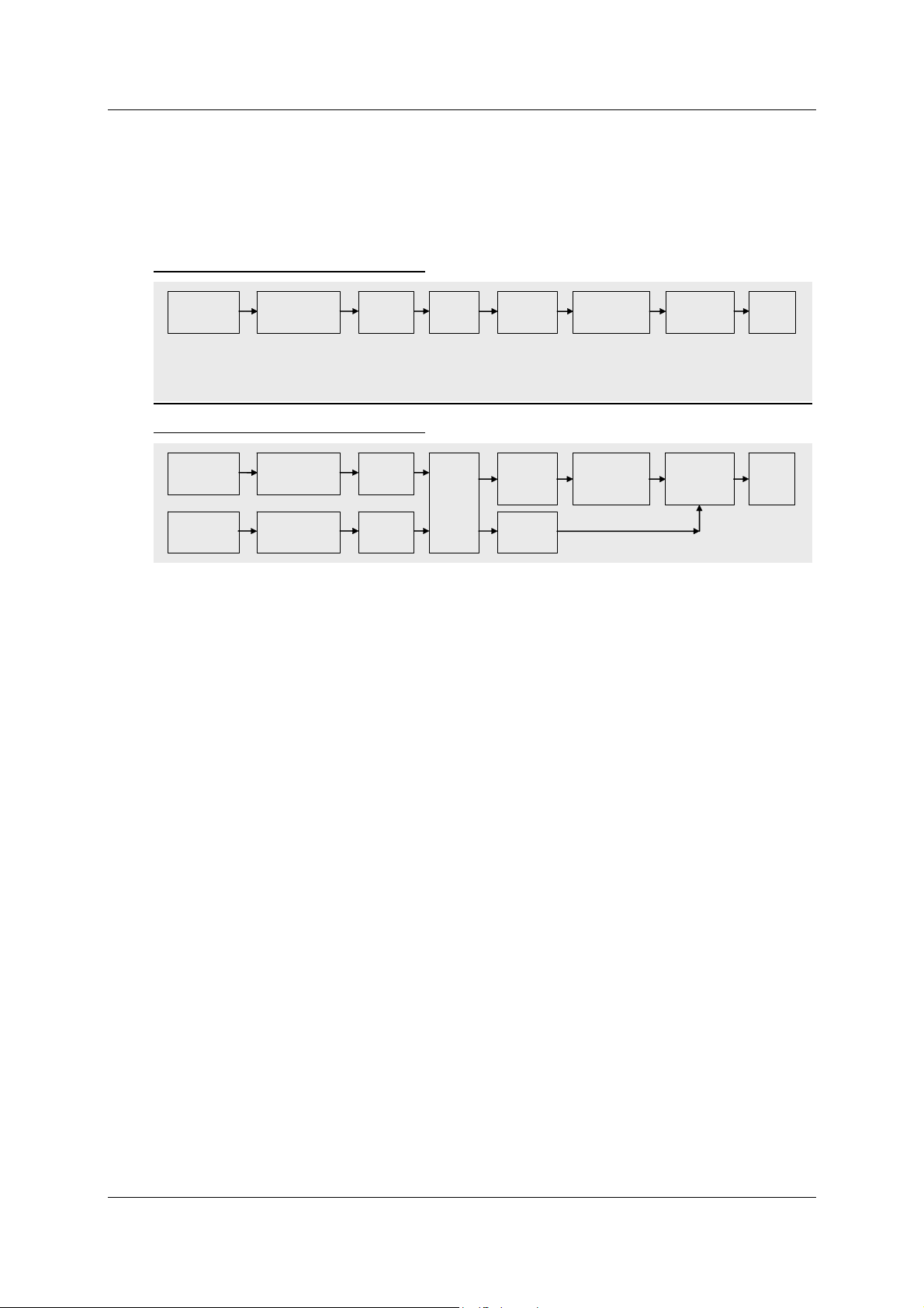
Protocol Description CANopen HIT 1000 / 1500 Page 12
7 Data flow in the HIT 1000/1500 CANopen
The following figures show the flow of data within the HIT 1000 / 1500 CANopen, and
the relevant indices of the Object Dictionary.
Data flow in the HIT 1000 CANopen
Acceleration
Sensor
3D
Calibration
Scaling
T-Compensation
Field Value
5130h
Filter
Operating
Parameters
6011h/6021h
Process Values
6010h
6020h
Transmission
Unit
CAN
Message
Data flow in the HIT 1500 CANopen
Acceleration
Sensor
Turn Rate
Sensor
3D
3D
Calibration
Scaling
T-Compensation
Calibration
Scaling
T-Compensation
Field Value
5130h
Field Value
5131h
Filter
&
Fusion
Operating
Parameters
6011h
6021h
Process
Value
5132h
Process Values
6010h
6020h
Transmission
Unit
CAN
Message
7.1 Sensor Unit
The sensor unit measures the inclination towards the horizontal plane and the turn rate.
The measured values are made digitally available.
The type of the sensor unit (Inclination Transducer) is stored under the Sensor Type.
7.2 Calibration & Scaling
The sensor values are processed in the Calibration & Scaling menu point and made
available as a FieldValue.
7.3 Filter & Fusion
The calibrated sensor values are filtered (HIT 1000 und HIT1500) and merged (only
HIT 1500) in the Filter & Fusion menu point and made available after the operating
parameters unit as a ProcessValue.
7.4 Transmission Unit
If one of the following events occurs, then depending on the preset TransmissionType,
the value of the PDO is sent.
1. The EventTimer has expired (cyclical transmission).
2. One or more Sync objects have been received (synchronous transmission).
Status 2016-11-17 HYDAC ELECTRONIC GMBH Part no.: 669962
Page 49

Protocol Description CANopen HIT 1000 / 1500 Page 13
8 The Object Dictionary
8.1 Set-up of the Object Dictionary
As already mentioned, all the data are stored in the Object Dictionary. The entries
supported by the HIT 1000 / 1500 CANopen are listed in the following chapters. The
index is always shown in hexadecimal notation, according to the specification. For each
entry, the access type must also be specified. CANopen differentiates between the
following Access Types:
Access Types for the Object Dictionary
1. const
Read-only, and always delivers the same value.
2. read only
Read-only, however, the value can be changed during operation.
3. write only
The entry is write-only.
4. read write
The entry can be read and written.
CANopen differentiates between the following areas of the data dictionary:
Areas of the Object Dictionary:
1. Index 0000h .. 1FFF: Communication profile specific entries
Settings which apply to all CANopen devices. These entries are defined in DS301
and DS302.
2. Index 6000h .. 9FFF: Device profile specific entries
Device-specific data which are defined in a Draft Standard. HIT 1000 / 1500 CANFS CANopen has implemented the device profile DS410.
3. Index 2000h .. 5FFF: Manufacturer-specific entries
Manufacturer-specific, additional data which are not defined in any specification.
8.2 Structure of the device-specific part according to DS410
The HIT 1000 / 1500 CANopen implements DS410. This describes the behaviour and
the functionality of inclinometers.
Status 2016-11-17 HYDAC ELECTRONIC GMBH Part no.: 669962
Page 50

Protocol Description CANopen HIT 1000 / 1500 Page 14
9 Entries in the Object Dictionary
Listed below are the functionalities implemented by the HIT 1000 / 1500 CANopen. A
detailed description of the entries can be found in profiles [1] and [5].
9.1 Communication Profile Specific Entries (DS301)
9.1.1 Index 1000h: DeviceType (read only)
Contains the number of the device profile being used, in this case, number 410, as well
as the profile-specific extension, in this case 2, for the support of 2 axes with 16 bit
maximum resolution.
9.1.2 Index 1001h: ErrorRegister (read only)
Contains the actual error condition (see EMCY, and [1]).
9.1.3 Index 1003h: Pre-defined error field (read only)
Errors are made available, which have occurred in the CANopen device and which
were signalised via emergency object (see CiA 301)
9.1.4 Index 1005h: S yncMessageIdentifier (read write)
Use this to adjust the COB ID for the SYNC object.
9.1.5 Index 1008h: ManufacturerDeviceName (const)
Provides the device name as a character string. ("HIT1000").
9.1.6 Index 1009 h: ManufacturerHardwareVersion (const)
Provides the hardware version as a character string (e.g. "01.03").
9.1.7 Index 100Ah: ManufacturerSoftwa reVersion (const)
Provides the software version as a character string (e.g. "03.02"). The first two
characters indicate the version, the last two characters indicate the revision status.
9.1.8 Index 1010h: StoreParameters
By entering the character string "save" (65766173h) the current settings are transferred
to the non-volatile memory.
HIT 1000 / 1500 CANopen does not automatically store the settings if modified,
modifications are stored only when requested.
WARNING: Any changed settings must be saved explicitly using
StoreParameters, otherwise they will be lost when the instrument is switched off
or when the NMT commands Reset Node and Reset Communication are carried
out.
Status 2016-11-17 HYDAC ELECTRONIC GMBH Part no.: 669962
Page 51

Protocol Description CANopen HIT 1000 / 1500 Page 15
CANopen has the option of restoring different parameter areas with the help of various
Sub indeces.
The sub indeces 1, 2, 3 and 4 are supported.
For further information, please see profile [1].
Warning: The Baud rate and NodeID settings remain unchanged with
StoreAllParameters.
Sub indices used:
0: LargestSubindexSupported (read only)
1: StoreAllParameters (read write)
2: StoreCommunicationParameters (read write) (index of 1000h to 1FFFh)
3: StoreApplicationParameters (read write) (index of 6000h to 9FFFh)
4: StoreLssParameters (read write) (index von 2000h to 20FFh)
9.1.9 Index 1011h: RestoreDefaultParame ters
By entering the character string "load" (64616F6Ch) the factory settings are transferred
into the non-volatile memory.
However, the HIT 1000 / 1500 CANopen goes on operating with the actual settings
until switched off or until the commands Reset Node and Reset Communication are
performed.
CANopen has the option of restoring different parameter areas with the help of various
Sub indeces.
The sub indeces 1, 2, 3 and 4 are supported.
For further information, please see profile [1].
Warning: The Baud rate and NodeID settings remain unchanged with
RestoreAllParameters.
Sub indices used:
0: LargestSubindexSupported (read only)
1: RestoreAllParameters (read write)
2: RestoreCommunicationParameters (read write) (index of 1000h to 1FFFh)
3: RestoreApplicationParameters (read write) (index of 6000h to 9FFFh)
4: RestoreLssParameters (read write) (index of 2000h to 20FFh)
9.1.10 Index 1014h: CobIdEmergencyMessage (read write)
Use this to adjust the COB ID for the EMCY object (see EMCY).
9.1.11 Index 1017h: ProducerHeartbeatTime (read write)
Use this to adjust the Heartbeat time to milliseconds. The value 0 indicates that this
function is not active (see Heartbeat).
Status 2016-11-17 HYDAC ELECTRONIC GMBH Part no.: 669962
Page 52

Protocol Description CANopen HIT 1000 / 1500 Page 16
9.1.12 Index 1018h IdentityObject
The Identity Object identifies the HIT 1000 / 1500 CANopen. The identification consists
of four 32bit numbers. The combination of these 4 numbers produces a device ID
which is unique worldwide.
Sub indices used:
0: LargestSubindexSupported (read only)
1: VendorID (read only)
Unique manufacturer code (DAh for HYDAC ELECTRONIC GmbH)
2: ProductCode (read only)
Hydac Electronic product code (z.B: 924854)
3: RevisionNumber (read only)
Revision number of the device
4: SerialNumber (read only)
Serial number of the device
9.1.13 Index 1029h: Error behaviour
Sub indices used:
0: No. of Error Classes (read ony)
1: Communication Error (read write)
0 : Change to NMT state Pre-operational
1 : No change of the NMT state
2 : Change to NMT state Stopped
2: Specific Error Class (read write)
0 : Change to NMT state Pre-operational
1 : No change of the NMT state
2 : Change to NMT state Stopped
9.1.14 Index 1800h / 1801h / 1802h / 1803h: TPDO communication
parameter
These entries determine the PDO transmission. In detail these are:
Parameters for PDO transmission
1. COB ID
Determines the identifier for the PDO. The highest value bit (Bit31) of the entry no
longer belongs to the ID and has the meaning "disable PDO". If this bit is set, then
transmission of the PDO is disabled.
2. Transmission Type
Determines the transmission type.
Values between 0 and 240 mean synchronous transmission. The figure represents
the number of SYNC objects which have to be received before the PDO is sent.
The value 254 indicates a manufacturer-specific transmission and the value 255 a
device-profile-specific transmission. With 254 and 255 the PDO is sent cyclically,
providing a time (Event Time) other than 0 is set.
3. Inhibit Time
defines the minimum interval for the PDO if FEh and FFh were chosen as
transmission type. The value is defined as a multiple of 100µs. The value 0
switches off the inhibit t ime.
4. Reserved – of no significance
Status 2016-11-17 HYDAC ELECTRONIC GMBH Part no.: 669962
Page 53

Protocol Description CANopen HIT 1000 / 1500 Page 17
5. Event Time
Determines the cycle time for asynchronous transmissions for Transmission Types
254 and 255 in milliseconds. The value 0 denotes no time-controlled transmission.
Sub indices used:
0: LargestSubindexSupported (read only)
1: COBIDUsedByPDO (read write)
2: TransmissionType (read write)
3: InhibitTime (read write)
4: Reserved
5: EventTimer(read write)
9.1.15 Index 1A00h / 1A01h / 1A02h / 1A03h: TPDO mapping parameter
Use these entries to determine which data is transferred with the PDO. Sub index 0
indicates the amount of data in the PDO. The index and sub index as well as the
number of bits of the first date are stored in sub index 1, this also applies for the sub
indices 2 to 8.
When supplied, the HIT 1000 / 1500 CANopen has the following entries:
Index 1A00h Strategical Inclination (HIT 1000 und HIT 1500)
sub index Content Meaning
0 3 Three values are transferred in the PDO.
1 60100010h The first value in the PDO is the value of Index 6010h,
sub index 0 with a width of 10h (=16 bits)
2 60200010h The second value in the PDO is the value of Index
6020h, sub index 0 with a width of 10h (=16 bits)
3 50000008h The third value in the PDO is the status of the inclination
measurement
Index 1A01h: Scaled acceleration values (HIT 1000 and HIT1500)
sub index Content Meaning
0 3 Three values are transferred in the PDO.
1 51300110h The first value in the PDO is the value of Index 5130h,
sub index 1 with a width of 10h (=16 bits)
2 51300210h The second value in the PDO is the value of Index
5130h, sub index 2 with a width of 10h (=16 bits)
3 51300310h The third value in the PDO is the value of Index 5130h,
sub index 3 with a width of 10h (=16 bits)
Index 1A02h Scaled rotational values (only HIT 1500)
sub index Content Meaning
0 3 Three values are transferred in the PDO.
1 51310110h The first value in the PDO is the value of Index 5131h,
sub index 1 with a width of 10h (=16 bits)
2 51310210h The second value in the PDO is the value of Index
5131h, sub index 2 with a width of 10h (=16 bits)
3 51310310h The third value in the PDO is the value of Index 5131h,
sub index 3 with a width of 10h (=16 bits)
Status 2016-11-17 HYDAC ELECTRONIC GMBH Part no.: 669962
Page 54

Protocol Description CANopen HIT 1000 / 1500 Page 18
Index 1A03h Inclination motion compensated (only HIT 1500)
sub index Content Meaning
0 2 Two values are transferred in the PDO.
1 51320110h The first value in the PDO is the value of Index 5132h,
sub index 1 with a width of 10h (=16 bits)
2 51320210h The second value in the PDO is the value of Index
5132h, sub index 2 with a width of 10h (=16 bits)
Sub indices used:
0: NumberOfMappedApplicationObjectsInPDO (read write)
Values 0 to 8 are permitted.This means: no PDO is transmitted, or one PDO with
up to 8 values is transmitted.
ObjectToBeMapped (1 to 8) (read write)
In HIT 1000 / 1500 CANopen the following values are permitted among others:
10010008h = Error Register 8bit width
10020020h = Manufacturer Status Register 32bit width
50000008h = Status inclination 8bit width
51300110h = Process value acceleration in direction of the X-axis (see 9.3.3)
51300210h = Process value acceleration in direction of the Y-axis
51300310h = Process value acceleration in direction of the Z-axis
51310110h = Process value turn rate around the X-axis (see 9.3.4)
51310210h = Process value turn rate around the Y-axis
51310310h = Process value turn rate around the Z-axis
51320110h = Process value compensated inclination (same as Slope long16 s.u.)
51320210h = Process value compensated inclination (same as Slope lateral16 s.u.)
60100010h = Process value Slope long16 mit 16bit width (DS410 comp. [5])
60200010h = Process value Slope lateral16 mit 16bit width (DS410 comp. [5])
9.1.16 Index 1F80h: NMT Startup (read / write)
If bit 2 is set, status is changed automatically to "Operational" state immediately after
reaching "Pre-Operational" state (DS302).
Permitted values are: 08h and 0Ch
9.2 Device Profile Specific Entries (DS410)
9.2.1 Index 6000h: Resolution (read only)
This entry contains the resolution of the inclination values in angle degrees.
HIT 1000 / 1500 CANopen returns the value 0Ah.
According to DS 410, this corresponds with a resolution of 0.01° (see [5]).
Status 2016-11-17 HYDAC ELECTRONIC GMBH Part no.: 669962
Page 55

Protocol Description CANopen HIT 1000 / 1500 Page 19
–
9.2.2 Index 6010h: Slope long16 (read only) Statical inclination
This entry contains the inclination in longitudinal direction as a signed 16 bit value (see
[5]).
9.2.3 Index 6011h: Slope long16 operating parameter (read write)
This entry contains the information on the interpretation of the measured value
SlopeLong16.
HIT 1000 / 1500 CANopen by default returns the value 00h (see [5]).
Bit 7
1 Bit 0 Function
0 0
0 1
Inversion off
Inversion on
9.2.4 Index 6020h: Slope lateral16 (read only) Statical inclination
This entry contains the inclination in lateral direction as a signed 16 bit value (see [5] only in devices providing 2 axes).
9.2.5 Index 6021h: Slope lateral16 operating parameter (read write)
This entry contains the information on the interpretation of the measured value
SlopeLateral16 (see 9.2.3).
HIT 1000 / 1500 CANopen by default returns the value 00h (see [5]).
9.3 Manufacturer Specific Entries
9.3.1 Index 2001 h: NodeID
The Node ID is stored in this index.
Sub indices used:
0: NumberOfEntries (read only)
1: CurrentNodeId (read only)
2: DemandedNodeId (read write)
In order for the new Node ID to be effective, the command StoreLssParameters must
first be transmitted and the node must be restarted afterwards.
9.3.2 Index 2002h: Baudrate
The Baud rate is stored in this index.
The allocation of the entry to the Baud rate complies with DS305, Layer Setting
Services and Protocols.
Entry 0 1 2 3 4 5 6 7 8
Baud rate
1000
kbit/s
800
kbit/s
500
kbit/s
250
kbit/s
125
kbit/s
reserved
50
kbit/s
In order for the new Baud rate to be effective, the command StoreLssParameters must
first be transmitted and the node must be restarted afterwards.
20
kbit/s
10
kbit/s
Status 2016-11-17 HYDAC ELECTRONIC GMBH Part no.: 669962
Page 56

Protocol Description CANopen HIT 1000 / 1500 Page 20
Sub indices used:
0: NumberOfEntries (read only)
1: CurrentBaudrate (read only)
2: DemandedBaudrate (read write)
9.3.3 Index 5130h: Scaled acc eleration values
The current process value for the component of the gravitational acceleration in the
direction of the X, Y and Z axis of the inclinometer are deposited in this index.
The values are scaled into 1/100 m/s
The process value 981 corresponds with 9.81 m/s
2
.
2
= 1g.
Sub indices used:
0: NumberOfEnt ries (read only)
1: X component Int16 (read only)
2: Y component Int16 (read only)
3: Z component Int16 (read only)
9.3.4 Index 5131h: Scaled turn rate values
The current process value for the component of the rotational value around the X, Y
and Z-axes of the inclinometer are deposited in this index (measured in radians).
The values are scaled into 0.2 Millirad/s. 2π/s corresponds with one rotation/s.
To say, a process value of 15000 corresponds with a gyro of 3 rad/s.
Sub indices used:
0: NumberOfEnt ries (read only)
1: X component Int16 (read only)
2: Y component Int16 (read only)
3: Z component Int16 (read only)
The following drawing shows the positive turning direction about an imaginary axis.
9.3.5 Index 5132h Inclination in space (motion compensated)
The current process value for the compensated inclination to horizontal in the X, Y and
Z axes are deposited in this index.
The value has a resolution of 0.01° (compare Index 6010h / 6020h)
Sub indices used:
0: NumberOfEnt ries (read only)
1: According to Slope long16 Component Int16 (read only)
2: According to Slope lateral16 Component Int16 (read only)
Status 2016-11-17 HYDAC ELECTRONIC GMBH Part no.: 669962
Page 57

Protocol Description CANopen HIT 1000 / 1500 Page 21
–
9.3.6 Index 5000 h: Status of the inclination measurement
The Status of the inclination measurement is deposited under this index.
Sub indices used:
0: Stat us Uint8 (read only)
The coding carried out is bit by bit as follows:
Bit 7
Reserved
Always 0
3 Bit 2 Bit 1 Bit 0
Serious
error
Device in
motion
Sensor temperature
outside of control range
9.3.7 Further indeces within the range of 2000h to 5FFFh (reserve d)
The indices within this range contain important factory settings which must not be
modified by the customer!
Warning: Each Intervention may lead to malfunction of the inclinometer!
Status 2016-11-17 HYDAC ELECTRONIC GMBH Part no.: 669962
Page 58

Protocol Description CANopen HIT 1000 / 1500 Page 22
10 Layer setting services (LSS) and protocols
The LSS services and protocols, documented in CiA DS305 V2.2 (see [4]), are used for
the inquiry or the modification of certain parameters of the Data Link Layer and the
Application Layer of a LSS slave by a LSS master via the CAN network.
The following parameters are supported:
- Node-ID
- Baud rate
- LSS address, according to identity object 1018h
Access to the LSS slave thereby is made by its LSS address, consisting of:
- Vendor ID
- Product Code
- Revision number
- Serial number
The measuring system supports the following services:
Switch mode services
● Switch mode selective
¾ To address a specific LSS slave
● Switch mode global
¾ To address the total of LSS slaves
Configuration services
● Configure Node ID
¾ Configure Node ID
● Configure bit timing parameters
¾ Configure Baud rate
● Activate bit timing parameters
¾ Activate Baud rate
● Store configured parameters
¾ Store configured parameters
Inquiry services
● Inquire LSS address
¾ Inquire LSS address
● Inquire Node ID
¾ Inquire Node ID
Identification services
● LSS identify remote slave
¾ Identification of LSS slaves within a certain array
● LSS identify slave
¾ Response of all LSS slaves to the previous command
● LSS identify non-configured remote slave
¾ Identification of non-configured LSS slaves, Node ID = FFh
● LSS identify non-configured slave
¾ Response of all LSS slaves to the previous command
Status 2016-11-17 HYDAC ELECTRONIC GMBH Part no.: 669962
Page 59
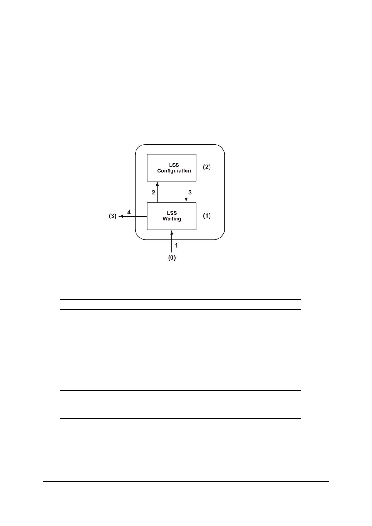
Protocol Description CANopen HIT 1000 / 1500 Page 23
10.1 Finite state automaton, FSA
The FSA is equivalent to a state machine and defines the behaviour of a LSS slave.
This state machine is controlled by LSS COBs produced by the LSS master or NMT
COBs generated by a NMT master or local NMT state transitions.
The LSS Modes support the following states:
(0) Initial: Pseudo-State, shows the activation of the FSAs
(1) LSS waiting: Support for all services as indicated below
(2) LSS configuration: Support for all services as indicated below
(3) Final: Pseudo-State, shows the deactivation of the FSAs
Figure 1: LSS Modes
State behavior of the supported services
Services Waiting Configuration
Switch mode global Yes Yes
Switch mode selective Yes No
Activate bit timing parameters No Yes
Configure bit timing parameters No Yes
Configure Node ID No Yes
Store configuration No Yes
Inquire LSS address No Yes
LSS identify remote slave Yes Yes
LSS identify slave Yes Yes
LSS identify non-configured remote
slave
Yes Yes
LSS identify non-configured slave Yes Yes
LSS FSA state transitions
Status 2016-11-17 HYDAC ELECTRONIC GMBH Part no.: 669962
Page 60

Protocol Description CANopen HIT 1000 / 1500 Page 24
Transition Events Actions
1
Automatic transition after initialisation when
entering either the state NMT PRE
OPERATIONAL state or NMT STOPPED state,
None
or NMT RESET COMMUNICATION state with
Node ID = FFh.
2
LSS 'switch state global' command with
parameters 'configuration_switch' or 'switch state
None
selective' command
3
4
LSS 'switch state global' command with
parameter 'waiting_switch'
Automatic transition when an invalid Node ID has
been changed and the new Node ID could be
successfully stored in non-volatile memory AND
None
None
the state of LSS waiting has been requested.
Once the LSS FSA achieves further state transitions of the NMT FSA on NMT PRE into
OPERATIONAL STOPPED and vice versa, this will not lead to re-entry into the LSS
FSA.
10.2 Transmission of LSS services
By means of LSS services, the LSS master requests the particular services to be
performed by the LSS slave. Communication between LSS master and LSS slave is
performed by means of implemented LSS protocols.
Similar as in the case of SDO transmission, wo COB IDs for sending and receiving are
used in this case as well:
COB ID Meaning
7E4h
7E5h
Table 1: COB IDs for LSS services
LSS-Slave → LSS-Master
LSS-Master → LSS-Slave
10.2.1 LSS message format
The data field of a CAN message being max. 8 bytes long is used by a LSS service as
follows:
CS Data
Byte 0 Byte 1 Byte 2 Byte 3 Byte 4 Byte 5 Byte 6 Byte 7
Table 2: LSS message
Byte 0 contains the Command-Specifier (CS), afterwards 7 bytes of data are
following.
Status 2016-11-17 HYDAC ELECTRONIC GMBH Part no.: 669962
Page 61

Protocol Description CANopen HIT 1000 / 1500 Page 25
10.3 Switch mode protocols
10.3.1 Switch mode global protocol
The given protocol has implemented the Switch mode global service and
controls the state behavior of the LSS slave. By means of the LSS master all LSS slaves
in the network can be switched to Waiting Mode or Configuration Mode.
LSS-Master --> LSS-Slave
COB ID CS Mode
0 1 2 3 4 5 6 7
Reserved by CiA
0 = Waiting Mode
7E5h 04
1 = Configuration
Mode
10.3.2 Switch mode selective protocol
The given protocol has implemented the Switch mode selective service and
controls the state behavior of the LSS slave. By means of the LSS master only this LSS
slave in the network can be switched to Configuration Mode, whose LSS address
attributes correspond with the LSS address.
LSS-Master --> LSS-Slave
COB ID
7E5h
COB ID CS Product-Code
7E5h 65
COB ID CS Revision number
7E5h 66
COB ID CS Serial number
7E5h 67
LSS-Slave --> LSS-Master
0 1 2 3 4 5 6 7
CS
64
LSB MSB
Vendor-Id
Reserved by CiA
0 1 2 3 4 5 6 7
Reserved by CiA
LSB MSB
0 1 2 3 4 5 6 7
Reserved by CiA
LSB MSB
0 1 2 3 4 5 6 7
Reserved by CiA
LSB MSB
Status 2016-11-17 HYDAC ELECTRONIC GMBH Part no.: 669962
Page 62

Protocol Description CANopen HIT 1000 / 1500 Page 26
COB ID CS
7E4h 68
0 1 2 3 4 5 6 7
Reserved by CiA
10.4 Configuration protocols
10.4.1 Configure Node ID protocol
The given protocol has implemented the Configure NMT-address service. By means
of the LSS master the Node ID of a single LSS slave in the network can be configured.
Only one LSS slave may be switched to Configuration Mode for this purpose. For
storage of the new Node ID the Store configuration protocol must be
transmitted to the LSS slave. To activate the new Node ID the NMT service
Communication
LSS-Master --> LSS-Slave
COB ID CS Node ID
7E5h 17 1…127 and 255
LSS-Slave --> LSS-Master
COB ID CS
7E4h 17
Error Code
0: Protocol successfully completed
1…254: Reserved
255: application specific error occurred
Specific Error
if Error Code = 255 --> application specific error occurred,
otherwise reserved by CiA
(82h) must be addressed.
0 1 2 3 4 5 6 7
0 1 2 3 4 5 6 7
Error
Code
Spec.
Error
Reserved by CiA
Reserved by CiA
Reset
10.4.2 Configure bit timing parameters protocol
The given protocol has implemented the Configure bit timing parameters
service. By means of the LSS master the Baud rate of a single LSS slave or of all LSS
slaves in the network can be configured. For the storage of the new Node ID the Store
configuration protocol must be transmitted to the LSS slave.
LSS-Master --> LSS-Slave
COB ID CS
7E5h 19 0 0..8
Status 2016-11-17 HYDAC ELECTRONIC GMBH Part no.: 669962
0 1 2 3 4 5 6 7
Table
Selector
Table
Index
Reserved by CiA
Page 63

Protocol Description CANopen HIT 1000 / 1500 Page 27
LSS-Slave --> LSS-Master
COB ID CS
7E4h 19
Table Selector
0: Standard CiA Baud rate table
Table Index
0: 1 Mbit/s
1: 800 kbit/s
2: 500 kbit/s
3: 250 kbit/s
4: 125 kbit/s
5: reserved!
6: 50 kbit/s
7: 20 kbit/s
8: 10 kbit/s
Error Code
0: Protocol successfully completed
1: selected Baud rate not supported
2…254: Reserved
255: application specific error occurred
Specific Error
if Error Code = 255 --> application specific error occurred,
otherwise reserved by CiA
0 1 2 3 4 5 6 7
Error
Code
Spec.
Error
Reserved by CiA
10.4.3 Activate bit timing parameters protocol
The given protocol has implemented the Activate bit timing par ameters
service and activates the Baud rate defined via Configure bit timing
parameters protocol in all LSS Slaves in the network being in Configuration
Mode.
LSS-Master --> LSS-Slave
COB ID CS Switch Delay [ms]
7E5h 21 LSB MSB
Switch Delay
The parameter Switch Delay defines the length of two delay periods (D1, D2) with
equal length. These are necessary to avoid operating the bus with differing Baud rate
parameters. After the expiration of the time D1 and after an individual processing
duration, the switching is performed internally inside the LSS slave. After the expiration
of the time D2, the LSS slave responds with CAN messages and the newly configured
Baud rate.
Status 2016-11-17 HYDAC ELECTRONIC GMBH Part no.: 669962
0 1 2 3 4 5 6 7
Reserved by CiA
Page 64

Protocol Description CANopen HIT 1000 / 1500 Page 28
The following applies:
Switch Delay > longest occurring processing duration of a LSS slave
10.4.4 Store configuration protocol
The given protocol has implemented the Store configured parameters
service. By means of the LSS master the configured parameters of a single LSS slave
in the network can be stored into the non-volatile memory. Only one LSS slave may be
switched to Configuration Mode for this purpose.
LSS-Master --> LSS-Slave
COB ID CS
7E5h 23
LSS-Slave --> LSS-Master
COB ID CS
7E4h 23
Error Code
0: Protocol successfully completed
1: Store configuration not supported
2…254: Reserved
255: application specific error occurred
Specific Error
if Error Code = 255 --> application specific error occurred,
otherwise reserved by CiA
0 1 2 3 4 5 6 7
Reserved by CiA
0 1 2 3 4 5 6 7
Error
Code
Spec.
Error
Reserved by CiA
10.5 Inquire LSS address protocols
10.5.1 Inquire Identity Vendor ID protocol
The given protocol has implemented the Inquire LSS address service. By means
of the LSS master the Vendor ID of a single LSS slave in the network can be read out.
Only one device can be switched to Configuration Mode.
LSS-Master --> LSS-Slave
COB ID CS
7E5h 90
Status 2016-11-17 HYDAC ELECTRONIC GMBH Part no.: 669962
0 1 2 3 4 5 6 7
Reserved by CiA
Page 65

Protocol Description CANopen HIT 1000 / 1500 Page 29
LSS-Slave --> LSS-Master
COB ID CS
7E4h 90
0 1 2 3 4 5 6 7
Vendor Id (= Index 1018h:01) Reserved by CiA
LSB MSB
10.5.2 Inquire Identity Product Code Protocol
The given protocol has implemented the Inquire LSS address service. By means
of the LSS master the manufacturer's product name of a single LSS slave in the network
can be read out. Only one LSS slave may be switched to Configuration Mode.
LSS-Master --> LSS-Slave
COB ID CS
7E5h 91
LSS-Slave --> LSS-Master
COB ID CS Product Code (= Index 1018h:02)
7E4h 91
0 1 2 3 4 5 6 7
Reserved by CiA
0 1 2 3 4 5 6 7
Reserved by CiA
LSB MSB
10.5.3 Inquire Identity Revision-Number protocol
The given protocol has implemented the Inquire LSS address service. By means
of the LSS master the Identity Revision Number of a single LSS slave in the network can
be read out. Only one LSS slave may be switched to Configuration Mode for this
purpose.
LSS-Master --> LSS-Slave
COB ID CS
7E5h 92
LSS-Slave --> LSS-Master
COB ID CS Revision Number (= Index 1018h:03)
7E4h 92
0 1 2 3 4 5 6 7
Reserved by CiA
0 1 2 3 4 5 6 7
Reserved by CiA
LSB MSB
Status 2016-11-17 HYDAC ELECTRONIC GMBH Part no.: 669962
Page 66

Protocol Description CANopen HIT 1000 / 1500 Page 30
10.5.4 Inquire Identity Serial Number protocol
The given protocol has implemented the Inquire LSS address service. Via the
LSS master the Serial Number of a single LSS slave in the network can be read out.
Only one LSS slave may be switched to Configuration Mode for this purpose.
LSS-Master --> LSS-Slave
COB ID CS
7E5h 93
LSS-Slave --> LSS-Master
COB ID CS
7E5h 93
0 1 2 3 4 5 6 7
Reserved by CiA
0 1 2 3 4 5 6 7
Serial Number (= Index 1018h:04) Reserved by CiA
LSB MSB
10.5.5 Inquire Node ID protocol
The given protocol has implemented the Inquire Node ID service.
Via the LSS master the Serial Number of a single LSS slave in the network can be read
out. Only one LSS slave can be switched to Configuration Mode.
LSS-Master --> LSS-Slave
COB ID CS
7E5h 94
LSS-Slave --> LSS-Master
COB ID CS Node ID
7E4h 94 1…127 and 255
Node-ID
Corresponds to the Node ID of the selected device. If the Node ID has been recently
changed by the Configure Node ID service, the original Node ID is returned.
Only after implementation of the NMT Service Reset Communication (82h), the
current Node ID is returned.
0 1 2 3 4 5 6 7
Reserved by CiA
0 1 2 3 4 5 6 7
Reserved by CiA
Status 2016-11-17 HYDAC ELECTRONIC GMBH Part no.: 669962
Page 67

Protocol Description CANopen HIT 1000 / 1500 Page 31
10.6 Identification Protocols
10.6.1 LSS identify remote slave protocol
The given protocol has implemented the LSS identify remote slaves service.
By means of the LSS master LSS slaves in the network can be identified within a certain
range. All LSS slaves with matching Vendor ID, Product Code, Revision No. - area and
Serial No. - area, respond by the LSS identify slave protocol.
LSS-Master --> LSS-Slave
COB ID CS Vendor-Id
7E5h 70
COB ID CS Product-Code
7E5h 71
COB ID CS Revisi on- Number-Low
7E5h 72
COB ID CS Revision-Number-High
7E5h 73
COB ID CS Serial-Number-Low
7E5h 74
COB ID CS Serial Number High
7E5h 75
0 1 2 3 4 5 6 7
Reserved by CiA
LSB MSB
0 1 2 3 4 5 6 7
LSB MSB
0 1 2 3 4 5 6 7
LSB MSB
0 1 2 3 4 5 6 7
LSB MSB
0 1 2 3 4 5 6 7
LSB MSB
0 1 2 3 4 5 6 7
LSB MSB
Reserved by CiA
Reserved by CiA
Reserved by CiA
Reserved by CiA
Reserved by CiA
Status 2016-11-17 HYDAC ELECTRONIC GMBH Part no.: 669962
Page 68

Protocol Description CANopen HIT 1000 / 1500 Page 32
10.6.2 LSS identify slave protocol
The given protocol has implemented the LSS identify slave service. All LSS
slaves with matching LSS address attributes given in the LSS identify remote
slaves protocol, respond by this protocol.
LSS-Slave --> LSS-Master
COB ID CS
7E4h 79
0 1 2 3 4 5 6 7
Reserved by CiA
10.6.3 LSS identify non-configured remote slave protocol
The specified protocol has implemented the LSS identify non-configured
remote slave service. By means of the LSS-Master all non-configured LSS
Slaves (Node ID = FFh) in the network are identified.
the
LSS identify non-configured remote slave protocol.
LSS-Slave --> LSS-Master
COB ID CS
7E4h 76
0 1 2 3 4 5 6 7
The related LSS Slaves respond by
Reserved by CiA
10.6.4 LSS identify non-configured slave Protocol
The specified protocol has implemented the LSS identify non-configured
slave service . All LSS slaves having an invalid Node ID (FFh) respond by this
protocol after having completed the LSS identify non-configured slave
protocol.
LSS-Slave --> LSS-Master
COB ID CS
7E4h 80
0 1 2 3 4 5 6 7
Reserved by CiA
Status 2016-11-17 HYDAC ELECTRONIC GMBH Part no.: 669962
Page 69

Protocol Description CANopen HIT 1000 / 1500 Page 33
11 Connection
The connection can be carried out by means of the enclosed device specific pin assignment,
see user manual HIT 1000 / 1500 CANopen (part no.: 669963, the manual is supplied with the
HIT 1000 / 1500 CANopen).
11.1 Switching on the supply voltage
After connection and all settings have been carried out, the supply voltage can be
switched on.
After POWER ON and finishing the initialisation, the measuring system enters the
PRE-OPERATIONAL state. This status is acknowledged by the Boot-Up message
COB ID 700h+Node ID”. If the measuring system detects an internal error, an emergency
“
message containing the error code is transmitted (see
In PRE-OPERATIONAL state, at first, only a parameter setting via Service Data
Objects is possible. But it is possible to configure PDOs with the help of SDOs. If the
measuring system has entered the OPERATIONAL state, a transmission of PDOs is
possible as well (see 6.6).
6.4).
11.2 Setting the Node ID and Baud rate by means of LSS services
11.2.1 Configuration of the Node ID, sequence
Assumption:
• LSS address unknown
• only one LSS slave should be in the network
• the Node ID 12 dec. shall be set
Procedure:
¾ Switch LSS-Slave to Configuration Mode using command
Specifier 04 Switch mode global protocol, Mode = 1.
(see 10.3)
¾ Perform command Specifier 17 Configure NMT-Address
protocol, Node-ID = 12. (see 10.4.1)
--> Wait for feedback and check successful execution,
--> Error Code = 0.
Status 2016-11-17 HYDAC ELECTRONIC GMBH Part no.: 669962
Page 70

Protocol Description CANopen HIT 1000 / 1500 Page 34
¾ Carry out command Specifier 23 Store configuration protocol
--> Wait for feedback and check successful execution,
--> Error Code = 0 (see10.4.4).
¾ Switch off the supply voltage of the LSS slave, then switch on again.
Now the new configuration is activated.
11.2.2 Configuration of the Baud rate, sequence
Assumption:
• LSS address unknown
• only one LSS slave should be in the network
• the Baud rate 125 kbit/s shall be set
Procedure:
¾ Perform NMT command Specifier Stop Remote Node (02h) in order
to switch LSS-Slave into Stopped state . The LSS slave shouldn’t
send any more CAN-messages
--> Heartbeat switched off (see 6.6).
¾ Switch LSS-Slave to Configuration Mode using command
Specifier Switch mode global protocol, Mode = 1.
(see 10.3.1).
¾ Perform command Specifier 19 Configure bit timing
parameters protocol , Table Selector = 0, Table Index = 4
--> wait for feedback and check successful execution,
--> Error Code = 0
(see 10.4.2).
¾ Carry out command Specifier 21 Activate bit timing
parameters protocol in order to activate the new Baud rate.
(see 10.4.3).
¾ Carry out Command Specifier 23 Store configuration
protocol .
--> Wait for feedback and check successful execution,
--> Error Code = 0 (see10.4.4).
¾ Switch off the supply voltage of the LSS slave, then switch on again.
Now the new configuration is activated.
Status 2016-11-17 HYDAC ELECTRONIC GMBH Part no.: 669962
Page 71

Protocol Description CANopen HIT 1000 / 1500 Page 35
12 Commissioning
12.1 CAN interface
The CAN bus interface is defined by the international standard ISO/DIS 11898 and
specifies the two lowest layers of the ISO/DIS CAN Reference Model.
The conversion of the measuring system information to the CAN message format (CAN
2.0A) is done by a CAN-controller. The function of the CAN-controller is controlled by a
watchdog.
The CANopen Communication Profile (CiA standard DS 301, see [1]) is a subset of
CAN Application Layer (CAL) and describes how the services are used by the devices.
The CANopen Profile allows the definition of device profiles for decentralized I/O.
The measuring system with CANopen protocol supports the Device Profile for
inclinometers (CiA Draft Standard 410, Version 1.3.0, see [5]).
The communication functionality and objects, used in the measuring device profile, are
described in an EDS-File (Electronic Data Sheet). When using a CANopen
Configuration Tool (e.g.: CANSETTER), the user can read out the objects of the
measuring system (SDOs) and program the functionality.
12.2 EDS file
The EDS (electronic datasheet) contains all information on the measuring systemspecific parameters and the measuring system’s operating modes. The EDS file is
integrated using the CANopen network configuration tool to correctly configure or
operate the measuring system.
The EDS file matching the device can be identified by the device name and by the
device related major revision number in its file name.
The file including the its CANopen interface description can be found and downloaded
from our homepage. Address: http://www.hydac.de/de-en/service/download-softwareauf-anfrage/software/software-download/electronic.html.
Status 2016-11-17 HYDAC ELECTRONIC GMBH Part no.: 669962
Page 72

Protocol Description CANopen HIT 1000 / 1500 Page 36
HYDAC ELECTRONIC GMBH
Hauptstr. 27
D-66128 Saarbruecken
Germany
Web: www.hydac.com
E-Mail: [email protected]
Tel.: +49 (0)6897 509-01
Fax.: +49 (0)6897 509-1726
HYDAC Service
For enquiries regarding repairs, please contact HYDAC Service.
HYDAC SERVICE GMBH
Hauptstr. 27
D-66128 Saarbruecken
Germany
Tel.: +49 (0)6897 509-1936
Fax: +49 (0)6897 509-1933
Note
The information in this manual relates to the operating conditions and applications described.
For applications and operating conditions not described, please contact the relevant
technical department.
If you have any questions, suggestions, or encounter any problems of a technical nature,
please contact your Hydac representative.
Status 2016-11-17 HYDAC ELECTRONIC GMBH Part no.: 669962
 Loading...