

Page 1
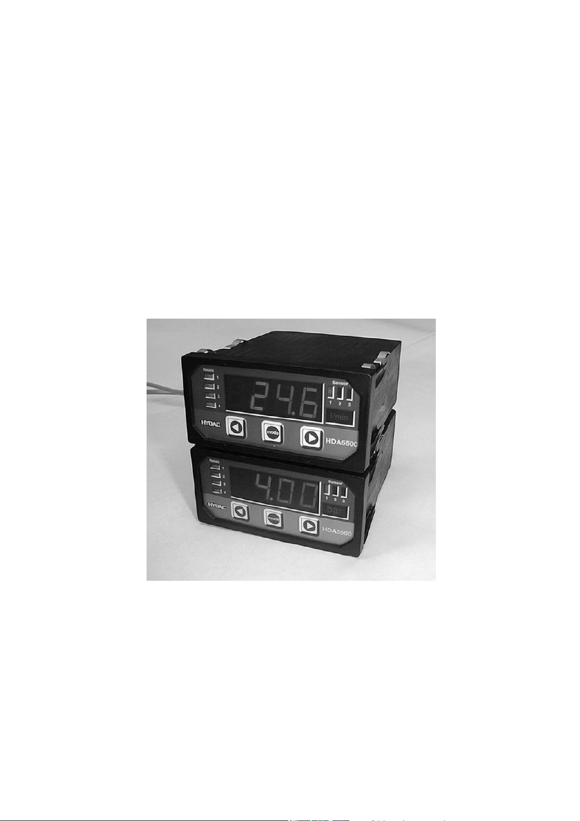
Digital Display Unit
HDA 5500
for Oil Condition Sensor HLB 1000 and
Contamination Sensor CS 1000
User Manual
HDA 5500-0-2-AC-006 (CM1k)
HDA 5500-0-2-DC-006 (CM1k)
Status: 25.06.2008
Part No. 669731
Page 2

HDA 5500 for HLB 1000 and CS 1000
CONTENTS
1 Introduction 3
1.1 European standards compatibility 3
2 Safety instructions 3
3 Functions 3
4 Operating keys 4
5 Selecting and displaying the unit of measurement 4
6 Installation and commissioning 5
6.1 Mechanical installation 5
6.2 Electrical connection 5
6.3 Supply voltage 6
7 Programming 7
7.1 Adjusting the basic settings 7
7.2 Overview of basic settings menu 8
8 Connecting the Oil Condition Sensor HLB 1000 / Contamination Sensor
CS 1000
8.1 HDA 5500 and Oil Condition Sensor HLB 1000 17
8.2 HDA 5500 and Contamination Sensor CS 1000 17
9 Digital display 18
9.1 Standard display 18
9.2 Special display 18
9.3 Sequential analogue output of the HLB 1000 19
9.4 Sequential analogue output of the CS 1000 20
10 Output response 21
10.1 Analogue output 21
10.1.1 Analogue output set to 4 .. 20 mA 21
10.1.2 Analogue output set to 0 .. 10 V 21
10.2 Switching outputs 22
10.2.1 Switching mode 22
10.2.1a) Switch point and hysteresis (SP) 22
10.2.1b) Switching window (Win) 22
10.3 Connection of up to four switching outputs 23
11 Adjusting switch points and hystereses 24
11.1 Switching outputs 24
11.2 Switching window 24
17
12 Programming enable 25
12.1 Altering the operating programming enable 25
12.2 Altering the main programming enable 26
13 Technical specifications 27
14 Model code HDA 5500 28
15 Unit dimensions 29
16 Electrical connections 30
17 Error messages 31
18 HYDAC Service 31
- 2 -
Page 3

HDA 5500 for HLB 1000 and CS 1000
1 Introduction
The individual components and the final assembly of the Digital Display Unit HDA 5500 are
subject to strict quality controls. Each HDA 5500 is individually calibrated and subjected to a
final test. In this way we can guarantee that the unit is fault-free on despatch and conforms to
the given specifications. However, if there is a cause for complaint, please return the unit to
us outlining the fault.
The HDA 5500 digital display unit is maintenance-free and operates perfectly when used
according to the specifications. If faults do nonetheless arise, please contact HYDAC
Service. Incorrect installation or interference by anybody other than HYDAC personnel will
invalidate all warranty claims.
1.1 European standards compatibility
The HDA 5500 digital display unit carries the
approval requirements currently applicable in Germany and to the European standards for
operating these units. The applicable directives on electromagnetic compatibility and the
safety regulations according to the low voltage directive are therefore guaranteed.
This product complies with the regulations of the following European Directive:
EN 61000–6–1 / 2 / 3 / 4
We reserve the right to make technical modifications.
- mark and therefore corresponds to the
2 Safety instructions
The HDA 5500 digital display unit can be operated safely provided it is used in accordance
with its proper, designated use. However, in order to avoid any risk to the operator or any
damage due to incorrect handling of the unit, please adhere strictly to the following safety
instructions:
• The HDA 5500 must not be put into service if any known defects, either electrical or
mechanical, are apparent.
• The unit must be installed exactly according to the instructions.
• Read the information on the type code label.
• Fault investigation and repairs must only be carried out by HYDAC Service.
• All relevant and generally recognised safety requirements must be adhered to.
3 Functions
The HDA 5500 for Condition Monitoring sensors is specifically designed for use with the Oil
Condition Sensor HLB 1000 or the Contamination Sensor CS 1000; it has the following
functions:
• Display of the lowest or peak value (slave pointer function)
• Display of the pre-set switch point
• Switching outputs via relay switching contacts
• Analogue output 4..20 mA or 0..10 V can be selected
• Programming functions can be disabled to prevent subsequent unauthorised adjustment
of the settings
• RS 232 serial interface
Specifically for HLB 1000
• Display of the temperature and the relative humidity as absolute values
• Display of the relative change in viscosity and dielectric constant in %
• Display of the status signal of the HYDACLab ® (See Point 9.3)
Specifically for CS 1000
• Display of the particle contamination in ISO, SAE or NAS cleanliness codes
- 3 -
Page 4
HDA 5500 for HLB 1000 and CS 1000
MODE
MODE
%
%
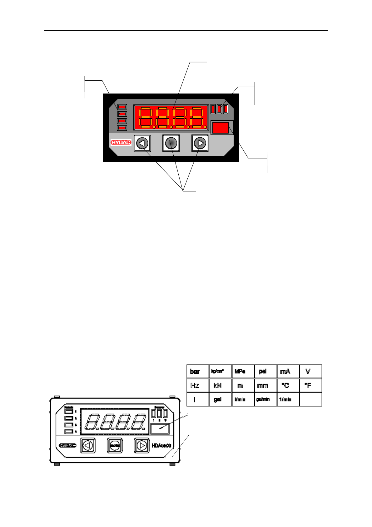
4 Operating keys
LED display
f active
o
switc hing points
Relais
1
2
3
4
4-digit
igital display
d
Sensor
1 2 3
HDA5500
Keys for adjusting the
switching points,
switch-back points and
the menu functions
LED display
of active
sensor
isplay of
D
unit of measurement
sensor 1, 2, 3 or 4
5 Selection and display of the unit of measurement
The operator can select the appropriate unit label from a printed sheet and this is then
displayed with background lighting. The label can be changed at any time.
Procedure:
• Disconnect the unit from supply voltage.
• Remove the front frame of the unit by hand.
• Loosen the 4 front plate screws.
• Press lightly on the back panel of the unit to push out the front side (display section) by a
few millimetres.
• Cut the label with the required unit from the sheet supplied.
• Insert the label into the slot on the side.
• Press lightly on the front panel to push it back on.
• Screw the front plate back in place.
• Put the front frame back on.
Indication of unit (of measurement) using label from sheet
Front frame
- 4 -
Page 5
HDA 5500 for HLB 1000 and CS 1000
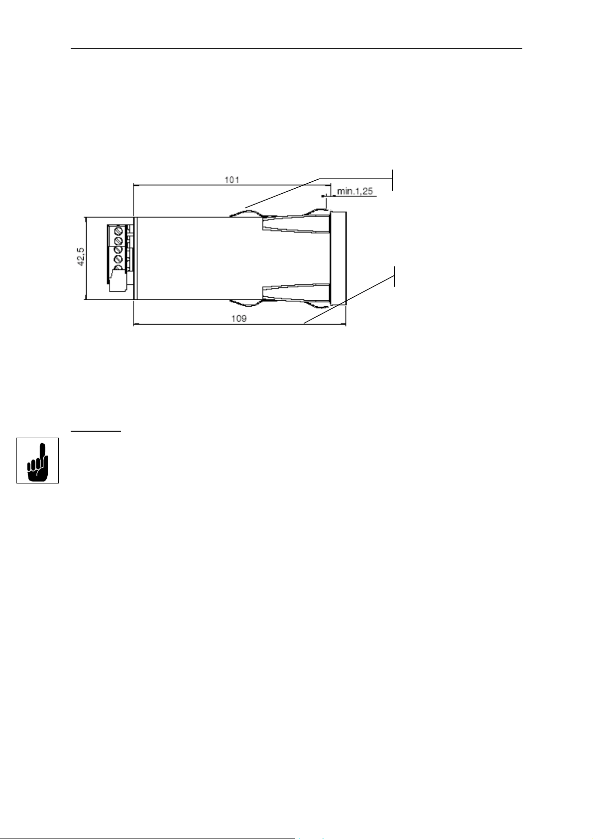
6 Installation and commissioning
6.1 Mechanical installation
The HDA 5500 is a control panel unit with a standard mounting housing 96 x 48 mm and
requires a control panel cut-out: 92 x 45 mm
• Control panel thickness: at least 1.25 mm
• Mounting depth: at least 150 mm
Panel clips
Panel thickness
Clamping guides
6.2 Electrical connection
The electrical connection must be carried out by a qualified electrician in accordance with
relevant regulations in the country concerned (in Germany: VDE 0100).
Important
In order to fulfil the relevant EMC standards, subject to the ambient conditions, the screening
effect of the control box must comply with the EMC standard.
Additional installation notes which, from experience, reduce the effect of electromagnetic
interference:
• Make line connections as short as possible.
• Use screened lines (e.g. LIYCY 4 x 0.5 mm²).
• The cable screening must be fitted by qualified personnel subject to the ambient
conditions and with the aim of suppressing interference.
• Direct proximity to interference must be avoided as far as possible.
If inductive loads are to be switched using the relays, varistors or regenerative diodes must
be used on the load to prevent high switch-off surges.
:
- 5 -
Page 6
HDA 5500 for HLB 1000 and CS 1000
12..32 VDC
85..265 VAC 50 / 60 Hz
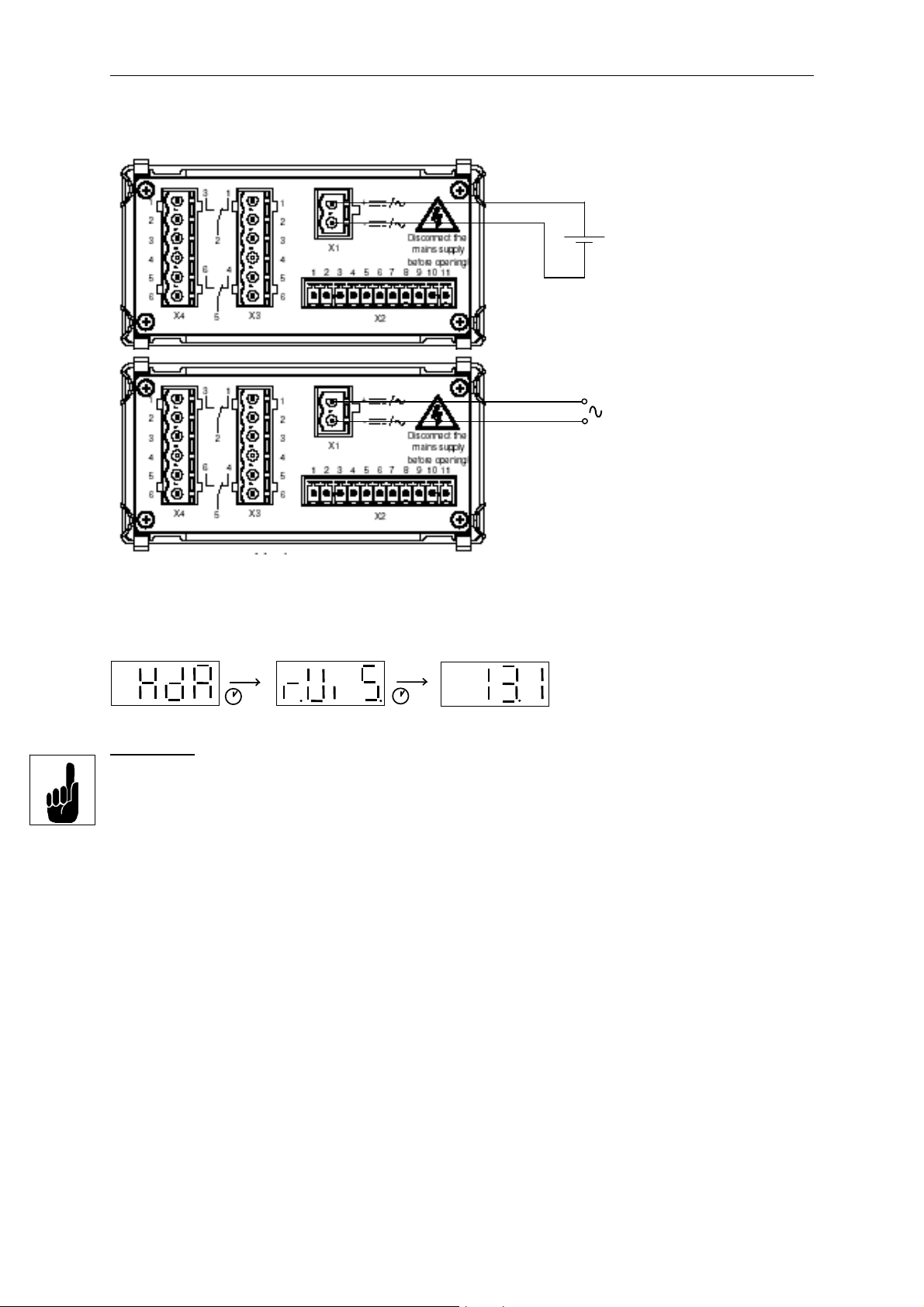
6.3 Supply voltage
The supply voltage is connected to terminal X1.
HDA 5500–0–2–DC–XXX
(see type code label)
HDA 5500–0–2–AC–XXX
(see type code label)
After switching on the supply voltage, the unit displays HdA for approximately 2 s. Then the
number of the sensor set as the primary display is shown. After a further 2 s (approx.) the
actual value is displayed.
2 s
2 s
Important:
Before sensors are connected, the HDA 5500 must be set appropriately.
If there is no input signal, or during the reference phase (up to 2 minutes), then, depending
on the type of signal, the following will be displayed:
• Starting value of the measuring range - flashing
- 6 -
Page 7
HDA 5500 for HLB 1000 and CS 1000
7 Programming
In order to adapt the unit to a particular application, the HDA 5500 is programmed by varying
the basic settings. The basic settings are combined in a menu.
Important:
When the menu is activated, no switching functions are carried out.
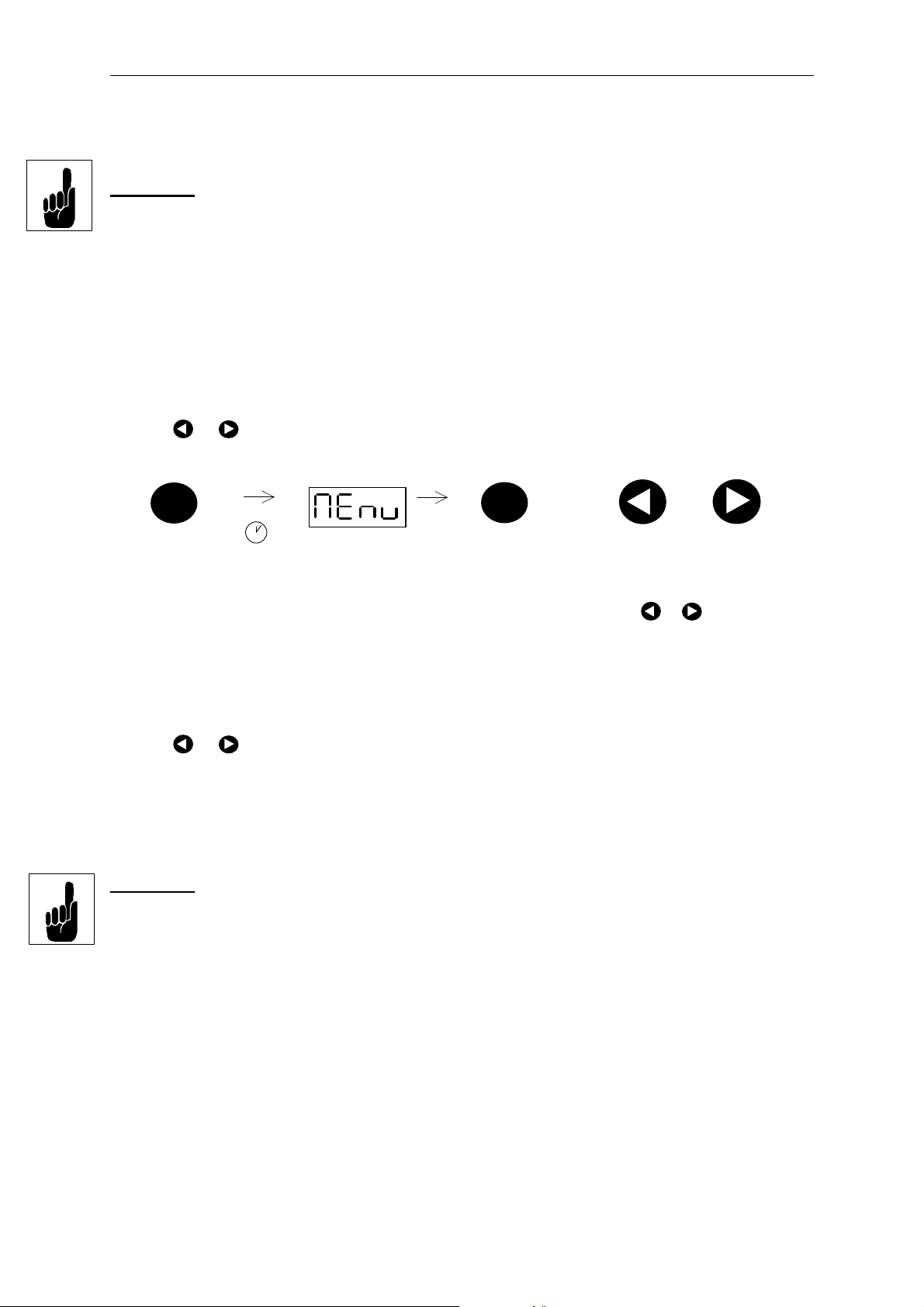
7.1 Adjusting the basic settings
To change the basic settings, the menu must be activated.
Procedure for activating the menu:
• During normal operation, press the MODE key and hold down for at least 5 s.
• MEnu (Menu) is displayed.
• After approximately 2 s the display changes and the first menu point is displayed.
• Press MODE again until the required menu point appears in the display.
• After approximately 2 s the display changes and the actual setting is displayed.
• Use or
• Press MODE again until the next required menu point appears in the display.
to change the setting.
mode
5s
Press Mode key and hold
down until Menu appears
Procedure for accepting and storing changes and to close the menu:
• Press MODE until the menu point End is displayed.
• After approximately 2 s the display changes and No is displayed.
• Use
• Confirm with MODE.
If the basic settings have been changed and the menu has been closed with Yes, then for
approximately 2 s ProG (Programming) is displayed when leaving the menu. The changed
settings are then saved in the HDA 5500. Afterwards the display returns to normal operation.
Important:
If no key is pressed for approximately 25 s, then the menu automatically closes down. Any
changes which may have been made will not be accepted or saved.
or
Menu is displayed
Release mode key
to change the setting to Yes.
mode
Press mode key until
the required menu
point is displayed
Use
the setting, then select the
next menu point
or
to change
- 7 -
Page 8
HDA 5500 for HLB 1000 and CS 1000
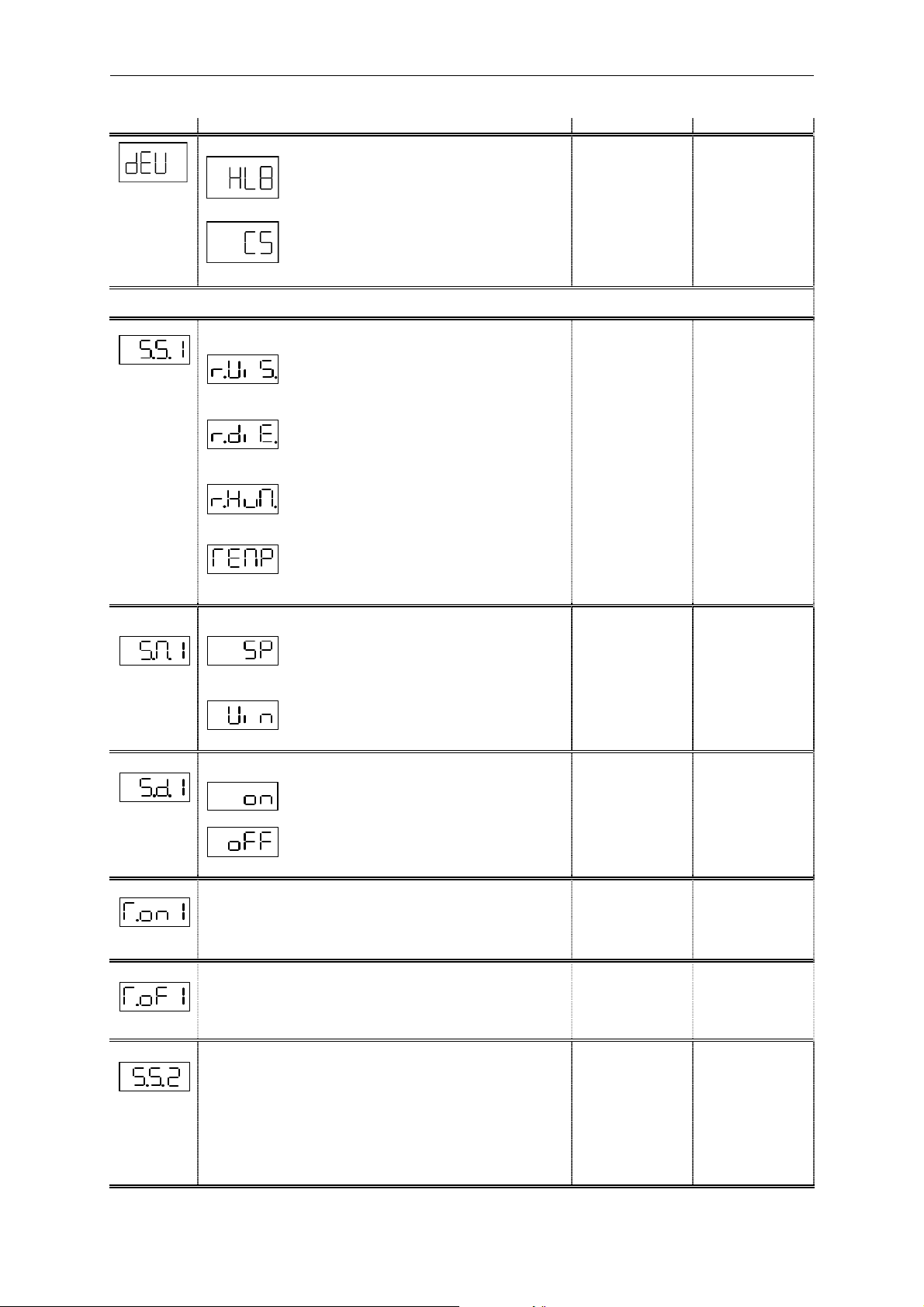
7.2 Overview of basic settings menu
Menu point Setting Setting range Default setting
Device:
Device selected to display the values measured
by the HLB 1000 connected
Device selected to display the values measured
by the CS 1000 connected
When HLB 1000 is selected
HLB,
CS
HLB
Allocation switching output 1 (S.S.1)
Switching output 1 allocated to the signal
of rel. change in viscosity
Switching output 1 allocated to the signal
of rel. change in dielectric constant
Switching output 1 allocated to the signal
of rel. humidity
Switching output 1 allocated to the signal
of temperature
Switching function switching output 1 (S.M.1)
Switching output 1 set to switch point and
hysteresis mode
Switching output 1 set to switching window mode
Switching direction switching output 1 (S.d.1)
Relay activated
r.ViS.
r.diE.
r.HuM.
TEMP.
SP
Win
on
oFF
r.ViS.
SP
on
Relay deactivated
Switch on delay switching output 1 (T.on1)
Time, in seconds, which must elapse once the particular switch
point has been reached or exceeded in order for a switching
function to occur.
Switch-off delay switching output 1 (T.oF1)
Time, in seconds, which must elapse once the value has fallen
below the particular switch-back point in order for a switching
function to occur.
Switching function switching output 2 (S.S.2)
Similar to switching output 1 (see above), and likewise for:
• Switching mode (S.M.2)
• Switching direction (S.d.2)
• Switch-on delay (T.on.2)
• Switch-off delay (T.oF.2)
0..99.99 s
0..99.99 s
r.ViS.
r.diE.
r.HuM.
TEMP.
SP
Win
on
oFF
0..99.99 s
0..99.99 s
0
0
r.ViS.
SP
on
0
0
- 8 -
Page 9
HDA 5500 for HLB 1000 and CS 1000
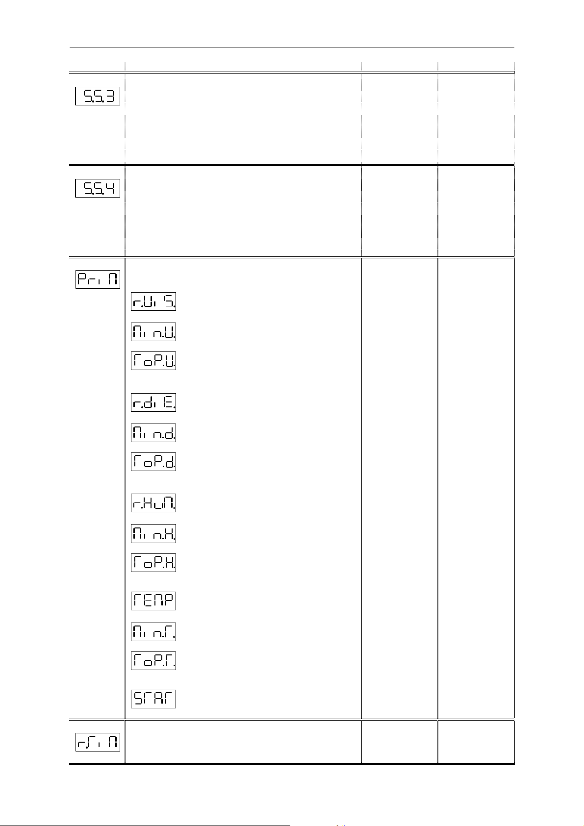
Menu point Setting Setting range Default setting
Switching function switching output 3 (S.S.3)
Similar to switching output 1 (see above), and likewise for:
• Switching mode (S.M.3)
• Switching direction (S.d.3)
• Switch-on delay (T.on.3)
• Switch-off delay (T.oF.3)
Switching function switching output 4 (S.S.4)
Similar to switching output 1 (see above), and likewise for:
• Switching mode (S.M.4)
• Switching direction (S.d.4)
• Switch-on delay (T.on.4)
• Switch-off delay (T.oF.4)
Primary display (PriM)
Value which is displayed permanently:
Measured value of rel. change in viscosity
Lowest value of rel. change in viscosity
r.ViS.
r.diE.
r.HuM.
TEMP.
SP
Win
on
oFF
0..99.99 s
0..99.99 s
r.ViS.
r.diE.
r.HuM.
TEMP.
SP
Win
on
oFF
0..99.99 s
0..99.99 s
r.ViS.
Min.V.
ToP.V.
r.ViS.
SP
on
0
0
r.ViS.
SP
on
0
0
r.ViS.
Peak value of rel. change in viscosity
Meas. value of rel. change in dielectric constant
Lowest value of rel. change in dielectric constant
Peak value of rel. change in dielectric constant
Measured value of rel. humidity
Lowest value of rel. humidity
Peak value of rel. humidity
Measured value of temperature
Lowest value of temperature
r.diE.
Min.d.
ToP.d.
r.HuM.
Min.H.
ToP.H.
TEMP.
Min.T.
ToP.T.
Peak value of temperature
Status of the HYDACLab (see Point 9.3)
Reset time (r.TiM)
Indicates how long in seconds the last peak / lowest value is
displayed for
STAT.
0 .. 3.600 s
0
- 9 -
Page 10
HDA 5500 for HLB 1000 and CS 1000
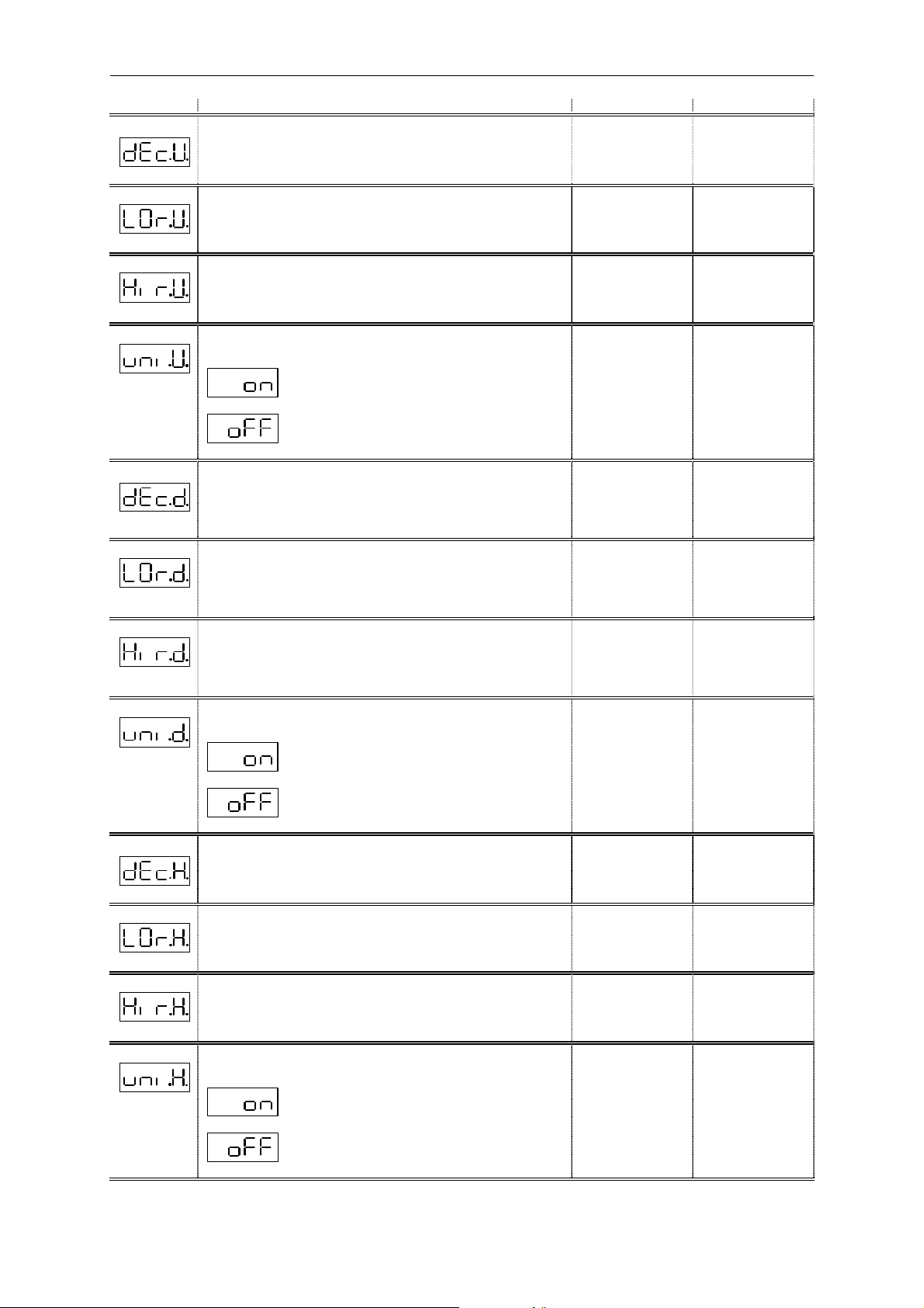
Menu point Setting Setting range Default setting
Decimal place for display of rel. change in viscosity (dEc.V.)
Decimal place(s) when displaying measured values of
rel. change in viscosity
0 .. 0.000
0.0
Lower display range of rel. change in viscosity (LOr.V.)
Lower limit of the display range of rel. change in viscosity
Upper display range of rel. change in viscosity (Hir.V.)
Upper limit of the display range of rel. change in viscosity
Background lighting for the unit label for rel. change in
viscosity (uni.V.)
Lighting behind unit label is switched on
Lighting behind unit label is switched on
Decimal place for display of rel. change in dielectric
constant (dEc.d.)
Decimal place(s) when displaying measured values of
rel. change in dielectric constant
Lower display range of rel. change in dielectric constant
(LOr.d.)
Lower limit of the display range of rel. change in
dielectric constant
Upper display range of rel. change in dielectric constant
(Hir.d.)
Upper limit of the display range of rel. change in dielectric
constant
-999..9899
-899..9999
on
oFF
0 .. 0.000
-999..9899
-899..9999
-30.0
30.0
on
0.0
-30.0
30.0
Background lighting for the unit label for rel. change in
dielectric constant (uni.d.)
Lighting behind unit label is switched on
Lighting behind unit label is switched on
Decimal place for display of rel. humidity (dEc.H.)
Decimal place(s) when displaying measured values of the
rel. humidity
Lower display range of rel. humidity (LOr.H.)
Lower limit of the display range of rel.
humidity
Upper display range of rel. humidity (Hir.H.)
Upper limit of the display range of rel. humidity
Background lighting for the unit label for rel. humidity
(uni.H.)
Lighting behind unit label is switched on
on
oFF
0 .. 0.000
-999..9899
-899..9999
on
oFF
on
0.0
0.0
100.0
on
Lighting behind unit label is switched on
- 10 -
Page 11

HDA 5500 for HLB 1000 and CS 1000
Menu point Setting Setting range Default setting
Decimal place for display of temperature (dEc.T.)
Decimal place(s) when displaying measured values of
temperature
0 .. 0.000
0.0
Lower display range of temperature (LOr.T.)
Lower limit of the display range
of temperature
Upper display range of temperature (Hir.T.)
Upper limit of the display range of
the temperature
Background lighting for the unit label for temperature
(uni.T.)
Lighting behind unit label is switched on
Lighting behind unit label is switched on
Allocation of the analogue output to signal (ouT.S)
the analogue output displays rel. change in
viscosity
the analogue output displays rel. change in
dielectric constant
-999..9899
-899..9999
on
oFF
r.ViS.
r.diE.
r.HuM.
TEMP.
-25.0
100.0
oFF
r.ViS.
the analogue output displays rel. humidity
the analogue output displays temperature
Output signal (ouT.M)
4..20 mA output signal
0..10 V output signal
Software version (VErS)
Displays the software version (for reference only)
To close basic settings (End)
Basic settings menu closes. Changed settings are
saved.
Basic settings can still be altered
MA
VoLT
YES
no
VoLT
no
- 11 -
Page 12

HDA 5500 for HLB 1000 and CS 1000
Menu point Setting Setting range Default setting
When CS 1000 is selected
Important:
The default settings of the upper and lower limits of channels 1 to 4 (LO.1 to LO.4 and Hi.1
to HI.4) correspond to the values for operating the HLB 1000 on the HDA 5500.
When operating the CS1000 on the HDA5500 please note that: The default setting ranges
pre-set in the CS 1000 for the analogue signal output forms HDA.ISO, HDA.SAE or
HDA.NAS must be changed as follows.
HDA.ISO signal:
LO.1 to LO.4 = 0.0
Hi.1 to HI.4 = 24.4
HDA.SAE or HDA.NAS signal:
LO.1 to LO.4 = 0.0
Hi.1 to HI.4 = 14.0
Allocation of switching output 1 (S.S.1)
Switching output 1 allocated to the signal
From channel 1
Channel 1
Channel 2
Channel 3
Channel 4
Channel 1
From channel 2
Switching output 1 allocated to the signal
Switching output 1 allocated to the signal
From channel 3
Switching output 1 allocated to the signal
From channel 4
Switching mode switching output 1 (S.M.1)
Switching output 1 set to switch point and
hysteresis mode
Switching output 1set to switching window mode
Switching direction switching output 1 (S.d.1)
Relay activated
Relay deactivated
Switch on delay switching output 1 (T.on1)
Time, in seconds, which must elapse once the particular switch
point has been reached or exceeded in order for a switching
function to occur.
SP
Win
on
oFF
0..99.99 s
SP
on
0
Switch off delay switching output 1 (T.oF1)
Time, in seconds, which must elapse once the value has fallen
below the particular switch-back point in order for a switching
function to occur.
0..99.99 s
0
- 12 -
Page 13

HDA 5500 for HLB 1000 and CS 1000
Menu point Setting Setting range Default setting
Allocation of switching output 2 (S.S.2)
Similar to switching output 1 (see above), and likewise for:
• Switching mode (S.M.2)
• Switching direction (S.d.2)
• Switch-on delay (T.on.2)
• Switch-off delay (T.oF.2)
Allocation of switching output 3 (S.S.3)
Similar to switching output 1 (see above), and likewise for:
• Switching mode (S.M.3)
• Switching direction (S.d.3)
• Switch-on delay (T.on.3)
• Switch-off delay (T.oF.3)
Allocation of switching output 4 (S.S.4)
Similar to switching output 1 (see above), and likewise for:
• Switching mode (S.M.4)
• Switching direction (S.d.4)
• Switch-on delay (T.on.4)
• Switch-off delay (T.oF.4)
Channel 1
Channel 2
Channel 3
Channel 4
SP
Win
on
oFF
0..99.99 s
0..99.99 s
Channel 1
Channel 2
Channel 3
Channel 4
SP
Win
on
oFF
0..99.99 s
0..99.99 s
Channel 1
Channel 2
Channel 3
Channel 4
SP
Win
on
oFF
0..99.99 s
0..99.99 s
Channel 1
SP
on
0
0
Channel 1
SP
on
0
0
Channel 1
SP
on
0
0
- 13 -
Page 14

HDA 5500 for HLB 1000 and CS 1000
Menu point Setting Setting range Default setting
Primary display (PriM)
Value which is normally displayed:
Channel 1
Measured value Channel 1
Lowest value Channel 1
Peak value Channel 1
Measured value Channel 2
Lowest value Channel 2
Peak value Channel 2
Measured value Channel 3
Lowest value Channel 3
Channel 2
Channel 3
Channel 4
Channel 1
Channel 2
Channel 3
Channel 4
Channel 1
Channel 2
Channel 3
Channel 4
Channel 1
Peak value Channel 3
Measured value Channel 4
Minimum value Channel 4
Peak value Channel 4
Status of CS 1000 (see Point 9.3)
Reset time (r.TiM)
Indicates how long in seconds the last peak / lowest value is
displayed for
Decimal place for display of channel 1(dEc.1.)
No. of decimal place/s for the displayed measured value of
channel 1
Channel 1
Channel 2
Channel 3
Channel 4
STAT.
0 .. 3.600 s
0 .. 0.000
0
0.0
- 14 -
Page 15

HDA 5500 for HLB 1000 and CS 1000
Menu point Setting Setting range Default setting
Lower display range of channel 1 (LO.1.)
Lower limit of display range of channel 1
-999..9899
-30.0
Upper display range of the channel (Hi.1.)
Upper limit of display range of channel 1
Background lighting for the unit label for Channel 1(uni.1.)
lighting behind unit label is switched on when
channel 1 value is displayed
lighting behind unit label is switched off when
channel 1 is displayed
Decimal place for display of channel 2 (dEc.2.)
No. of decimal place/s for the displayed measured value of
channel 2
Lower display range of channel 2 (LO.2.)
Lower limit of the display range of channel 2
Upper display range of channel 2 (Hir.2)
Upper limit of the display range of channel 2
Background lighting for the unit label for Channel 2(uni.2.)
lighting behind unit label is switched on when
channel 2 value is displayed
-899..9999
on
oFF
0 .. 0.000
-999..9899
-899..9999
on
oFF
30.0
on
0.0
-30.0
30.0
on
channel 2 is displayed
lighting behind unit label is switched off when
Decimal place for display of channel 3 (dEc.3.)
No. of decimal place/s for the displayed measured value of
channel 3
Lower display range of channel 3 (LO.3.)
Lower limit of the display range of channel 3
Upper display range of channel 3 (Hi.3.)
Upper limit of the display range of channel 3
Background lighting for the unit label for Channel 3 (uni.3.)
lighting behind unit label is switched on when
channel 3 value is displayed
lighting behind unit label is switched off when
channel 3 is displayed
Decimal place for display of channel 4 (dEc.4.)
No. of decimal place/s for the displayed measured value of
channel 4
0 .. 0.000
-999..9899
-899..9999
on
oFF
0 .. 0.000
0.0
0.0
100.0
on
0.0
Lower display range of channel 4 (LO.4.)
Lower limit of the display range of channel 4
-999..9899
-25.0
- 15 -
Page 16

HDA 5500 for HLB 1000 and CS 1000
Menu point Setting Setting range Default setting
Upper display range of temperature (Hi.4.)
Upper limit of the display range of channel 4
-899..9999
100.0
Background lighting for the unit label for Channel 4(uni.4.)
lighting behind unit label is switched on when
channel 4 value is displayed
lighting behind unit label is switched off when
channel 4 is displayed
Allocation of analogue output to Signal (ouT.S)
analogue output allocation to signal of
channel 1
analogue output allocation to signal of
channel 2
analogue output allocation to signal of
channel 3
analogue output allocation to signal of
channel 4
Output signal (ouT.M)
4..20 mA Output signal
on
oFF
Channel 1
Channel 2
Channel 3
Channel 4
MA
VoLT
oFF
Channel 1
VoLT
0..10 V Output signal
Software version (VErS)
Display of the software version (for reference only)
To close basic settings (End)
This closes the basis settings menu.
Basic settings can still be altered
YES
no
no
- 16 -
Page 17

HDA 5500 for HLB 1000 and CS 1000
A
C
1
234
1
3
4
2
1
234
X2.5
8 Connecting the oil condition sensor HLB 1000
8.1 HDA 5500 and oil condition sensor HLB 1000
+ U
B
Signal 1
HLB 1000 GND
Signal 2
+U
B
Signal 1
12..32V
HLB 1000 GND
Signal 2
X2.6
HDA 5500-0-2-
(CM1k)
+12 V
-006
X2.5
AGND
X2.7
IN1
HDA 5500-0-2-DC-006
(CM1k)
X1(+)
12..32VDC
X1(-)
AGND
AGND
X2.7
IN1
8.2 HDA 5500 and Contamination Sensor 1000
HDA 5500-0-2-AC/DC-006
9..36V DC
(CM1k)
9..36V DC
GND
CS1000 AGND
Analog OUT
Important:
In order to operate the CS 1000 on the HDA 5500 the CS 1000 sensor must first be
converted to the output signal HDA.ISO, HDA.SAE or HDA.NAS.
X2.5
X2.7
AGND
IN1
- 17 -
Page 18

HDA 5500 for HLB 1000 and CS 1000
9 Digital display
9.1 Standard display
Point 7.2 lists the options which you can select as the primary display. The value set at any
one time is displayed permanently.
Hints:
• Initialisation of the HYDACLab ® can take up to 2 minutes; only once the initialisation has
been completed are the measured values meaningful.
• If the measured value exceeds the upper display range of the HDA 5500, then the
measured value can no longer be displayed. The upper display range flashes.
• If the measured value is less than 1 % of the lower display range, then the measured
value can no longer be displayed. The lower display range flashes.
9.2 Special display
If one of the measured values (temperature, rel. humidity, rel. change in viscosity or dielectric
constant when device HLB 1000 is selected, or CH1, CH2, CH3, CH4 when device CS 1000
is selected) is set as the primary display, then by pressing the
values can be displayed separately. These values are each displayed for approximately 3 s:
• Lowest value
• Peak value
• Status signal
The relevant lowest and peak values are reset by pressing the
simultaneously during normal operation. If the reset has been successful, rES (reset) is
displayed to confirm this.
or
keys the following
and
keys
- 18 -
Page 19

HDA 5500 for HLB 1000 and CS 1000
Visco
Status
4mA
9.3 Sequential analogue output of the HLB 1000
The analogue output signal of the measured values is output at PIN 4 of the HLB 1000 to the
HDA 5500 sequentially, as follows:
I
Rel.
D
C
Rel.
humidity
2s
Temp.
tart
S
0s
3
t
20mA
tart
S
Rel.
2
s
Explanation: Output of sequential analogue output:
(each 4..20 mA)
Output signal Duration
Start signal: 20 mA 2 s
Signal 1: Relative change in the viscosity -30% ... +30% 2 s
Pause (4 mA) 2 s
Signal 2: Relative change in the dielectric constant -30% ... +30% 2 s
Pause (4 mA) 2 s
Signal 3: Relative humidity 0% ... +100% 2 s
Pause (4 mA) 2 s
Signal 4: Temperature -25°C... +100°C 2 s
Pause (4 mA) 2 s
Signal 5: Status signal For levels see table below 2 s
Pause before the next cycle: 4 mA 30 s
Status signal
Status display HDA 5500 Status Level of the status signal
0 Reference phase (no error) 5 mA
1 Function phase (no error) 7 mA
2 or 3 Fluid condition out of range 9 or 11 mA
4 to 7 Internal error 13 to 19 mA
Note: The exact description of the status signal can be found in the Manual for the HLB 1000.
Due to possible tolerances, we recommend setting the threshold approx. 0.25 mA below the ideal value
given in the table.
- 19 -
Page 20

HDA 5500 for HLB 1000 and CS 1000
9.4 Sequential analogue output of the CS 1000
The analogue output signal of the measured values is output to
PIN 2 of the CS 1000 to the HDA 5500 sequentially as follows.
I
20mA
4mA
Start
4µm
2s 30s
6µm
14µm
Status
21µm
2s
Start
t
Explanation: Output of the sequential analogue output (each 4 .. 20 mA):
Start signal: 20 mA 2 s
Signal 1: Measurement ISO4 0 .. 24.4 2 s
Pause (4 mA) 2 s
Signal 2: Measurement ISO6 0 .. 24.4 2 s
Pause (4 mA) 2 s
Signal 3: Measurement ISO14 0 .. 24.4 2 s
Pause (4 mA) 2 s
Signal 4: Measurement ISO21 0 .. 24.4 2 s
Pause (4 mA) 2 s
Signal 5: Status signal See table below for the signal
levels used 2 s
Pause before the next output cycle: 4 mA 30 s
Note: the setting ranges must be set in the basic menu.
Status signal
Status display HAD 5500 Condition Level of status signal
0 CS working smoothly 5 mA
1 Device error / CS not ready 6 mA
2 Flow rate too low
(FLOW 2 LOW)
3 Below the measuring limit
(ISO <9. <8. <7)
4 No measured value
(Flow undefined)
7 mA
8 mA
9 mA
- 20 -
Page 21

HDA 5500 for HLB 1000 and CS 1000
Analog. Out
AGND
RLmin
2.000
Vout = 0..10 V
AGND
RLmax = 400
Analog. Out
10 Output response
The HDA 5500 has an analogue output which is proportional to an input signal. The
analogue output can be allocated to each of the signals (rel. change in viscosity, rel. change
in dielectric constant, rel. humidity, temperature when device HLB 1000 is selected, or CH1,
CH2, CH3 or CH4 when device CS 1000 is selected).
10.1 Analogue output
On the analogue output a 4..20 mA or 0..10 V signal is available. This signal is proportional
to the input signal of the relevant measured variable (see Point 7.2). The signal can be
adjusted as required.
10.1.1 Analogue output set to 4..20 mA
Connection example for analogue output set to 4..20 mA.
Iout = 4..20 mA
If the input signal is less than 3.7 mA, a cable break is detected. The initial value of the
measuring range will then flash constantly and the analogue output (only in 4 ..20 mA mode)
continually supplies a current of 3.5 mA.
10.1.2 Analogue output set to 0..10 V
Connection example for analogue output set to 0..10 V.
- 21 -
Page 22

HDA 5500 for HLB 1000 and CS 1000
10.2 Switching outputs
Each switching output consists of a relay, the switching contacts of which can be connected
as N/C or N/O. For each switching output, the following parameters can be set during normal
operation (see Point 7.2 Overview of the Basic Settings Menu):
• Assignment to sensor signal
• Switching function (switch point and hysteresis or switching window mode)
• Switching direction (relay activated or relay deactivated)
• Switch-on delay
• Switch-off delay
10.2.1 Switching mode
During normal operation, switch point and hysteresis or switching window can be set as the
switching mode of a switching output.
10.2.1.a) Switch point and hysteresis mode (SP)
In the switch point and hysteresis mode, a switching function is activated if (while rising in
value) the measured value of a sensor reaches the value of the switch point. A switching
function is deactivated if (when falling in value) the measured value of a sensor falls below
the value of the switch point by the value of the hysteresis. This defines the switch-back point
as the difference between switch point and hysteresis.
The switch point and hysteresis can be set individually for each switching output. The
following setting ranges apply:
• Switch point 1.5..100 % of the display range
• Hysteresis 0.5..99 % of the display range
10.2.1.b) Switching window (Win)
In switching window mode a defined range is monitored. A switching function is activated if
the measured value of a sensor is outside the window and reaches one of the switch points.
A switching function is deactivated if the measured value of a sensor is within a switching
window and reaches one of the switch-back points. The switch-back points depend on the
switch points (upper switch-back point = upper switch point plus 1 % FS and lower switchback point = lower switch point minus 1 % FS). This difference between switch point and
switch-back point prevents unwanted switching from occurring.
The upper switch point and the lower switch point of a switching window can be individually
set for each switching output. The following setting ranges apply:
• Upper switch point 2.25..99 % of the display range
• Lower switch point 1.5..98.24 % of the display range
Important:
The switching window therefore only functions correctly (activation and deactivation of a
switching function), if all the switch points and switch-back points are larger than the lower
limit and smaller than the upper limit of the display range of a particular sensor.
- 22 -
Page 23

HDA 5500 for HLB 1000 and CS 1000
N/O
N/O
hi.1 plus 1% FS
Lo.1 minus 1% FS
Example for switching output 1 (relay activated):
Measured variable
hi.1
Lo.1
Off
Safety Zone
On
On
Safety Zone
Off
Switch-back value
Switching value
Switching value
Switch-back value
t
On
Off
Abbreviations:
"HI 1" to "HI 4" = High level 1 to 4 = upper switch point 1 or 4
"Lo 1" to "Lo 4"= Low level 1 to 4 = lower switch point 1 or 4
"FS" (Full Scale) = relative to full measuring range
10.3 Connection of up to four switching outputs
Connection example
Depending on the auxiliary voltage and load (especially for inductive loads) the external
circuit must be fitted with a varistor.
SP4
N/C
SP4
N/O
Load 4
SP3
N/C
SP3
Load 3
SP2
N/C
SP2
Load 2
SP1 N/C
SP1 N/O
Load 1
Aux. voltage
for load 1..4
- 23 -
Page 24

HDA 5500 for HLB 1000 and CS 1000
11 Adjusting switch points and hystereses
• During normal operation, press mode key.
Depending on the settings SP (switch points) or Win (switching window) will be displayed
•
Note:
If the mode key is pressed for longer than approximately 5 s, then the Basic Settings Menu
will be activated!
11.1 Switching outputs
Procedure for HDA 5500 with switching output set to switch point and hysteresis mode:
• During normal operation, press the mode key. SP (switch point) is then displayed.
• As soon as the mode key is released, S.P.1 (switch point 1) is displayed.
• After approx. 2 s the display changes and the pre-set switch point flashes in the display.
• If the mode key is pressed again, hYS.1 (hysteresis 1) appears in the display.
• Keep pressing the mode key to display S.P.2 (switch point 2) and hYS.2 (hysteresis 2),
S.P.3 (switch point 3) and hYS.3 (hysteresis 3), S.P.4 (switch point 4) and hYS.4
(hysteresis 1) one after the other.
• If a switch point or hysteresis is shown flashing, the setting can be changed by pressing
or
within approximately 3 s.
• If
or
is not pressed for approximately 3 s or longer, then the display returns to
normal operation. Any altered settings are saved at the same time.
mode
Press mode key Release mode key
11.2 Switching window
Procedure for HDA 5500 with switching output set to switching window:
• During normal operation, press the mode key. Win (switching window) appears.
Note: If mode is held down longer than approximately 5 s, then the menu for basic
settings is activated!
• As soon as mode is released, Hi.1 (upper switch point 1) is displayed.
• After approximately 2 s the display changes and the pre-set switch point is shown
flashing.
• If mode is pressed again, Lo.1 (lower switch point 1) is shown.
• Keep pressing mode to display Hi.2 (upper switch point 2) and Lo.2 (lower switch point
2), Hi.3 (upper switch point 3), Lo.3 (lower switch point 3), Hi.4 (upper switch point 4) and
Lo.4 (lower switch point 4) one after the other.
• If an upper switch point or a lower switch point is shown flashing, the setting can be
changed by pressing
• If
or
are not pressed for longer than approximately 3 s, then the display returns to
normal operation. Any altered settings are saved at the same time.
or
within approximately 3 s.
Use the
to change the setting
mode
or
keys
- 24 -
Page 25

HDA 5500 for HLB 1000 and CS 1000
ode
m
ode
m
or
keys
Press mode key Release mode key
Use the
to change the setting
Note:
• If when pressing or
Loc appears in the display, this shows that programming is
disabled. To enable programming, see Point 12 Programming enable.
or
• Hold down
to scroll quickly through the values in the display.
12 Programming enables
The unit has two types of programming enable, the operating programming enable and the
main programming enable. Both types must be enabled to change the settings.
The operating programming enable provides protection from unintentional changes to the
settings during normal operation. The operating programming enable can be altered during
operation.
The main programming enable provides general protection from changes to the settings.
The main programming enable can only be altered when switching on the HDA 5500.
12.1 Altering the operating programme enable
Procedure:
• During normal operation, press the
and
keys simultaneously and hold down for at
least 3 s.
• OPrG (Operating Programming) is displayed.
• After approximately 2 s the display changes and the actual setting is displayed:
Free (programming enabled) or Loc (programming disabled).
or
• Within approx. 3 s the setting can be changed to Loc or Free by pressing
• If
or
is not pressed for approximately 3 s or longer, then the displayed setting is
.
accepted. If a setting has been altered, then ProG (programming) is displayed for
approximately 2 s. This means the changed setting is stored in the HDA 5500. Afterwards
the display returns to normal operation.
mode
Press both arrow
keys simultaneously
and hold down for 3 s
3 s
Display
(release
arrow keys)
2 s
Use to change setting
or
= programming enabled
FrEE
Loc
= programming disabled
mode
Displays
measured value
3 s
- 25 -
Page 26

HDA 5500 for HLB 1000 and CS 1000
12.2 Altering the main programming enable
The main programming enable can only be altered when switching on the HDA 5500. If the
HDA 5500 is already in operation, then the supply voltage must first be switched off or the
HDA 5500 must be disconnected from the supply voltage.
Procedure:
• When switched off, press both arrow keys simultaneously and hold down.
• Switch on or connect the supply voltage and at the same time continue to hold down the
arrow keys for at least 3 s.
• MPrG (Main Programming) is displayed.
• After approximately 2 s the display changes and the actual setting is displayed:
Free (programming enabled) or Loc (programming disabled).
• Within approximately 3 s the setting can be changed to Loc or Free by pressing
the
• If
setting is accepted. If a setting has been changed, then ProG (Programming) is
displayed for approximately 2 s. This means the changed setting is stored in the HDA
5500. Afterwards the display returns to normal operation.
or
key.
or
have not been pressed for approximately 3 s or longer, then the displayed
mode
Press both arrow
keys simultaneously
and hold down.
Switch on supply
voltage (hold down
keys for 3 s)
3 s
Display
(release
arrow keys)
2 s
Use to change setting
or
FrEE
Loc
= programming enabled
= programming disabled
mode
Displays
measured value
3 s
- 26 -
Page 27

HDA 5500 for HLB 1000 and CS 1000
13 Technical specifications
Display range
Display 4-digit 7-segment LED display, red, height of digits 14.2 mm
3 LEDs for active sensor
4 LEDs for switching relays
Display range - 999..9999 (adjustable by user)
Display units (of measurement) with background lighting °C,°F, %
(cut required unit label from sheet and slide it into the slot
on the side)
Input data
Analogue signal input(s)
Measuring range 4 .. 20 mA, sequential (HLB compatible)
Accuracy class
Output data
Analogue output
Accuracy of the analogue output
Rise time 70 ms
Switching outputs
Type 4 relays each with separate common supply
Switching voltage 0.1 .. 250 VAC
Switching current 9 mA .. 2 A
Switching capacity 400 VA, 50 W ((for inductive loads, use varistors)
Life expectancy of the switching contacts
Reaction time (with switching delay = 0 ms) approx. 20 ms
Setting range of the switching points 1.5 .. 100 % of the pre-set display range
Setting range of the switching hystereses
(switch-back points)
Switching window upper switch point 2.25 .. 99 % of the pre-set display range
Switching window lower switch point 1.5 .. 98.24 % of the pre-set display range
Interface Serial interface RS232
Ambient conditions
Nominal temperature range 0 .. + 50 °C
Operating temperature range 0 .. + 50 °C
Storage temperature range - 40 .. + 80 °C
Other data
Housing Control panel housing 96 x 48 x 109 mm
Electrical connections Supply voltage: plug-in terminal block, 2 pole, RM 5.08
Supply voltage 85 .. 265 VAC 50 / 60 Hz
Current consumption: without sensor
HDA 5500-0-2-AC-006
HDA 5500-0-2-DC-006
Supply of the measurement transmitter
Protection class to DIN 40050 IP 20
Reverse polarity protection of the supply voltage,
excess voltage, override protection
Weight approx. 320 g
- mark
± 0.5 % at 25 °C
adjustable : 4 .. 20 mA, Ohmic resistance 400 O or
0 .. 10 V, Ohmic resistance 2 kO
± 0.5 % at 25 °C
20 million at minimum load
1 million at nominal load
0.5 .. 99 % of the pre-set display range
Baud rate 19.200 Bauds – 8 data bits – 1 start and stop bit
– no parity – no handshake
EN 61000 – 6 –1 / 2 / 3 / 4
Control panel cut-out 92 (+0.8) x 45 (+0.6) mm
Front panel thickness 1.25.. 15 mm
Maximum installation depth 121 mm
Inputs / outputs: plug-in terminal block, 11 pole, RM 3.5
Relays: plug-in terminal block 6 pole, RM 5.08
Max. cross section of the connections 1.5 mm² for inputs /
outputs
Max. cross section of the connections 2.5 mm² for supply
voltage and relays
or
12 .. 32 VDC
15 VA for 85 .. 230 VAC
280 mA max. for 24 VDC
12 ±1 % VDC max. 20 mA per analogue input
provided
- 27 -
Page 28

HDA 5500 for HLB 1000 and CS 1000
AC = 85..265 VAC
14 Model code HDA 5500
Order details
HDA 5 5 0 0 – 0 – 2 – X X – 0 0 6
Inputs
0 = One analogue input
Outputs
2 = Four relay outputs
Supply voltage
DC = 12..32 VDC
Modification
006 = for HLB 1000 and CS 1000
- 28 -
Page 29

HDA 5500 for HLB 1000 and CS 1000
15 Unit dimensions
Control panel thickness
Control panel cut-out
- 29 -
Page 30

HDA 5500 for HLB 1000 and CS 1000
16 Electrical connections
Model 1
Model 2
Model 3
Supply voltage plug X1
UNIT PIN DESCRIPTION Models
HDA 5500 – X – X – AC – 000
HDA 5500 – X – X – DC – 000 + / - Suppl y voltage inputs 24VDC 1 , 2 and 3
X1
~ / ~
Supply voltage inputs 85VAC to 265VAC 50/60Hz 1 , 2 and 3
Signals plug X2
X2
UNIT 1 2 3 4 5 6 7 8 9 10 11 Models
HDA 5500 – 0 – X – XX – 000 RXD TXD DGND
HDA 5500 – 1 – X – XX – 000 RXD TXD DGND
HDA 5500 – 2 – X – XX – 000 RXD TXD DGND
HDA 5500 – 3 – X – XX – 000 RXD TXD DGND
Analogue
Output
Analogue
Output
Analog
Output
Analogue
Output
AGND +12V
AGND +12V
AGND +12V
AGND +12V
Sensor 1
Input
Sensor 1
Input
Sensor 1
Input
Sensor 1
Input
1 , 2 and 3
Sensor 2
Sensor 3
Input
Freq Star t Stop Clear 1 , 2 and 3
Pt100 Pt100 Pt100 Pt100 1 , 2 and 3
AGND 1 , 2 and 3
Input
Relay plugs X3 / X4
UNIT 1 2 3 4 5 6 1 2 3 4 5 6 Models
HDA 5500 – X – 0 – XX – 000 1
HDA 5500 – X – 1 – XX – 000
HDA 5500 – X – 2 – XX – 000
X3 X4
R1
N/C
R1
N/C
R1
Common
supply
R1
Common
supply
R1
N/O
R1
N/O
N/C
N/C
R2
R2
R2
Common
supply
R2
Common
supply
R2
N/O
R2
N/O
2
R3
N/C
R3
Common
supply
R3
N/O
R4
N/C
R4
Common
supply
R4
N/O
3
- 30 -
Page 31

HDA 5500 for HLB 1000 and CS 1000
18 HYDAC Service
17 Error messages
If an error is detected, then a corresponding error message appears which must be
acknowledged by pressing any key. Possible error messages are as follows:
Er.01 The switching points and hystereses have been set in such a way that the resulting
switch-back point is no longer within the permissible setting range.
Example:
Switching point is set to 80%, the hysteresis to 100%.
Action: Correct the hysteresis setting.
Er.02 The minimum difference in the given measuring ranges between lower limit of
display range (LR) and upper limit of display range (UR) is too low.
Examples:
LR = 0.025 => Minimum value for upper display range = 0.125
LR = 0.25 => Minimum value for upper display range = 1.25
LR = 2.5 => Minimum value for upper display range = 12.5
LR = 25 => Minimum value for upper display range = 125.0
Action: Correct measuring range settings as follows:
LR = 0.0XX => Minimum value for upper display range = 0.1XX
LR = 0.XXX => Minimum value for upper display range = 1.XXX
LR = X.XXX => Minimum value for upper display range = 1X.XX
LR = XX.XX => Minimum value for upper display range = 1XX.X
E.10 A data error has been detected in the saved settings. Possible causes are strong
electromagnetic interference or a component fault.
Action: Check all the settings (programming enables, switch points, switch-back
points and basic settings) and correct them if necessary. If the errors occur
frequently, please contact, please contact our Service Department.
The display shows four horizontal segments. This means that the sensor supply
voltage (+12 V, plug X2.6) is overloaded.
Action: Ensure that the above-mentioned supply voltage of +12 V has not short-
circuited against AGND. Check that the maximum current has not exceeded 100
mA.
HYDAC Service is available for enquiries
about repairs or alterations:
HYDAC SERVICE GMBH
Hauptstr. 27
D-66128 Saarbrücken
Germany
Tel.: +49-(0)6897-509-1936
Fax: +49-(0)6897-509-1933
Subject to technical modifications
HYDAC ELECTRONIC GMBH
Hauptstr. 27
D-66128 Saarbrücken
Germany
Tel.: +49-(0)6897-509-01
Fax: +49-(0)6897-509-1726
- 31 -
 Loading...