

Page 1
Digital Display Unit
HDA 5500
User Manual
HDA 5500-0-0-AC-000
HDA 5500-0-0-DC-000
Dated 14.06.2005
Page 2

HDA 5500 User Manual
CONTENTS
1 Introduction 3
1.1 European standards compatibility 3
2 Safety instructions 3
3 Functions 3
4 Operating keys 4
5 Selecting and displaying the unit of measurement 4
6 Installation and commissioning 5
6.1 Mechanical installation 5
6.2 Electrical connection 5
6.3 Supply voltage 6
7 Programming 7
7.1 Adjusting the basic settings 7
7.2 Overview of basic settings menu 8
8 Connecting sensors 10
8.1 HDA 5500 with one transmitter 10
9 Digital display 11
9.1 Standard display 11
9.2 Special display 11
10 Output response 12
10.1 Analogue output 12
10.1.1 Analogue output set to 4..20 mA 12
10.1.2 Analogue output set to 0..10 V 12
10.2 Switching outputs 13
10.3 Connection of up to four switching outputs 13
11 Adjusting switching points and hystereses 13
12 Programming enable 13
12.1 Altering the operating programming enable 13
12.2 Altering the main programming enable 14
13 Technical specifications 15
14 Model code HDA 5500 16
15 Unit dimensions 17
16 Electrical connections 18
17 Error messages 19
18 HYDAC Service 19
- 2 -
Page 3

HDA 5500 User Manual
1 Introduction
The individual components and the final assembly of the Digital Display Unit HDA 5500 are
subject to strict quality controls. Each HDA 5500 is individually calibrated and subjected to a
final test. In this way we can guarantee that the unit is fault-free on despatch and conforms to
the given specifications. However, if there is a cause for complaint, please return the unit to
us outlining the fault.
The HDA 5500 digital display unit is maintenance-free and operates perfectly when used
according to the specifications. If faults do nonetheless arise, please contact HYDAC Service. Incorrect installation or interference by anybody other than HYDAC personnel will
invalidate all warranty claims.
1.1 European standards compatibility
The HDA 5500 digital display unit carries the
approval requirements currently applicable in Germany and to the European standards for
operating these units. The applicable directives on electromagnetic compatibility and the
safety regulations according to the low voltage directive are therefore guaranteed.
This product complies with the regulations of the following European Directive:
EN 61000–6–1 / 2 / 3 / 4
We reserve the right to make technical modifications.
- mark and therefore corresponds to the
2 Safety instructions
The HDA 5500 digital display unit presents no safety concerns when installed and operated
in accordance with this user manual. However, in order to avoid any risk to the operator or
any damage due to incorrect handling of the unit, please adhere strictly to the following
safety instructions:
• The HDA 5500 must not be put into service if any known defects, either electrical or
mechanical, are apparent.
• The unit must be installed exactly according to the instructions.
• Read the information on the type code label.
• Fault investigation and repairs must only be carried out by HYDAC Service.
• All relevant and generally recognised safety requirements must be adhered to.
3 Functions
Depending on the model, the following functions are available:
• Digital display of analogue signals
• Temperature measurement (by means of external Pt100 temperature sensor)
• Frequency measurement
• Display of a unit, e. g. bar, psi, MPa, kg/cm²,
oC,o
F, l/min (and others)
• Display of a lowest or peak value (slave pointer function)
• Display of a pre-set switch point
• Display of differential value and switching on differential value
• Counter function
• Switching outputs via relay switching contacts
• Analogue output 4..20 mA or 0..10 V can be selected
• Basic settings menu for adapting the HDA 5500 to a particular measuring task
• Programming enable functions can be disabled to prevent subsequent unauthorised
adjustment of the settings
• RS 232 serial interface
- 3 -
Page 4
HDA 5500 User Manual
MODE
MODE
132
4
123
o
f active
relays
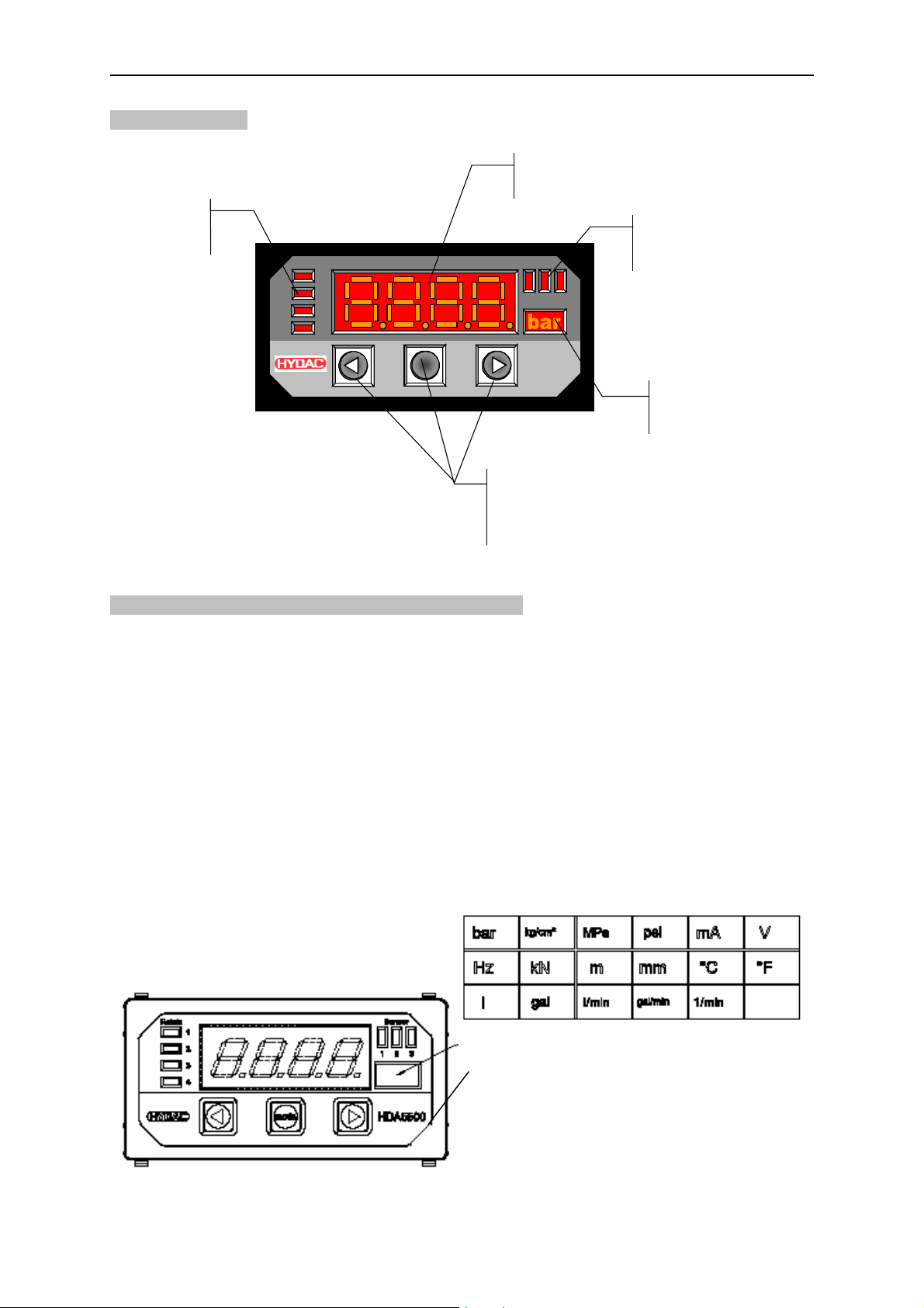
4 Operating keys
LED displays
Relais
4 digit
igital display
d
ensor
S
HDA5500
Keys for adjusting the
switching points,
switch-back points and
the menu functions
LED displays
of active
sensor
Display of
unit of measurement
or sensor 1, 2 or 3
f
5 Selection and display of the unit of measurement
The operator can select the appropriate unit label from a printed sheet and this is then
displayed with background lighting. The label can be changed at any time.
Procedure:
• Disconnect the unit from supply voltage.
• Remove the front frame of the unit by hand.
• Loosen the 4 front plate screws.
• Press lightly on the back panel of the unit to push out the front side (display section) by a
few millimetre.
• Cut the label with the required unit from the sheet supplied.
• Insert the label into the slot on the side.
• Press lightly on the front panel to push it back on.
• Screw the front plate back in place.
• Put the front frame back on.
Indication of unit using label from sheet
Front frame
- 4 -
Page 5
HDA 5500 User Manual
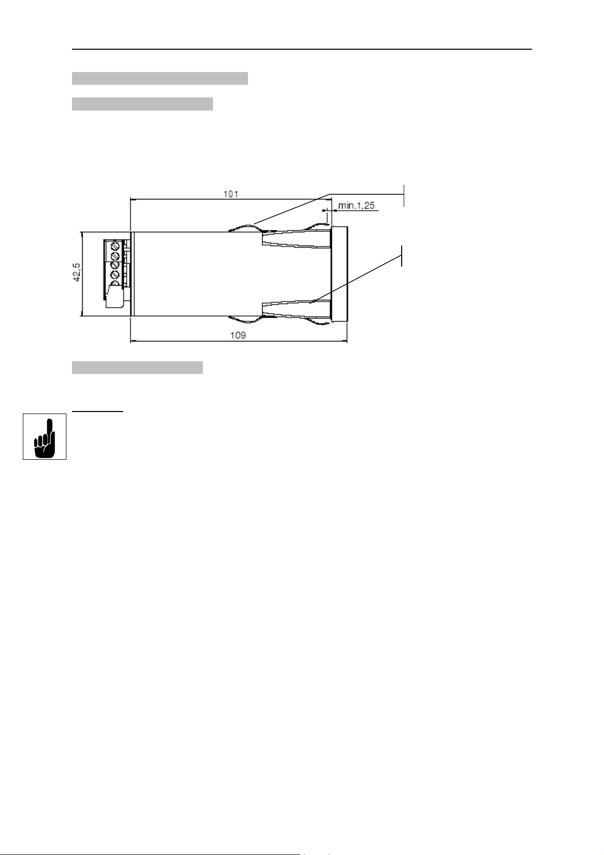
6 Installation and commissioning
6.1 Mechanical installation
The HDA 5500 is a control panel unit with a standard mounting housing with the following
measures for mounting:
• Control panel cut-out of 92 x 45 mm
• Panel thickness: at least 1.25 mm
• Mounting depth: at least 150 mm
Panel clips
Panel thickness
Clamping guides
6.2 Electrical connection
The electrical connection must be carried out by a qualified electrician in accordance with
relevant regulations (in Germany: VDE 0100).
Important:
In order to fulfil the relevant EMC standards, subject to the ambient conditions, the screening
effect of the control box must comply with the EMC standard.
Additional installation notes which, from experience, reduce the effect of electromagnetic
interference:
• Make line connections as short as possible.
• Use screened lines (e. g. LIYCY 4 x 0.5 mm²).
• The cable screening must be fitted by qualified personnel subject to the ambient condi-
tions and with the aim of suppressing interference.
• Direct proximity to interference must be avoided as far as possible.
If inductive loads are to be switched using the relays, varistors must be used on the load to
prevent high switch-off surges.
- 5 -
Page 6
HDA 5500 User Manual
12..32 VDC
85..265 VAC 50 / 60 Hz
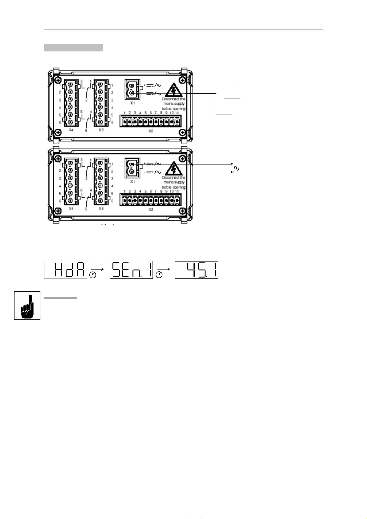
6.3 Supply voltage
The supply voltage is connected to terminal X1.
HDA 5500–X–X–DC–000
(see type code label)
HDA 5500–X–X–AC–000
(see type code label)
After switching on the supply voltage, the unit displays HdA for approximately 2 s. Then the
number of the sensor set as the primary display is shown. After a further approximately 2 s
the actual value is displayed.
2 s
2 s
Important:
Before sensors are connected, the HDA 5500 must be set appropriately.
If there is no input signal, then the following will be displayed, depending on the type of
signal:
• Starting value of the measuring range - flashing (for sensors with 4..20 mA)
• Starting value of the measuring range (for sensors with 0..10 V)
- 6 -
Page 7

HDA 5500 User Manual
7 Programming
In order to adapt the unit to a particular application, the HDA 5500 is programmed by varying
the basic settings. The basic settings are combined in a menu.
Important:
When the menu is activated, no switching operations are carried out.
7.1 Adjusting the basic settings
To change the basic settings, the menu must be activated.
Procedure for activating the menu:
• During normal operation, press the MODE key and hold down for at least 5 s.
• MEnu (Menu) is displayed.
• After approximately 2 s the display changes and the first menu point is displayed (varies
according to type).
• Press MODE until the required menu point appears in the display.
• After approximately 2 s the display changes and the actual setting is displayed.
• Use
• Press MODE again until the next required menu point appears in the display.
or to change the setting.
mode
5 s
Press Mode key and hold
down until Menu appears
Procedure for adopting and storing changes and to close the menu:
• Press MODE until the menu point End is displayed.
• After approximately 2 s the display changes and No is displayed.
• Use
• Confirm with MODE.
If the basic settings have been changed and the menu has been closed with Yes, then for
approximately 2 s ProG (Programming) is displayed when leaving the menu. The changed
settings are then saved in the HDA 5500. Afterwards the display returns to normal operation.
Important:
If no key is pressed for longer than approximately 25 s, then the menu automatically closes
down. Any changes which may have been made will not be adopted or saved.
or to change the setting to Yes.
Menu is displayed
Release mode key
mode
Press mode key until
the required menu point
is displayed
Use
the setting, then select the
next menu point
or to change
- 7 -
Page 8

HDA 5500 User Manual
7.2 Overview of basic settings menu
Menu point Setting Setting range Default setting
Primary display (PriM)
Value which is normally displayed:
Measured value sensor 1
Lowest value sensor 1
Peak value sensor 1
SEn.1
Min.1
ToP.1
SEn.1
Display filter (diSP)
Display reacts slowly to measurement variations
(display delay approximately 1.3 s).
Display reacts at standard rate to measurement
variations (display delay approximately 0.6 s).
Display reacts quickly to measurement variations
(display delay approximately 0.3 s).
Reset time (r.TiM)
Duration in seconds of for how long the last lowest / peak value
is displayed.
Input signal sensor 1 (inP.1)
0..5 V
0..10 V
4..20 mA source
SLoW
MEdi
FAST
0..3600 0
5 V
10 V
mA.r.
mA.S.
MEdi
mA.S.
4..20 mA sink
Decimal place sensor 1 (dEc.1)
No. of decimal place(s) of the display of measured value of
sensor 1
Lower limit sensor 1 (LOr.1)
Lower limit of the display range of sensor 1
Upper limit sensor 1 (Hir.1)
Upper limit of the display range of sensor 1
Background lighting for the unit label for sensor 1 (uni.1)
Lighting behind unit label is switched on when
sensor 1 value is displayed.
Lighting behind unit label is switched off when
sensor 1 value is displayed.
0..0.000 0.0
-999..9899 0
-899..9999 100.0
on
oFF
on
- 8 -
Page 9

HDA 5500 User Manual
Menu point Setting Setting range Default setting
Calibration of sensor zero point (CALi.)
The actual measurement is saved as the new zero
point. This is possible in the range +/- 2.5 % of the
display range.
is displayed if a calibration has been
carried out in the permitted range.
is displayed if a calibration has not
been possible.
The function is useful for example, if the output signal always
has an offset which should be displayed as the zero point.
Actual measured value is not to be saved.
YES
no
no
Analogue output signal (ouT.M)
4..20 mA through analogue output signal
0..10 V through analogue output signal
Software version (VErS)
Display of the software version (for reference only)
To close basic settings (End)
Basic settings menu closes.
Changed settings are saved.
Basic settings can still be altered.
MA
VoLT
YES
no
VoLT
no
- 9 -
Page 10

HDA 5500 User Manual
123
4
AGND
7
5
AGND
6
7
123
4
5
123
4
AGND
7
5
8 Connecting sensors
One analogue input for one transmitter is always available as standard.
8.1 HDA 5500 with one transmitter
Connection example for transmitter with a 4..20 mA sink as input signal,
e. g. HDA 5500-0-0-DC-000 with HDA 4445-A-100-000
(refer to chapter 16 Pin configurations):
IN1
HDA 4445-A-...
Connection example for transmitter with a 4..20 mA source as input signal,
e. g. HDA 5500-0-0-DC-000 with EDS 3446-3-0100-000
(refer to chapter 16 Pin configurations):
HDA 5500-...
Input signal sensor 1
EDS 3446-3-...
Connection example for transmitter with a 0..10 V as input signal,
e. g. HDA 5500-0-0-DC-000 with HDA 4746-B-100-000
(refer to chapter 16 Pin configurations):
HDA 4746-B-...
IN1
+12 V
IN1
HDA 5500-...
Input signal sensor 1:
HDA 5500-...
Input signal sensor 1:
- 10 -
Page 11

HDA 5500 User Manual
9 Digital display
9.1 Standard display
According to the particular type, the following list of values can be set as the primary display.
The pre-set value concerned will be continuously displayed.
• SEn.1 (measured value from sensor 1)
The displayed value corresponds to the measured value and is proportional to the input
signal of the corresponding sensor. The values are linear between the lower limit and the
upper limit.
• Min.1 (lowest value from sensor 1)
The displayed value corresponds to the lowest value which has been measured since the
supply voltage was switched on or since the last reset.
• ToP.1 (peak value from sensor 1)
The displayed value corresponds to the highest value which has been measured since
the supply voltage was switched on or since the last reset.
Notes:
• If the measured value exceeds the upper display range of the HDA 5500, then the
measured value can no longer be displayed. The upper display range flashes.
• If the measured value is below 1 % of the lower display range, then the measured value
can no longer be displayed. The lower display range flashes.
9.2 Special display
If a measured value is set as the primary display, then by pressing the
following values can be displayed separately. These values are each displayed for approximately 3 s:
• Lowest value
• Peak value
The relevant lowest and peak values are reset by pressing the
ously during normal operation. If the reset has been successful, rES (reset) is displayed to
confirm this.
and keys simultane-
or keys the
- 11 -
Page 12

HDA 5500 User Manual
Analog. Out
AGND
min
V
AGND
RL
max
= 400
Analog. Out
10 Output response
The HDA 5500 has a through analogue output which is proportional to the input signal. In
addition, depending on the model and type, without switching outputs or two or four switching
outputs are available.
10.1 Analogue output
On the analogue output a 4..20 mA or 0..10 V signal is available. This signal is proportional
to the input signal of the sensor. It’s type can be adjusted during normal operation.
10.1.1 Analogue output set to 4..20 mA
Connection example for analogue output set to 4..20 mA:
I
= 4..20 mA
ut
o
10.1.2 Analogue output set to 0..10 V
Connection example for analogue output set to 0..10 V:
= 0..10 V
out
RL
2,000
- 12 -
Page 13

HDA 5500 User Manual
10.2 Switching outputs
Not available on this type.
10.3 Connection of up to four switching outputs
Not available on this type.
11 Adjusting switching points and hystereses
Procedure for HDA 5500 without switching outputs:
• During normal operation, press mode key.
Since no switching outputs are available, noSP (no switch point) will be displayed.
• After approximately 2 s the display returns to normal operation.
Note:
If the mode key is pressed for longer than approximately 5 s, then the Basic Settings Menu
will be activated.
12 Programming enable
The unit has two types of programming enable, the operating programming enable and the
main programming enable. Both types must be enabled to change the settings.
The operating programming enable provides protection from unintentional changes to the
settings during normal operation. The operating programming enable can be altered during
operation.
The main programming enable provides general protection from changes to the settings.
The main programming enable can only be altered when the HDA 5500 is switched on.
12.1 Altering the operating programming enable
Procedure:
• During normal operation, press the
and keys simultaneously and hold down for at
least 3 s.
• OPrG (Operating Programming) is displayed.
• After approximately 2 s the display changes and the actual setting is displayed:
Free (programming enabled) or Loc (programming disabled).
• Within approx. 3 s the setting can be changed to Loc or Free by pressing
or .
• If or is not pressed for approximately 3 s or longer, then the displayed setting is
accepted. If a setting has been altered, then ProG (programming) is displayed for approximately 2 s. This means the changed setting is stored in the HDA 5500. Afterwards
the display returns to normal operation.
Displays
measured value
3 s
mode
Press both arrow
keys simultaneously
and hold down for 3 s
3 s
Display
(release
arrow keys)
2 s
Use to change setting
or
= programming enabled
FrEE
Loc
= programming disabled
mode
- 13 -
Page 14

HDA 5500 User Manual
12.2 Altering the main programming enable
The main programming enable can only be altered when switching on the HDA 5500. If the
HDA 5500 is already in operation, then the supply voltage must first be switched off or the
HDA 5500 must be disconnected from the supply voltage.
Procedure:
• When switched off, press both arrow keys simultaneously and hold down.
• Switch on or connect the supply voltage and at the same time continue to hold down the
arrow keys for at least 3 s.
• MPrG (Main Programming) is displayed.
• After approximately 2 s the display changes and the actual setting is displayed:
Free (programming enabled) or Loc (programming disabled).
• Within approximately 3 s the setting can be changed to Loc or Free by pressing
the
• If
setting is accepted. If a setting has been changed, then ProG (Programming) is displayed for approximately 2 s. This means the changed setting is stored in the HDA 5500.
Afterwards the display returns to normal operation.
or key.
or have not been pressed for approximately 3 s or longer, then the displayed
mode
Press both arrow
keys simultaneously
and hold down.
Switch on supply
voltage (hold down
keys for 3 s)
3 s
Display
(release
arrow keys)
2 s
mode
Use to change setting
or
FrEE
Loc
= programming enabled
= programming disabled
Displays
measured value
3 s
- 14 -
Page 15

HDA 5500 User Manual
13 Technical specifications
Display range
Display 4-digit 7-segment LED display, red, height of digits 14.2 mm
3 LED for active sensor
4 LED for switching relays
Display range - 999..9999 (adjustable by user)
Display units with background lighting bar, kg/cm², MPa, psi, °C, °F, l/min, mA, V, Hz, kN, m, mm, l, gal,
gal/min, 1/min, and more
Input data
Analogue signal input(s)
Measuring range(s) (up to 3 analogue inputs) adjustable: 4..20 mA, 0..5 V or 0..10 V
Accuracy class
PT100 input
Measuring range - 25..100 °C
Accuracy class
Frequency / counter input
Signal threshold 0..0.6 V = LOW
Frequency range 15 Hz .. 4 kHz
Output data
Analogue output
Accuracy of the analogue output
Rise time 70 ms
Switching outputs
Type 2 or 4 relays each with separate common supply
Switching voltage 0.1..250 VAC
Switching current 9 mA .. 2 A
Switching capacity 400 VA, 50 W (for inductive loads, use varistors)
Life expectancy of the switching contacts
Reaction time (with switching delay = 0 ms) approximately 20 ms
Setting range of the switching points 1.5..100 % of the pre-set display range
Setting range of the switching hystereses
(switch-back points)
Interface Serial interface RS232
Ambient conditions
Nominal temperature range 0 .. + 50 °C
Operating temperature range 0 .. + 50 °C
Storage temperature range - 40 .. + 80 °C
- mark
Other data
Housing Control panel housing 96 x 48 x 109 mm
Electrical connections Supply voltage: plug-in terminal block, 2 pole, RM 5.08
Supply voltage 85..265 VAC 50 / 60 Hz or
Power consumption 15 VA at 85..230 VAC, fuse protection 1 A inert
Supply of the measurement transmitter
Protection class to DIN 40050 IP 20
Reverse polarity protection of the supply
voltage, excess voltage, override protection
Weight approximately 320 g
± 0.5 % at 25 °C
± 0.5 % at 25 °C
3..24 V = HIGH
adjustable: 4..20 mA, Ohmic resistance 400 L or
0..10 V, Ohmic resistance 2 kL
± 0.5 % at 25 °C
20 million at minimum load
1 million at nominal load
0.5..99 % of the pre-set display range
Baud rate 19,200 bauds – 8 data bits – 1 start and stop bit –
no parity – no handshake
EN 50081-1 and –2 EN 50082-1 EN 61000-6-2
Control panel cut-out 92 (+0.8) x 45 (+0.6) mm
Front panel thickness 1.25.. 5 mm
Maximum installation depth 121 mm
Inputs / outputs: plug-in terminal block, 11 pole, RM 3.5
Relays: plug-in terminal block 6 pole, RM 5.08
Max. cross section of the connections 1.5 mm² for inputs / outputs
Max. cross section of the connections 2.5 mm² for supply voltage and
relays
12..32 VDC
12 ±1 % VDC max. 20 mA per analogue input
provided
- 15 -
Page 16

HDA 5500 User Manual
AC = 85..265 VAC
14 Model code HDA 5500
Order details
HDA 5 5 0 0 – X – X – X X – 0 0 0
Inputs
0 = one analogue input
1 = three analogue inputs
2 = one analogue input + frequency
input / counter function
3 = one analogue input + Pt100 input
Outputs
0 = without switching outputs
1 = two relay outputs
2 = four relay outputs
Supply voltage
DC = 12..32 VDC
Modification
000 = standard
- 16 -
Page 17

HDA 5500 User Manual
15 Unit dimensions
Control panel thickness
Control panel cut-out
- 17 -
Page 18

HDA 5500 User Manual
16 Electrical connections
HDA 5500-X-0-XC-000
HDA 5500-X-1-XC-000
HDA 5500-X-2-XC-000
Supply voltage plug X1
UNIT PIN DESCRIPTION Models
HDA 5500 – X – X – AC – 000
HDA 5500 – X – X – DC – 000 + / - Supply voltage inputs 24 VDC 1 , 2 and 3
~ / ~
X1
Supply voltage inputs 85 VAC to 265 VAC 50 / 60 Hz 1 , 2 and 3
Signals plug X2
X2
UNIT 12 3 4567891011 Models
HDA 5500 – 0 – X – XX – 000 RXD TXD DGND
HDA 5500 – 1 – X – XX – 000 RXD TXD DGND
HDA 5500 – 2 – X – XX – 000 RXD TXD DGND
HDA 5500 – 3 – X – XX – 000 RXD TXD DGND
Analogue
output
Analogue
output
Analogue
output
Analogue
output
AGND +12 V
AGND +12 V
AGND +12 V
AGND +12 V
Sensor 1
input
Sensor 1
input
Sensor 1
input
Sensor 1
input
Sensor 2
Sensor 3
input
Freq Start Stop Clear 1 , 2 and 3
Pt100 Pt100 Pt100 Pt100 1 , 2 and 3
AGND 1 , 2 and 3
input
1 , 2 and 3
Relay plugs X3 / X4
UNIT 12 3 456123456Models
HDA 5500 – X – 0 – XX – 000 1
HDA 5500 – X – 1 – XX – 000
HDA 5500 – X – 2 – XX – 000
X3 X4
N/C
N/C
R1
R1
Common
supply
R1
R1
Common
supply
R1
N/O
R1
N/O
N/C
N/C
R2
R2
Common
supply
R2
Common
supply
R2
R2
N/O
R2
N/OR3N/C
R3
Common
supply
N/O
2
R4
N/C
R4
Common
supply
N/O
R4
3
R3
- 18 -
Page 19

HDA 5500 User Manual
17 Error messages
If an error is detected, then a corresponding error message appears which must be acknowledged by pressing any key. Possible error messages are as follows:
Er.01 The switching points and hystereses have been set in such a way that the resulting
switch-back point is no longer within the permissible setting range.
Example:
Switching point is set to 180 bar, the hysteresis to 200 bar.
Action: Correct the hysteresis setting.
Er.02 The minimum difference in the given measuring ranges between lower display
range and upper display range is too low.
Examples:
Lower display range = 0.025 and upper display range = 0.075
Lower display range = 0.25 and upper display range = 0.75
Lower display range = 2.5 and upper display range = 7.5
Lower display range = 25 and upper display range = 75
Action: Correct measuring range settings as follows:
Lower display range = 0.0XX => minimum value for upper display range = 0.1XX
Lower display range = 0.XXX => minimum value for upper display range = 1.XXX
Lower display range = X.XXX => minimum value for upper display range = 1X.XX
Lower display range = XX.XX => minimum value for upper display range = 1XX.X
Er.03 The difference of the measuring values between sensor 1 and sensor 2 is outside
the measuring range.
Action: Check all the settings (programming enables, switching points, switchback points and basic settings) and correct them if necessary. If the errors occur
frequently, please contact HYDAC Service.
E.10 A data error has been detected in the saved settings. Possible causes are strong
electromagnetic interference or a component fault.
Action: Check all the settings (programming enables, switching points, switchback points and basic settings) and correct them if necessary. If the errors occur
frequently, please contact HYDAC Service.
The display shows four horizontal segments. This means that the sensor supply
voltage (+12 V, plug X2.6) is overloaded.
Action: Ensure that the above mentioned supply voltage of +12 V has not shortcircuited against AGND. Check that the maximum current has not exceeded
100 mA.
18 HYDAC Service
HYDAC Service is available for enquiries
about repairs or alterations:
Subject to technical modifications
HYDAC TECHNOLOGY GMBH
HYDAC Service
Hauptstr. 27
D-66128 Saarbrücken
Germany
Tel.: +49-(0)681-7099-237
Fax: +49-(0)681-7099-239
HYDAC ELECTRONIC GMBH
Hauptstr. 27
D-66128 Saarbrücken
Germany
Tel.: +49-(0)681-7099-0
Fax: +49-(0)681-7099-202
- 19 -
 Loading...