

Page 1
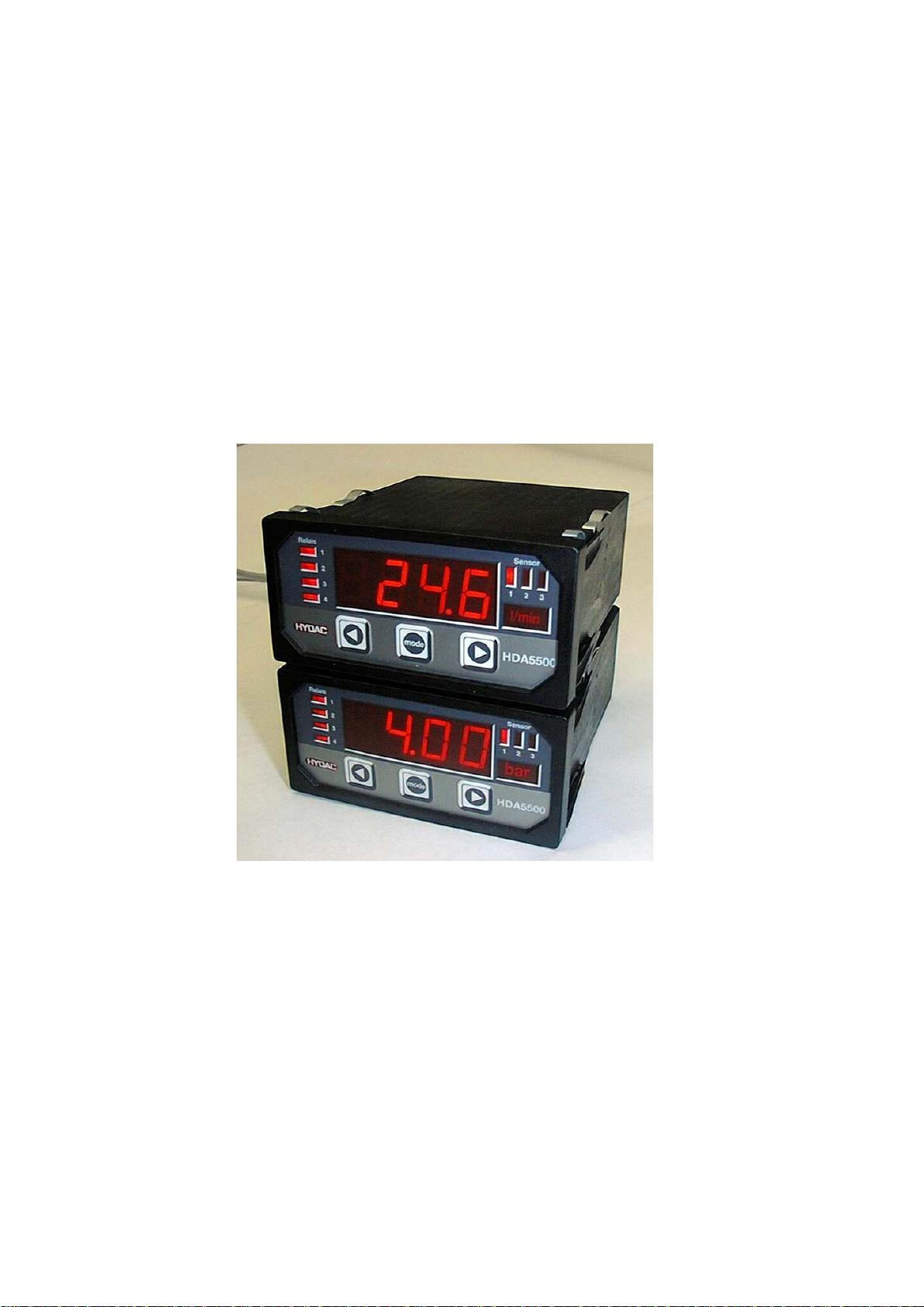
Display Unit
HDA 5500
Operator Manual
date:10.05.04
Release 4.0x
Page 2
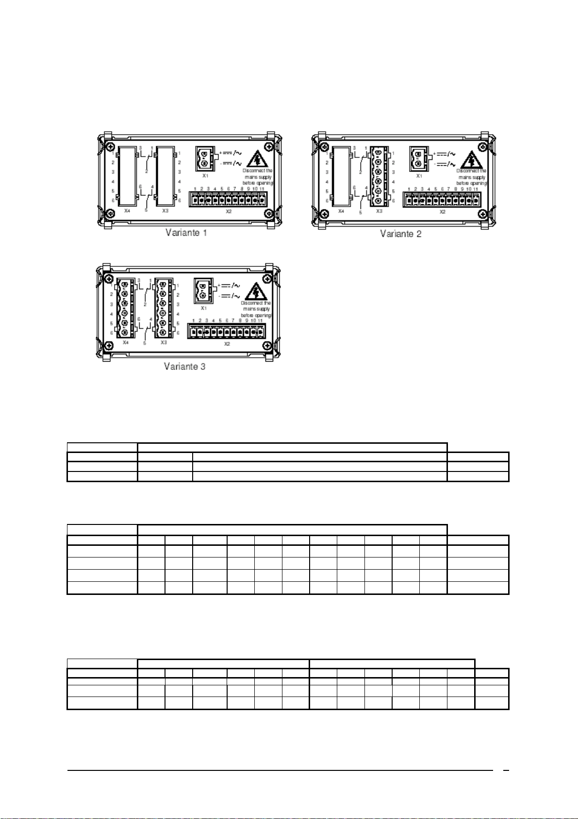
3.2.1 Pin connection
Supply voltage connector X1
~ / ~
X1
Supply voltage 85VAC bis 265VAC 50/60Hz 1 , 2 and 3
device PIN description Variante
HDA 5500 – X – X – AC – 000
HDA 5500 – X – X – DC – 000 + / - Supply voltage 24VDC 1 , 2 and 3
Signal connector X2
X2
device 12 3 4567891011 Variante
HDA 5500 – 0 – X – XX – 000 RXD TXD DGND
HDA 5500 – 1 – X – XX – 000 RXD TXD DGND
HDA 5500 – 2 – X – XX – 000 RXD TXD DGND
HDA 5500 – 3 – X – XX – 000 RXD TXD DGND
Analog
Output
Analog
Output
Analog
Output
Analog
Output
AGND +12V
AGND +12V
AGND +12V
AGND +12V
Sensor 1
Input
Sensor 1
Input
Sensor 1
Input
Sensor 1
Input
Sensor 2
Sensor 3
Input
Freq Start Stop Clear 1 , 2 and 3
Pt100 Pt100 Pt100 Pt100 1 , 2 and 3
AGND 1 , 2 and 3
Input
1 , 2 and 3
Connection of the relais
contacts X3 / X4
device 12 3 456123456Variante
HDA 5500 – X – 0 – XX – 000 1
HDA 5500 – X – 1 – XX – 000
HDA 5500 – X – 2 – XX – 000
X3 X4
R1
N/CR1Base
R1
N/CR1Base
N/O
N/O
R1
R1
R2
N/CR2BaseR2N/O
R2
N/CR2BaseR2N/OR3N/CR3BaseR3N/OR4N/CR4BaseR4N/O
2
3
1
Page 3
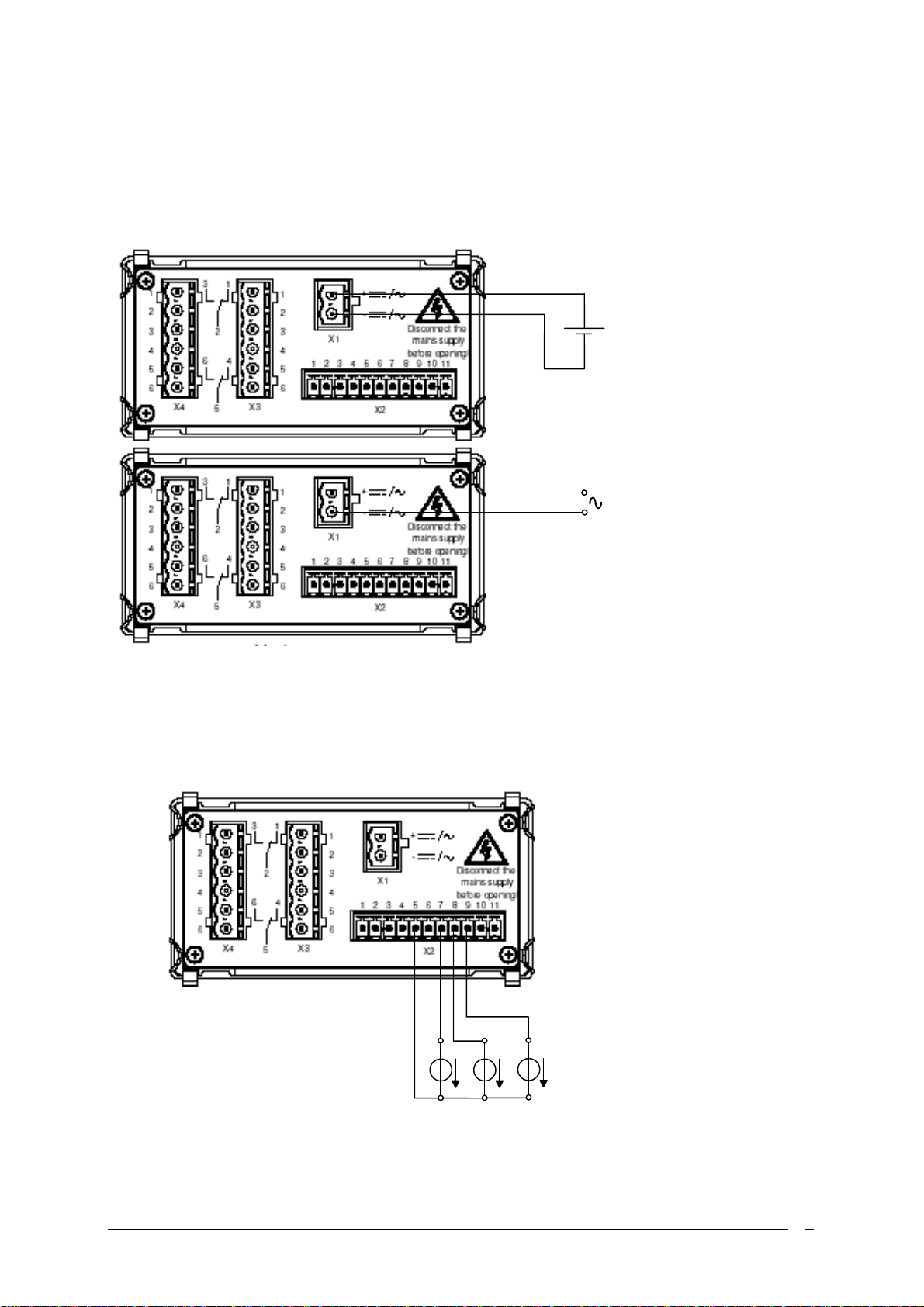
3.2.2 Connection diagramm of the HDA 5500
A
A
A
3.2.2.1 Connection of the supply voltage
12..32 V DC
–
–
–
85..265 V AC 50/60 Hz
–
–
–
3.2.2.2 Connection of the sensor with voltage signal
(IN2 and IN3 only for HDA 5500 – 1 – X – XX – XXX)
IN 1
GND
u
GND
IN 2
IN 3
u
u
GND
2
Page 4
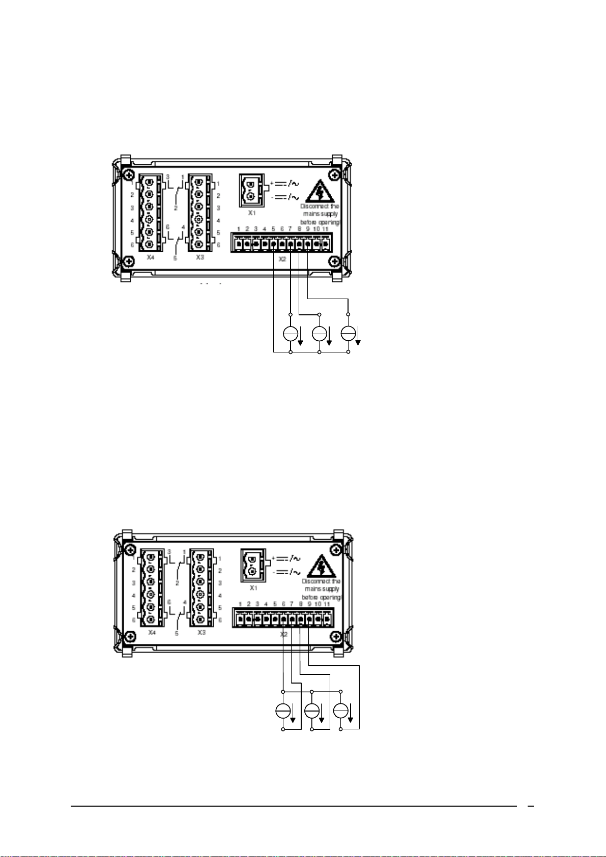
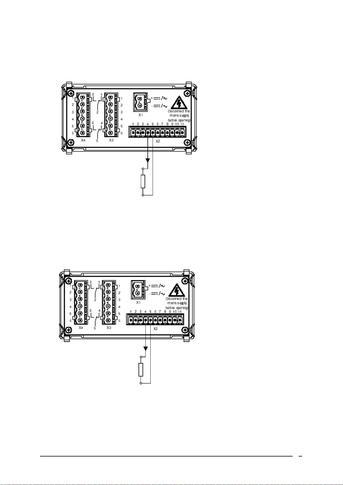
3.2.2.3 Connection of the sensor with current signal
A
A
A
(IN2 and IN3 only for HDA 5500 – 1 – X – XX – XXX)
IN 1
GND
I
GND
IN 2
IN 3
I
I
GND
3.2.2.4 Connection of the sensor with current raising signal
(IN2 and IN3 only for HDA 5500 – 1 – X – XX – XXX)
+12V
I
IN 1
I
IN 2
I
IN 3
3
Page 5
3.2.2.5 Analog output for current signal (for all devices)
A
A
A
A
Iout =
nalog. Out
=
GND
3.2.2.6 Analog output for voltage signal (for all devices)
nalog. Out
Vout =
GND
>=
4
Page 6
3.2.2.7 Seriel interface (all devices)
r
Settings: 19200 Baud – 8 Data bits – 1 Startbit – 1 Stopbit – no
Parity Bit and no handshake.
TXD RXD DGND
control device
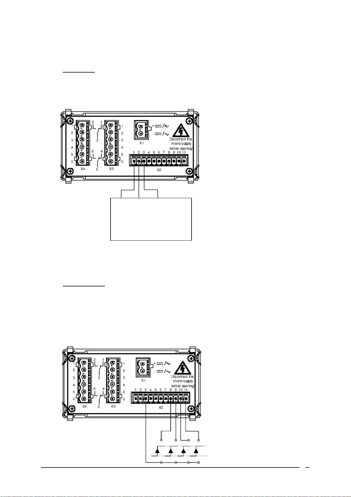
3.2.2.8 Digital Inputs – Frequency / counter function
(HDA 5500 – 2 – X – XX – XXX)
description: Freq., Start, Stop and Clear, are 4 digital Inputs. All
those signals are active triggered to raising edge. The maximum
amplitude is 24 VDC.
Freq.
Start
Stop
Clea
24VDCmax
0V
DGND
5
Page 7

3.2.2.8 Pt100 Input (HDA 5500 – 3 – X – XX – XXX)
Pt100
3.2.2.9 Connection of the relais
(SP1 and SP2 for HDA 5500 –X– 1 – XX – XXX and HDA 5500 –X– 2 – XX – XXX
SP3 and SP4 for HDA 5500 –X– 2 – XX – XXX)
SP4 Öf.
SP4 Sc.
SP3 Öf.
SP3 Sc.
SP2 Öf.
SP2 Sc.
SP1 N/C
SP1 N/O
6
Page 8

4. Front unit of HDA 5500
relais-LED
fhighlighted
for active SP
Relais
1
2
3
4
MODE
MODE
4-digit
display
Sensor LED
highlighted for
Sensor
123
active sensor
HDA5500
soft keys to set
sitching and switchback points,
and changing basic settings
display of
physical unit
for sensor 1
7
Page 9

7.2 BASIC SETTINGS
display Setting
Switch Point source 1 (SS 1)
Switching mode SP 1 (SM 1)
function
Sensor 1 is aktivated to SS 1
Sensor 2 is aktivated to SS 1
Sensor 3 is aktivated to SS 1
Difference value (Sensor 1 – Sensor 2)
is aktivated to SS 1
SP 1 operates with adjustable
SP and hysteresis function
SP 1 operates in window
Setting
range
Sen1
Sen2
Sen3
Diff
SP/ Win SP HDA 5500 - X - 1 - XX - XXX
Presetting device
HDA 5500 - 1 - 1 - XX - XXX
Sen1
HDA 5500 - 1 - 2 - XX - XXX
HDA 5500 - 2 - 1 - XX - XXX
HDA 5500 - 2 - 2 - XX - XXX
HDA 5500 - 3 - 1 - XX - XXX
HDA 5500 - 3 - 2 - XX - XXX
HDA 5500 - 1 - 1 - XX - XXX
HDA 5500 - 1 - 2 - XX - XXX
HDA 5500 - X - 2 - XX - XXX
Switching direction SP 1 (Sd 1)
normaly open
normaly closed
Switch on delay SP 1 (Ton 1)
Delay time to aktivate the switch point,
after reaching the pressure for SP 1
Switch off delay SP 1 (Toff 1)
Delay time to switch off the switch point,
after reaching the switch back point for SP 1
Switch Point source SP 2 (SS 2)
Sensor 1 is activated to SP 2
Sensor 2 is activated to SP 2
Sensor 3 is activated to SP 2
ON/ OFF ON HDA 5500 - X - 1 - XX - XXX
0.00..99.99s 0 HDA 5500 - X - 1 - XX - XXX
0.00..99.99s 0 HDA 5500 - X - 1 - XX - XXX
Sen1
Sen2
Sen3
Diff
Sen.1
HDA 5500 - X - 2 - XX - XXX
HDA 5500 - X - 2 - XX - XXX
HDA 5500 - X - 2 - XX - XXX
HDA 5500 - 1 - 1 - XX - XXX
HDA 5500 - 1 - 2 - XX - XXX
HDA 5500 - 2 - 1 - XX - XXX
HDA 5500 - 2 - 2 - XX - XXX
HDA 5500 - 3 - 1 - XX - XXX
HDA 5500 - 3 - 2 - XX - XXX
HDA 5500 - 1 - 1 - XX - XXX
HDA 5500 - 1 - 2 - XX - XXX
Difference value (Sensor 1 – Sensor 2)
is aktivated to SP 2
8
Page 10

display Setting
Switching mode SP 2 (SM 2)
SP 2 operates with adjustable
SP and hysteresis function
Setting
range
SP/ Win SP HDA 5500 - X - 1 - XX - XXX
Presetting device
HDA 5500 - X - 2 - XX - XXX
function
SP 2 operates in window
Switching direction SP 1 (Sd 1)
normaly open
normaly closed
Switch on delay SP 2 (Ton 2)
Delay time to aktivate the switch point,
after reaching the pressure for SP 2
Switch off delay SP 2 (Toff 2)
Delay time to switch off the switch point,
after reaching the switch back point for SP 2
Switch Point source SP 3 (SS 3)
Sensor 1 is activated to SP 3
Sensor 2 is activated to SP 3
Sensor 3 is activated to SP 3
ON/ OFF ON HDA 5500 - X - 1 - XX - XXX
0.00..99.99s 0 HDA 5500 - X - 1 - XX - XXX
0.00..99.99s 0 HDA 5500 - X - 1 - XX - XXX
Sen1
Sen2
Sen3
Diff
Sen.1
HDA 5500 - X - 2 - XX - XXX
HDA 5500 - X - 2 - XX - XXX
HDA 5500 - X - 2 - XX - XXX
HDA 5500 - 1 - 2 - XX - XXX
HDA 5500 - 2 - 2 - XX - XXX
HDA 5500 - 3 - 2 - XX - XXX
HDA 5500 - 1 - 2 - XX - XXX
is activated to SP 3
Difference value (Sensor 1 – Sensor 2)
Switching mode SP 3 (SM 3)
SP 3 operates with adjustable
SP and hysteresis function
SP 3 operates in window
function
Switching direction SP 3 (Sd 3)
normaly open
normaly closed
Switch on delay SP 3 (Ton 3)
Delay time to aktivate the switch point,
after reaching the pressure for SP 3
Switch off delay SP 3 (Toff 3)
Delay time to switch off the switch point,
after reaching the switch back point for SP 3
SP/ Win SP HDA 5500 - X - 2 - XX - XXX
ON/ OFF ON HDA 5500 - X - 2 - XX - XXX
0.00..99.99s 0 HDA 5500 - X - 2 - XX - XXX
0.00..99.99s 0 HDA 5500 - X - 2 - XX - XXX
9
Page 11

display Setting
Switch Point source SP 4 (SS 4)
Sensor 1 is activated to SP 4
Sensor 2 is activated to SP 4
Setting
range
Sen1
Sen2
Presetting device
Sen.1 HDA 5500 - 1 - 2 - XX - XXX
HDA 5500 - 2 - 2 - XX - XXX
HDA 5500 - 3 - 2 - XX - XXX
Sensor 3 is activated to SP 4
Difference value (Sensor 1 – Sensor 2)
is activated to SP 4
Switching mode SP 4 (SM 4)
SP 3 operates with adjustable
SP and hysteresis function
SP 3 operates in window function
Switching direction SP 4 (Sd 4)
normaly open
normaly closed
Switch on delay SP 4 (Ton 4)
Delay time to aktivate the switch point,
after reaching the pressure for SP 4
Switch off delay SP 4 (Toff 4)
Delay time to switch off the switch point,
after reaching the switch back point for SP 4
Sen3
Diff
SP/ Win SP HDA 5500 - X - 2 - XX - XXX
ON/ OFF ON HDA 5500 - X - 2 - XX - XXX
0.00..99.99s 0 HDA 5500 - X - 2 - XX - XXX
0.00..99.99s 0 HDA 5500 - X - 2 - XX - XXX
HDA 5500 - 1 - 2 - XX - XXX
Primary display (Primary)
Display value which should remain permanently
in the display:
current value Sensor 1
Minimum value Sensor 1
maximum value Sensor 1
current value Sensor 2
Minimum valu Sensor 2
Maximum value Sensor 2
Sen.1
Min.1
Top.1
Sen.2
Min.2
Top.2
Sen.1 for all devices
HDA 5500 - 1 - X - XX - XXX
HDA 5500 - 2 - X - XX - XXX
HDA 5500 - 3 - X - XX - XXX
10
Page 12

display Setting
Setting
range
Presetting device
current value Sensor 3
Minimum value Sensor 3
maximum value Sensor 3
Difference value (Sensor 1 – Sensor 2)
Minimmum difference value (Sensor 1
- Sensor 2)
Maximum difference value (Sensor 1 -
Sensor 2)
or
or
Displayfilter (Display)
Display reacts slowly to pressure
variations
SP 1 or SP 2
SP 3 or SP 4
Sen.3
Min.3
Top.3
Diff
Min.d
Top.d
SP.1
SP.2
SP.3
SP.4
SLOW/
MEDI/
FAST
HDA 5500 - 1 - X - XX - XXX
HDA 5500 - 1 - X - XX - XXX
HDA 5500 - 2 - X - XX - XXX
HDA 5500 - 3 - X - XX - XXX
HDA 5500 - X - 1 - XX - XXX
HDA 5500 - X - 2 - XX - XXX
HDA 5500 - X - 2 - XX - XXX
MEDI For all devices
Display reacts at standard rate to
pressure variations
Display reacts quickly to pressure
variations
Reset time (RTIM)
Indicates how long the last minimum or peak
pressure is shown on the display
Sensor 1 input mode of signal
Sensor 1, input 0..5V
Sensor 1, input 0..10V
Sensor 1, input 4..20mA, source
Sensor 1, input 4..20mA, drain
0..3600s 0 For all devices
5V
10V
mA.r.
mA.S.
10V for all devices
11
Page 13

display Setting
Decimal places Sensor 1
number of decimal places for sensor 1 shown in the
display
Lower display range (Low Range) Sensor 1
Lower display range limit
Setting
range
0..0.000 0.0 For all devices
-999..9899 0.0 For all devices
Presetting device
Upper display range (High Range) Sensor 1
Upper display limit
LED – light indicator Sensor 1
ON
OFF
Sensor 2 input mode of signal
Sensor 2, input 0..5V
Sensor 2, input 0..10V
Sensor 2, input 4..20mA, source
Sensor 2, input 4..20mA, drain
Decimal places Sensor 2
number of decimal places for sensor 1 shown in the
display
Lower display range (Low Range) Sensor 2
Lower display range limit
-899..9999 10.0 For all devices
On
Off
5V
10V
mA.r.
mA.S.
0..0.000 0.0 HDA 5500 - 1 - X - XX - XXX
-999..9899 0.0 HDA 5500 - 1 - X - XX - XXX
On For all devices
10V HDA 5500 - 1 - X - XX - XXX
HDA 5500 - 3 - X - XX - XXX
HDA 5500 - 3 - X - XX - XXX
Upper display range (High Range) Sensor 2
Upper display limit
LED – light indicator Sensor 2
ON
OFF
Sensor 3 input mode of signal
Sensor 3, input 0..5V
Sensor 3, input 0..10V
Sensor 3, input 4..20mA, source
Sensor 3, input 4..20mA, drain
Decimal places Sensor 2
number of decimal places for sensor 1 shown in the
display
-899..9999 10.0 HDA 5500 - 1 - X - XX - XXX
On
Off
5V
10V
mA.r.
mA.S.
0..0.000 0.0 HDA 5500 - 1 - X - XX - XXX
On HDA 5500 - 1 - X - XX - XXX
10V HDA 5500 - 1 - X - XX - XXX
HDA 5500 - 3 - X - XX - XXX
HDA 5500 - 3 - X - XX - XXX
12
Page 14

display Setting
Lower display range (Low Range) Sensor 2
Lower display range limit
Setting
range
-999..9899 0.0 HDA 5500 - 1 - X - XX - XXX
Presetting device
Upper display range (High Range) Sensor 2
Upper display limit
LED – light indicator Sensor 2
ON
OFF
decimal place for correction factor
(only availible with frequency/counter function)
correction factor (frequency/counter function)
Flow measurements:
Settings:
f = (Fakt.) * Qmax / 60 (Hz)
Qmax : maximum flow of turbine in l/min
Fakt. : correktion factor of the turbine (Impulse/l).
decimal place to set in dEcF.
Display:
Flow = (f x 60) / FacT in l/min
Frequency measurements:
To display the frequency in Hz, follow settings must
be done:
dEc.F = 0 and FAcT. = 60
Counter function:
Settings :
decF = 0 und FacT = 1
-899..9999 10.0 HDA 5500 - 1 - X - XX - XXX
On
Off
0..0.000 0.0 HDA 5500 - 2 - X - XX - XXX
0..9999 0.0 HDA 5500 - 2 - X - XX - XXX
On HDA 5500 - 1 - X - XX - XXX
Calibration of sensor zero point (Calibrate)
The actual pressure is saved as the new zero
point.This is possible in the range +/-2,5% of the
unit’s nominal pressure.
appears in the display when a calibration is carried
out in the permissible range, otherwise
is displayed.
This function is useful, for example, if there is always
a residual pressure in the system which should be
displayed as 0 bar.
Warning:
Following a zero point adjustment, for example, on a
600 bar unit, a pressure of up to 15 bar will be
displayed as 0 bar. Before any work is carried out on
the hydraulic system, ensure that the system is depressurised.
YES/ NO NO For all devices
13
Page 15

display Setting
Assign the analog output to the sensor
Assign sensor 1 to the analog output
Assign sensor 2 to the analog output
Setting
range
Sen1
Sen2
Presetting device
HDA 5500 - 1 - X - XX - XXX
Sen1
HDA 5500 - 2 - X - XX - XXX
HDA 5500 - 3 - X - XX - XXX
Assign sensor 3 to the analog output
Assign the difference value
(sensor 1 – sensor 2) to the analog
output
Analog output signal
4..20mA output signal
0..10V output signal
Version number (Version)
actual software version (only to display)
End of BASIC SETTINGS (End)
Leave the Basic Settings
Continue Basic Settings
Sen3
Diff
MAMP/
VOLT
YES/ NO NO
MAMP For all devices
HDA 5500 - 1 - X - XX - XXX
For all devices
For all devices
If the basic settings have been altered, ProG appears briefly when quitting the basic settings menu,
and then the selected display value is shown in the primary display.
14
Page 16

HDA 5500 Order Code
HDA 5 5 0 0 – X – X – XX – 0 0 0
Inputs
0 = 1 Analog Ínput
1 = 3 Analog Inputs
2 = 1 Analog Input + Frequency
Input / Counter function
3 = 1 Analog Input + PT 100 - Input
Outputs
0 = no switching outputs
1 = 2 relais switching outputs
2 = 4 relais switching outputs
Supply voltage
AC = 85..265 VAC
DC = 12..32 VDC
Modifikation
000 = Standard
15
Page 17

Press and hold the mode button for 5 seconds to change menu settings.
Power down/up the unit while pressing both arrow keys to Free/Lock the settings.
Gauge Connections for standard 4-20ma transducer output
HDA 4475-A-XXXX-XXX HDA5500 connector X2
1-------------------7 (Input1)
2-------------------5 (AGND)
 Loading...