

Page 1
Stand: 16.12.2013 HYDAC ELECTRONIC GMBH Mat. Nr.: 669687 D/E/F
Druckmessumformer
Pressure Transmitter
Transmetteur de Pression
HDA 4100
Absolutdruck
Absolute pressure
Pression absolue
HDA 4300
Relativdruck
Relative pressure
Pression relative
Page 2

2 HDA 4100 / HDA 4300
Stand: 16.12.2013 HYDAC ELECTRONIC GMBH Mat. Nr.: 669687 D/E/F
1
ALLGEMEINES ............................................................................................. 3
2
MONTAGE .................................................................................................... 3
3
ABMESSUNGEN ........................................................................................... 4
4
ELEKTRISCHES ZUBEHÖR ......................................................................... 5
5
ANSCHLUSSBILDER .................................................................................... 6
6
ANSCHLUSSBELEGUNG ............................................................................. 6
7
BESTELLANGABEN ..................................................................................... 7
8
TECHNISCHE DATEN .................................................................................. 8
1
GENERAL ..................................................................................................... 9
2
ASSEMBLY ................................................................................................... 9
3
DIMENSIONS .............................................................................................. 10
4
ELECTRICAL ACCESSORIES ................................................................... 11
5
CONNECTION DIAGRAMS ........................................................................ 12
6
PIN CONNECTIONS ................................................................................... 12
7
MODEL CODE ............................................................................................ 13
8
TECHNICAL DATA ...................................................................................... 14
1
GENERALITES ........................................................................................... 15
2
MONTAGE .................................................................................................. 15
3
ENCOMBREMENTS ................................................................................... 16
4
ACCESSOIRES RACCORDEMENT ÉLECTRIQUE ................................... 17
5
RACCORDEMENT ELECTRIQUE .............................................................. 18
6
BRANCHEMENTS ...................................................................................... 18
7
CODE DE COMMANDE .............................................................................. 19
8
CARACTERISTIQUES TECHINQUES ....................................................... 20
Page 3
HDA 4100 / HDA 4300 3
Stand: 16.12.2013 HYDAC ELECTRONIC GMBH Mat. Nr.: 669687 D/E/F
1 ALLGEMEINES
Falls Sie Fragen bezüglich der technischen Daten oder Eignung für Ihre Anwendungen haben,
wenden Sie sich bitte an unseren technischen Vertrieb. Die Druckmessumformer der Serie HDA 4000
werden einzeln auf rechnergesteuerten Prüfplätzen abgeglichen und einem Endtest unterzogen. Sie sind
wartungsfrei und sollten beim Einsatz innerhalb der Spezifikationen (siehe Technische Daten) einwandfrei
arbeiten. Falls trotzdem Fehler auftreten, wenden Sie sich bitte an den HYDAC-Service. Fremdeingriffe
in das Gerät führen zum Erlöschen jeglicher Gewährleistungsansprüche.
2 MONTAGE
Die Druckmessumformer können über den Gewindeanschluss direkt an der Hydraulikanlage montiert
werden. Um in kritischen Anwendungsfällen (z.B. starke Vibrationen oder Schläge) einer mechanischen
Zerstörung vorzubeugen, empfehlen wir das Gerät mittels einer Schelle mit Elastomereinsatz zu
befestigen, sowie den Hydraulikanschluss über eine Minimessleitung zu entkoppeln.
Die empfohlene Einbaulage für hydraulische Anwendungen ist senkrecht mit dem Druckanschluss nach
oben, für pneumatische Anwendungen senkrecht mit dem Druckanschluss nach unten.
Das Anzugsdrehmoment für den G 1/4 A Gewindeanschluss beträgt ca. 20 Nm und für den G1/2
Gewindeanschluss 45 Nm.
Der elektrische Anschluss sollte von einem Fachmann nach den jeweiligen Landesvorschriften
durchgeführt werden (VDE 0100 in Deutschland).
Die Druckmessumformer der Serie HDA 4000 tragen das - Zeichen. Eine Konformitätserklärung ist auf
Anfrage erhältlich. Die EMV-Normen: EN 61000-6-1, EN 61000-6-2, EN 61000-6-3 und EN 61000-6-4
werden erfüllt. Die Forderungen der Normen werden nur bei ordnungsgemäßer und fachmännischer
Erdung des Druckmessumformergehäuses erreicht.
Beim Einschrauben in einen Hydraulikblock ist es ausreichend, wenn der Block über das Hydrauliksystem
geerdet ist. Bei einer Schlauchmontage muss das Gehäuse separat geerdet werden.
Zusätzliche Montagehinweise die erfahrungsgemäß den Einfluss elektromagnetischer Störungen
reduzieren:
• Möglichst kurze Leitungsverbindungen herstellen
• Leitungen mit Schirm verwenden (z.B. LIYCY 4 x 0,5 mm²)
• Der Kabelschirm ist in Abhängigkeit der Umgebungsbedingungen fachmännisch und zum Zweck
der Störunterdrückung einzusetzen
• Direkte Nähe zu Verbindungsleitungen von Leistungsverbrauchern oder störenden Elektro- oder
Elektronikgeräten ist möglichst zu vermeiden
Page 4
4 HDA 4100 / HDA 4300
Stand: 16.12.2013 HYDAC ELECTRONIC GMBH Mat. Nr.: 669687 D/E/F
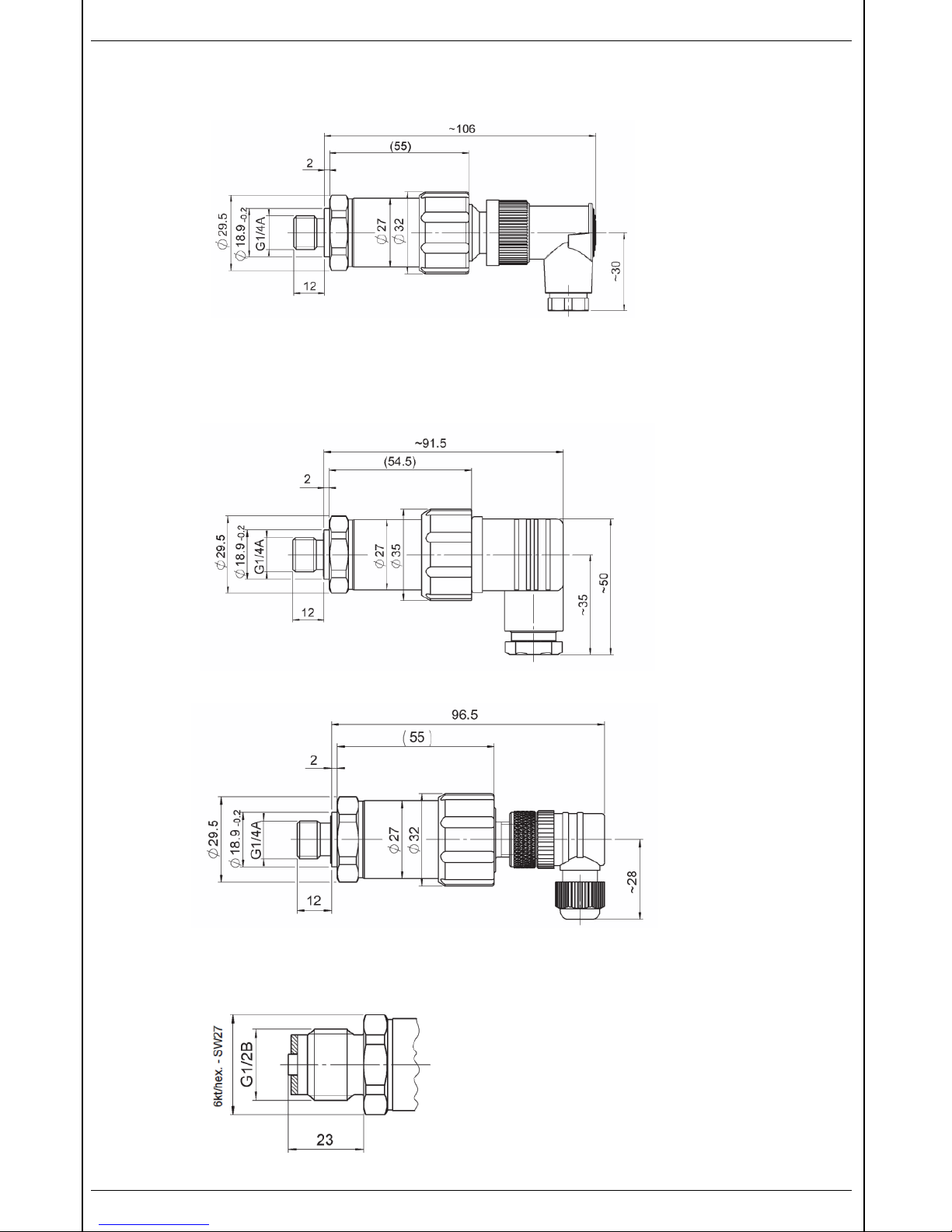
3 ABMESSUNGEN
HDA 4144 / 4344 Abbildung mit ZBE 03
Maß mit Winkeldose ZBE 03: 106 mm
Maß mit Kupplungsdose ZBE 02: ≈ 125 mm
HDA 4145 / 4345 Abbildung mit ZBE 01
HDA 4146 / 4346 Abbildung mit ZBE 06
G1/2 B DIN-EN 837
Page 5
HDA 4100 / HDA 4300 5
Stand: 16.12.2013 HYDAC ELECTRONIC GMBH Mat. Nr.: 669687 D/E/F
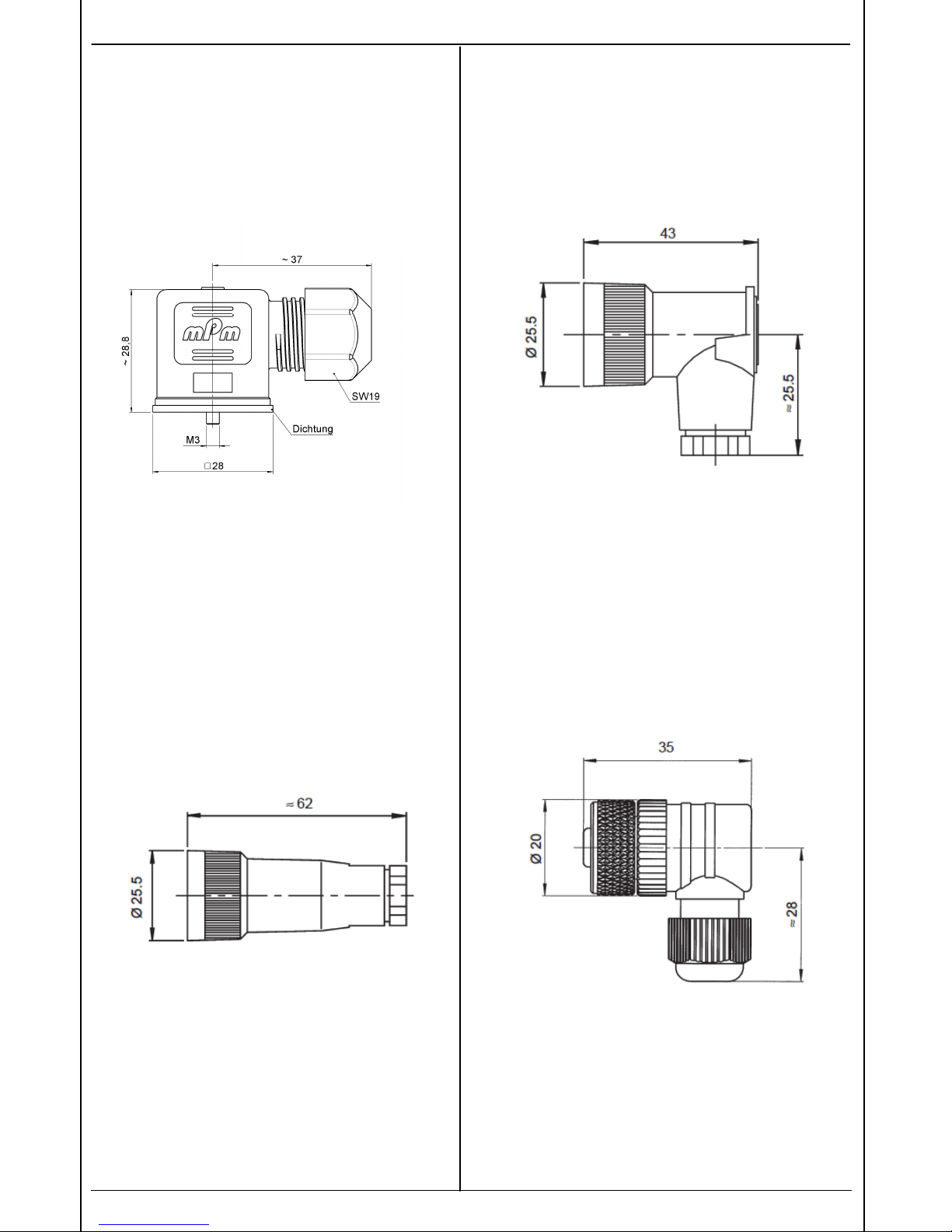
4 ELEKTRISCHES ZUBEHÖR
ZBE 01 Kupplungsdose 3-pol.+PE, abgewinkelt
EN 175301-803/ISO 4400(DIN 43650)
ZBE 02 Kupplungsdose 4-pol.
Binder Serie 714M18
ZBE 03 Kupplungsdose 4-pol., abgewinkelt
Binder Serie 714M18
ZBE 06 Kupplungsdose 4.polig, abgewinkelt
M12x1
Page 6
6 HDA 4100 / HDA 4300
Stand: 16.12.2013 HYDAC ELECTRONIC GMBH Mat. Nr.: 669687 D/E/F
5 ANSCHLUSSBILDER
2-Leiter 4 .. 20 mA
R
Lmax
= (UB – 8 V) / 0,02 A [Ω]
3-Leiter 0 .. 10 V
R
Lmin
= 2 kΩ
Anmerkung:
Der Lastwiderstand RL ergibt sich aus dem intern
im Auswertegerät befindlichen Meßwiderstand
und dem Leitungswiderstand der
Anschlußleitung.
6 ANSCHLUSSBELEGUNG
Binder Serie 714 M18
HDA 41X4
HDA 43X4
Pin 1
Pin 2
Pin 3
Pin 4
HDA 41X4
-A
HDA 43X4-A
n.c. Signal+ Signal- n.c.
HDA 41X4
-B
HDA 43X4-B
+UB Signal 0v n.c.
EN175301-803 (DIN 43650)
HDA 41X5
HDA 43X5
Pin 1
Pin 2
Pin 3
Pin 4
HDA 41X5
-A
HDA 43X5-A
Signal+ Signal- n.c. Gehäuse
HDA 41X5
-B
HDA 43X5-B
+UB 0v Signal Gehäuse
M12x1
HDA 41X6
HDA 43X6
Pin 1
Pin 2
Pin 3
Pin 4
HDA 41X6
-A
HDA 43X6-A
Signal+ n.c. Signal- n.c.
HDA 41X6
-B
HDA 43X6-B
+UB n.c. 0v Signal
Page 7

HDA 4100 / HDA 4300 7
Stand: 16.12.2013 HYDAC ELECTRONIC GMBH Mat. Nr.: 669687 D/E/F
7 BESTELLANGABEN
HDA 4 X X X – X – XXXX – 000 – X 1
Ausführung (Druckart)
1 = Absolutdruck
3 = Relativdruck
Anschlussart, mechanisch
1 = G1/2 B DIN EN 837 Außengewinde
4 = G1/4 A DIN 3852 Außengewinde
Anschlussart, elektrisch
4 = 4-pol. Binderstecker 714 M18 (ohne Kupplungsdose)
5 = Gerätestecker 3-pol.+ PE, EN 175301-803 / ISO 4400
(inklusive Kupplungsdose ZBE 01)
6 = 4-pol. Gerätestecker M12x1 (ohne Kupplungsdose)
Signaltechnik
A = 2 Leiter, 4 .. 20 mA
B = 3 Leiter, 0 .. 10 V
Druckbereich in bar
HDA 41XX: 01,0; 01,6; 02,5 Absolutdruck
HDA 43XX: 01,0; 02,5; 04,0; 06,0; 0010; 0016; 0025; 0040;
0001 (-1 .. 1); 0005 (-1 .. 5); 0009 (-1 .. 9 bar) Relativdruck
Modifikationsnummer
000 = Standard
Dichtungsmaterial
F = FPM Dichtung (z.B. für Hydrauliköle)
E = EPDM Dichtung (z.B. für Kältemittel)
Anschlussmaterial (medienberührend)
1 = Edelstahl
Anmerkung:
Bei Geräten mit anderer Modifikationsnummer ist das Typenschild bzw.
die mitgelieferte technische Änderungsbeschreibung zu beachten.
Page 8

8 HDA 4100 / HDA 4300
Stand: 16.12.2013 HYDAC ELECTRONIC GMBH Mat. Nr.: 669687 D/E/F
8 TECHNISCHE DATEN
Anmerkung: FS (Full Scale) = bezogen auf den vollen Messbereich. Sonderausführungen auf Anfrage
1)
-25°C mit FPM- oder EPDM Dichtung, -40°C auf Anfrage
Die Angaben in diesem Prospekt beziehen sich auf die beschriebenen Betriebsbedingungen und Einsatzfälle. Bei abweichenden Einsatzfällen
und/oder Betriebsbedingungen wenden Sie sich bitte an die entsprechende Fachabteilung. Technische Änderungen sind vorbehalten.
Eingangskenngrößen
HDA 4
100
(absolut)
HDA 43
00 (relativ)
Messbereiche bar
1 1,6 2,5
1 2,5 4 6 10 16 25 40
-1 .. 1 -1 .. 5 -1 .. 9
Überlastbereich bar 3 8 8 3 8 12 20 32 50 80 120
3 20 32
Berstdruck bar 5 12 12 5 12 18 30 48 75 120 180
5 30 48
Mechanischer Anschluss G ¼ A DIN 3852; G1/2 B DIN-EN 837
Anzugsdrehmoment 20 Nm (G1/4)
45 Nm (G ½)
Medienberührende Teile Keramik, Edelstahl
Dichtung: Kupfer (G1/2),
FPM/EPDM-Dichtung
Keramik, Edelstahl
Dichtung: Kupfer (G1/2),
FPM/EPDM-Dichtung
Ausgangsgrößen
Kennlinienabweichung bei
Grenzpunkteinstellung nach
DIN16086
(Genauigkeitsklasse)
Max.
Typ.
≤ ±1 % FS
≤ ±0,5 % FS
≤ ±1 % FS
≤ ±0,5 % FS
Kennlinienabweichung bei
Kleinstwerteinstellung
Max.
Typ.
≤ ±0,5 % FS
≤ ±0,25 % FS
≤ ±0,5 % FS
≤ ±0,25 % FS
Temperaturkompensation NP
Max.
Typ.
≤ ±0,03 %/ °C
≤ ±0,02 %/ °C
≤ ±0,03 %/ °C
≤ ±0,02 %/ °C
Temperaturkompensation Spanne
Max.
Typ.
≤ ±0,03 %/ °C
≤ ±0,02 %/ °C
≤ ±0,03 %/ °C
≤ ±0,02 %/ °C
Linearität bei
Grenzpunkteinstellung
nach DIN 16086
Max.
Typ.
≤ ±0,5 % FS
≤ ±0,25 % FS
≤ ±0,5 % FS
≤ ±0,25 % FS
Hysterese
Max. ≤ ±0,4 % FS ≤ ±0,4 % FS
Wiederholbarkeit ≤ ±0,1 % FS
≤ ±0,1 % FS
Anstiegszeit ca. 1 ms
ca. 1 ms
Langzeitdrift ≤ ±0,3 % FS typ. / Jahr
≤ ±0,3 % FS typ. / Jahr
Umgebungsbedingungen
Kompensierter Temperaturbereich -25 .. +85 °C -25 .. +85 °C
Betriebstemperaturbereich
-25 .. +85 °C -25 .. +85 °C
Lagertemperaturbereich -40 .. +100 °C -40 .. +100 °C
Mediumstemperaturbereich
1)
-40 .. +100 °C / -25 .. +100°C -40 .. +100 °C / -25 .. +100°C
-Zeichen EN 61000-6-1/2/3/4
EN 61000-6-1
-Zeichen Zertifikat-Nr. E318391 Zertifikat-Nr. E318391
Vibrationsbeständigkeit nach
DIN EN 60068-2-6 bei 10 .. 500 Hz
≤ 20 g
(196,2 m/s²)
≤ 20 g
(196,2 m/s²)
Schutzart nach DIN 40050 IP 65 (Binder 714M18)
IP 67 (EN 175301-803 u.
M12x1, bei Verwendung
einer IP 67
Kupplungsdose)
IP 65 (Binder 714M18)
IP 67 (EN 175301-803 u. M12x1, bei
Verwendung einer IP 67
Kupplungsdose)
Sonstige Größen
Versorgungsspannung
Versorgungsspannung
Bei Einsatz gemäß ULSpezifikation
8 .. 30 V DC 2-Leiter
12 .. 30 V DC 3-Leiter
-limited energy- gemäß
9.3 UL 61010; Class 2;
UL 1310/1585; LPS UL 60950
8 .. 30 V DC 2-Leiter
12 .. 30 V DC 3-Leiter
-limited energy- gemäß
9.3 UL 61010; Class 2;
UL 1310/1585; LPS UL 60950
Restwelligkeit Versorgunssp. ≤ 5 % ≤ 5 %
Stromaufnahme 3-Leiter ≤ 25 mA
≤ 25 mA
Verpolungsschutz der
Versorgungsspg.,
Überspannungs-,
Übersteuerungsschutz,
Lastkurzschlussfestigkeit
vorhanden vorhanden
Lebensdauer 10 Mio. Lastwechsel 10 Mio. Lastwechsel
Gewicht ca. 150 g ca. 150 g
Page 9

HDA 4100 / HDA 4300 9
Stand: 16.12.2013 HYDAC ELECTRONIC GMBH Mat. Nr.: 669687 D/E/F
1 GENERAL
If you have any queries regarding technical details or the suitability of the pressure transmitter for your
application please contact our sales/technical department. The HDA 4000 series of transmitters are
individually calibrated on computercontrolled test rigs and subjected to a final test. The pressure
transmitters are maintenance-free and should operate perfectly when used according to the specifications
(see technical details). If faults do nonetheless arise, please contact HYDAC Service. Interference by
anybody other than HYDAC personnel will invalidate all warranty claims.
2 ASSEMBLY
The pressure transmitter can be fitted directly to the hydraulic system via the threaded connection. For
mechanical decoupling in the case of strong vibrations or knocks we recommend that the pressure
transmitter be mounted by means of a clamp with rubber insert and that the hydraulic connection be made
via a Minimess hose.
The recommended mounting position is vertical with the pressure connection pointing upwards in hydraulic
applications and vertical with the pressure connection pointing downwards in pneumatic applications.
The tightening torque for the G¼ male thread should be approx. 20 Nm, and approx. 45 Nm for G½ male
thread.
The electrical connection should be carried out by a qualified electrician according to the relevant
regulations of the country concerned (i.e. VDE 0100 in Germany).
The pressure transmitters of the series HDA 4000 carry the mark. A declaration of conformity is
available on request. Conformance with EMC standards: EN 61000-6-1, EN 61000-6-2, EN 61000-6-3, EN
6100-6-4.The requirements of the standards are fulfilled only if the pressure transmitter housing is earthed
correctly by qualified personnel.
When fitting the pressure transmitter into a hydraulic block it is sufficient if the block is earthed via the
hydraulic system. In the case of hose-mounting, the housing must be earthed separately.
Additional assembly notes which, from experience, reduce the effect of electromagnetic interference:
• Make line connections as short as possible
• Use screened cables (e.g. LIYCY 4x0.5 mm²)
• The cable screening must be fitted by qualified personnel subject to the ambient conditions and with
the aim of suppressing interference
• Direct proximity to connecting lines of user units or electrical or electronic units causing interference
must be avoided as far as possible
Page 10

10 HDA 4100 / HDA 4300
Stand: 16.12.2013 HYDAC ELECTRONIC GMBH Mat. Nr.: 669687 D/E/F
3 DIMENSIONS
HDA 4144 / 4344, shown with ZBE 03
Dimension with right-angled plug ZBE 03: 106 mm
Dimension with straight plug ZBE 02: ≈ 125 mm
HDA 4145 / 4345, shown with ZBE 01
HDA 4146 / 4346, shown with ZBE 06
G1/2 B DIN EN 837
Page 11

HDA 4100 / HDA 4300 11
Stand: 16.12.2013 HYDAC ELECTRONIC GMBH Mat. Nr.: 669687 D/E/F
4 ELECTRICAL ACCESSORIES
ZBE 01 Right-angled connector, 3-pole + earth
EN 175301-803/ISO 4400 (DIN 43650)
ZBE 02 Binder connector,
4-pole series 714 M18
ZBE 03 Binder connector, right angled,
4-pole series 714 M18
ZBE 06 M12x1 connector, right angled,
4-pole
sealing gasket
Page 12

12 HDA 4100 / HDA 4300
Stand: 16.12.2013 HYDAC ELECTRONIC GMBH Mat. Nr.: 669687 D/E/F
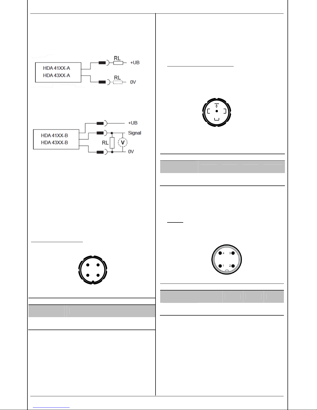
5 CONNECTION DIAGRAMS
Two-conductor 4 .. 20 mA
R
Lmax
= (UB – 8 V) / 0,02 A [Ω]
Three-conductor 0 .. 10 V
R
Lmin
= 2 kΩ
Note:
The load resistance RL is the sum of the
measuring resistance inside the evaluation unit
and the line resistance of the connection line.
6 PIN CONNECTIONS
Binder series 714 M18
HDA 41X4
HDA 43X4
Pin 1
Pin 2
Pin 3
Pin 4
HDA 41X4
-A
HDA 43X4-A
n.c. Signal+ Signal- n.c.
HDA 41X4
-B
HDA 43X4-B
+UB Signal 0v n.c.
EN175301-803 (DIN 43650)
HDA 41X5
HDA 43X5
Pin 1
Pin 2
Pin 3
Pin 4
HDA 41X5
-A
HDA 43X5-A
Signal+ Signal- n.c. Gehäuse
HDA 41X5
-B
HDA 43X5-B
+UB 0v Signal Gehäuse
M12x1
HDA 41X6
HDA 43X6
Pin 1
Pin 2
Pin 3
Pin 4
HDA 41X6
-A
HDA 43X6-A
Signal+ n.c. Signal- n.c.
HDA 41X6
-B
HDA 43X6-B
+UB frei 0v Signal
Page 13

HDA 4100 / HDA 4300 13
Stand: 16.12.2013 HYDAC ELECTRONIC GMBH Mat. Nr.: 669687 D/E/F
7 MODEL CODE
HDA 4 X X X – X – XXXX – 000 – X 1
Type (type of pressure)
1 = Absolute pressure
3 = Relative pressure
Type of connection, mechanical
1 = G1/2 B DIN EN 837 male thread
4 = G1/4 A DIN 3852 male thread
Type of connection, electrical
4 = 4-pole Binder 714M18 (without connector)
5 = 3 pole + earth, EN 175301-803 / DIN 4400
(connector ZBE01 supplied)
6 = 4-pole M12x1 (without connector)
Signal technology
A = 2-conductor, 4 .. 20 mA
B = 3-conductor, 0 .. 10 V
Pressure ranges in bar
HDA 41XX: 01,0; 01,6; 02,5 absolute pressure
HDA 43XX: 01,0; 02,5; 04,0; 06,0; 0010; 0016; 0025; 0040;
0001 (-1 .. 1); 0005 (-1 .. 5); 0009 (-1 .. 9 bar) relative pressure
Modification number
000 = Standard
Sealing materail
F = FPM seal (e.g. for hydraulic oils)
E = EPDM seal (e.g. for refrigerants)
Material, mechanical connection (in contact with medium)
1 = stainless steel
Note:
On units with other modification numbers, please read the label or the technical amendment details
supplied with the number.
Page 14

14 HDA 4100 / HDA 4300
Stand: 16.12.2013 HYDAC ELECTRONIC GMBH Mat. Nr.: 669687 D/E/F
8 TECHNICAL DATA
Note: FS (Full Scale) = relative to the full measuring range. Special models on request.
1)
-25°C with FPM oe EPDM seal, -40°C on request
The information in this brochure relates to the operating conditions and applications described.
For applications or operating conditions not described, please contact the relevant technical department.
Subject to technical modifications.
Input data
HDA 4100
(absolut)
HDA 4300
(relative)
Measuring ranges bar
1 1,6 2,5
1 2,5 4 6 10 16 25 40
-1 .. 1 -1 .. 5 -1 .. 9
Overload pressure bar 3 8 8 3 8 12 20 32 50 80 120
3 20 32
Burst pressure bar 5 12 12 5 12 18 30 48 75 120 180
5 30 48
Mechanical connection G ¼ A DIN 3852; G1/2 B DIN-EN 837
Torque value 20 Nm (G1/4)
45 Nm (G ½)
Parts in contact with media Ceramic, stainless steel
Seal: copper (G1/2),
FPM/EPDM-seal
Ceramic, stainless steel
Seal: copper (G1/2),
FPM/EPDM-seal
Output data
Curve deviation at max.
setting to DIN 16086
(accuracy class)
Max.
Typ.
≤ ±1 %FS
≤ ±0,5 %FS
≤ ±1 %FS
≤ ±0,5 %FS
Curve deviation at
min. setting
Max.
Typ.
≤ ±0,5 %FS
≤ ±0,25 %FS
≤ ±0,5 %FS
≤ ±0,25 %FS
Temperature compensation zero
point
Max.
Typ.
≤ ±0,03 %/ °C
≤ ±0,02 %/ °C
≤ ±0,03 %/ °C
≤ ±0,02 %/ °C
Temperature compenstion over
range
Max.
Typ.
≤ ±0,03 %/ °C
≤ ±0,02 %/ °C
≤ ±0,03 %/ °C
≤ ±0,02 %/ °C
Linearity at
max. setting
to DIN 16086
Max.
Typ.
≤ ±0,5 %FS
≤ ±0,25 %FS
≤ ±0,5 %FS
≤ ±0,25 %FS
Hysteresis
Max. ≤ ±0,4 %FS ≤ ±0,4 %FS
Repeatability ≤ ±0,1 %FS
≤ ±0,1 %FS
Rise time ca. 1 ms
ca. 1 ms
Long-term drift ≤ ±0,3 %FS typ. / year
≤ ±0,3 %FS typ. / year
Ambient conditions
Compensated temperature range -25 .. +85 °C -25 .. +85 °C
Operating temperature range
-25 .. +85 °C -25 .. +85 °C
Storage temperature range -40 .. +100 °C -40 .. +100 °C
Fluid temperature range
1)
-40 .. +100 °C/ -25 .. 100°C -40 .. +100 °C/ -25 .. 100°C
-mark EN 61000-6-1 / 2 / 3 / 4
-Zeichen Zertifikat-Nr. E318391 Zertifikat-Nr. E318391
Vibration resistance to
DIN EN 60068-2-6 at 10 .. 500 Hz
≤ 20 g
(196,2 m/s²)
≤ 20 g
(196,2 m/s²)
Protection class to IEC 60529 IP 65 (Binder 714M18)
IP 67( for male EN175301-803 and
M12x1, when IP 67 connector is used)
Other data
Supply voltage
For use acc.to UL spec.
8 .. 30 V 2-conductor
12 .. 30 V 3-conductor
-limited energy- according to
9.3 UL 61010; Class 2;
UL 1310/1585; LPS UL 60950
Residual ripple supply voltage ≤ 5 % ≤ 5 %
Current consumption 3-conductor ≤ 25 mA ≤ 25 mA
Reverse polarity protection of the
supply voltage, excess voltage,
override and short circuit
protection
provided provided
Life expectancy 10 milion load cycles 10 milion load cycles
Weight Approx. 145 g Approx. 145 g
Page 15

HDA 4100 / HDA 4300 15
Stand: 16.12.2013 HYDAC ELECTRONIC GMBH Mat. Nr.: 669687 D/E/F
1 GENERALITES
Chaque transmetteur de pression de la série HDA 4000 est étalonné et soumis à un test final. C'est
pourquoi nous garantissons que l'appareil livré ne possède aucun défaut et correspond aux spécifications
techniques. Si l'appareil devait toutefois présenter un dysfonctionnement, veuillez le renvoyer à l'usine avec
une description du défaut. La garantie n'est plus applicable dès lors que le matériel a été ouvert par une
personne non habilitée à cet effet. Si vous aviez des questions concernant les données techniques ou
d'adaptation de l'appareil pour votre application, veuillez consulter notre service technique.
2 MONTAGE
Le transmetteur de pression peut être monté directement sur une installation hydraulique. En cas
d'utilisation dans des situations extrêmes (fortes vibrations ou chocs violents), nous conseillons de fixer le
transmetteur à l'aide d'un collier avec garniture élastomère et d'équiper la partie filetée mécanique d'un
raccord MINIMESS.
Pour les applications hydrauliques, nous préconisons un montage vertical avec une orientation du raccord
de pression vers le haut et, pour les applications pneumatiques, un montage vertical également mais avec
orientation du raccord de pression vers le bas.
Le couple de serrage du raccord G ¼ A mâle est d’environ 20 Nm. 45 Nm pour raccord G½ mâle.
Le raccordement électrique doit être effectué par un spécialiste selon les normes en vigueur dans le pays
concerné (exemple : VDE 0100 en Allemagne).
Les transmetteurs de pression de la série HDA 4000 portent le -sigle . Un certificat de conformité peut
être délivré sur demande. Les normes en vigueur sont : EN 61000-6-1, EN 61000-6-2, EN 61000-6-3 et EN
61000-6-4. Les exigences des normes sont remplies dès lors que la mise à la terre du corps du
transmetteur de pression a été effectuée correctement.
Lors du montage du transmetteur de pression dans un bloc foré, il suffit que le bloc soit relié à la terre par
le système hydraulique. En cas de montage sur flexible, la mise à la terre s'effectue séparément.
Mesures de montage complémentaires permettant de réduire l'influence des perturbations
électromagnétiques:
• Ne prévoir, si possible, que des raccordements courts ;
• Utiliser des câbles blindés (par ex. LIYCY 4 x 0,5 mm²) ;
• L'utilisation du câble blindé se fait en fonction de l'environnement. Il est utilisé de façon à diminuer
les perturbations ;
• Eviter, si possible, de placer à proximité des raccordements des appareils électriques ou
électroniques.
Page 16

16 HDA 4100 / HDA 4300
Stand: 16.12.2013 HYDAC ELECTRONIC GMBH Mat. Nr.: 669687 D/E/F
3 ENCOMBREMENTS
HDA 4144 / 4344, avec ZBE 03
Dimension avec connecteur coudé ZBE 03: 106 mm
Dimension avec connecteur droit ZBE 02: ≈ 125 mm
HDA 4145 / 4345, avec ZBE 01
HDA 4146 / 4346, avec ZBE 06
G1/2 B DIN EN 837
Page 17

HDA 4100 / HDA 4300 17
Stand: 16.12.2013 HYDAC ELECTRONIC GMBH Mat. Nr.: 669687 D/E/F
4 ACCESSOIRES RACCORDEMENT
ÉLECTRIQUE
ZBE 01 Connecteur coudé 3 pôles + terre
EN 175301-803/ISO 4400(DIN 43650)
ZBE 02 Connecteur droit
4 pôles BINDER, série 714M18
ZBE 03 Connecteur coudé
4 pôles BINDER , série 714M18
ZBE 06 Connecteur coudé
M12x1, 4 pôles
Page 18

18 HDA 4100 / HDA 4300
Stand: 16.12.2013 HYDAC ELECTRONIC GMBH Mat. Nr.: 669687 D/E/F
5 RACCORDEMENT ELECTRIQUE
Bipolaire 4 .. 20 mA
R
Lmax
= (UB – 8 V) / 0,02 A [Ω]
Tripolaire 0 .. 10 V
R
Lmin
= 2 kΩ
Remarque:
La résistance de charge résulte de la somme de
la résistance de mesure, incorporée dans le
récepteur, avec celle de la résistivité du câble de
liaison.
6 BRANCHEMENTS
Binder connecteur 714M18
HDA 41X4
HDA 43X4
Pin 1
Pin 2
Pin 3
Pin 4
HDA 41X4
-A
HDA 43X4-A
n.c. Signal+ Signal- n.c.
HDA 41X4
-B
HDA 43X4-B
+UB Signal 0v n.c.
EN175301-803 (DIN 43650)
HDA 41X5
HDA 43X5
Pin 1
Pin 2
Pin 3
Pin 4
HDA 41X5
-A
HDA 43X5-A
Signal+ Signal- n.c. Gehäuse
HDA 41X5
-B
HDA 43X5-B
+UB 0v Signal Gehäuse
M12x1
HDA 41X6
HDA 43X6
Pin 1
Pin 2
Pin 3
Pin 4
HDA 41X6
-A
HDA 43X6-A
Signal+ n.c. Signal- n.c.
HDA 41X6
-B
HDA 43X6-B
+UB frei 0v Signal
Page 19

HDA 4100 / HDA 4300 19
Stand: 16.12.2013 HYDAC ELECTRONIC GMBH Mat. Nr.: 669687 D/E/F
7 CODE DE COMMANDE
HDA 4 X X X – X – XXXX – 000 – X 1
Exécution (technologie)
1 = Pression absolue
3 = Pression relative
Raccordement mécanique
1 = G1/2 B DIN EN 837 mâle
4 = G1/4 A DIN 3852 mâle
Raccordement électrique
4 = Embase 4 pôles BINDER 714M18 (livré sans connecteur)
5 = Connecteur 3 pôles + Terre EN 175301-803 / ISO 4400
(livré avec connecteur ZBE 01)
6 = 4 pôles connecteur M12x1
Signal
A = 2 fils, 4 .. 20 mA
B = 3 fils, 0 .. 10 V
Plage de pression en bar
HDA 41XX: 01,0; 01,6 ; 02,5 pression absolue
HDA 43XX: 01,0; 02,5; 04,0; 06,0; 0010; 0016; 0025; 0040;
0001 (-1 .. 1); 0005 (-1 .. 5); 0009 (-1 .. 9 bar) pression relative
Indice de modification
000 = Standard
Matériau des joints
F = joint FPM (p. ex. pour huiles hydrauliques
E = joint EPDM (p. ex. pour fluids de refroidissement)
Matériau de raccordement (en contact avec le fluide)
1 = acier inoxydable
Attention:
Pour les appareils avec d'autres indices de modification, veuillez respecter la plaque signalétique ou le
descriptive technique.
Page 20

20 HDA 4100 / HDA 4300
Stand: 16.12.2013 HYDAC ELECTRONIC GMBH Mat. Nr.: 669687 D/E/F
8 CARACTERISTIQUES TECHINQUES
Remarque: FS (Full Scale) = se base sur toute la plage de mesure. Autres plages de mesure dur demande.
1)
-25°C avec FPM ou EPDM joint, -40°C sur demande
Les données de ce prospectus se réfèrent aux conditions de fonctionnement et d'utilisation décrites.
Pour des conditions d'utilisation et de fonctionnement différentes, veuillez vous adresser au service technique compétent. Sous réserve de
modifications techniques.
Caractéristiques d'entrée
HDA 4100 (absolue) HDA 4300 (relative)
Plages de mesure bar
1 1,6 2,5
1 2,5 4 6 10 16 25 40
-1 .. 1 -1 .. 5 -1 .. 9
Plages de surcharge bar 3 8 8 3 8 12 20 32 50 80 120
3 20 32
Pression d‘éclatement bar 5 12 12 5 12 18 30 48 75 120 180
5 30 48
Raccordement mécanique G ¼ A DIN 3852; G1/2 B DIN-EN 837
Couple de serrage 20 Nm (G1/4)
45 Nm (G ½)
Matériaux en contact avec fluide céramique, acier inox joint:
cuivre (G1/2),
FPM/EPDM
céramique, acier inox joint:
cuivre (G1/2),
FPM/EPDM
Caractéristiques de sortie
Dérive de précision/droite
passant par les extrémités de
réglage d'après DIN16086
(classe de précision)
Max.
Typ.
≤ ±1 %FS
≤ ±0,5 %FS
≤ ±1 %FS
≤ ±0,5 %FS
Dérive de précision par rapport
à la meilleure droite (B.F.S.L.)
Max.
Typ.
≤ ±0,5 %FS
≤ ±0,25 %FS
≤ ±0,5 %FS
≤ ±0,25 %FS
Coefficient de température
au point zéro
Max.
Typ.
≤ ±0,03 %/ °C
≤ ±0,02 %/ °C
≤ ±0,03 %/ °C
≤ ±0,02 %/ °C
Coefficient de température
sur la sensibilité
Max.
Typ.
≤ ±0,03 %/ °C
≤ ±0,02 %/ °C
≤ ±0,03 %/ °C
≤ ±0,02 %/ °C
Linéarité par rapport au maximum
de la droite passant par les
extrémités
de réglages d'après DIN 16086
Max.
Typ.
≤ ±0,5 %FS
≤ ±0,25 %FS
≤ ±0,5 %FS
≤ ±0,25 %FS
Hystérésis
Max. ≤ ±0,4 %FS ≤ ±0,4 %FS
Reproductibilité ≤ ±0,1 %FS
≤ ±0,1 %FS
Temps de réponse env. 1 ms
env. 1 ms
Dérive dans le temps ≤ ±0,3 %FS typ. / an
≤ ±0,3 %FS typ. / an
Caractéristiques de
l'environnement
Plage de température compensée -25 .. +85 °C -25 .. +85 °C
Plage de température d'utilisation -25 .. +85 °C -25 .. +85 °C
Plage de température de
stockage
-40 .. +100 °C -40 .. +100 °C
Plage de température du fluide
1)
-40 .. +100 °C/ -25 .. 100°C -40 .. +100 °C/ -25 .. 100°C
Sigle EN 61000-6-1 / 2 / 3 / 4
-Zeichen Zertifikat-Nr. E318391 Zertifikat-Nr. E318391
Compatibilité électromagnétique
Résistance aux vibrations
suivant IEC 68-2-6 à 10 ..500Hz
≤ 20 g
(196,2 m/s²)
≤ 20 g
(196,2 m/s²)
Indice de protection selon DIN
40050
IP 65 (Binder 714 M18)
IP 67 ( EN 175301-803 et M12x1 lors l‘utilisation d’un connecteur IP 67)
Autres caractéristiques
Tension d'alimentation
Pour utilization selon
specification UL
8 .. 30 V pour bipolaire
12 .. 30 V pour tripolaire
-limited energy- gemäß
9.3 UL 61010; Class 2;
UL 1310/1585; LPS UL 60950
Oscillation résiduelle de la
tension d'alimentation
≤ 5 % ≤ 5 %
Consommation courant pour
tripolaire
≤ 25 mA
≤ 25 mA
Protection contre l'inversion de la
polarité de la tension d'alimentation,
contre la surtension et la saturation;
résistance à la charge et aux courtscircuits
disponible disponible
Durée de vie 10 Mio. cycles 10 Mio. cycles
Masse env. 145 g env. 145 g
 Loading...