

Page 1
Stand: 20.03.2018 HYDAC ELECTRONIC GMBH Mat. Nr.: 669723
Bedienungsanleitung
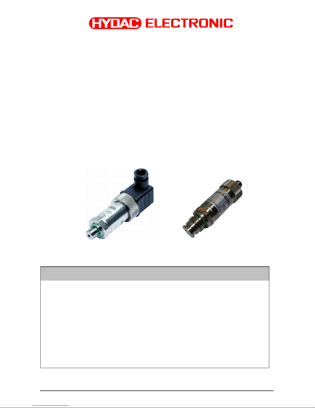
Druckmessumformer Serie HDA 4000
Eigensicher, staubgeschütztes Gehäuse,
nicht funkend
mit ATEX-Zulassung
(Original-Bedienungsanleitung)
Operating Instructions
Pressure Transmitter Series HDA 4000
Intrinsically safe, dustprotected enclosure,
non-sparking
with ATEX Approval
(translation of the original instructions)
Schutzklassen und Einsatzbereiche / Protection types and zones:
ATEX
I M1 Ex ia I Ma
II 1G Ex ia IIC T6 Ga
II 1/2 G Ex ia IIC T6 Ga/Gb
II 2 G EX ia IIC T6 Gb
II 1D Ex ia IIIC T85°C Da
II 1D Ex ta IIIC T80/T90/T100°C T
500
90/100/110°C Da
II 2D Ex tb IIIC T80/T90/T100°C Db
II 3G Ex nA IIC T6, T5, T4 Gc
II 3G Ex ic IIC T6, T5, T4 Gc
II 3D Ex tc IIIC T80/T90/T100°C Dc
II 3D Ex ic IIIC T80/T90/T100°C Dc
Zertifikat/Certificate: KEMA 05ATEX1016 X
KEMA 05ATEX1016X
Page 2

HDA 4000 eigensichere Stromkreise, Schutz durch Gehäuse, ATEX Seite 2 von 26
Stand: 20.03.2018 HYDAC ELECTRONIC GMBH Mat. Nr.: 669723
Inhaltsverzeichnis
1 Allgemeines ....................................................................................................... 3
2 Funktion ............................................................................................................. 3
3 Montage und Inbetriebnahme .......................................................................... 3
4 Wichtige Hinweise für die Installation ............................................................. 4
4.1 Installationshinweise für Geräte mit 1/2 “ NPT Conduit .............................. 4
4.2 Installationshinweise für Geräte mit Schlagschutz ..................................... 5
5 Sicherheitshinweise ......................................................................................... 6
6 Technische Daten ............................................................................................. 7
6.1 HDA 4100 / HDA 4300 ..................................................................................... 7
6.2 HDA 4400 / HDA 4700 ...................................................................................... 8
7 Typenschlüssel zur Identifikation des gelieferten Gerätes ......................... 10
7.1 Standard .......................................................................................................... 10
7.1.1 Typenschlüssel HDA 4100 / HDA 4300 ...................................................... 10
7.1.2 Typenschlüssel HDA 4400 / HDA 4700 ...................................................... 11
7.2 Typenschlüssel mit frontbündiger Membran .................................................... 12
7.2.1 Typenschlüssel HDA 4300 mit frontbündiger Membran .............................. 12
7.2.2 Typenschlüssel HDA 4400 / HDA 4700 mit frontbündiger Membran .......... 13
7.3 Auswertetabelle (Protection concept): Zuordnung der Schutzklassen und
Einsatzbereiche .................................................................................................... 14
8 Seriennummer ................................................................................................. 14
9 Anschlussbelegung ........................................................................................ 14
10 Geräteabmessungen ...................................................................................... 15
10.1 Mechanische Anschlussvarianten : ........................................................... 15
10.2 Elektrische Anschlussvarianten : ............................................................... 16
11 Zertifikate ......................................................................................................... 18
11.1 ATEX .............................................................................................................. 18
12 Konformitätserklärung ................................................................................... 25
Page 3

HDA 4000 eigensichere Stromkreise, Schutz durch Gehäuse, ATEX Seite 3 von 26
Stand: 20.03.2018 HYDAC ELECTRONIC GMBH Mat. Nr.: 669723
1 Allgemeines
Falls Sie Fragen bezüglich der technischen Daten oder Eignung für Ihre Anwendungen haben,
wenden Sie sich bitte an unseren technischen Vertrieb. Die Druckmessumformer der Serie
HDA 4000 werden auf rechnergesteuerten Prüfplätzen abgeglichen und einem Endtest
unterzogen. Sie sind wartungsfrei und sollten beim Einsatz innerhalb der Spezifikationen (siehe
Technische Daten) einwandfrei arbeiten. Falls trotzdem Fehler auftreten, wenden Sie sich bitte an
den HYDAC-Service. Fremdeingriffe in das Gerät führen zum Erlöschen jeglicher
Gewährleistungsansprüche sowie der ATEX -Zulassung.
2 Funktion
Das vom Sensor gemessene Drucksignal wird in ein dem Druck proportionales, analoges 4..20 mA
Signal umgewandelt. Der elektrische Anschluss erfolgt über einen Steckverbinder oder eine fest
angeschlossene Leitung.
3 Montage und Inbetriebnahme
Die Druckmessumformer können auf Prozess-Seite direkt über den Gewindeanschluss montiert
werden. Speziell bei Geräten mit frontbündiger (außenliegender) Membran ist bei der Montage
darauf zu achten, dass die Membrane während der Montage nicht beschädigt wird.
Um in kritischen Anwendungsfällen (z.B. starke Vibrationen oder Schläge) einer mechanischen
Zerstörung vorzubeugen, empfehlen wir das Gerät mittels einer Schelle mit Elastomereinsatz zu
befestigen, sowie den Hydraulikanschluss über eine Minimessleitung zu entkoppeln.
Anzugsdrehmoment siehe Abmessungen.
Druckmessumformer mit einem Nenndruck ≤ 100 bar (≤ 1500 psi) besitzen einen Druckausgleich
zum Umgebungsdruck. Hierzu befindet sich unter der Steckerbefestigung eine kleine Bohrung.
Diese ist von innen mit einer speziellen Membrane abgedeckt, die verhindert, dass Feuchtigkeit
von außen in das Gerät eindringen kann. Um eine Verstopfung der Bohrung zu verhindern, sollte
bei feuchter und staubhaltiger Umgebung die Montage daher waagerecht oder senkrecht mit dem
Druckanschluss nach unten erfolgen.
Bei Druckmessumformern mit einem Nenndruck von ≤ 100 bar (≤ 1500 psi) und einem
½“ Conduit elektrischen Anschluss ist der Druckausgleich bei Einzeladern mittels einer kurzen
Entlüftungslitze realisiert, bei Mantelkabel mittels einem im Kabel integrierten Entlüftungsschlauch.
Es ist sicherzustellen, dass die Entlüftung nur im Nicht-Ex-Bereich erfolgt.
Die Installation muss von einem Fachmann nach den jeweiligen Landesvorschriften zu potentiell
explosionsgefährdeten Umgebungen durchgeführt werden (z.B. IEC / EN 60079-14).
Die Druckmessumformer der Serie HDA 4000 tragen das
- Zeichen. Die Konformitätserklärung
befindet sich im Anhang.
Die Forderungen der Normen (siehe techn. Daten) werden nur bei ordnungsgemäßer und
fachmännischer Erdung des Druckmessumformergehäuses mittels des Prozessanschlusses oder
dem ½ NPT Conduit erreicht. Sofern eine grün/gelbe Ader vorhanden ist, darf diese zusätzlich,
aber nicht zur alleinigen Erdung verwendet werden. Bei Schlauchmontage des
Druckmessumformers muss das Gehäuse separat geerdet werden.
Die zugehörigen eigensicheren Geräte (z.B. Zenerbarrieren) sind ebenfalls zu erden. Ein
Potentialausgleich entlang des eigensicheren Stromkreises ist in der Ausführungsvariante N
(Isolationsspannung <= 50 VAC) erforderlich.
Bei der Serie HDA 4000 in der Ausführungsform H (Isolationsspannung ≤ 500 VAC) darf die
Kabellänge zum Druckmessumformer maximal 30m betragen (Überspannungsschutz nach DIN
EN 61000-6-2). Wenn die Kabellänge 30m überschreitet, muss der Überspannungsschutz
kundenseitig sichergestellt werden.
Page 4
HDA 4000 eigensichere Stromkreise, Schutz durch Gehäuse, ATEX Seite 4 von 26
Stand: 20.03.2018 HYDAC ELECTRONIC GMBH Mat. Nr.: 669723
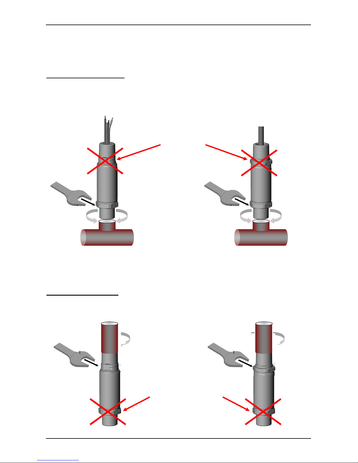
4 Wichtige Hinweise für die Installation
4.1 Installationshinweise für Geräte mit 1/2 “ NPT Conduit
Mechanische Installation
Für die Montage des Prozessanschlusses darf nur die Schlüsselfläche an der
Prozessanschlussseite des Druckmessumformers verwendet werden.
Elektrische Installation
Die Schlüsselfläche an der Seite des elektrischen Anschlusses am ½ NPT Conduit dient nur zum
Fixieren des Druckmessumformers bei der Conduit-Installation.
Nicht zum Einschrauben in die
Hydraulikleitung verwenden!
Nicht zum Fixieren des Sensors
während der Conduit-
Installation
verwenden!
Page 5
HDA 4000 eigensichere Stromkreise, Schutz durch Gehäuse, ATEX Seite 5 von 26
Stand: 20.03.2018 HYDAC ELECTRONIC GMBH Mat. Nr.: 669723
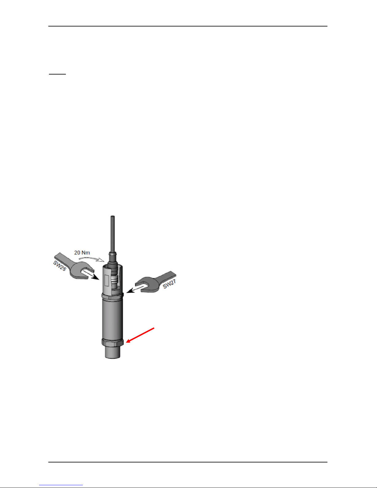
4.2 Installationshinweise für Geräte mit Schlagschutz
Installationshinweise für Geräte mit M12×1 Stecker mit Schlagschutz-/Sicherungs- Metallhülse für
den Einsatz in:
ATEX
II 3G Ex nA IIC T6, T5 Gc
II 1D Ex ta IIIC T80/T90°C T
500
90/100°C Da
II 2D Ex tb III C T80/T90°C Db
Zur Einhaltung der Sicherheitsrichtlinien ist, für diese Schutzklassen und Einsatzbereiche, die
Verwendung der Schlagschutz-/ Sicherungs- Metallhülse zwingend erforderlich.
Die Schlüsselfläche 27mm an der Seite des elektrischen Anschlusses dient nur zum Fixieren des
Druckmessumformers bei Installation der Schlagschutz-/Sicherungs-Metallhülse.
Das Anschlusskabel mit M12x1 Stecker muss im spannungslosen Zustand ordnungsgemäß
angeschlossen werden, damit sich die Steckverbindung bei Vibrationen nicht lösen kann.
Die mitgelieferte Schlagschutz-/Sicherungs-Metallhülse muss ebenfalls ordnungsgemäß mit einem
Anzugsdrehmoment von 20 Nm montiert werden.
Auch die Trennung des M12x1 Steckers darf nur im Spannungslosen Zustand erfolgen.
Nicht zum Fixieren des Sensors
während der Installation der
Metallhülse verwenden!
Page 6

HDA 4000 eigensichere Stromkreise, Schutz durch Gehäuse, ATEX Seite 6 von 26
Stand: 20.03.2018 HYDAC ELECTRONIC GMBH Mat. Nr.: 669723
5 Sicherheitshinweise
Wenn das Etikett nicht mehr lesbar ist, muss der Druckmessumformer außer Betrieb gesetzt
werden.
Die Druckmessumformer sind generell mit einer geeigneten, eigensicheren Barriere zu betreiben.
Die Dichtungen sind in regelmäßigen Abständen, in Abhängigkeit der klimatischen Bedingungen
und dem Medieneinfluss, auf ihre Funktionstüchtigkeit zu kontrollieren, und wenn erforderlich
auszutauschen. Ersatzdichtungen und –flachdichtungen können von der HYDAC ELECTRONIC
GMBH bezogen werden. (Standarddichtungen siehe technische Daten). Diese Überprüfung muss
mindestens alle drei Jahre durchgeführt werden.
Für HDA 41xx / 43xx mit keramischem Sensorelement:
Bei gleichzeitigem Einsatz in Zone 0 und 1 wirkt die Keramik-Messmembrane des
Druckmessumformers als "Trennwand" zwischen Zone 0 und Zone 1. Die Dicke dieser
"Trennwand" ist generell ≤ 1mm und bei Nenndruck unter 1 bar ≤ 0,2 mm. Zur Sicherstellung
dieser Trennfunktion ist unbedingt auf die Verträglichkeit der Messmedien mit den verwendeten
Werkstoffen des Druckmessumformers zu achten, ebenso sind die Überlast- und Berstdrücke
unbedingt einzuhalten (Angaben hierzu siehe "Technische Daten").
Für HDA 44xx / 47xx mit Edelstahl Sensorelement:
Bei gleichzeitigem Einsatz in Zone 0 und 1 wirkt die Metall-Messmembrane des
Druckmessumformers als "Trennwand" zwischen Zone 0 und Zone 1. Die Dicke dieser
"Trennwand" ist generell ≤ 1mm und bei Nenndruck unter 100 bar ≤ 0,2 mm. Zur Sicherstellung
dieser Trennfunktion ist unbedingt auf die Verträglichkeit der Messmedien mit den verwendeten
Werkstoffen des Druckmessumformers zu achten, ebenso sind die Überlast- und Berstdrücke
unbedingt einzuhalten (Angaben hierzu siehe "Technische Daten").
Es ist unbedingt auf die Verträglichkeit der Messmedien zu den Dichtungen und den verwendeten
Werkstoffen des Druckmessumformers zu achten, ebenso sind die Überlast- und Berstdrücke
unbedingt einzuhalten (Angaben hierzu siehe "Technische Daten" und "Sicherheitstechnische
Daten" der EG Baumusterprüfbescheinigung).
Die interne Messmembrane des Druckmessumformers ist unbedingt vor mechanischer
Beschädigung zu schützen. Dieses gilt insbesondere bei Geräten mit einer frontbündigen
Membrane und bei gleichzeitigem Einsatz in Zone 0 und 1 sowie Zone 1 und 2.
Das Trennmittel zwischen der frontbündigen Membrane und der internen Membrane ist Paraffinöl
(Weißöl, S933).
Ebenso ist auf eine ausreichende Dichtung zwischen den Zonen zu achten.
Die Daten hinsichtlich der Nutzung in explosionsgefährdeten Umgebungen sind in jedem Fall zu
berücksichtigen.
Der Betrieb ist nur zulässig, wenn anwendungs- und prozessbedingte intensive elektrostatische
Aufladungsprozesse ausgeschlossen sind.
Bei Einsatz in Atmosphären von brennbaren Stäuben ist der Druckmessumformer
geschützt vor Beschädigungen und Schlag anzubringen.
Aus Sicherheitsgründen sollten Stromversorgung / Ausgangsstromkreis des Druckmessumformers
geerdet werden.
Zur Einhaltung der Sicherheitsrichtlinien ist für die Schutzklassen und Einsatzbereiche:
ATEX:
II 3G Ex nA IIC T6, T5 Gc /II 1D Ex ta IIIC T80/T90°C T
500
90/100°C Da und II 2D Ex tb III C T80/T90°C Db,
die Verwendung der Schlagschutz-/ Sicherungs- Metallhülse zwingend erforderlich.
Die Schlagschutz-/Sicherungs-Metallhülse ist mit einem Anzugsdrehmoment von 20 Nm anzuziehen.
Page 7
HDA 4000 eigensichere Stromkreise, Schutz durch Gehäuse, ATEX Seite 7 von 26
Stand: 20.03.2018 HYDAC ELECTRONIC GMBH Mat. Nr.: 669723
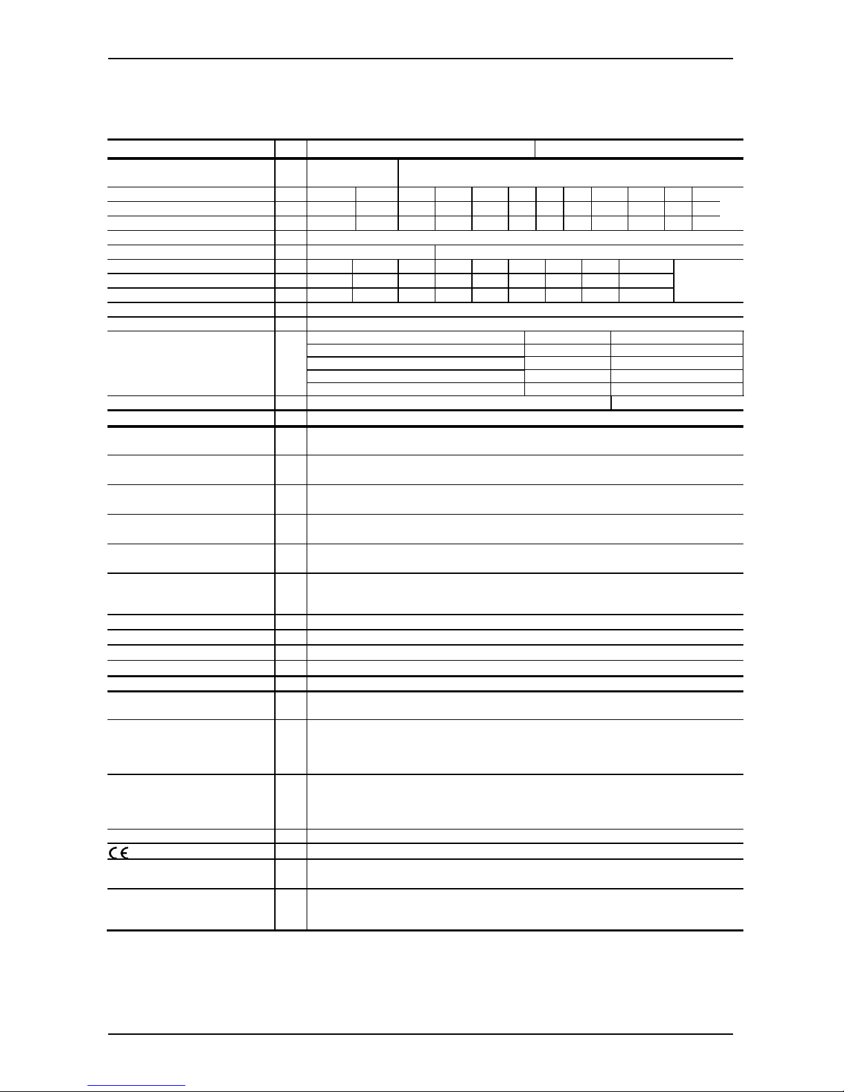
6 Technische Daten
6.1 HDA 4100 / HDA 4300
Eingangskenngrößen
HDA 4100
(Absolutdruck)
HDA 4300
(Relativdruck)
absolut und
relativ
relativ
Messbereiche bar 1 2,5 -1 .. 1 -1.. 9 4 6 10 16 25 40 60 100
Überlastbereiche bar 3 8 3 32 12 20 32 50 80 120 200 200
Berstdruck bar 5 12 5 48 18 30 48 75 120 180 300 300
absolut und relativ relativ
Messbereiche psi 15 30 50 100 150 250 500 1000 1500
Überlastbereiche psi 45 100 150 290 450 725 1500 2900 2900
Berstdruck psi 70 150 250 400 650 1000 2500 4300 4300
Mechanischer Anschluss siehe Typenschlüssel / Abmessungen
Anzugsdrehmoment, empfohlen siehe Abmessungen
Medienberührende Teile
Standard
Frontbündig
Sensor Keramik Keramik
Anschlussstück 1.4301 1.4435; 1.4301
Dichtung FPM /EPDM FPM
O-Ring FPM
Druckmittlerflüssigkeit
Silikon freies Öl
Ausgangsgrößen
Ausgangssignal, zulässige
Bürde
4 .. 20 mA (2-Leiter), R
Lmax.
= (UB – 12 V) / 20 mA [kΩ]
Genauigkeit nach DIN 16086,
Grenzpunkteinstellung
Typ.
Max.
≤ ± 0,5 % FS
≤ ± 1,0 % FS
Genauigkeit bei
Kleinstwerteinstellung (B.F.S.L)
Typ.
Max.
≤ ± 0,25 % FS
≤ ± 0,5 % FS
Temperaturkompensation Typ
≤ ± 0,02 % FS / °C
Nullpunkt Max.
≤ ± 0,03 % FS / °C
Temperaturkompensation Typ.
≤ ± 0,02 % FS / °C
Spanne Max
≤ ± 0,03 % FS / °C
Nicht-Linearität bei
Grenzpunkteinstellung nach
DIN 16086
Max.
≤ ± 0,5 % FS
Hysterese Max.
≤ ± 0,4 % FS
Wiederholbarkeit
≤ ± 0,1 % FS
Anstiegszeit
≤ 1,5 ms
Langzeitdrift Typ.
≤ ± 0,3 % FS / Jahr
Umgebungsbedingungen
Kompensierter
Temperaturbereich
-20 .. +85 °C
Betriebs- /Umgebungstemperaturbereich 1)
T6, T80/85 °C, T
500
90°C : Ta = -20 .. +60°C
T5, T90°C, T
500
100°C: Ta = -20 .. +70°C
T100°C, T
500
110°C: Ta = -20 .. +80°C
T4: Ta = -20 .. +85°C
Mediumstemperaturbereich
1
)
T6, T80/85 °C, T
500
90°C : Ta = -20 .. +60°C
T5, T90°C, T
500
100°C : Ta = -20 .. +70°C
T100°C, T
500
110°C: Ta = -20 .. +80°C
T4: Ta = -20 .. +85°C
Lagertemperaturbereich
-40°C .. +100°C
- Zeichen
EN 61000-6-1/ 2/ 3/ 4 ; EN 60079-0/ 11/ 15/ 26/ 31; EN 50303
Vibrationsbeständigkeit nach
DIN EN 60068-2-6 bei 10 .. 500Hz
≤ 20 g
≤ 10 g bei Geräten mit elektr. Anschluss ½ NPT Conduit
Schutzart nach DIN EN 60529
Schutzart nach ISO 20653
2
)
IP 65 (Stecker Binder 714 M18)
IP 67 (M12x1 Stecker, Stecker EN175301-803)
IP 6K9K (Conduit geschweißt)
Page 8
HDA 4000 eigensichere Stromkreise, Schutz durch Gehäuse, ATEX Seite 8 von 26
Stand: 20.03.2018 HYDAC ELECTRONIC GMBH Mat. Nr.: 669723
Relevante Daten für die
Ex-Anwendung
Ex ia, ic Ex nA, ta, tb, tc
Versorgungsspannung Ui = 12 .. 28 V 12 .. 28 V
Maximaler Speisestrom Ii = 100 mA
Maximale Speiseleistung
Pi = 1W
Max. Leistungsaufnahme ≤ 1W
Anschlusskapazität des
Sensors
Ci = ≤ 22 nF
Induktivität des Sensors Li = 0 mH
Isolationsspannung
3)
50 V AC, mit integriertem Überspannungsschutz nach EN 61000-6-2 oder 500 V AC
Sonstige Größen
Verpolungsschutz der Versorgungsspannung, Überspannungs-,
Übersteuerungsschutz,
Lastkurzschlussfestigkeit
vorhanden
Restwelligkeit
Versorgungsspannung
≤ 5 %
Stromaufnahme
≤ 25 mA
Lebensdauer > 10 Mio. Lastwechsel 0 .. 100% FS
Gewicht ca. 150 g (Standard)
ca. 180 g (frontbündige Ausführung)
ca. 300 g mit ½ Conduit
Anmerkung: FS (Full Scale) = bezogen auf den vollen Messbereich
B.F.S.L.= Best Fit Straight Line
1)
-20°C mit FPM-Dichtung oder EPDM-Dichtung, -40°C auf Anfrage
2)
bei montierter Kupplungsdose entsprechender Schutzart
3)
siehe Typenschlüssel „Isolationsspannung“
6.2 HDA 4400 / HDA 4700
Eingangskenngrößen
HDA 4400
HDA 4700
Messbereiche bar
-1 .. 5 -1..9 2,5 6 16 25 40 60 100 160 250 400 600 100016002000
Überlastbereiche bar
15 20 6 15 32 50 80
120
200 320 500 800 9001)160024003000
Berstdruck bar
100 100 100 100 200 125
200 300
500 800
1000
20002000 300030004000
Messbereich psi
-15..50 -15..75 100 150 200 300 400 500 600
psi
1500 2000 3000 5000 6000 9000 10000 15000 20000 30000
Überlastbereich psi
210 210 290 290 460 1160 1160 1160 1160
psi
2900 4600 7250 11600 11600
13050
1)
13050
1)
23200 34800 43500
Berstdruck psi
1450 1450 1450 1450 2900 2900 2900 2900 2900
psi
7250 11600 14500 29000 29000 29000 29000 43500 43500 58000
Mechanischer Anschluss siehe Typenschlüssel / Abmessungen
Anzugsdrehmoment, empfohlen siehe Abmessungen
Medienberührende Teile
Standard
Frontbündig
Edelstahl 1
.4542; 1.4571; 1.4435; 1.4404; 1.4301; 1.4548
1.4435; 1.4301
Dichtung FPM FPM
O-Ring FPM
Druckmittlerflüssigkeit
Silikon freies Öl
Ausgangsgrößen
Ausgangssignal, zulässige
Bürde
4 .. 20 mA (2-Leiter), R
Lmax.
= (UB – 12 V) / 20 mA [kΩ]
Genauigkeit nach DIN 16086,
Grenzpunkteinstellung
Typ.
Max.
≤ ± 0,5 % FS
≤ ± 1,0 % FS
≤ ± 0,25 % FS
≤ ± 0,5 % FS
Genauigkeit bei
Kleinstwerteinstellung (B.F.S.L)
Typ.
Max.
≤ ± 0,25 % FS
≤ ± 0,5 % FS
≤ ± 0,15 % FS
≤ ± 0,25 % FS
Temperaturkompensation Typ.
≤ ± 0,015 % FS/ °C ≤ ± 0,008 % FS/ °C
Nullpunkt Max.
≤ ± 0,025 % FS/ °C ≤ ± 0,015 % FS/ °C
Temperaturkompensation Typ.
≤ ± 0,015 % FS/ °C ≤ ± 0,008 % FS/ °C
Spanne Max.
≤ ± 0,025 % FS/ °C ≤ ± 0,015 % FS/ °C
Nicht-Linearität bei Grenzpunkteinstellung nach DIN 16086
Max.
≤ ± 0,3% FS
≤ ± 0,3 % FS
Hysterese Max.
≤ ± 0,4 % FS ≤ ± 0,1 % FS
Wiederholbarkeit
≤ ± 0,1 % FS ≤ ± 0,05 % FS
Anstiegszeit
≤ 1,5 ms ≤ 1,5 ms
Langzeitdrift Typ.
≤ ± 0,3 % FS / Jahr ≤ ± 0,1 % FS / Jahr
Page 9
HDA 4000 eigensichere Stromkreise, Schutz durch Gehäuse, ATEX Seite 9 von 26
Stand: 20.03.2018 HYDAC ELECTRONIC GMBH Mat. Nr.: 669723
Umgebungsbedingungen
Kompensierter
Temperaturbereich
-25 .. +85 °C
Betriebs-/ Umgebungstemperaturbereich 2)
T6, T80/85 °C, T
500
90°C : Ta = -20 .. +60°C
T5, T90°C, T
500
100°C: Ta = -20 .. +70°C
T100°C, T
500
110°C: Ta = -20 .. +80°C
T4: Ta = -20 .. +85°C
Mediumstemperaturbereich 2) T6, T80/85 °C, T
500
90°C : Ta = -20 .. +60°C
T5, T90°C, T
500
100°C : Ta = -20 .. +70°C
T100°C, T
500
110°C: Ta = -20 .. +80°C
T4: Ta = -20 .. +85°C
Lagertemperaturbereich -40 .. +100 °C
- Zeichen
EN 61000-6-1/ 2/ 3/ 4 ; EN 60079-0/ 11/ 15/ 26/ 31 ; EN 50303
Vibrationsbeständigkeit nach
DIN EN 60068-2-6 bei 10 ..500Hz
≤ 20 g
≤ 10 g bei Geräten mit elektr. Anschluss ½ NPT Conduit
Schutzart nach DIN EN 60529
Schutzart nach ISO 20653
3)
IP 65 (Stecker Binder 714 M18)
IP 67 (M12x1 Stecker, Stecker EN175301-803)
IP6K9K (Conduit geschweißt)
Relevante Daten für die Ex
-
Anwendung
Ex ia, ic Ex nA, ta, tb, tc
Versorgungsspannung Ui = 12 .. 28 V 12 .. 28 V
Maximaler Speisestrom Ii = 100 mA
Maximale Speiseleistung Pi = 1W
Max. Leistungsaufnahme ≤ 1W
Anschlusskapazität des
Sensors
Ci = ≤ 22 nF
Induktivität des Sensors Li = 0 mH
Isolationsspannung
4
)
50 V AC, mit integriertem Überspannungsschutz nach EN 61000-6-
2 oder 500 VAC
Sonstige Größen
Verpolungsschutz der Versorgungsspannung, Überspannungs-,
Übersteuerungsschutz,
Lastkurzschlussfestigkeit
vorhanden
Restwelligkeit
Versorgungsspannung
≤ 5 %
Stromaufnahme
≤ 25 mA
Lebensdauer
5
)
> 10 Mio. Lastwechsel 0 .. 100% FS
Gewicht ca. 150 g (Standard)
ca. 180 g (Frontbündig)
ca. 300 g mit 1/2 Conduit
Anmerkung: FS (Full Scale) = bezogen auf den vollen Messbereich
B.F.S.L.= Best Fit Straight Line
1)
in der Standardausführung Überlastbereich 1000 bar (14500 psi), in der Ausführung Frontbündig Überlastbereich 900 bar (13050 psi)
2)
-20°C mit FPM-Dichtung oder EPDM-Dichtung, -40°C auf Anfrage
3)
bei montierter Kupplungsdose entsprechender Schutzart
4)
siehe Typenschlüssel „Isolationsspannung“
5)
Messbereich ≥ 1000 bar: >1 Million Lastwechsel (0 .. 100 % FS)
Page 10

HDA 4000 eigensichere Stromkreise, Schutz durch Gehäuse, ATEX Seite 10 von 26
Stand: 20.03.2018 HYDAC ELECTRONIC GMBH Mat. Nr.: 669723
7 Typenschlüssel zur Identifikation des gelieferten Gerätes
7.1 Standard
7.1.1 Typenschlüssel HDA 4100 / HDA 4300
Mechanischer Anschluss
HDA 4 X X X - A - XXXXX - A X X - XXX - F1 (psi) XX inch
Elektrischer Anschluss
Messbereiche
Zulassung
A = ATEX (genauere Angaben siehe Zertifikat)
Modifikationsnummer
(psi
)
Zusätzliche Kennzeichnung für psi-Messbereiche (entfällt bei bar-Messbereichen)
Kabellänge (z.B. für Conduit-
Rohranschluss oder freies Kabelende)
Angabe in m oder inch im Klartext
1 = 1% FS max., Keramik absolut
3 = 1% FS max., Keramik relativ
4 = G 1/4 A ISO 1179-2, Außengewinde
5 = 7/16-20 UNF 2B (SAE 4), Innengewinde
6 = 7/16-20 UNF 2A (SAE 4), Außengewinde
7 = 9/16-18 UNF 2A (SAE 6), Außengewinde
8 = 1/4-18 NPT, Außengewinde
C = SF250CX20, Autoclave (7/16-20 UNF 2B), Innengewinde
F = 1/4-18 NPT, Innengewinde
1 = freies Kabelende
4 = Gerätestecker, Binder Serie 714 M18, 4 pol.
5 = Gerätestecker, EN 175301-803, 3 pol. + PE
6 = Gerätestecker, M 12 x 1, 4 pol.
9 = 1/2-14 NPT Conduit (Außengewinde) Einzeladern
A = Gerätestecker EN 175301-803, 3 pol. + PE, 1/2" Conduit Innengewinde
G = 1/2-14 NPT Conduit (Außengewinde) freies Kabelende
Signal
Angabe in bar oder psi (bei psi zusätzliches Kennzeichen nach der
Modifikationsnummer)
000 = Standard
(andere Nummer wird z.B. verwendet für: Versionen Düse, PIN-Belegung, Stecker am freien Kabelende)
Dichtungsmaterial (medienberührend)
Anschlussmaterial (medienberührend)
1 = Edelstahl
F = FPM-Dichtung (z.B. für Hydrauliköle)
E = EPDM
-
Dichtung (z.B. für Kältemittel)
A = 4 .. 20 mA
Isolationsspannung
H = 500 V AC gegen Gehäuse
N = 50 V AC gegen Gehäuse
Schutzklassen und Einsatzgebiete (siehe Tabelle, Kap.7.3)
ATEX
1 =
I M1 Ex ia I Ma
II 1G Ex ia IIC T6 Ga
II 1/2G Ex ia IIC T6 Ga/Gb
II 2G Ex ia IIC T6 Gb
II 1D Ex ia IIIC T85°C Da
9 = II 3G Ex nA IIC T6, T5 Gc 1)
A =
II 1D Ex ta IIIC T80/T90°C T
500
90/100°C Da
II 2D Ex tb IIIC T80/T90°C Db 1)
C =
II 3G Ex ic IIC T6,T5 Gc
II 3D Ex ic IIIC T80/T90°C Dc
Genauigkei
t
1)
Bei elektrischem Anschluss “6“ nur in Verbindung mit der Schlagschutz-Sicherungs-Metallhülse
Page 11

HDA 4000 eigensichere Stromkreise, Schutz durch Gehäuse, ATEX Seite 11 von 26
Stand: 20.03.2018 HYDAC ELECTRONIC GMBH Mat. Nr.: 669723
7.1.2 Typenschlüssel HDA 4400 / HDA 4700
Genauigkeit
Mechanischer Anschluss
HDA 4 X X X - A - XXXXX - A X X -
XXX (psi) XX inch
Elektrischer Anschluss
Messbereiche
Zulassung
A = ATEX (genauere Angaben siehe Zertifikat)
Modifikationsnummer
(psi)
Zusätzliche Kennzeichnung für psi-Messbereiche (entfällt bei bar-
Messbereichen)
Kabellänge (z.B. für Conduit-Rohranschluss oder freies Kabelende)
Angabe in m oder
inch im Klartext
4 = 1% FS max.
7 = 0,5% FS max.
Mechanischer Anschluss
1 = G1/2 DIN EN 837
2 = G1/2 A ISO 1179-2
4 = G 1/4 A ISO 1179-2, Außengewinde
5 = 7/16-20 UNF 2B (SAE 4), Innengewinde
6 = 7/16-20 UNF 2A (SAE 4), Außengewinde
7 = 9/16-18 UNF 2A (SAE 6), Außengewinde
8 = 1/4-18 NPT, Außengewinde
B = F250C Autoclave (9/16-18 UNF2B), Innengewinde
C = SF250CX20, Autoclave (7/16-20 UNF 2B), Innengewinde
F = 1/4-18 NPT, Innengewinde
1 = freies Kabelende
4 = Gerätestecker, Binder Serie 714 M18, 4 pol.
5 = Gerätestecker, EN 175301-803, 3 pol. + PE
6 = Gerätestecker, M 12 x 1, 4 pol.
9 = 1/2-14 NPT Conduit (Außengewinde) Einzeladern
A = Gerätestecker EN 175301-803, 3 pol. + PE, 1/2" Conduit Innengewinde
G = 1/2-14 NPT Conduit (Außengewinde) freies Kabelende
Signal
Angabe in bar oder psi (bei psi zusätzliches Kennzeichen nach der
Modifikationsnummer)
000 = Standard
(andere Nummer wird z.B. verwendet für: Versionen Düse, PIN-Belegung, Stecker am freien Kabelende)
A = 4 .. 20 mA
Isolationsspannung
H = 500 V AC gegen Gehäuse
N = 50 V AC gegen Gehäuse
Schutzklassen und Einsatzgebiete (siehe Tabelle, Kap.7.3)
ATEX
1 =
I M1 Ex ia I Ma
II 1G Ex ia IIC T6 Ga
II 1/2GEx ia IIC T6 Ga/Gb
II 2G Ex ia IIC T6 Gb
II 1D Ex ia IIIC T85°C Da
9 = II 3G Ex nA IIC T6,T5 Gc 1)
A =
II 1D Ex ta IIIC T80/T90°C T
500
90/100°C Da
II 2D Ex tb IIIC T80/T90°C Db 1)
C =
II 3G Ex ic IIC T6,T5 Gc
II 3D Ex ic IIIC T80/T90°C Dc
1)
Bei elektrischem Anschluss “6“ nur in Verbindung mit der Schlagschutz-Sicherungs-Metallhülse
Page 12

HDA 4000 eigensichere Stromkreise, Schutz durch Gehäuse, ATEX Seite 12 von 26
Stand: 20.03.2018 HYDAC ELECTRONIC GMBH Mat. Nr.: 669723
7.2 Typenschlüssel mit frontbündiger Membran
7.2.1 Typenschlüssel HDA 4300 mit frontbündiger Membran
Genauigkeit
3 = 1% FS max., Keramik relativ
Prozessanschluss
Z = Frontbündig
Anschlussart Elektrisch
1 = freies Kabelende
4 = Gerätestecker, Binder Serie 714 M18, 4 pol.
5 = Gerätestecker, EN 175301-803, 3 pol. + PE
6 = Gerätestecker, M 12 x 1, 4 pol.
9 = 1/2-14 NPT Conduit (Außengewinde) Einzeladern
A = Gerätestecker EN 175301-803, 3 pol. + PE, 1/2" Conduit
Innengewinde
G = 1/2-14 NPT Conduit (Außengewinde) freies Kabelende
Signal
A = 4 .. 20 mA
Messbereiche
Angabe in bar oder psi (bei psi zusätzliches Kennzeichen
nach der Modifikationsnummer)
Anschlussart mechanisch
G01 = G1/2 A, DIN 3852
G02 = G1/2 mit zusätzlicher frontseitiger O-Ring Dichtung
G04 = G1/4 mit zusätzlicher frontseitiger O-Ring-Dichtung
Zulassung
A = ATEX (genauere Angaben siehe Zertifikat)
Isolationsspannung
H = 500 V AC
gegen Gehäuse
N = 50 V AC
gegen Gehäuse
Schutzklassen und Einsatzgebiete (siehe Tabelle, Kap.7.3)
ATEX
1 =
I M1 Ex ia I Ma
II 1G Ex ia IIC T6 Ga
II 1/2G Ex ia IIC T6 Ga/Gb
II 2G Ex ia IIC T6 Gb
II 1D Ex ia IIIC T85°C Da
9 = II 3G Ex nA IIC T6, T5 Gc 1)
A =
II 1D Ex ta IIIC T80/T90°C T
500
90/100°C Da
II 2D Ex tb IIIC T80/T90°C Db 1)
C =
II 3G Ex ic IIC T6, T5 Gc
II 3D Ex ic IIIC T80/T90°C Dc
Modifikationsnummer
000 = Standard
(andere Nummer wird z.B. verwendet für: Versionen Düse, PIN-Belegung, Stecker am freien Kabelende)
(psi)
Zusätzliche Kennzeichnung für psi-Messbereiche (entfällt bei bar-Messbereichen)
Kabellänge (z.B. für Conduit-Rohranschluss oder freies Kabelende)
Angabe in m oder inch im Klartext
HDA 4 3 Z X - A - XXXX - XXX - ANX – XXX (psi) XX inch
1)
Bei elektrischem Anschluss “6“ nur in Verbindung mit der Schlagschutz-Sicherungs-Metallhülse
Page 13

HDA 4000 eigensichere Stromkreise, Schutz durch Gehäuse, ATEX Seite 13 von 26
Stand: 20.03.2018 HYDAC ELECTRONIC GMBH Mat. Nr.: 669723
7.2.2 Typenschlüssel HDA 4400 / HDA 4700 mit frontbündiger Membran
Genauigkeit
4 =
1% FS max
7 =
0,5 % FS max
Prozessanschluss
Z = Frontbündig
Anschlussart Elektrisch
1 = freies Kabelende
4 = Gerätestecker, Binder Serie 714 M18, 4 pol.
5 = Gerätestecker, EN 175301-803, 3 pol. + PE
6 = Gerätestecker, M 12 x 1, 4 pol.
9 = 1/2-14 NPT Conduit (Außengewinde) Einzeladern
A = Gerätestecker EN 175301-803, 3 pol. + PE, 1/2" Conduit
Innengewinde
G = 1/2-14 NPT Conduit (Außengewinde) freies Kabelende
Signal
A = 4 .. 20 mA
Messbereiche
Angabe in bar oder psi (bei psi zusätzliches Kennzeichen
nach der Modifikationsnummer)
Anschlussart mechanisch
G01 = G1/2 A, DIN 3852
G02 = G1/2 mit zusätzlicher frontseitiger O-Ring Dichtung
G04 = G1/4 mit zusätzlicher frontseitiger O-Ring-Dichtung
Zulassung
A = ATEX (genauere Angaben siehe Zertifikat)
Isolationsspannung
H = 500 V AC
gegen Gehäuse
N = 50 V AC
gegen Gehäuse
Schutzklassen und Einsatzgebiete (siehe Tabelle, Kap.7.3)
ATEX
1 =
I M1 Ex ia I Ma
II 1G Ex ia IIC T6 Ga
II 1/2G Ex ia IIC T6 Ga/Gb
II 2G Ex ia IIC T6 Gb
II 1D Ex ia IIIC T85°C Da
9 =
II 3G Ex nA IIC T6, T5 Gc 1)
A =
II 1D Ex ta IIIC T80/T90°C T
500
90/100°C Da
II 2D Ex tb IIIC T80/T90°C Db 1)
C =
II 3G Ex ic IIC T6, T5 Gc
II 3D Ex ic IIIC T80/T90°C Dc
Modifikationsnummer
000 = Standard
(andere Nummer wird z.B. verwendet für: Versionen Düse, PIN-Belegung, Stecker am freien Kabelende)
(psi)
Zusätzliche Kennzeichnung für psi-Messbereiche (entfällt bei bar-Messbereichen)
Kabellänge (z.B. für Conduit-Rohranschluss oder freies Kabelende)
Angabe in m oder inch im Klartext
HDA 4 X Z X - A - XXXXX - XXX - ANX - XXX (psi) XX inch
1)
Bei elektrischem Anschluss “6“ nur in Verbindung mit der Schlagschutz-Sicherungs-Metallhülse
Page 14
HDA 4000 eigensichere Stromkreise, Schutz durch Gehäuse, ATEX Seite 14 von 26
Stand: 20.03.2018 HYDAC ELECTRONIC GMBH Mat. Nr.: 669723
7.3 Auswertetabelle (Protection concept): Zuordnung der Schutzklassen und Einsatzbereiche
Protection concept (Schutzklassen und Einsatzbereiche)
Kennzahl
-
Typenschlüssel
1 9 A C
ATEX
KEMA 05 ATEX 1016X
I M1 Ex ia I Ma
II 1G Ex ia IIC T6 Ga
II 1/2G Ex ia IIC T6 Ga/Gb
II 1D Ex ia lIIC T85°C Da
II 2G Ex ia IIC T6 Gb
II 3G Ex nA llC T6,T5 Gc
II 1D Ex ta lllC T80/T90°C
T
500
90/100°C Da
II 2D Ex tb lllC T80/T90°C Db
II 3G Ex ic llC T6,T5 Gc
ll 3D Ex ic lllC T80/T90°C Dc
Einsatzgebiete
Bergbau
Schutzart:
eigensicher ia mit
Barriere
Gase/
leitender Staub
Schutzart:
eigensicher ia
mit Barriere
Gase
Schutzart:
eigensicher ia
mit Barriere
Gase
Schutzart:
nicht funkend nA
leitender Staub
Schutzart:
staubgeschütztes Gehäuse
Gase/
leitender Staub
Schutzart:
Eigensicher ic
mit Barriere
Elektrischer
Anschluss
(siehe
Typenschlüssel)
1, 4, 5, 6, 9, G
1, 6, 9, G 1, 6, 9, G 1, 4, 5, 6, 9, G
8 Seriennummer
In der Seriennummer ist neben der fortlaufenden Seriennummer die Kalenderwoche und das Jahr
der Herstellung des Geräts enthalten.
Aufbau Seriennummer
:
X Fertigungsjahr z.B. : 7 2017
yy Kalenderwoche z.B. : 12 KW 12
k Seriennummer-Index z.B. : -, A, B
zzzzzz fortlaufende Seriennummer z.B. : 123456
9 Anschlussbelegung
Die Anschlussbelegung für den elektrischen Anschluss ist auf dem Typenschild des
Druckmessumformers dargestellt.
xyykzzzzzz
712A123456
Page 15
HDA 4000 eigensichere Stromkreise, Schutz durch Gehäuse, ATEX Seite 15 von 26
Stand: 20.03.2018 HYDAC ELECTRONIC GMBH Mat. Nr.: 669723
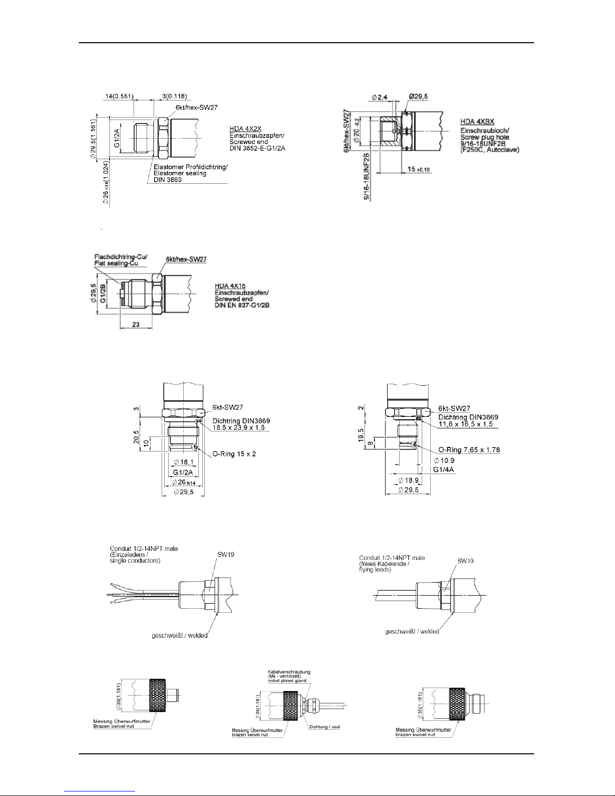
10 Geräteabmessungen
10.1 Mechanische Anschlussvarianten :
7/16-20 UNF 2B (SAE 4), 7/16-20 UNF 2A (SAE 4),
Innengewinde Außengewinde
Anzugsdrehmoment: 15 Nm Anzugsdrehmoment: 15 Nm
9/16-18 UNF 2A (SAE 6), SF 250CX20, Autoclave
Außengewinde (7/16-20 UNF 2B), Innengewinde
Anzugsdrehmoment: 20 Nm Anzugsdrehmoment: 15 Nm
1/4-18 NPT, 1/4-18 NPT,
Außengewinde Innengewinde
Anzugsdrehmoment: maximal 40 Nm Anzugsdrehmoment: maximal 40 Nm
G 1/4 A ISO 1179-2,
Außengewinde
Anzugsdrehmoment: 20 Nm
Gerätestecker
EN 175301
3 pol. + PE
Max 61 (2.405)
Page 16
HDA 4000 eigensichere Stromkreise, Schutz durch Gehäuse, ATEX Seite 16 von 26
Stand: 20.03.2018 HYDAC ELECTRONIC GMBH Mat. Nr.: 669723
G 1/2 A ISO 1179-2 F250C Autoclave (9/16-18 UNF2B), Innengewinde
Anzugsdrehmoment: maximal 45 Nm Anzugsdrehmoment: maximal 40 Nm
G1/2 DIN EN 837
Anzugsdrehmoment: maximal 45Nm
G 1/2 mit zusätzlicher frontseitiger O-Ring-Dichtung, G 1/4 mit zusätzlicher frontseitiger O-Ring-Dichtung
Anzugsdrehmoment: maximal 45 Nm Anzugsdrehmoment: maximal 20 Nm
10.2 Elektrische Anschlussvarianten :
Gerätestecker, M12x1, 4 pol. Freies Kabelende Gerätestecker, Binder Serie 714 M18, 4 pol.
Page 17

HDA 4000 eigensichere Stromkreise, Schutz durch Gehäuse, ATEX Seite 17 von 26
Stand: 20.03.2018 HYDAC ELECTRONIC GMBH Mat. Nr.: 669723
Gerätestecker EN 175301-803 (DIN 43650) , 3 pol. + PE,
1/2" Conduit Innengewinde
Geräteabmessungen
Mit Schlagschutz-Sicherungs-Metallhülse Mit elektrischen Anschluss ½-14 NPT Conduit
Page 18

HDA 4000 eigensichere Stromkreise, Schutz durch Gehäuse, ATEX Seite 18 von 26
Stand: 20.03.2018 HYDAC ELECTRONIC GMBH Mat. Nr.: 669723
11 Zertifikate
11.1 ATEX
Page 19

HDA 4000 eigensichere Stromkreise, Schutz durch Gehäuse, ATEX Seite 19 von 26
Stand: 20.03.2018 HYDAC ELECTRONIC GMBH Mat. Nr.: 669723
Page 20

HDA 4000 eigensichere Stromkreise, Schutz durch Gehäuse, ATEX Seite 20 von 26
Stand: 20.03.2018 HYDAC ELECTRONIC GMBH Mat. Nr.: 669723
Page 21

HDA 4000 eigensichere Stromkreise, Schutz durch Gehäuse, ATEX Seite 21 von 26
Stand: 20.03.2018 HYDAC ELECTRONIC GMBH Mat. Nr.: 669723
Page 22

HDA 4000 eigensichere Stromkreise, Schutz durch Gehäuse, ATEX Seite 22 von 26
Stand: 20.03.2018 HYDAC ELECTRONIC GMBH Mat. Nr.: 669723
Page 23

HDA 4000 eigensichere Stromkreise, Schutz durch Gehäuse, ATEX Seite 23 von 26
Stand: 20.03.2018 HYDAC ELECTRONIC GMBH Mat. Nr.: 669723
Page 24

HDA 4000 eigensichere Stromkreise, Schutz durch Gehäuse, ATEX Seite 24 von 26
Stand: 20.03.2018 HYDAC ELECTRONIC GMBH Mat. Nr.: 669723
Page 25

HDA 4000 eigensichere Stromkreise, Schutz durch Gehäuse, ATEX Seite 25 von 26
Stand: 20.03.2018 HYDAC ELECTRONIC GMBH Mat. Nr.: 669723
12 Konformitätserklärung
Page 26

HDA 4000 eigensichere Stromkreise, Schutz durch Gehäuse, ATEX Seite 26 von 26
Stand: 20.03.2018 HYDAC ELECTRONIC GMBH Mat. Nr.: 669723
HYDAC ELECTRONIC GMBH
Hauptstraße 27
D-66128 Saarbrücken
Germany
Web: www.hydac.com
E-Mail: electronic@hydac.com
Tel.: +49-(0)6897-509-01
Fax: +49-(0)6897-509-1726
HYDAC Service
Für Fragen zu Reparaturen steht Ihnen der HYDAC Service zur Verfügung:
HYDAC SYSTEMS & SERVICES GMBH
Hauptstr. 27
D-66128 Saarbrücken
Germany
Tel.: +49-(0)6897-509-1936
Fax: +49-(0)6897-509-1933
Anmerkung
Die Angaben in diesem Handbuch beziehen sich auf die beschriebenen
Betriebsbedingungen und Einsatzfälle. Bei abweichenden Einsatzfällen und/oder
Betriebsbedingungen wenden Sie sich bitte an die entsprechende Fachabteilung.
Bei technischen Fragen, Hinweisen oder Störungen nehmen Sie bitte Kontakt mit Ihrer
HYDAC- Vertretung auf.
Technische Änderungen sind vorbehalten.
Page 27

Status: 2018-03-20 HYDAC ELECTRONIC GMBH Mat. No.: 669723
Operating Instructions
Pressure Transmitter Series HDA 4000
Intrinsically safe, dustprotected enclosure,
non-sparking.
ATEX approval
(Translation of the original operating instructions )
Protection Types and Zones:
ATEX
I M1 Ex ia I Ma
II 1G Ex ia IIC T6 Ga
II 1/2 G Ex ia IIC T6 Ga/Gb
II 2 G EX ia IIC T6 Gb
II 1D Ex ia IIIC T85°C Da
II 1D Ex ta IIIC T80/T90/T100°C T
500
90/100/110°C Da
II 2D Ex tb IIIC T80/T90/T100°C Db
II 3G Ex nA IIC T6, T5, T4 Gc
II 3G Ex ic IIC T6, T5, T4 Gc
II 3D Ex tc IIIC T80/T90/T100°C Dc
II 3D Ex ic IIIC T80/T90/T100°C Dc
KEMA 05ATEX1016X
Page 28

HDA 4000 intrinsically safe circuits, protection by enclosure, ATEX Pagte 2 of 26
Status: 2018-03-20 HYDAC ELECTRONIC GMBH Mat. No.: 669723
Table of Contents
1 General............................................................................................................... 3
2 Function ............................................................................................................. 3
3 Installation and Commissioning Information ................................................. 3
4 Important Mounting Instructions ..................................................................... 4
4.1 Installation Instructions for Units with 1/2 “ NPT Conduit ......................... 4
4.2 Installation Instructions for Units with Impact Protection ......................... 5
5 Safety Information ............................................................................................ 6
6 Technical Data ................................................................................................... 7
6.1 HDA 4100 / HDA 4300 ..................................................................................... 7
6.2 HDA 4400 / HDA 4700 ..................................................................................... 8
7 Model Code to identify the delivered part ..................................................... 10
7.1 Standard ........................................................................................................... 10
7.1.1 Model code HDA 4100 / HDA 4300 .............................................................. 10
7.1.2 Model Code HDA 4400 / HDA 4700 .............................................................. 11
7.2 Model Code with Flush Membrane ................................................................ 12
7.2.1 Model Code HDA 4300 with flush membrane ............................................. 12
7.2.2 Model Code HDA 4400 / HDA 4700 with flush membrane ......................... 13
7.3 Evaluation table (Protection concept): Assignment of the protection types
and application areas ......................................................................................... 14
8 Serial Number .................................................................................................. 14
9 Pin assignment ............................................................................................... 14
10 Dimensions ...................................................................................................... 15
10.1 Mechanical Connection Variants ................................................................. 15
10.2 Electrical Connection Variants .................................................................... 16
11 Certificates ...................................................................................................... 18
11.1 ATEX .............................................................................................................. 18
12 Certificate of Conformity ................................................................................ 25
Page 29

HDA 4000 intrinsically safe circuits, protection by enclosure, ATEX Pagte 3 of 26
Status: 2018-03-20 HYDAC ELECTRONIC GMBH Mat. No.: 669723
1 General
If you have any queries regarding technical details or the suitability of the unit for your application,
please contact our Technical Sales Department. The series HDA 4000 pressure transmitters are
individually tested and calibrated at a computer operated test station. They are maintenance-free
and operate perfectly when used according to the data (see Technical Specifications). However, if
there is a cause for complaint, please contact HYDAC Service. Interference by anyone other than
HYDAC personnel will invalidate all warranty claims as well as the ATEX approval.
2 Function
The pressure signal measured by the sensor is converted into a proportional analog
4..20 mA signal. Connection to the power supply is done via a plug connector or a permanently
attached line.
3 Installation and Commissioning Information
The pressure transmitters can be installed directly on the process side via the threaded
connection. It is important to ensure that the membrane is protected from mechanical damage.
This is particularly relevant for instruments with a flush membrane.
In order to prevent mechanical damage when dealing with critical applications involving heavy
vibrations or blows, for example, we recommend securing the unit with an elastomer clamp and
decoupling the hydraulic ports via a Minimess hose.
Tightening torque see dimensions.
Pressure transmitters with a rated pressure of < 100 bar (≤ 1500 psi) provide for pressure
equalization with the ambient pressure. This is enabled by a small hole underneath the plug
connector. The connector is covered on the inside by a special membrane which prevents moisture
from seeping into the unit from the outside. In order to prevent the hole from becoming clogged,
mounting should be done in a horizontal position in moist or dusty environments, or vertically with
the pressure port pointing downwards.
On units with a rated pressure of ≤ 100 bar (≤ 1500 psi) and a ½“ Conduit electrical connection, the
pressure equalization with single conductor is realized by means of a short vent line, using
insulated cables, it is realized by means of a cable with an integrated venting hose. It must be
ensured that the venting only takes place outside the hazardous area.
Connection is to be done by a properly qualified specialist in accordance with the pertinent
regulations pertaining to potentially explosive environments (e.g. EN 60079-14).
The series 4000 pressure transmitters carry the -mark. The certificate of conformity can be
found in the annex.
The requirements of the standards (see technical data) cannot be satisfied unless the pressure
transmitter housing is properly grounded via the mechanical connection or the ½ NPT Conduit. If a
green-yellow wire is available, it can be used additionally for grounding, but may not be used on its
own as the grounding connection. When using hose mounting the housing has to be grounded
separately.
The related intrinsically safe devices (e.g. zener barriers) must also be grounded. A potential
equalisation is required along the intrinsically safe electrical circuit in the N type model (dielectric
strength ≤ 50 VAC).
On the HDA 4000 series, type H (isolation voltage ≤ 500 VAC), the cable length to the pressure
transmitter must be max. 30 m (overvoltage protection to DIN EN 61000-6-2). If the cable length
exceeds 30 m, overvoltage protection must be provided by the customer.
Page 30

HDA 4000 intrinsically safe circuits, protection by enclosure, ATEX Pagte 4 of 26
Status: 2018-03-20 HYDAC ELECTRONIC GMBH Mat. No.: 669723
4 Important Mounting Instructions
4.1 Installation Instructions for Units with 1/2 “ NPT Conduit
Mechanical Installation
The process installation of the transmitters may only be carried out utilizing the flats on the process
connection side.
Electrical Installation
The electrical installation of the transmitter may only be carried out utilizing the flats on the 1/2 NPT
Conduit (cable outlet)
Do not use for screwing into the
mechanical connection!
Do not use for fixing the sensor
during electrical conduit
installation!
Page 31

HDA 4000 intrinsically safe circuits, protection by enclosure, ATEX Pagte 5 of 26
Status: 2018-03-20 HYDAC ELECTRONIC GMBH Mat. No.: 669723
4.2 Installation Instructions for Units with Impact Protection
Installation instructions for units with M12x1 connector with an impact protection metal safety
sleeve for the use in zones:
ATEX
II 3G Ex nA IIC T6, T5 Gc
II 1D Ex ta IIIC T80/T90°C T
500
90/100°C Da
II 2D Ex tb III C T80/T90°C Db
By adherence to safety guidelines in the protection rating and applications: the usage of the impact
protection metal safety sleeve is stringently required.
The electrical installation of the transmitter may only be carried out utilizing the hex.27mm flats on
the installation of the impact protection metal safety sleeve.
The connection of the cable with M12x1 plug may only be carried out properly in order to prevent
the connection from loosing due to vibrations and it must be carried out in voltage-free condition.
The impact protection metal safety sleeve must be properly tightened with a torque of 20 Nm.
Also the separation of the M12x1 connector may only be carried out if the system is in dead state.
Do not use for fixing the sensor
during metal sleeve installation!
Page 32

HDA 4000 intrinsically safe circuits, protection by enclosure, ATEX Pagte 6 of 26
Status: 2018-03-20 HYDAC ELECTRONIC GMBH Mat. No.: 669723
5 Safety Information
The pressure transmitter may no longer be used when the label becomes illegible.
The pressure transmitters are to be used in general with a suitable intrinsically safe barrier.
The seals and gaskets are to be checked to see that they function properly prior to mounting and
at regular intervals in keeping with the climatic conditions and the influence of the media, and to be
changed as needed. Replacement seals and gaskets can be obtained from HYDAC ELECTRONIC
GMBH. (Standard seal see technical data) This check is to be conducted at least every three
years.
HDA 41xx / 43xx with ceramic measurement cell:
If used simultaneously in zones 0 and 1, the ceramics membrane of the pressure transmitter
serves as a partition wall between zones 0 and 1. The thickness of this partition wall is generally
≤ 1mm, and with a nominal pressure ranging below 1 bar, ≤ 0.2 mm. In order to ensure this
partition function, the compatibility of the measuring fluids with the used materials is compulsory,
as well as the overload and bursting pressures must absolutely be complied with (further details,
please see "Technical Data").
HDA 44xx / 47xx with stainless steel membrane:
If used simultaneously in zones 0 and 1, the metal membrane of the pressure transmitter serves as
a partition wall between zones 0 and 1. The thickness of this partition wall is generally ≤ 1mm, and
with a nominal pressure ranging below 100 bar, ≤ 0.2 mm. In order to ensure this partition function,
the compatibility of the measuring fluids with the used materials is compulsory, as well as the
overload and bursting pressures must absolutely be complied with (further details, please see
"Technical Data").
It is imperative that the measurement fluid is compatible with the materials used in the pressure
transmitter; similarly, the overload pressures and bursting pressures must be adhered to without
fail (for these specifications, see the “Technical Specifications” and “Safety Information” of the EC
type examination certificate).
The internal measurement membrane of the pressure transmitter is to be protected against
mechanical damage. This applies especially for transmitters with flush membrane if the unit is
used simultaneously in zones 0 and 1 equally zones 1 and 2.
The transfer media between the flush membrane and the internal measurement membrane is
paraffin oil (white oil, S933).
Please ensure sufficient sealing between the zones as well.
The data pertaining to use in Hazardous Location is to be heeded in any event.
Operation is only permitted when operational and process related intensive electrostatic changes
are eliminated.
When used in atmospheres containing combustible dusts, the pressure transmitter must be
installed in such a way that it is protected from damage and knocks.
From a safety point of view, the supply / output circuit of pressure transmitter shall be considered
to be connected to earth.
By adherence to safety guidelines in the protection rating and applications:
ATEX:
II 3G Ex nA IIC T6, T5 Gc /II 1D Ex ta IIIC T80/T90°C T
500
90/100°C Da und II 2D Ex tb III C T80/T90°C Db,
The impact protection metal safety sleeve must be tightened with a torque of 20 Nm.
Page 33

HDA 4000 intrinsically safe circuits, protection by enclosure, ATEX Pagte 7 of 26
Status: 2018-03-20 HYDAC ELECTRONIC GMBH Mat. No.: 669723
6 Technical Data
6.1 HDA 4100 / HDA 4300
Input data
HDA 4100
(Absolute pressure)
HDA 4300
(Relative pressure)
absolute and
relative
relative
Measuring Ranges bar 1 2.5 -1 .. 1 -1.. 9 4 6 10 16 25 40 60 100
Overload ranges bar 3 8 3 32 12 20 32 50 80 120 200 200
Burst pressure bar 5 12 5 48 18 30 48 75 120 180 300 300
absolute and relative relative
Measuring Ranges psi 15 30 50 100 150 250 500 1000 1500
Overload ranges psi 45 100 150 290 450 725 1500 2900 2900
Burst pressure psi 70 150 250 400 650 1000 2500 4300 4300
Mechanical connection see model code / dimensions
Tightening torque, recommended See dimensions
Parts in contact with fluid
Standard
Flush membrane
Sensor Ceramic Ceramic
Flange connection 1.4301 1.4435; 1.4301
seals FPM /EPDM FPM
O-ring FPM
Pressure transfer fluid
Silicon-free oil
Output data
Output signal, permitted
resistance
4 .. 20 mA (2-conductor), R
Lmax.
= (UB – 12 V) / 20 mA [kΩ]
Accuracy to DIN 16086,
terminal based
Typ.
Max.
≤ ± 0.5 % FS
≤ ± 1.0 % FS
Accuracy, B.F.S.L. Typ.
Max.
≤ ± 0.25 % FS
≤ ± 0.5 % FS
Temperature compensation Type
≤ ± 0.02 % FS / °C
Zero point Max.
≤ ± 0.03 % FS / °C
Temperature compensation Typ.
≤ ± 0.02 % FS / °C
Span Max.
≤ ± 0.03 % FS / °C
Non-linearity at max. setting to
DIN 16086
Max.
≤ ± 0.5 % FS
Hysteresis Max.
≤ ± 0.4 % FS
Repeatability
≤ ± 0.1 % FS
Rise time
≤ 1.5 ms
Long term drift Typ.
≤ ± 0.3 % FS / year
Ambient
conditions
Compensated temperature
range
-20 .. +85°C
Operation / ambient
temperature range 1)
T6, T80/85 °C, T
500
90°C : Ta = -20 .. +60°C
T5, T90°C, T
500
100°C: Ta = -20 .. +70°C
T100°C, T
500
110°C: Ta = -20 .. +80°C
T4: Ta = -20 .. +85°C
Fluid temperature range
1
)
T6, T80/85 °C, T
500
90°C : Ta = -20 .. +60°C
T5, T90°C, T
500
100°C : Ta = -20 .. +70°C
T100°C, T
500
110°C: Ta = -20 .. +80°C
T4: Ta = -20 .. +85°C
Storage temperature range -40°C .. +100°C
- mark
EN 61000-6-1/ 2/ 3/ 4 ; EN 60079-0/ 11/ 15/ 26/ 31; EN 50303
Vibration resistance to
DIN EN 60068-2-6 at 10.. 500 Hz
≤ 20 g
≤ 10 g in devices with electrical connection 1/2 NPT Conduit
Protection class to
DIN EN 60529
Protection class to ISO 20653
2)
IP 65 (connector Binder 714 M18)
IP 67 (M12x1 male connector, connector EN175301-803)
IP 6K9K (Conduit welded)
Page 34

HDA 4000 intrinsically safe circuits, protection by enclosure, ATEX Pagte 8 of 26
Status: 2018-03-20 HYDAC ELECTRONIC GMBH Mat. No.: 669723
Relevant data for Ex
applications
Ex ia, ic Ex nA, ta, tb, tc
Supply voltage Ui = 12 .. 28 V 12 .. 28 V
Max. input current Ii = 100 mA
Maximum input power
Pi = 1W
Max. power consuption ≤ 1W
Connection capacitance of the
sensor
Ci = ≤ 22 nF
Inductance of the sensor Li = 0 mH
Insulation voltage
3)
50 V AC, with integrated overvoltage protection to EN 61000-6-2 or 500 V AC
Other data
Reverse polarity protection of the
supply voltage, overvoltage,
override and short circuit protection
Standard
Residual ripple supply voltage
≤ 5%
Current consumption
≤ 25 mA
Life expectancy > 10 million load cycles 0 .. 100 %FS
Weight approx. 150 g (Standard)
approx. 180 g (flush mount version)
approx. 300 g with ½ Conduit
Note: FS (Full Scale) = relative to the full measuring range
B.F.S.L.= Best Fit Straight Line
1)
-20 °C with FPM or EPDM seal, -40 °C on request
2)
With mounted mating connector in corresponding protection class.
3)
see model code for "insulation voltage"
6.2 HDA 4400 / HDA 4700
Input data
HDA 4400
HDA 4700
Measuring Ranges bar
-1 .. 5 -1..9 2.5 6 16 25 40 60 100 160 250 400 600 1000 1600 2000
Overload ranges bar
15 20 6 15 32 50 80
120
200 320 500 800 9001)160024003000
Burst pressure bar
100 100 100 100 200 125
200 300
500 800
1000
20002000 300030004000
Measuring range psi
-15..50 -15..75 100 150 200 300 400 500 600
psi
1500 2000 3000 5000 6000 9000 10000 15000 20000 30000
Overload pressure psi
210 210 290 290 460 1160 1160 1160 1160
psi
2900 4600 7250 11600 11600
13050
1)
13050
1)
23200 34800 43500
Burst pressure psi
1450 1450 1450 1450 2900 2900 2900 2900 2900
psi
7250 11600 14500 29000 29000 29000 29000 43500 43500 58000
Mechanical connection see model code / dimensions
Tightening torque, recommended See dimensions
Parts in contact with fluid
Standard
Flush membrane
Stainless
steel
1
.4542; 1.4571; 1.4435; 1.4404; 1.4301; 1.4548
1.4435; 1.4301
seals FPM FPM
O-ring FPM
Pressure transfer fluid
Silicon-free oil
Output data
Output signal, permitted
resistance
4 .. 20 mA (2-conductor), R
Lmax.
= (UB – 12 V) / 20 mA [kΩ]
Accuracy to DIN 16086,
terminal
based
Typ.
Max.
≤ ± 0.5 % FS
≤ ± 1.0 % FS
≤ ± 0.25 % FS
≤ ± 0.5 % FS
Accuracy, B.F.S.L. Typ.
Max.
≤ ± 0.25 % FS
≤ ± 0.5 % FS
≤ ± 0.15 % FS
≤ ± 0.25 % FS
Temperature compensation Typ.
≤ ± 0.015 % FS / °C ≤ ± 0.008 % FS / °C
zero point Max.
≤ ± 0.025 % FS / °C ≤ ± 0.015 % FS / °C
Temperature compensation Typ.
≤ ± 0.015 % FS / °C ≤ ± 0.008 % FS / °C
Span Max.
≤ ± 0.025 % FS / °C ≤ ± 0.015 % FS / °C
Non-linearity at max. setting to
DIN 16086
Max.
≤ ± 0.3% FS
≤ ± 0.3 % FS
Hysteresis Max.
≤ ± 0.4 % FS ≤ ± 0.1 % FS
Repeatability
≤ ± 0.1 % FS ≤ ± 0.05 % FS
Rise time
≤ 1.5 ms ≤ 1.5 ms
Long-term drift Typ.
≤ ± 0.3 % FS / year ≤ ± 0.1 % FS / year
Page 35

HDA 4000 intrinsically safe circuits, protection by enclosure, ATEX Pagte 9 of 26
Status: 2018-03-20 HYDAC ELECTRONIC GMBH Mat. No.: 669723
Ambient conditions
Compensated temperature
range
-25 .. +85°C
Operation / ambient
temperature range 2)
T6, T80/85 °C, T
500
90°C : Ta = -20 .. +60°C
T5, T90°C, T
500
100°C: Ta = -20 .. +70°C
T100°C, T
500
110°C: Ta = -20 .. +80°C
T4: Ta = -20 .. +85°C
Fluid temperature range 2) T6, T80/85 °C, T
500
90°C : Ta = -20 .. +60°C
T5, T90°C, T
500
100°C : Ta = -20 .. +70°C
T100°C, T
500
110°C: Ta = -20 .. +80°C
T4: Ta = -20 .. +85°C
Storage temperature range -40 .. +100°C
- mark
EN 61000-6-1/ 2/ 3/ 4 ; EN 60079-0/ 11/ 15/ 26/ 31 ; EN 50303
Vibration resistance acc. to
DIN EN 60068-2-6 at
10 ..500Hz
≤ 20 g
≤ 10 g in devices with electrical connection 1/2 NPT Conduit
Protection class to
DIN EN 60529
Protection class to ISO 20653
3
)
IP 65 (connector Binder 714 M18)
IP 67 (M12x1 male connector, connector EN175301-803)
IP 6K9K (conduit welded)
Relevant data for Ex
Application
Ex ia, ic Ex nA, ta, tb, tc
Supply voltage Ui = 12 .. 28 V 12 .. 28 V
Max. input current Ii = 100 mA
Maximum input power Pi=1 W
Max. power consuption ≤ 1W
Connection capacitance of the
sensor
Ci = ≤ 22 nF
Inductance of the sensor Li = 0 mH
Insulation voltage
4
)
50 V AC, with integrated overvoltage protection to EN 61000-6-2 or 500 V AC
Other data
Reverse polarity protection of the
supply voltage, overvoltage,
override and short circuit protection
Standard
Residual ripple supply voltage
≤ 5%
Current consumption
≤ 25 mA
Life expectancy
5
)
> 10 million load cycles 0 .. 100 %FS
Weight approx. 150 g (Standard)
approx. 180 g (flush mount version)
approx. 300 g with 1/2 conduit
Note: FS (Full Scale) = relative to the full measuring range
B.F.S.L.= Best Fit Straight Line
1)
Standard: overload rage 1000bar (14500 psi), Flush mount version overload range 900 bar (13050 psi)
2)
-20 °C with FPM or EPDM seal, -40 °C on request
3)
With mounted mating connector in corresponding protection class
4)
see model code for "insulation voltage"
5)
Measuring range ≥ 1000 bar: >1 million load cycles (0 .. 100 % FS)
Page 36

HDA 4000 intrinsically safe circuits, protection by enclosure, ATEX Pagte 10 of 26
Status: 2018-03-20 HYDAC ELECTRONIC GMBH Mat. No.: 669723
7 Model Code to identify the delivered part
7.1 Standard
7.1.1 Model code HDA 4100 / HDA 4300
Mechanical Connection
HDA 4 X X X - A - XXXXX - A X X - XXX - F1 (psi) XX inch
Electrical Connection
Measuring Ranges
Approval
A = ATEX (further details, see certificate
)
Modification number
(psi)
Additional declaration for psi version (escaped for bar version)
Cable length
(e.g. for conduit connection or jacketed cable)
Shown in cm or inch
1 = 1% FS max., ceramic absolute
3 = 1% FS max., ceramic relative
4 = G 1/4 A ISO 1179-2, male
5 = 7/16-20 UNF 2B (SAE 4), female
6 = 7/16-20 UNF 2A (SAE 4), male
7 = 9/16-18 UNF 2A (SAE 6), male
8 = 1/4-18 NPT, male
C = SF250CX, Autoclave (7/16-20 UNF 2B), female
F = 1/4-18 NPT, female
1 = Jacketed cable
4 = Male connector, Binder series 714 M18, 4 pole
5 = Male connector, EN 175301-803, 3 pol. + PE
6 = Male connector M 12 x 1, 4 pol.
9 = 1/2-14 NPT Conduit (male) single leads
A = Male connector EN 175301-803, 3 pole + PE, 1/2" Conduit female
G = 1/2-14 NPT Conduit (male) jacketed cable
Signal
Measuring ranges are shown in bar or psi (in case of psi see
additional psi declaration in model code)
000 = Standard
(other numbers are used for e.g.:version, orifice, pin connection,plug at the end of the jacketed cable)
Seal material (parts in contact with the fluid)
Material of connection (parts in contact with the fluid)
1 = stainless steel
F = FPM-Dichtung (e.g. for hydraulic oils)
E = EPDM
-
seal (e.g. for coolant)
A = 4 .. 20 mA
Insulation voltage
H = 500 V AC to housing
N = 50 V AC to housing
Protection types and applications: (see Tab.,chap.7.3)
ATEX
1 =
I M1 Ex ia I Ma
II 1G Ex ia IIC T6 Ga
II 1/2G Ex ia IIC T6 Ga/Gb
II 2G Ex ia IIC T6 Gb
II 1D Ex ia IIIC T85°C Da
9 = II 3G Ex nA IIC T6, T5 Gc 1)
A =
II 1D Ex ta IIIC T80/T90°C T
500
90/100°C Da
II 2D Ex tb IIIC T80/T90°C Db 1)
C =
II 3G Ex ic IIC T6, T5 Gc
II 3D Ex ic IIIC T80/T90°C Dc
Accuracy
1)
With electrical connection “6“ only in conjunction with the impact protection metal safety sleeve
Page 37

HDA 4000 intrinsically safe circuits, protection by enclosure, ATEX Pagte 11 of 26
Status: 2018-03-20 HYDAC ELECTRONIC GMBH Mat. No.: 669723
7.1.2 Model Code HDA 4400 / HDA 4700
Accuracy
Mechanical connection
HDA 4 X X X - A - XXXXX - A X X -
XXX (psi) XX inch
Electrical Connection
Measuring ranges
Approval
A = ATEX (further details, see certificate)
Modification Number
(psi)
Additional declaration for psi version (escaped for bar version)
Cable length
(e.g. for Conduit connection or jacketed cable)
Shown in cm or inch
4 = 1% FS max.
7 = 0.5% FS max.
Mechanical Connection
1 = G1/2 DIN EN 837
2 = G1/2 A ISO 1179-2
4 = G 1/4 A ISO 1179-2, male
5 = 7/16-20 UNF 2B (SAE 4), female
6 = 7/16-20 UNF 2A (SAE 4), male
7 = 9/16-18 UNF 2A (SAE 6), male
8 = 1/4-18 NPT, male
B = F250C Autoclave (9/16-18 UNF 2B), female
C = SF250CX, Autoclave (7/16-20 UNF 2B), female
F = 1/4-18 NPT, female
1 = jacketed cable
4 = Male connector, Binder series 714 M18, 4 pole
5 = Male connector, EN 175301-803, 3 pol. + PE
9 = 1/2-14 NPT Conduit (male) single leads
A = Male connector EN 175301-803, 3 pole + PE, 1/2" Conduit female
G = 1/2-14 NPT Conduit (male) jacketed cable
Signal
Measuring ranges are shown in bar or psi (in case of psi see
additional psi declaration in model code)
000 = Standard
(other numbers are used for e.g.:version, orifice, pin connection,plug at the end of the free cable)
A = 4 .. 20 mA
Insulation voltage
H = 500 V AC to housing
N = 50 V AC to housing
Protection types and applications: (see Tab.,chap.7.3)
ATEX
1 =
I M1 Ex ia I Ma
II 1G Ex ia IIC T6 Ga
II 1/2G Ex ia IIC T6 Ga/Gb
II 2G Ex ia IIC T6 Gb
II 1D Ex ia IIIC T85°C Da
9 = II 3G Ex nA IIC T6,T5 Gc 1)
A =
II 1D Ex ta IIIC T80/T90°C T
500
90/100°C Da
II 2D Ex tb IIIC T80/T90°C Db 1)
C =
II 3G Ex ic IIC T6,T5 Gc
II 3D Ex ic IIIC T80/T90°C Dc
1)
With electrical connection “6“ only in conjunction with the impact protection metal safety sleeve
Page 38

HDA 4000 intrinsically safe circuits, protection by enclosure, ATEX Pagte 12 of 26
Status: 2018-03-20 HYDAC ELECTRONIC GMBH Mat. No.: 669723
7.2 Model Code with Flush Membrane
7.2.1 Model Code HDA 4300 with flush membrane
Accuracy
3 = 1% FS max., ceramic relative
Mechanical Process Connection
Z = flush membrane
Electrical connection
1 = jacketed cable
4 = Male connector, Binder series 714 M18, 4 pole
5 = Male connector, EN 175301-803, 3 pol. + PE
6 = Male connector M 12 x 1, 4 pol.
9 = 1/2-14 NPT Conduit (male) single leads
A = Male connector EN 175301-803, 3 pole + PE, 1/2" Conduit female
G = 1/2-14 NPT Conduit (male) jacketed cable
Signal
A = 4 .. 20 mA
Measuring ranges
are shown in bar or psi (in case of psi, see additional psi declaration
in model code)
Mechanical Connection
G01 = G1/2 A, DIN 3852
G02 = G1/2 with additional front O-ring seal
G04 = G1/4 with additional front O-ring seal
Approval
A = ATEX (further details, see certificate)
Insulation voltage
H = 500 V AC
to housing
N = 50 V AC
to housing
Protection types and applications: (see Tab.,chap.7.3)
ATEX
1 =
I M1 Ex ia I Ma
II 1G Ex ia IIC T6 Ga
II 1/2G Ex ia IIC T6 Ga/Gb
II 2G Ex ia IIC T6 Gb
II 1D Ex ia IIIC T85°C Da
9 = II 3G Ex nA IIC T6,T5 Gc 1)
A =
II 1D Ex ta IIIC T80/T90°C T
500
90/100°C Da
II 2D Ex tb IIIC T80/T90°C Db 1)
C =
II 3G Ex ic IIC T6,T5 Gc
II 3D Ex ic IIIC T80/T90°C Dc
Modification number
000 = Standard
(other numbers are used for e.g.: version, orifice, pin connection, plug at the end of the free cable)
(psi)
Additional declaration for psi version (escaped for bar version)
Cable length (e.g. for Conduit connection or jacketed cable)
Shown in cm or inch
HDA 4 3 Z X - A - XXXX - XXX - ANX – XXX (psi) XX inch
1)
With electrical connection “6“ only in conjunction with the impact protection metal safety sleeve
Page 39

HDA 4000 intrinsically safe circuits, protection by enclosure, ATEX Pagte 13 of 26
Status: 2018-03-20 HYDAC ELECTRONIC GMBH Mat. No.: 669723
7.2.2 Model Code HDA 4400 / HDA 4700 with flush membrane
Accuracy
4 =
1% FS max
7 =
0.5 % FS max
Mechanical Process Connection
Z = flush membrane
Electrical Connection
1 = jacketed cable
4 = Male connector, Binder series 714 M18, 4 pole
5 = Male connector, EN 175301-803, 3 pol. + PE
9 = 1/2-14 NPT Conduit (male) single leads
A = Male connector EN 175301-803, 3 pole + PE, 1/2" Conduit female
G = 1/2-14 NPT Conduit (male) jacketed cable
Signal
A = 4 .. 20 mA
Measuring ranges
Shown in bar or psi (in case of psi, see additional psi declaration
in model code)
Mechanical Connection
G01 = G1/2 A, DIN 3852
G02 = G1/2 with additional front O-ring seal
G04 = G1/4 with additional front O-ring seal
Approval
A = ATEX (further details, see certificate)
Insulation voltage
H = 500 V AC
to housing
N = 50 V AC
to housing
Protection types and applications: (see Tab.,chap.7.3)
ATEX
1 =
I M1 Ex ia I Ma
II 1G Ex ia IIC T6 Ga
II 1/2G Ex ia IIC T6 Ga/Gb
II 2G Ex ia IIC T6 Gb
II 1D Ex ia IIIC T85°C Da
9 =
II 3G Ex nA IIC T6, T5 Gc 1)
A =
II 1D Ex ta IIIC T80/T90°C T
500
90/100°C Da
II 2D Ex tb IIIC T80/T90°C Db 1)
C =
II 3G Ex ic IIC T6, T5 Gc
II 3D Ex ic IIIC T80/T90°C Dc
Modification number
000 = Standard
(other numbers are used for e.g.: version, orifice, pin connection, plug at the end of the free cable)
(psi)
Additional declaration for psi version (escaped for bar version)
Cable length (e.g. for Conduit connection or jacketed cable)
Shown in cm or inch
HDA 4 X Z X - A - XXXXX - XXX - ANX - XXX (psi) XX inch
1)
With electrical connection “6“ only in conjunction with the impact protection metal safety sleeve
Page 40

HDA 4000 intrinsically safe circuits, protection by enclosure, ATEX Pagte 14 of 26
Status: 2018-03-20 HYDAC ELECTRONIC GMBH Mat. No.: 669723
7.3 Evaluation table (Protection concept): Assignment of the protection types and application
areas
Protection concept
Code for use in
model code
1 9 A
C
ATEX
KEMA 05 ATEX 1016X
I M1 Ex ia I Ma
II 1G Ex ia IIC T6 Ga
II 1/2G Ex ia IIC T6 Ga/Gb
II 1D Ex ia lIIC T85°C Da
II 2G Ex ia IIC T5,T6 Gb
II 3G Ex nA llC T6,T5 Gc
II 1D Ex ta lllC T80/T90°C
T
500
90/100°C Da
II 2D Ex tb lllC T80/T0°C Db
II 3G Ex ic llC T6,T5 Gc
ll 3D Ex ic lllC T80/T90°C Dc
Application areas
Mining
Protection class:
Intrinsically safe ia
with barrier
Gases/ conductive dust
Protection class:
Intrinsically safe ia
with barrier
Gases
Protection class:
Intrinsically safe ia
with barrier
Gases
Protection class:
Non-sparking nA
Conductive dust
Protection class:
Dustproof enclosure
Gases/ conductive dust
Protection class:
Intrinsically safe ic
with barrier
Electrical
connection
(See model code)
1, 4, 5, 6, 9, G 1, 6, 9, G 1, 6, 9, G 1, 4, 5, 6, 9, G
8 Serial Number
The serial number includes the calendar week and year of manufacture of the unit, adjacent to the
sequential serial number.
Configuration of serial number (SN):
XX Manufacturing date e.g. : 7 2017
yy Calendar week e.g. : 12 KW 12
k Change control status e.g. : -, A, B
zzzzzz Sequential serial number e.g. : 123456
9 Pin assignment
The pin assignment for the electrical connection is mentioned at the label of the pressure
transmitter.
xyykzzzzzz
712A123456
Page 41

HDA 4000 intrinsically safe circuits, protection by enclosure, ATEX Pagte 15 of 26
Status: 2018-03-20 HYDAC ELECTRONIC GMBH Mat. No.: 669723
10 Dimensions
10.1 Mechanical Connection Variants
7/16-20 UNF 2B (SAE 4), 7/16-20 UNF 2A (SAE 4),
female male
Torque value: 15 Nm Torque value: 15 Nm
9/16-18 UNF 2A (SAE 6), SF 250CX20, Autoclave
Male (7/16-20 UNF 2B), female
Torque value: 20 Nm Torque value: 15 Nm
1/4-18 NPT, 1/4-18 NPT,
Male female
Torque value max. 40 Nm Torque value: max. 40 Nm
G 1/4 A ISO 1179-2, male
Torque value: 20 Nm
connector
EN 175301
3 pol. + PE
Max 61 (2.405)
Page 42

HDA 4000 intrinsically safe circuits, protection by enclosure, ATEX Pagte 16 of 26
Status: 2018-03-20 HYDAC ELECTRONIC GMBH Mat. No.: 669723
G 1/2 A ISO 1179-2, male F250C Autoclave (9/16-18 UNF2B), female
Torque value max. 45 Nm Torque value max. 40 Nm
G1/2 DIN EN 837
Anzugsdrehmoment: maximal 45Nm
G 1/2 with additional front O-ring-seal, G 1/4 with additional front O-ring-seal
Torque value: max. 45 Nm Torque value: max. 20 Nm
10.2 Electrical Connection Variants
Device plug M12x1, 4 pole, male Jacketed cable Male connector, Binder series 714 M18 4 pole
Page 43

HDA 4000 intrinsically safe circuits, protection by enclosure, ATEX Pagte 17 of 26
Status: 2018-03-20 HYDAC ELECTRONIC GMBH Mat. No.: 669723
Male connection EN 175301-803 (DIN 43650) , 3 pol. + PE,
1/2" Conduit mating
Dimensions
With impact protection metal safety sleeve With electrical connection ½-14 NPT Conduit
Page 44

HDA 4000 intrinsically safe circuits, protection by enclosure, ATEX Pagte 18 of 26
Status: 2018-03-20 HYDAC ELECTRONIC GMBH Mat. No.: 669723
11 Certificates
11.1 ATEX
Page 45

HDA 4000 intrinsically safe circuits, protection by enclosure, ATEX Pagte 19 of 26
Status: 2018-03-20 HYDAC ELECTRONIC GMBH Mat. No.: 669723
Page 46

HDA 4000 intrinsically safe circuits, protection by enclosure, ATEX Pagte 20 of 26
Status: 2018-03-20 HYDAC ELECTRONIC GMBH Mat. No.: 669723
Page 47

HDA 4000 intrinsically safe circuits, protection by enclosure, ATEX Pagte 21 of 26
Status: 2018-03-20 HYDAC ELECTRONIC GMBH Mat. No.: 669723
Page 48

HDA 4000 intrinsically safe circuits, protection by enclosure, ATEX Pagte 22 of 26
Status: 2018-03-20 HYDAC ELECTRONIC GMBH Mat. No.: 669723
Page 49

HDA 4000 intrinsically safe circuits, protection by enclosure, ATEX Pagte 23 of 26
Status: 2018-03-20 HYDAC ELECTRONIC GMBH Mat. No.: 669723
Page 50

HDA 4000 intrinsically safe circuits, protection by enclosure, ATEX Pagte 24 of 26
Status: 2018-03-20 HYDAC ELECTRONIC GMBH Mat. No.: 669723
Page 51

HDA 4000 intrinsically safe circuits, protection by enclosure, ATEX Pagte 25 of 26
Status: 2018-03-20 HYDAC ELECTRONIC GMBH Mat. No.: 669723
12 Certificate of Conformity
Page 52

HDA 4000 intrinsically safe circuits, protection by enclosure, ATEX Pagte 26 of 26
Status: 2018-03-20 HYDAC ELECTRONIC GMBH Mat. No.: 669723
HYDAC ELECTRONIC GMBH
Hauptstraße 27
D-66128 Saarbrücken
Germany
Web: www.hydac.com
E-Mail: electronic@hydac.com
Tel.: +49-(0)6897-509-01
Fax: +49-(0)6897-509-1726
HYDAC Service
If you have any questions concerning repair work, please do not hesitate to contact
HYDAC Service:
HYDAC SYSTEMS & SERVICES GMBH
Hauptstr. 27
D-66128 Saarbruecken
Germany
Tel.: +49-(0)6897-509-1936
Fax: +49-(0)6897-509-1933
Note
The information and particulars provided in this manual apply to the operating conditions
and applications described herein. For applications and operating conditions not
described, please contact the relevant technical department.
If you have any questions, suggestions, or encounter any problems of a technical nature,
please contact your Hydac representative.
Subject to technical modifications.
 Loading...