

Page 1
97
E 3.501.26/03.12
1. DESCRIPTION
1.1. FUNCTION
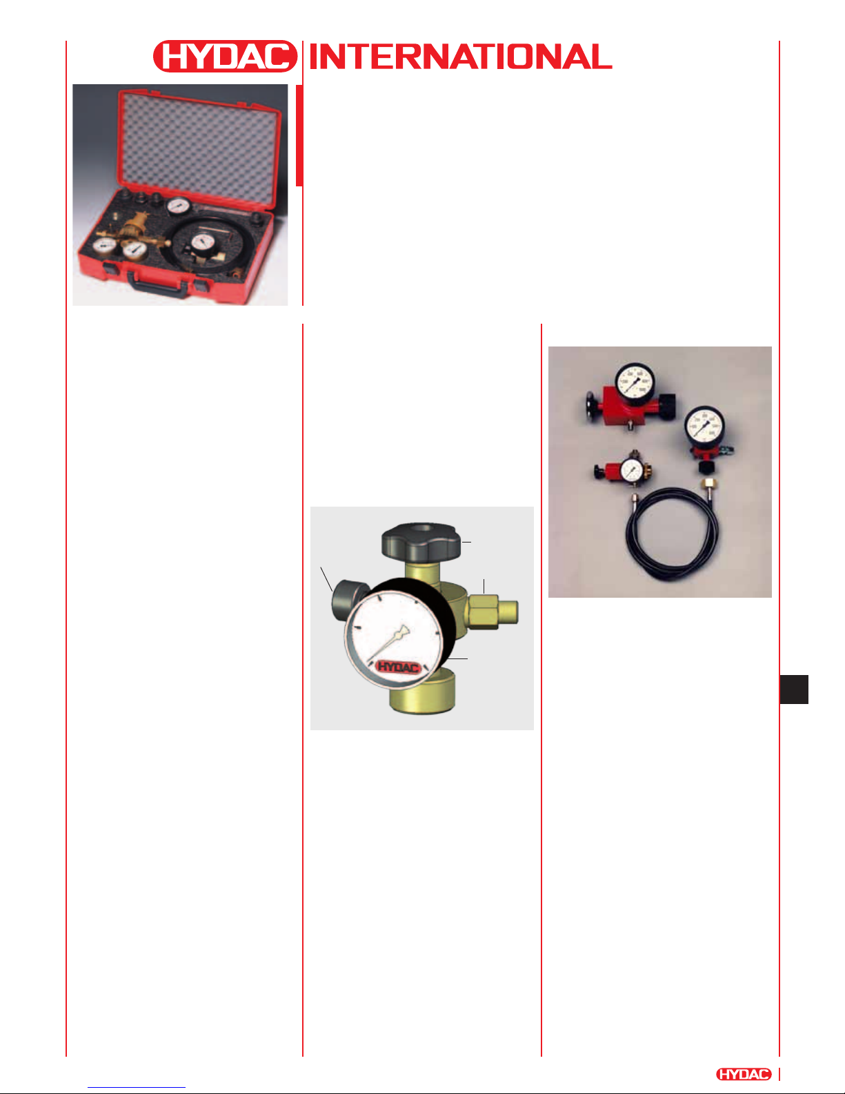
The HYDAC charging and testing unit
FPU-1 is used to charge accumulators with
nitrogen or to check or to change the
existing pre-charge pressure in
accumulators.
For this purpose the charging and testing
unit is screwed onto the gas valve of the
hydraulic accumulator and connected via a
hose to a commercial nitrogen bottle.
If the nitrogen pressure is only to be
checked or reduced, the charging hose
does not need to be connected. The unit
has a screw-type tting with a built-in
gauge, check valve and a spindle for
opening the accumulator gas valve to
control the pressure.
HYDAC piston and diaphragm
accumulators can be charged and checked
without the need for adapters. Bladder
accumulators, however, require an A3
adapter.
Please read the Operating Manual!
No. 3.501.CE
Universal Charging
and Testing Unit FPU-1
for Bladder, Piston and Diaphragm
Accumulators
1.3. SPECIAL MODELS1.2. DESIGN
The HYDAC charging and testing unit
for bladder, piston and diaphragm
accumulators consists of:
z Valve body
z Spindle
z Check valve
z Release valve
z Pressure gauge
z Charging hose
z A3 adapter for bladder accumulators
Release valve
Spindle
Check valve
Pressure gauge
For higher pressures, the following special
models are available:
z FPS 600
for bladder accumulators up to 600 bar
max. pre-charge pressure (see technical
information 293715).
z FPK 600
for piston, diaphragm and
SB800-1.5 accumulators up to 600 bar
max. pre-charge pressure (see
technical information 297248).
z FPH 800
for high pressure bladder accumulators
up to 800 bar max. pre-charge pressure
(see technical information 242948).
The photo top left shows a possible order
option, including accessories.
Page 2
98
E 3.501.26/03.12
2. TECHNICAL SPECIFICATIONS
2.1. MODEL CODE
(also order example)
FPU-1 - 250 F 2,5 G2 A1 K
Universal charging
and testing unit
p
max
= 350 bar
Gauge indication range
0 - 10 bar 0 - 145 psi 10
0 - 25 bar 0 - 363 psi 25
0 - 100 bar 0 - 1450 psi 100
0 - 250 bar 0 - 3625 psi 250
0 - 400 bar 0 - 5800 psi 400
Charging hose
F = for 200 bar nitrogen bottle
with connection W24.32x1/14
(DIN 477, Part 1)
FM = for 300 bar nitrogen bottle
with connection M30x1.5
(DIN 477, Part 5 up to April 2002)
FW = for 300 bar nitrogen bottle
with connection W30x2
(DIN 477, Part 5 from April 2002)
Length of charging hose
2.5 = 2.5 m
4.0 = 4 m
Special lengths on request
Adapter G for nitrogen bottles
See table, Point 3.6.
Adapter A
A1 = M16x1.5
A2 = 5/8 - 18 UNF
A3 = 7/8 - 14 UNF
A4 = 7/8 - 14 UNF
A5 = M8x1
A6 = G 3/4 A
A7 = G 1/4
A8 = G 3/4
A9 = Vg 8
A10 = 7/8 - 14 UNF
A11 = M16x2
A12 = M16x2
D4 = 5/8 - 18 UNF
(Part no. 366374)
other adapters on request
Protective case
Accessories - please give full details when ordering
(see Point 4.)
(A3 is supplied as standard)
1.4. TESTING INTERVALS
In general, nitrogen losses on HYDAC hydraulic accumulators are
very low. However, a regular check of the gas lling pressure is
recommended to prevent the piston from hitting the end cap, or
the bladder or diaphragm from becoming too deformed if there is
a drop in the pressure p
0.
The pre-charge pressure p0 as shown on the label or the
accumulator body, must be re-set after every new installation or
repair and then checked at least once during the following week. If
no nitrogen loss is detected, a further check should be made after
approx. 4 months. If after this period no change in the pressure is
found, a yearly check should be sufcient.
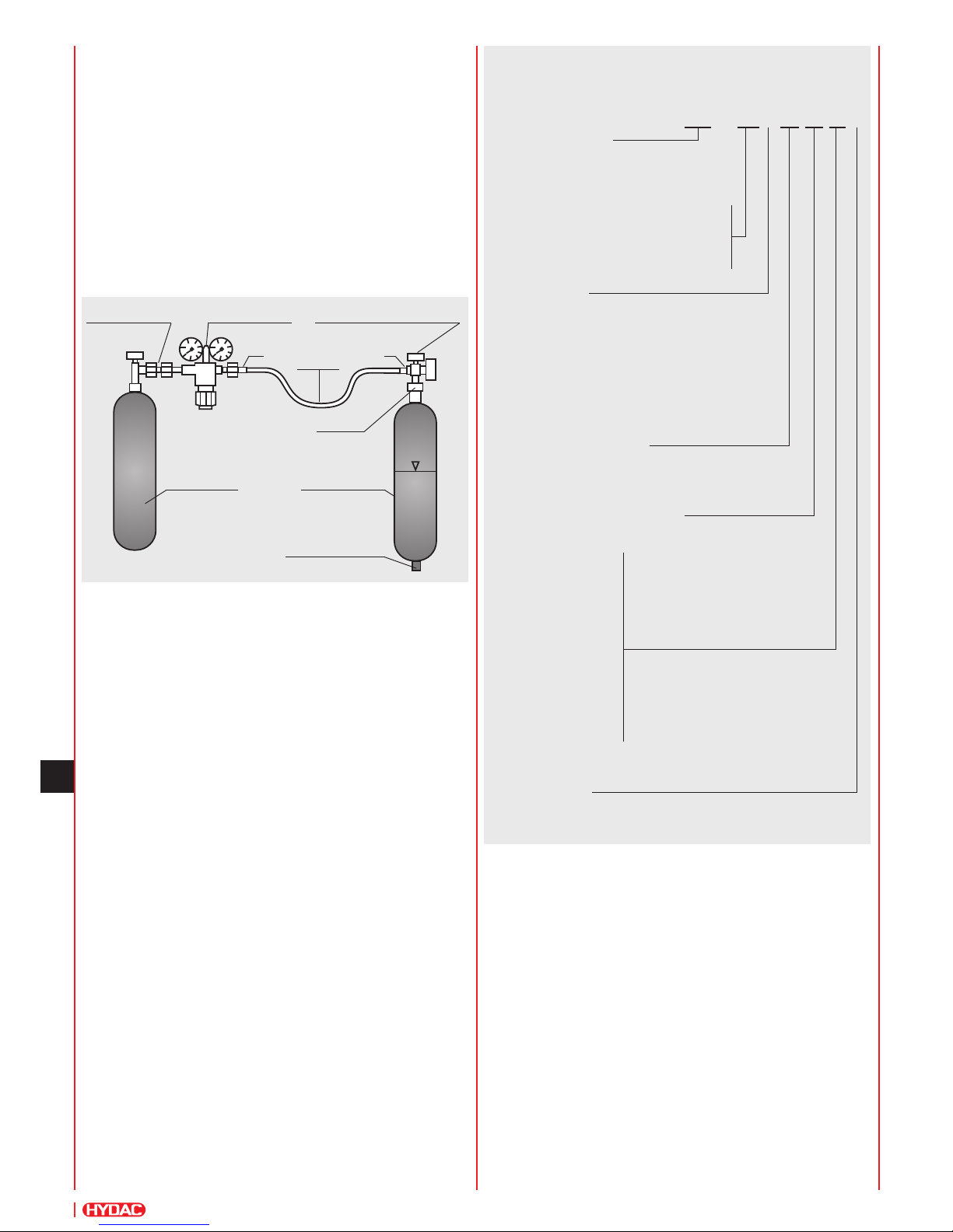
1.5. SCHEMATIC DRAWING
Fluid connection
Nitrogen bottle
Hydraulic
accumulator
Adapter A
MG1
Charging
hose
Adaptor G Pressure reducer Charging and testing unit FPU-1
N
2
N
2
Page 3
99
E 3.501.26/03.12
3. DIMENSIONS
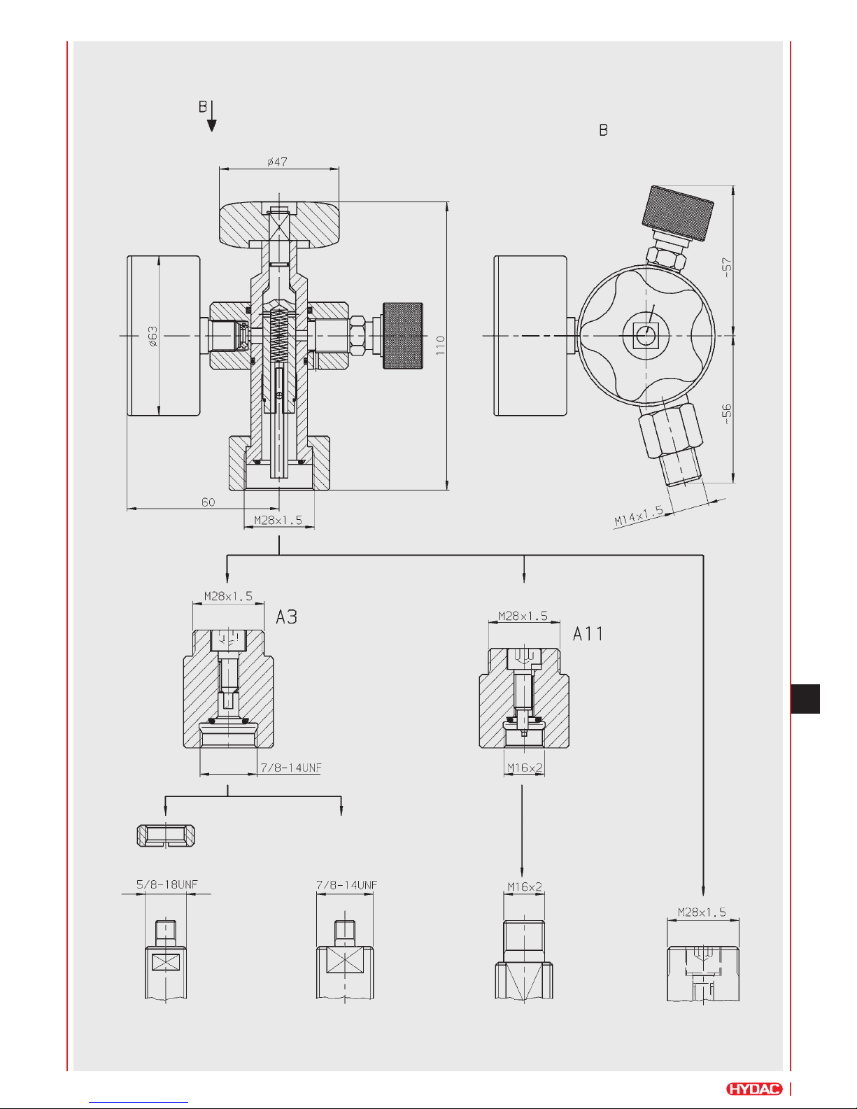
3.1. CHARGING AND TESTING UNIT FPU-1 WITH ADAPTER FOR HYDAC ACCUMULATORS
Bladder accumulators
330-0.5 / 400-0.5
Bladder accumulators
≥ 1l
Gas valve
to ISO 10945
Piston and diaphragm
accumulators
D4 Adapter
Page 4
100
E 3.501.26/03.12
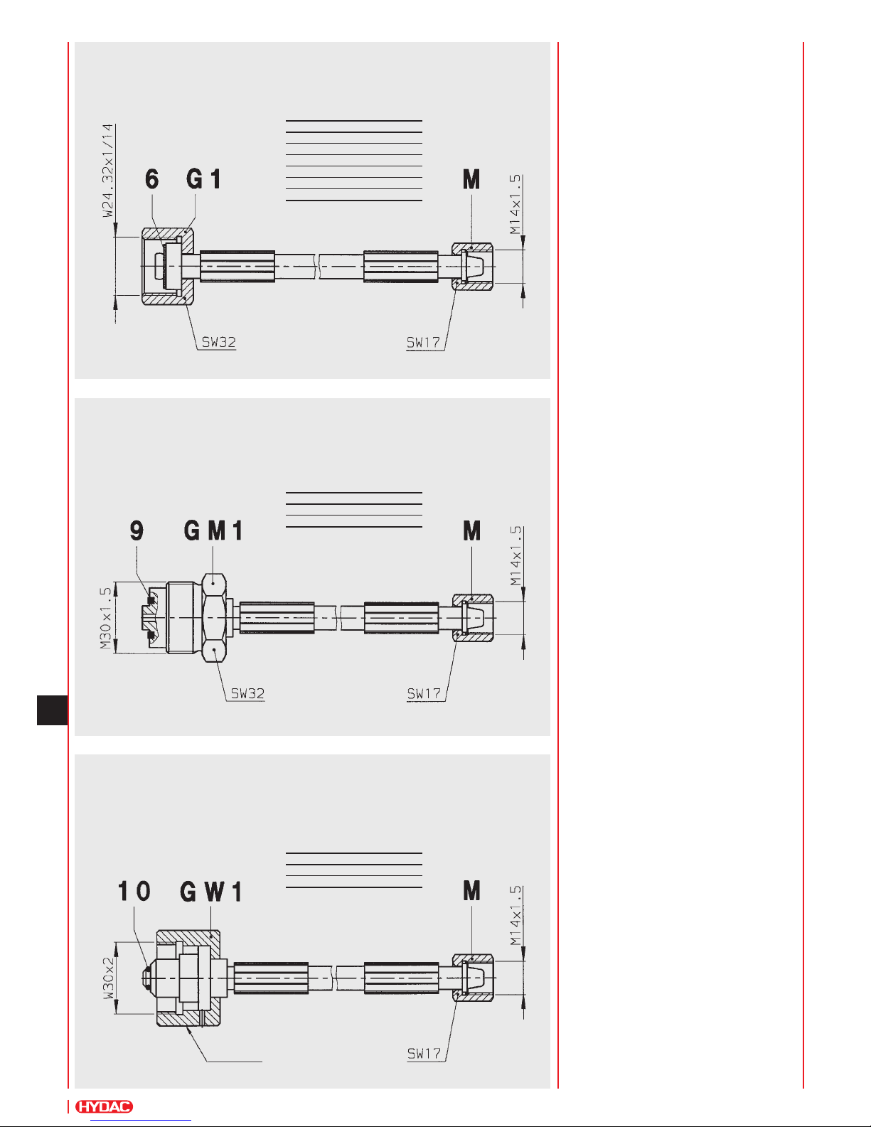
3.2. CHARGING HOSE F
(200 bar nitrogen bottle - connection to DIN 477, Part 1)
Length Part no.
2.5 m 236514
4.0 m 236515
10.0 m 373405
15.0 m 2115552
20.0 m 2109765
28.0 m 2109574
3.3. CHARGING HOSE FM
(300 bar nitrogen bottle - connection to DIN 477, Part 5 up to April 2002)
Length Part no.
2.5 m 3019417
4.0 m 3019418
3.4. CHARGING HOSE FW
(300 bar nitrogen bottle - connection to DIN 477, Part 5 after April 2002)
Length Part no.
2.5 m 3019419
4.0 m 3019420
Charging hoses are suitable for
the particular maximum permitted
operating pressure marked on them and
10,000 charging processes.
(HYDAC charging hoses comply with
the EC Machinery Directive and with
DIN EN 982 and DIN EN 853 to 857)
knurl
Page 5
101
E 3.501.26/03.12
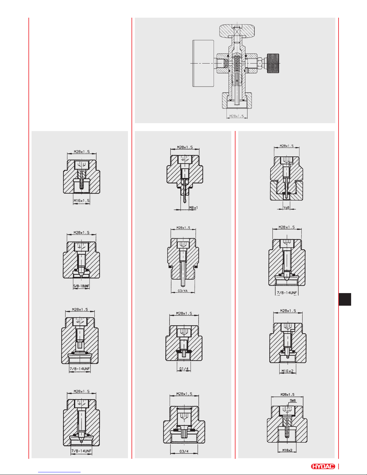
A1 (Part no. 361619)
A2 (Part no. 361605)
A3 (Part no. 291533)
A4 (Part no. 291536)
A5 (Part no. 291531)
A6 (Part no. 2108819)
A7 (Part no. 2110629)
A8 (Part no. 2124524)
A9 (Part no. 2128638)
A10 (Part no. 2128849)
A11 (Part no. 3018210)
A12 (Part no. 3203185)
3.3. ADAPTERS A1 TO A12
The universality of the FPU-1 is
guaranteed because as well as HYDAC
piston and diaphragm accumulators,
bladder accumulators can also be charged
and tested using the A3 adapter.
By using additional adapters other makes
of accumulator can also be charged and
tested.
Page 6
102
E 3.501.26/03.12
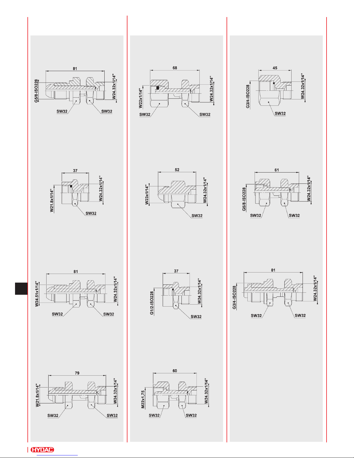
G 10 (Part no. 2103427)
G 11 (Part no. 3018678)
G 12 (Part no. 3195556)
G 6 (Part no. 2103423)
G 7 (Part no. 236377)
G 8 (Part no. 2103425)
G 9 (Part no. 241168)
G 2 (Part no. 236376)
G 3 (Part no. 2103421)
G 4 (Part no. 236374)
G 5 (Part no. 236373)
3.4. ADAPTERS
G2 TO G12
Page 7
103
E 3.501.26/03.12
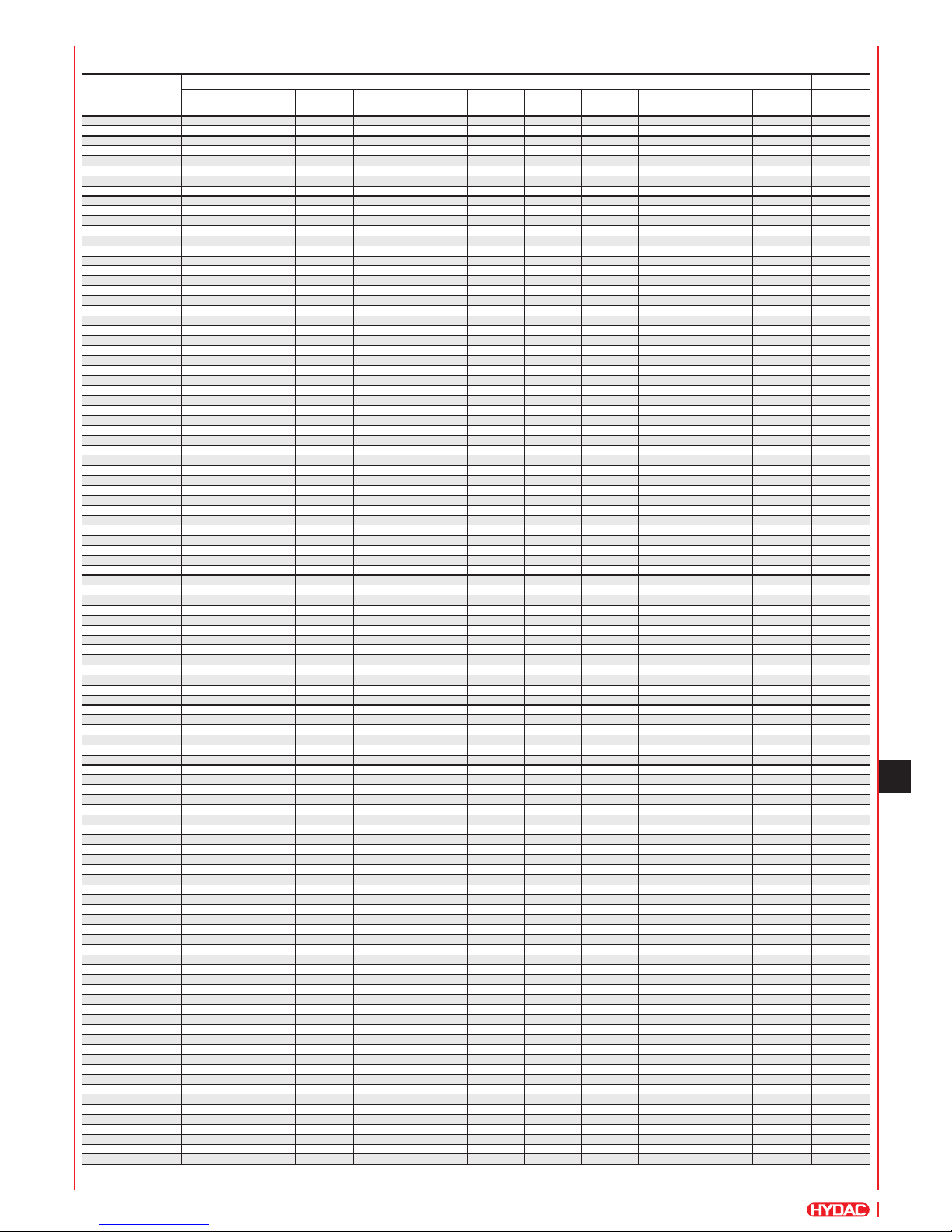
3.4.1 Schedule of countries
G adapters for nitrogen bottles from different countries.
Country Type / Part no.
G1
1)
G2 G3 G4 G5 G6 G7 G8 G9 G10 G11 G12
236376 2103421 236374 236373 2103423 236377 2103425 241168 2103427 3018678 3195556
Albania
z
Algeria
z
Argentina
z
Australia
z
Austria
z
Bahamas
z
Bahrain
z
Bangladesh
z
Barbados
z
Belgium
z
Bolivia
z
Botswana
z
Brazil
z
Bulgaria
z
Burma
z
Canada
z
Chile
z
China
z
Columbia
z
Costa Rica
z
Cyprus
z
Czech Republic
z
Denmark
z
Djibouti
z
Dominican Republic
z
Ecuador
z
Egypt
z
Ethiopia
z
Fiji
z
Finland
z
France
z
Gabon
z
Gambia
z
Germany
z
Ghana
z
Great Britain
z
Greece
z
Guatemala
z
Guinea
z
Guyana
z
Honduras
z
Hong Kong
z
Hungary
z
India
z
Indonesia
z
Iran
z
Iraq
z
Ireland
z
Israel
z
Italy
z
Ivory Coast
z
Jamaica
z
Japan
z
Jordan
z
Kenya
z
Korea
z
Kuwait
z
Lebanon
z
Libya
z
Malawi
z
Malaysia
z
Malta
z
Mauritius
z
Mexico
z
Morocco
z
Mozambique
z
Netherlands
z
New Zealand
z
Nigeria
z
Norway
z
Oman
z
Pakistan
z
Paraguay
z
Peru
z
Philippines
z
Poland
z
Portugal
z
Puerto Rico
z
Qatar
z
Romania
z
Russia
z
Saudi Arabia
z
Singapore
z
South Africa
z
Spain
z z
Sri Lanka
z
Sudan
z
Surinam
z
Swaziland
z
Sweden
z
Switzerland
z
Syria
z
Taiwan
z
Tanzania
z
Thailand
z
Trinidad/Tobago
z
Tunisia
z
Turkey
z
United Arab Emirates
z
Uruguay
z
USA
z
Venezuela
z
Vietnam
z
Yugoslavia
2)
z
Zambia
z
z = suggestion
1)
= already tted to hose
2)
= Bosnia, Herzegovina, Croatia, Macedonia, Slovenia
Page 8
104
E 3.501.26/03.12
4. ACCESSORIES
4.1. PROTECTIVE CASE
For storing the charging and testing unit
and adapters.
Different types of case are available,
depending on customer requirement.
FPU-1, standard model,
without case: approx. 1.4 kg
FPU-1, standard model,
with case: approx. 3.0 kg
4.2. GAS SAFETY VALVE
Provides protection by reducing the
pressure in a controlled way if pressure
exceeds the permitted level unexpectedly,
see catalogue section:
z Safety Equipment for
Hydraulic Accumulators
No. 3.552
4.3. ADAPTER D4
For screw connector D on bladder
accumulators < 1 l (see Point 3.)
4.5. PRESSURE REDUCER
For adjusting the required pre-charge pressure between the nitrogen bottle and the
accumulator.
4.5.1 Pressure reducer for 200 bar nitrogen bottles
Inlet: connection W24.32x1/12-DIN 477, Part 1
Outlet: male thread W24.32x1/14-DIN 477, Part 1
Bottle pressure [bar] Pressure after reducer [bar] Part no.
200 20 635409
200 100 635411
200 200 635412
4.5.2 Pressure reducer for 300 bar nitrogen bottles
Inlet: connection W30x2-DIN 477, Part 5
Outlet: male thread W24, 32x1/14-DIN 477, Part 5
Bottle pressure [bar] Pressure after reducer [bar] Part no.
300 20 6004020
300 100 6004021
300 200 6004022
300 270* 6004023
* if pressure after reducer > 200 bar, the outlet has a male thread W30x2-DIN 477, Part 5
Weight: 0.5 kg
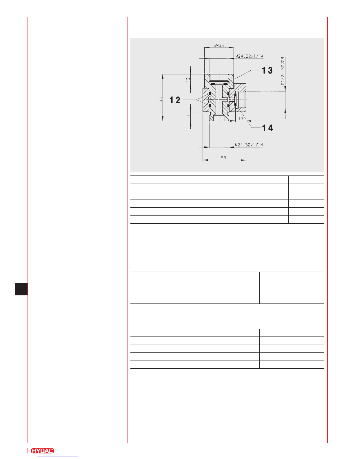
4.4. INTERMEDIATE PIECE GSV6-10-CE
Intermediate piece for installing the gas safety valve GSV6 between the 200 bar nitrogen
bottle and the charging and testing unit FPU-1.
Item Quantity Description Dimension Part no.
Intermediate piece GSV6-10-CE 242558
12 2 O-ring 20x2.5x2 601058
13 1 Seal ring 20x11.5x2 614706
14 1 Seal ring 14x8.5x2 612735
Seal kit for intermediate piece 2117287
Page 9

105
E 3.501.26/03.12
6. NOTE
The information in this brochure relates to
the operating conditions and
applications described.
For applications and operating conditions
not described, please contact the relevant
technical department.
Subject to technical modications.
5. SPARE PARTS, ADAPTERS AND TOOLS
5.1. SPARE PARTS
CHARGING AND TESTING UNIT FPU-1
Item Quantity Description Part no.
1 1 O-ring 6x1 601032
2 1 Seal ring 612730
3 1 Pressure gauge 0 - 10 bar
0 - 25 bar
0 - 100 bar
0 - 250 bar
0 - 400 bar
635139
635140
635141
635142
635143
5 1 O-ring 15x2 601049
6 1 Seal ring 601456
7 1 O-ring 11x2 601043
8 1 O-ring 9x2 601040
9 1 O-ring 11x2.5 603681
10 1 O-ring 5.7x1.9 6004009
Seal kit FPU-1 2117669
5.2. ADAPTERS
Description Part no.
Seal kit for adapters A1-12 3269153
5.3. TOOLS
Description Part no.
Wrench 14x15 1011065
Allen key SW6 1005164
Torque wrench 3136470
Valve tool for gas valve 616886
HYDAC Technology GmbH
Industriegebiet
66280 Sulzbach/Saar, Germany
Tel.: +49 (0) 68 97 / 509 - 01
Fax: +49 (0) 68 97 / 509 - 464
Internet: www.hydac.com
E-Mail: [email protected]
Page 10

106
E 3.501.26/03.12
 Loading...