

Page 1
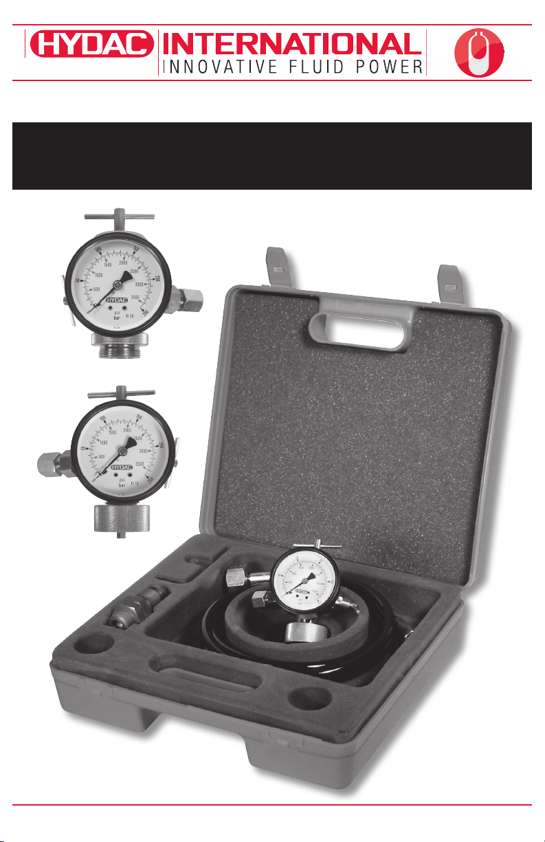
Accumulators
Charging & Gauging Units
FPK / FPS Operating Manual
1.877.GO.HYDAC www.HYDACusa.com 1.888.99.HYDAC www.HYDAC.ca
PN#02068202 • ACU1107-1367 / 09.11
Page 2
ACCUMULATORS
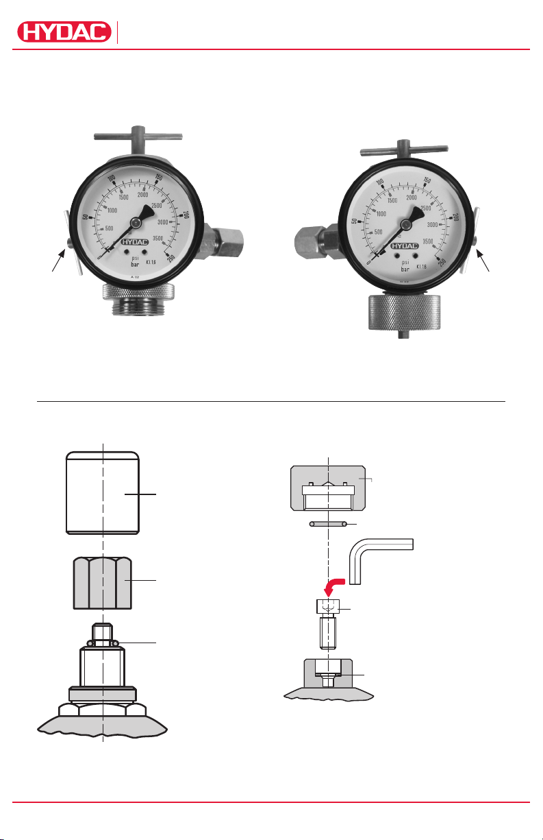
FPS
Manual
Bleed
Valve
Version 4
FPK
T-Handle T-Handle
Check
Valve
Manual
Bleed
Valve
Cap Nut Cap Nut
Figure 1
Version 1
PN#02068202 • ACU1107-1367 / 09.11
2
Charging & Gauging Units
valve
protection
cap
(where applicable)
Valve
seal cap
O-ring
Figure 2
Valve protection cap
(where applicable)
O-ring (where applicable)
Allen Wrench 6 mm
(to be used to crack open M8 SHCS.
T handle on FPK Charging is not robust
enough to overcome recommended torque)
Socket Head
Cap Screw (M8)
Seal ring
Page 3

ACCUMULATORS
General Warning!
Hydraulic accumulators are pressurized
vessels and only qualified technicians
should perform maintenance. For additional
information refer to HYDAC Operating
and Installation Instructions and HYDAC
Maintenance Instructions. Read all
instructions thoroughly before before
beginning any type of service or repair.
Tools Required
1. Gas Valve Core Tool.
2. Torque Wrenches.
3. Wrench(es).
Intervals Between Checking
Gas Precharge Pressure
The proper gas precharge pressure should
be set after each new installation or repair
by following the instructions under the
Operating and Installation Instructions
below. It should be rechecked at least once
during the first week of operation. If there
is no loss of gas precharge pressure, it
should be rechecked again in 3 to 4 months.
Thereafter, it should be checked at least
once a year. Recharge accumulator when
necessary.
Temperature Effect
To ensure that the recommended gas
precharge pressure is maintained,
even at relatively low of high operating
temperatures, the gas precharge pressure
should be adjusted for temperature. The
formula below relates the precharge
temperature (T0) to the operating
temperature (T).
Fahrenheit
P
= P
0,T0
Celsius
P
0,T0
T0 = precharge temperature
T2 = maximum operating temperature
P
0,T0
precharge temperature
P
0,T 2
x (T0 + 460) / (T2 + 460)
0,T 2
= P
x (T0 + 273) / (T2 + 273)
0,T 2
= gas precharge pressure at
= gas precharge pressure at
maximum operating temperature
Operating and
Installation Instruction
Preparation
To check the gas precharge pressure in
an accumulator, it must first be isolated
from the system shut off, and all hydraulic
pressure relieved.
HYDAC gas valve version 4 (se e fig. 2)
Unscrew the valve protection cap (where
applicable) and the valve seal cap.
HYDAC gas valve version 1 (se e fig. 2)
Unscrew the valve protection cap (where
applicable). Slightly loosen the socket head
cap screw with a 6 mm Allen wrench (approx.
1/6 turn, see fig. 2).
FPS Unit
Prior to connecting the charging and
gauging unit to an accumulator, turn
T-handle counter-clockwise until resistance
is felt. Close manual bleed valve by
hand tightening. Connect the unit to the
accumulator by screwing cap nut onto
HYDAC gas valve version4; hand tighten
(see fig. 1).
FPK Unit
Prior to connecting the charging and
gauging unit to an accumulator, close
manual bleed valve by hand tightening.
Connect the unit to the accumulator by
screwing cap nut onto HYDAC gas valve
version 1; hand tighten
(see fig. 1).
FPK Unit (with adapter FPK/SB)
Prior to connecting the charging and
gauging unit to an accumulator, take
adapter FPK /SB and unscrew the socket
head cap screw 3 full turns counter
clockwise using the 6 mm Allen wrench.
This is done to prevent gas valve damage
and leakage upon installation. Screw the
adapter FPK /SB onto HYDAC gas valve
version 4, hand tighten. Close manual bleed
valve on the FPK unit hand tight. Connect
FPK unit to adapter FPK/SB by screwing
cap nut onto the adapter; hand tighten.
Charging & Gauging Units
PN#02068202 • ACU1107-1367 / 09.11
3
Page 4

ACCUMULATORS
Checking Gas
Precharge Pressure
Connect the appropriate charging and
gauging unit to the accumulator following
the instructions under “Preparation” (see
page 2). Note: Temperature affects the
gas precharge pressure, please refer to
“Temperature Ef fect” (see page 2).
FPS Unit
Turn T-handle “A” clockwise a maximum of
3 full turns from the full counterclockwise
position. The gauge needle should indicate
the existing gas precharge pressure. If there
is no gas precharge pressure indicated
or if it is too low or too high, please follow
instructions under the appropriate section,
either “Pressure Release” (see below)
or “Charging” (to right). If desired gas
precharge pressure registers, please follow
the instructions under “Removal of Charging
and Gauging Unit” (see page 5).
FPK Unit
Turn T-handle counter clockwise a
maximum of 3 full turns. The gauge needle
should indicate the existing gas precharge
pressure. If there is no gas precharge
pressure indicated or if it is too low or
too high, please follow instructions under
the appropriate section, either “Pressure
Release” (see page 3) or “Charging” (see
page 3). If desired gas precharge pressure
registers, please follow the instructions
under “Removal of Charging and Gauging
Unit” (see page 4).
Pressure Release
With the appropriate charging and gauging
unit attached as previously described,
gas precharge pressure can be released
by carefully opening manual bleed valve.
Release the gas precharge pressure very
slowly until the desired gas precharge
pressure is reached (this insures that the
gas temperature does not fluctuate greatly,
providing and accurate gas precharge
pressure). Close the manual bleed valve.
Allow the gas precharge pressure to
stabilize. (5 to 10 minute s) recheck, adjust if
required. Once the desired gas precharge
pressure is reached, please follow the
instructions under “Removal of Charging
and Gauging Unit” (see page 5).
Charging
Warning!
Never use oxygen or air - this could
cause an explosion! Use dry nitrogen or
other recommended gases.
HYDAC recommends the use of a pressure
regulator on the commercially available
nitrogen bottle to regulate pressure to the
charging and gauging unit.
Note: Full nitrogen pressure may damage
the gauge. Connect the charging hose to
a commercially available nitrogen bottle
by means of the G4 adapter (other adapters
are available, check with factory for type); the
adapter connects to the cap screw “G1”.
Connect cap nut of the charging hose to
check valve of the charging and gauging
unit (see fig. 1). Connect the appropriate
charging and gauging unit to the
accumulator by following the instructions
previously described (see page 2).
Initial Charging
When charging an accumulator that has no
initial gas precharge, allow 20 to 30 minutes
for the gas temperature and thus pressure
to stabilize. Recheck the gas precharge
pressure and adjust if necessary.
FPS Unit
Turn T-handle clockwise 3 full turns.
Proceed to “Filling”.
FPK Unit
Turn T-handle counter clockwise 3 full turns.
Proceed to “Filling”.
FPK Unit (with adapter FPK/SB)
Turn T-handle clockwise 3 full turns.
Proceed to “Filling”.
PN#02068202 • ACU1107-1367 / 09.11
4
Charging & Gauging Units
Page 5

ACCUMULATORS
Pressure Increase
When charging an accumulator that has
an existing gas precharge, allow 5 to 10
minutes for the gas temperature and thus
pressure to stabilize.
FPS Unit
Turn T-handle clockwise until the gauge
needle begins to deflect, then turn it another
full turn. Proceed to “Filling”.
FPK Unit
Turn T-handle counter clockwise until the
gauge needle begins to deflect, then turn it
another full turn. Proceed to “Filling”.
FPK Unit (with adapter FPK/SB)
Turn T-handle clockwise until the gauge
needle begins to deflect, then turn it another
full turn. Proceed to “Filling”.
Filling
Open the shut-off valve on the commercially
available nitrogen bottle and slowly fill the
accumulator with dry nitrogen gas.
Precharge very slowly until the pressure
in the accumulator reaches 100 psi. Once
100 psi is reached, the charging rate can
increase. Charging too quickly may damage
the accumulator.
Note: The gauge registers the line pressure,
not necessarily the accumulator pressure
while charging.
After allowing the appropriate time for
the gas temperature and thus pressure to
stabilize, adjust the gas precharge pressure
as required, refer to “Pressure Increase” (see
page 4) or “Pressure Release” (see page 3).
Once the desired gas precharge pressure
is reached close the shutoff valve on the
commercially available nitrogen bottle.
Remove the charging and gauging unit from
the gas valve as described under “Removal
of Charging and Gauging Unit” (see page 5).
Removal of Charging and
Gauging Unit
Close the shut-off valve on the commercially
available nitrogen bottle before removing
the charging and gauging unit.
FPS Unit
Turn T-handle counter clockwise until
resistance is felt to close the gas valve.
Open manual bleed valve to relieve pressure
in the charging and gauging unit. Proceed to
“Disconnecting”.
FPK Unit
Turn T-handle clockwise until resistance
is felt to close the socket head cap screw,
hand tighten. Open manual bleed valve to
relieve pressure in the charging and gauging
unit. Proceed to “Disconnecting”.
FPK Unit (with adapter FPK/SB)
Turn T-handle counter clockwise until
resistance is felt to close the gas valve.
Open manual bleed valve to relieve pressure
in the charging and gauging unit. Proceed to
“Disconnecting”.
Disconnection
Unscrew the charging and gauging unit
from the gas valve. Note: For FPK unit with
adapter FPK /SB it may be necessary to
loosen the connection between cap nut
and the adapter to remove the charging
and gauging unit. Check for leaks. None are
permissible.
Completion
HYDAC gas valve version 1 (se e fig. 1)
Tighten socket head screw cap to 20 Nm
(15 lb-ft), and screw on valve protection cap
(where applicable); hand tighten.
HYDAC gas valve version 4 (se e fig. 1)
Screw on valve seal cap torquing to 30 Nm
(22 lb-ft), and valve protection cap (where
applicable); hand tighten.
Charging & Gauging Units
PN#02068202 • ACU1107-1367 / 09.11
5
Page 6

Spare Parts
ACCUMULATORS
Item Description Part No.
9 O-Ring 00 601032
10 Seal-Ring 00 6 012 28
11 Gauge (select pressure range below)
12 Check Valve 00610004
13 Manual Bleed Valve 00236445
23
- 2.5m Hose 00236514
- 4m Hose 00 236 515
- 10m Hose 00373405
- ADAPTER G4 02068737
PN#02068202 • ACU1107-1367 / 09.11
6
- ADAPTER A3 (FPK/SB) 00291533
- O-Ring - ADAPTER A3 (FPK/SB) 00 601964
Charging & Gauging Units
10 (0 to 145 psi) 00606759
25 (0 to 350 psi) 00606760
100 (0 to 1400 psi) 00606761
250 (0 to 3500 psi) 00606762
400 (0 to 5800 psi) 00606763
O-Ring - FPS 00626488
O-Ring - FPK 006 01049
Page 7

ACCUMULATORS
A9
A
1
A5
A Adapters (Gauge to Accumulator)
PN 00291531
M28x1.5
A6
PN 02108819
M28x1.5
A7
PN 02110629
M28x1.5
M8x1
G3/4A
PN 00361619
M28x1.5
M16x1.5
A2
PN 00361605
M28x1.5
5/8-18UNF
A3 (ADAPTER FPK/SB)
PN 00291533
M28x1.5
PN 02128638
M28x1.5
A10
PN 02128849
A11
PN 03018210
M28x1.5
7/8-14UNF
M28x1.5
Vg8
7/8-14UNF
A4
PN 00291536
M28x1.5
7/8-14UNF
A8
PN 02124524
M28x1.5
G1/4
G3/4
M16x2
A12
PN 03930191
M28x1.5
M16x2
(Test Point)
Charging & Gauging Units
PN#02068202 • ACU1107-1367 / 09.11
7
Page 8

G Adapters (Charging to Accumulator)
G2
PN 00236376
Australia
Argentina
Great Britain
Vietnam
Others
G3
PN 02103421
Egypt
Lebanon
Israel
Others
seal ring A6x10
G5/8 - ISO 228
SW 32
37
W21.8x1/14"
SW 32
81
SW 32
W24.32x1/14"
G7
PN 00236377
Korea
W24.32x1/14"
G8
PN 02103425
Brazil
Chile
Columbia
Others
W23x1/14"
G1/2 - ISO 228
52
SW 32
W24.32x1/14"
40
W24.32x1/14"
SW 32
G4
PN 02068737
USA
Canada
Puerto Rico
W24.5x1/14"
G5
PN 00236373
Italy
W21.8x1/14"
G6
PN 02103423
Japan
W22x1/14"
Charging Hoses
Germany
Poland
Others
G1
81
seal ring A6x10
SW 32
79
seal ring A6x10
SW 32
68
seal ring A6x10
SW32
SW 32
SW 32
SW 32SW 32
G9
PN 00241168
Taiwan
W24.32x1/14"
G10
PN 02103427
Russia
Trinidad
Tobago
Venezeula
W24.32x1/14"
G11
PN 03018678
China
W24.32x1/14"
seal ring A6x10
M22x1.5
SW 30
ISO 228-G 3/4"
seal ring A6x10
G5/8-ISO228
SW 32
58
W24.32x1/14"
SW 32
45
SW 36
W24.32x1/14"
64
SW 32
W24.32x1/14"
M
M14x1.5
W24.32x1/14"
© Copyright 2011 HYDAC CORPORATION • FPK/FPS Operating Manual PN#02068202 • ACU1107-1367
1.877.GO.HYDAC www.HYDACusa.com 1.888.99.HYDAC www.HYDAC.ca
PN#02068202 • ACU1107-1367 / 09.11
 Loading...