

Hydac FPK, FPS Operating Manual
Accumulators
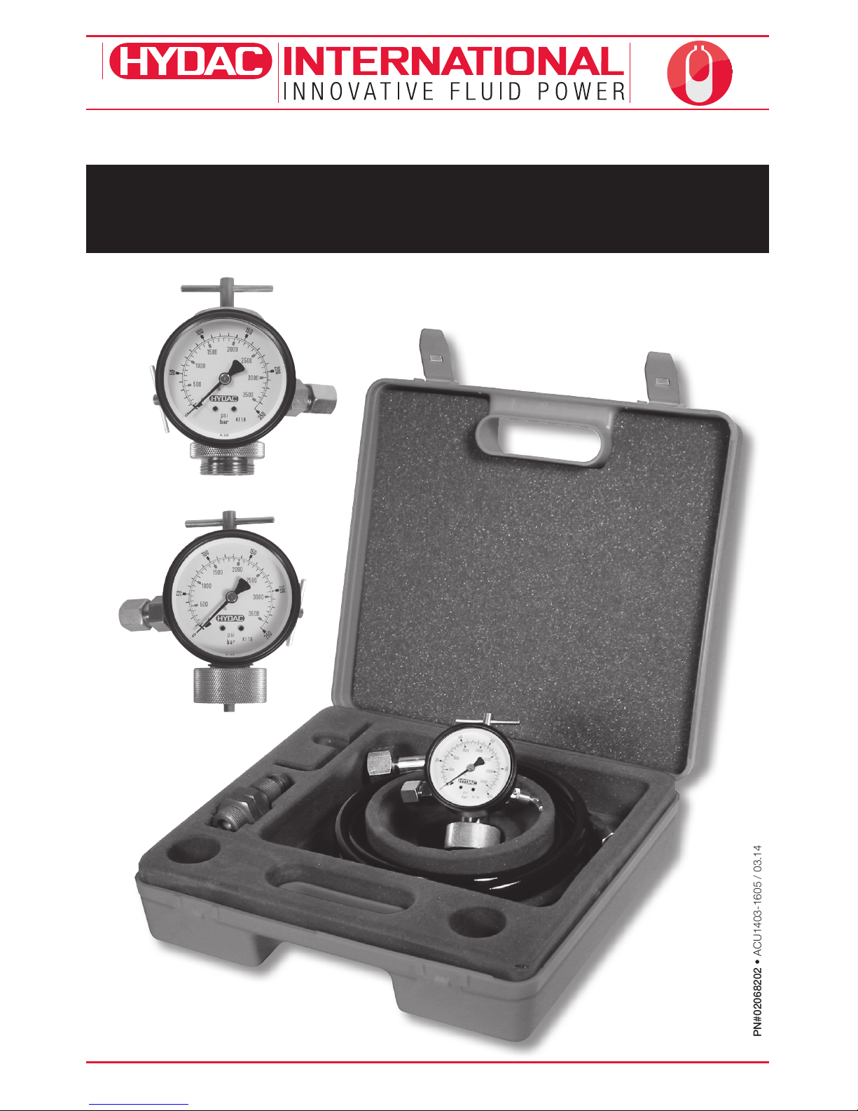
Charging & Gauging Units
FPK / FPS Operating Manual
1.877.GO.HYDAC www.HYDACusa.com 1.888.99.HYDAC www.HYDAC.ca
PN#02068202 • ACU1403-1605 / 03.14
2
Charging & Gauging Units
PN#02068202 • ACU1403-1605 / 03.14
ACCUMULATORS
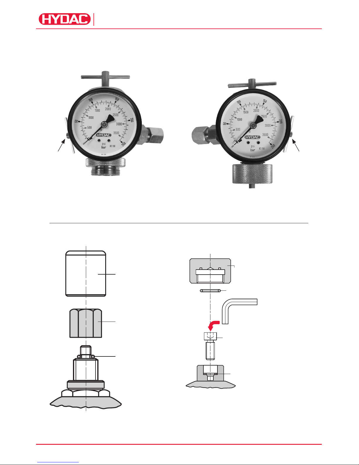
FPS
Version 4
FPK
Version 1
valve
protection
cap
(where applicable)
Valve
seal cap
O-ring
Allen Wrench 6 mm
(to be used to crack open M8 SHCS.
T handle on FPK Charging is not robust
enough to overcome recommended torque)
Valve protection cap
(where applicable)
O-ring (where applicable)
Socket Head
Cap Screw (M8)
Seal ring
T-Handle T-Handle
Check
Valve
Cap Nut Cap Nut
Manual
Bleed
Valve
Manual
Bleed
Valve
Figure 1
Figure 2

3
Charging & Gauging Units
PN#02068202 • ACU1403-1605 / 03.14
ACCUMULATORS
General Warning!
Hydraulic accumulators are pressurized
vessels and only qualified technicians
should perform maintenance. For additional
information refer to HYDAC Operating
and Installation Instructions and HYDAC
Maintenance Instructions. Read all
instructions thoroughly before before
beginning any type of service or repair.
Tools Required
1. Gas Valve Core Tool.
2. Torque Wrenches.
3. Wrench(es).
Intervals Between Checking
Gas Precharge Pressure
The proper gas precharge pressure should
be set after each new installation or repair
by following the instructions under the
Operating and Installation Instructions
below. It should be rechecked at least once
during the first week of operation. If there
is no loss of gas precharge pressure, it
should be rechecked again in 3 to 4 months.
Thereafter, it should be checked at least
once a year. Recharge accumulator when
necessary.
Temperature Effect
To ensure that the recommended gas
precharge pressure is maintained,
even at relatively low of high operating
temperatures, the gas precharge pressure
should be adjusted for temperature. The
formula below relates the precharge
temperature (T0) to the operating
temperature (T).
Fahrenheit
P
0,T 0
= P
0,T 2
x (T0 + 460) / (T2 + 460)
Celsius
P
0,T 0
= P
0,T 2
x (T0 + 273) / (T2 + 273)
T0 = precharge temperature
T2 = maximum operating temperature
P
0,T 0
= gas precharge pressure at
precharge temperature
P
0,T 2
= gas precharge pressure at
maximum operating temperature
Operating and
Installation Instruction
Preparation
To check the gas precharge pressure in
an accumulator, it must first be isolated
from the system shut off, and all hydraulic
pressure relieved.
HYDAC gas valve version 4 (see fig. 2)
Unscrew the valve protection cap (where
applicable) and the valve seal cap.
HYDAC gas valve version 1 (see fig. 2)
Unscrew the valve protection cap (where
applicable). Slightly loosen the socket head
cap screw with a 6 mm Allen wrench (approx.
1/6 turn, see fig. 2).
NOTE: In order to connect the charging
hose to the FPK/FPS charging unit body,
the small ferrule must first be removed.
FPS Unit
Prior to connecting the charging and
gauging unit to an accumulator, turn
T-handle counter-clockwise until resistance
is felt. Close manual bleed valve by
hand tightening. Connect the unit to the
accumulator by screwing cap nut onto
HYDAC gas valve version4; hand tighten
(see fig. 1).
FPK Unit
Prior to connecting the charging and
gauging unit to an accumulator, close
manual bleed valve by hand tightening.
Connect the unit to the accumulator by
screwing cap nut onto HYDAC gas valve
version 1; hand tighten
(see fig. 1).
FPK Unit (with adapter FPK/SB)
Prior to connecting the charging and
gauging unit to an accumulator, take
adapter FPK/SB and unscrew the socket
head cap screw 3 full turns counter
clockwise using the 6 mm Allen wrench.
This is done to prevent gas valve damage
and leakage upon installation. Screw the
adapter FPK/SB onto HYDAC gas valve
version 4, hand tighten. Close manual bleed
valve on the FPK unit hand tight. Connect
FPK unit to adapter FPK/SB by screwing
cap nut onto the adapter; hand tighten.
 Loading...