

Page 1

FluidControl Unit
FCU 1310
Operating and maintenance instructions
English (translation of original instructions)
Valid from firmware version V 3.00 up
Valid from series no. (S/N) 0002S01831K0001000
Keep for future reference.
Document No.: 3371346f
Page 2

Imprint
HYDAC FILTER SYSTEMS GMBH
Postfach 1251
66273 Sulzbach / Saar
Germany
Phone:
+49 6897 509 01
Fax:
+49 6897 509 9046
E-mail:
filtersystems@hydac.com
Homepage:
www.hydac.com
Court of Registration:
Saarbrücken, HRB 17216
Executive director:
Mathias Dieter,
Mr. Günter Harge
c/o HYDAC International GmbH, Industriegebiet, 66280 Sulzbach / Saar
Phone:
+49 6897 509 1511
Fax:
+49 6897 509 1394
E-mail:
guenter.harge@hydac.com
Imprint
Publisher and responsible for the content:
Dipl.Kfm. Wolfgang Haering
Documentation representative
© HYDAC FILTER SYSTEMS GMBH
All rights reserved. No part of this work may be reproduced in any form (print,
photocopy or by other means) or processed, duplicated or distributed using
electronic systems without the written consent of the publisher.
These documents have been created and inspected with the greatest care.
However, errors cannot be ruled out completely.
Technical specifications are subject to change without notice.
FCU1310
BeWa FCU1310 V300 3371346f en-us 2017-01-27.docx 2017-01-27
en(us)
Page 2 / 124
Page 3

Content
Content
Imprint ............................................................................................................ 2
Documentation representative .................................................................... 2
Content .......................................................................................................... 3
What's New — Changes to the manual ....................................................... 7
Preface ........................................................................................................... 8
Safety information ...................................................................................... 10
Technical Support ........................................................................................ 8
Modifications to the Product ........................................................................ 8
Warranty ...................................................................................................... 8
Using the documentation ............................................................................. 9
Hazard symbols ......................................................................................... 10
Signal words and their meaning in the safety information and
instructions ................................................................................................ 11
Structure of the safety information and instructions ................................... 12
Observe regulatory information ................................................................. 12
Proper/Designated Use ............................................................................. 13
Periodic intermittent duty - operating mode S3, (as per DIN EN
60034-1 / DIN VDE 0530, part 1) ........................................................... 14
Improper Use or Use Deviating from Intended Use ................................... 15
Qualifications of personnel / target group .................................................. 16
Wear personal protection equipment ......................................................... 17
Stoppage in an emergency (EMERGENCY STOP) ................................... 17
FCUOpening/Closing .................................................................................. 18
FCUtransporting ......................................................................................... 19
FCUstoring .................................................................................................. 20
Decoding the model code label ................................................................. 21
Checking the scope of delivery ................................................................. 23
What can the product do? .......................................................................... 24
Counting contaminant particles ................................................................. 25
How the product works .............................................................................. 27
Overview of control panel/operating elements ........................................... 28
Dimensions ................................................................................................ 29
Hydraulic diagram ...................................................................................... 30
Using the BatteryPack (accessory) ........................................................... 31
Preparing the FCU for measurement ........................................................ 36
Connecting/Disconnecting the FCU electrically ......................................... 36
Plug in/Detach return hose ........................................................................ 37
FCU1310
BeWa FCU1310 V300 3371346f en-us 2017-01-27.docx 2017-01-27
en(us)
Page 3 / 124
Page 4
Content
Selecting the measurement location .......................................................... 38
Select the measurement method according to the pressure
involved ..................................................................................................... 39
Measuring up to max. 45 bar / 650 psi....................................................... 40
Measuring in the range 5 to 345 bar / 217 to 5000 psi .............................. 43
Measuring from unpressurized containers ................................................. 47
FCUoperating .............................................................................................. 49
Display and keypad elements .................................................................... 49
Clicking through the display ....................................................................... 51
- Display ............................................................................. 51
- Display ............................................................................. 52
Displaying measured variables .................................................................. 53
" " measured variable ........................................................................ 53
" " measured variable ....................................................................... 53
" " measured variable ....................................................................... 53
" " measured variable .................................................. 53
" " measured variable ......................................................... 53
Display service variables ........................................................................... 54
" " service variable ........................................................................... 54
" " service variable .......................................................................... 54
Select operating level / configuration menu ............................................. 55
Operate / Set up menu .............................................................. 56
– Setting date/time ............................................................. 57
- Set bus address ............................................................... 57
- Delete memory ................................................................ 58
- Set measuring time ............................................................. 58
– Select calibration type ........................................................ 59
– Reset to default settings.................................................. 59
- Cancel .............................................................................. 60
– Save data .............................................................................. 60
Operating/Setting measuring menu ........................................................... 61
– Record measurements .................................................... 62
- Display free memory ........................................................ 63
– Change name of measurement point .............................. 64
- Set temperature unit ........................................................ 65
- Cancel .............................................................................. 66
– Save data .............................................................................. 66
Performing measurements ........................................................................ 67
Reading internal measurement memory ................................................... 68
Read out measured values via DATA interface ......................................... 69
Connecting FCU with a CSI-B-2 kit ........................................................ 69
FCU1310
BeWa FCU1310 V300 3371346f en-us 2017-01-27.docx 2017-01-27
en(us)
Page 4 / 124
Page 5

Content
Pins used on the DATA interface (HYDAC Sensor Interface –
HSI) ........................................................................................................ 69
Connecting FCU with HMG 510 / HMG 3000 / 4000 .............................. 70
Reading out USB interface measured values ............................................ 71
Copying measurements onto a USB data stick ...................................... 71
- Data transmission failed ..................................... 74
Reading out measured values via Bluetooth interface ............................... 75
Installing the Bluetooth USB adaptor ...................................................... 76
Guarantee and liability for the USB adapter ........................................ 76
Connecting/Linking the FCU via Bluetooth ............................................. 76
Evaluating measurement records ............................................................. 77
Measurement record directories according to measurement point ............ 77
Measurement report file names ................................................................. 77
Opening measurement reports .................................................................. 78
The measurements are shown as dates ................................................ 80
Evaluating/Reading measurement reports with FluMoS ......................... 82
Preparing the FCU for transport ................................................................ 83
Performing maintenance ............................................................................ 87
FCUcleaning .............................................................................................. 87
FCU flushing .............................................................................................. 88
Clean the suction strainer .......................................................................... 92
Checking the high pressure adapter .......................................................... 96
Cleaning / changing the strainer in the high pressure adapter ............... 97
Cleaning / changing the strainer in the high pressure adapter ............... 98
Identifying and interpreting status/error messages ................................ 99
Restarting/resetting .................................................................................. 103
Taking the FCU out of operation ............................................................. 103
Shutting down the FCU............................................................................ 103
FCUdisposing .......................................................................................... 103
Locating spare parts ................................................................................. 104
Selecting accessories .............................................................................. 105
Checking the measuring accuracy .......................................................... 107
FCUcalibrating ......................................................................................... 107
Technical Data........................................................................................... 108
Appendix ................................................................................................... 110
Model Code ............................................................................................. 110
Finding Customer Service / Service stations ........................................... 111
Germany .............................................................................................. 111
USA ...................................................................................................... 111
Australia ............................................................................................... 111
FCU1310
BeWa FCU1310 V300 3371346f en-us 2017-01-27.docx 2017-01-27
en(us)
Page 5 / 124
Page 6

Content
Brazil .................................................................................................... 112
Factory default settings............................................................................ 112
Overview / Definition of the cleanliness classes ...................................... 113
Cleanliness class acc. to ISO 4406:1999 ............................................. 113
ISO 4406 overview table ................................................................... 114
Difference between ISO4406:1987 and ISO4406:1999 ....................... 115
Cleanliness class acc. to SAE AS 4059 ............................................... 116
SAE AS 4059 overview table ............................................................ 116
Display cleanliness classes according to SAE Absolute particle
count larger than a defined particle size ............................................... 117
Specifying a cleanliness code for each particle size ......................... 117
Specifying the highest cleanliness code measured ........................... 117
Cleanliness class acc. to NAS 1638 ..................................................... 118
EC declaration of conformity .................................................................... 119
Explanation of terms and abbreviations ................................................... 121
Index ........................................................................................................ 122
FCU1310
BeWa FCU1310 V300 3371346f en-us 2017-01-27.docx 2017-01-27
en(us)
Page 6 / 124
Page 7

What's New — Changes to the manual
Index "a" from firmware version V 1.10
- Change to the items delivered
- Change of Bluetooth device name to "FCU1310"
Index "b" — from firmware version V 2.00
- Change to the items delivered
- "USB connection" chapter added
- Additions made to user interface chapters
- Additions made to "BatteryPack" chapter
Index "c"
- Index adapted
Index "d"
- Restrictions on use of fluid with flash point < 55 °C added
- Spare parts list adapted
- "Transporting FCU" section updated
- Filling the hose lines before measuring is no longer necessary.
Index "e" from firmware version V 3.00
- From firmware V3.00 / from series no. 0002S01831K0001000
- Update / corrections / reworking
- Index added
Index "f" from firmware version V 3.00
- Update / corrections / reworking
What's New — Changes to the manual
The index is featured on the cover sheet of the operating and maintenance
manual and in the lower left corner of each page after the part number.
FCU1310
BeWa FCU1310 V300 3371346f en-us 2017-01-27.docx 2017-01-27
en(us)
Page 7 / 124
Page 8

Preface
Fax:
+49 6897 509 9046
E-mail:
filtersystems@hydac.com
Preface
These operating instructions were made to the best of our knowledge.
Nevertheless and despite the greatest care, it cannot be excluded that
mistakes could have crept in. Therefore please understand that, in the
absence of any provisions to the contrary hereinafter, our warranty and
liability – for any legal reasons whatsoever – are excluded in respect of the
information in these operating instructions. In particular, we shall not be liable
for lost profit or other financial loss.
This exclusion of liability does not apply in cases of intent and gross
negligence. Moreover, it does not apply to defects which have been
deceitfully concealed or whose absence has been guaranteed, nor in cases
of culpable harm to life, physical injury and damage to health. If we
negligently breach any material contractual obligation, our liability shall be
limited to foreseeable damage. Claims due to Product Liability shall remain
unaffected.
Technical Support
If you have any questions, suggestions, or encounter any problems of a
technical nature, please don't hesitate to contact us. When contacting us,
please always include the model code, serial no. and part no. of the product:
Modifications to the Product
We would like to point out that changes to the product (e.g. purchasing
options, etc.) may result in the information in the operating instructions no
longer being completely accurate or sufficient.
After modification or repair work that affects the safety of the product has
been carried out on components, the product may not be returned to
operation until it has been checked and released by a HYDAC technician.
Please notify us immediately of any modifications made to the product
whether by you or a third party.
Warranty
For the warranty provided by us, please refer to the terms of delivery of
HYDAC FILTER SYSTEMS GMBH.
You will find these under www.hydac.com -> General Terms and Conditions.
FCU1310
BeWa FCU1310 V300 3371346f en-us 2017-01-27.docx 2017-01-27
en(us)
Page 8 / 124
Page 9
Preface
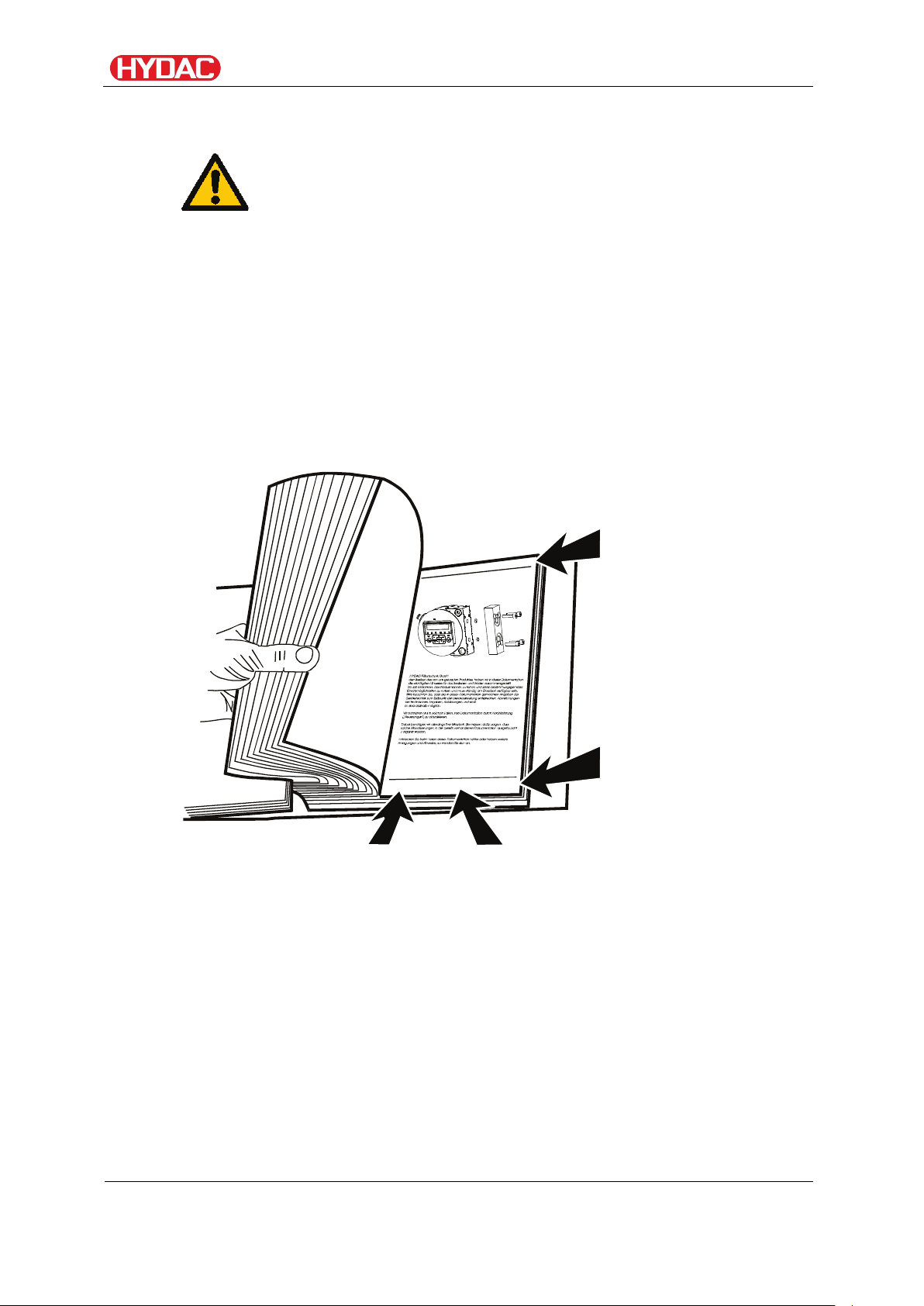
Note that the method described for locating specific information
de
HYDAC F
iltertechnik GmbH
BeWa 123456a de
Seite x
P
r
o
d
u
k
t
/
K
a
p
i
t
e
l
200x-xx-xx
Chapter description
Page number
Document language
Documentation no.
Using the documentation
does not release you from your responsibility of carefully reading
all these instructions prior to starting the unit up for the first time
and at regular intervals in the future.
What do I want to know?
I determine which topic I am looking for.
WHERE can I find the information I’m looking for?
The document has a table of contents at the beginning. I select the chapter
I'm looking for and the corresponding page number.
with index/
file name
The documentation number with its index enables you to order another copy
of the operating and maintenance instructions. The index is incremented
every time the manual is revised or changed.
FCU1310
BeWa FCU1310 V300 3371346f en-us 2017-01-27.docx 2017-01-27
en(us)
Edition date
Page 9 / 124
Page 10
Safety information
Safety information
The product was built according to the statutory provisions valid at the time of
delivery and satisfies current safety requirements.
Any residual hazards are indicated by safety information and instructions and
are described in the operating instructions.
Observe all safety and warning instructions attached to the product. They
must always be complete and legible.
Do not operate the product unless all the safety devices are present.
Secure the hazardous areas which may arise between the product and other
equipment.
Maintain the product inspection intervals prescribed by law.
Document the results in an inspection certificate and keep it until the next
inspection.
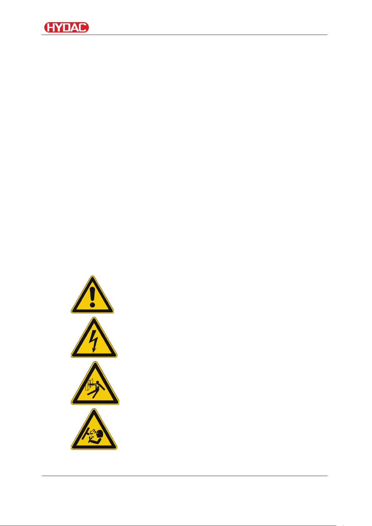
Hazard symbols
These symbols are listed for all safety information and instructions in these
operating instructions which indicate particular hazards to persons, property
or the environment.
Observe these instructions and act with particular caution in such cases.
Pass all safety information and instructions on to other users.
General hazard
Danger due to electrical voltage / current
Exposed electrical components
Danger of electrical shock
Danger due to operating pressure
FCU1310
BeWa FCU1310 V300 3371346f en-us 2017-01-27.docx 2017-01-27
en(us)
Page 10 / 124
Page 11
Safety information
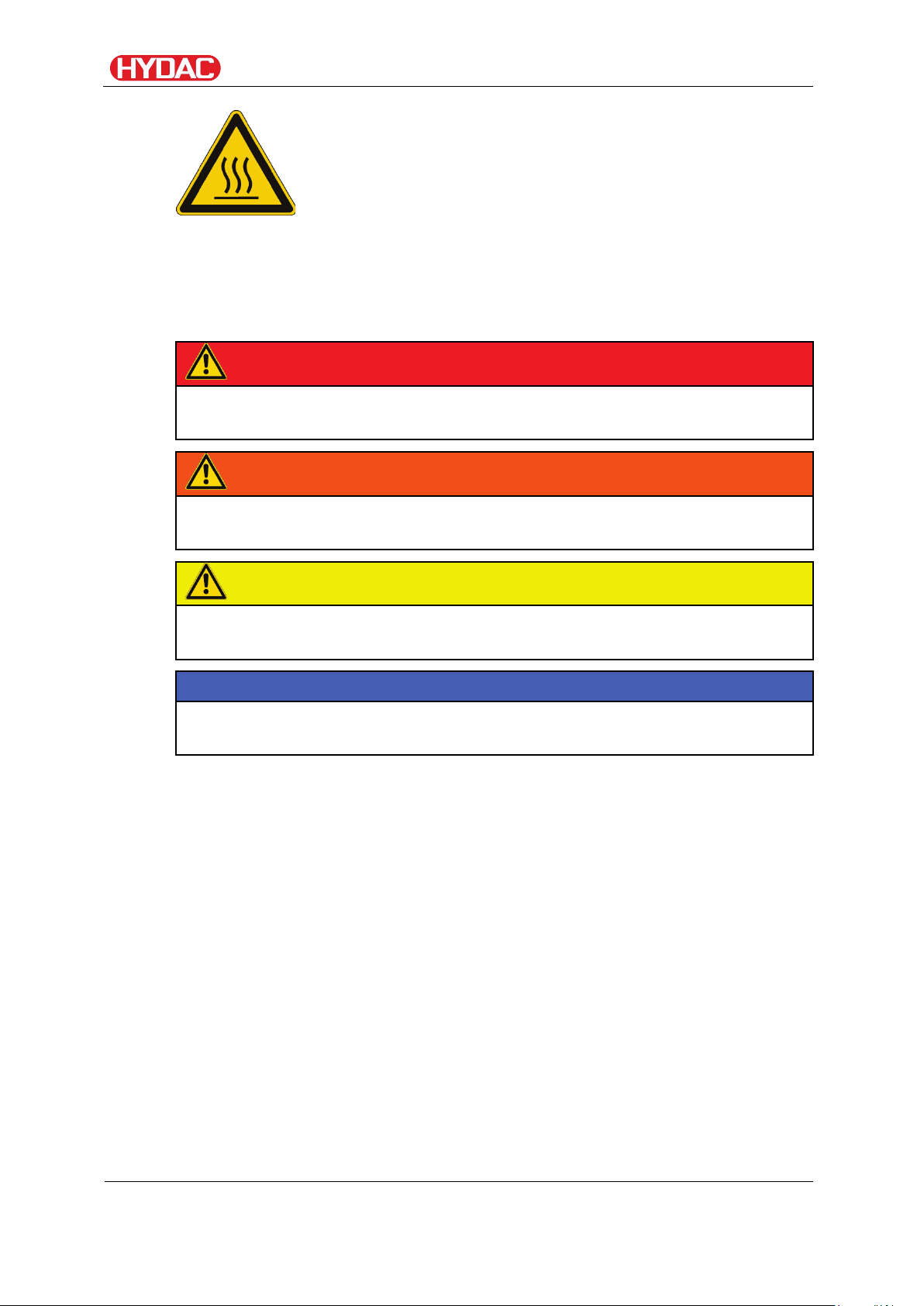
DANGER
DANGER – The signal word indicates a hazardous situation with a high level
of risk, which, if not avoided, will result lethal or serious injury.
WARNING
WARNING – The signal word indicates a hazardous situation with a medium
level of risk, which, if not avoided, can result lethal or serious injury.
CAUTION
CAUTION – The signal word indicates a hazardous situation with a low level
of risk, which, if not avoid
NOTICE
NOTICE – The signal word indicates a hazardous situation with a high level
of risk, which, if not avoided, will result in damage to property.
Risk of burns due to hot surfaces
Signal words and their meaning in the safety information and instructions
In these instructions you will find the following signal words:
ed, can result in minor or moderate injury.
FCU1310
BeWa FCU1310 V300 3371346f en-us 2017-01-27.docx 2017-01-27
en(us)
Page 11 / 124
Page 12
Safety information
Structure of the safety information and instructions
All warning instructions in this manual are highlighted with pictograms and
signal words. The pictogram and the signal word indicate the severity of the
danger.
Warning instructions listed before an activity are laid out as follows:
HAZARD SYMBOL
SIGNAL WORD
Type and source of danger
Consequence of the danger
► Measures to avert danger
Observe regulatory information
Observe the following regulatory information and guidelines:
• Legal and local regulations for accident prevention
• Legal and local regulations for environmental protection
• Country-specific regulations, organization-specific regulations
FCU1310
BeWa FCU1310 V300 3371346f en-us 2017-01-27.docx 2017-01-27
en(us)
Page 12 / 124
Page 13

Safety information
Proper/Designated Use
Claims for defects or liability, regardless of the legal foundation, do not apply
with incorrect or improper installation, commissioning, usage, handling,
storage, maintenance, repair, use of unsuitable components or other
circumstances for which HYDAC is not responsible.
HYDAC is not responsible for the installation, integration, selection of
interfaces to / into your system nor for the use or functionality of your system.
Use the product only for the application described below.
The FluidControl Unit FCU is a portable service unit for taking short-term
measurements of the solid particle contamination, temperature und %
saturation level in hydraulic systems.
Proper/designated use of the product extends to the following:
• Observing all the instructions contained in these operation and
maintenance instructions.
• Ensuring the execution of all inspection and maintenance work.
NOTICE
Impermissible operating conditions
The FCU will be destroyed
► Use the FCU with mineral oils or mineral oil-based raffinates whose
flash point is higher than 55°C / 131°F.
► Flush the FCU with low-viscosity mineral oils or mineral oil-based
raffinates (e.g. diesel) whose flash point is higher than 55°C / 131°F.
► Never flush the FCU with universal thinners or other degreasing fluids.
► Observe the permissible viscosity range (up to ISO VG 68):
10 - 350 mm²/s / 46 - 1622 SUS.
► Only operate the FCU in periodic intermittent duty (S3) with a relative
duty cycle of 40%
(S3 as per DIN EN 60034 / VDE 0530).
► Never use the FCU without a suction strainer.
FCU1310
BeWa FCU1310 V300 3371346f en-us 2017-01-27.docx 2017-01-27
en(us)
Page 13 / 124
Page 14
Safety information
which have a central
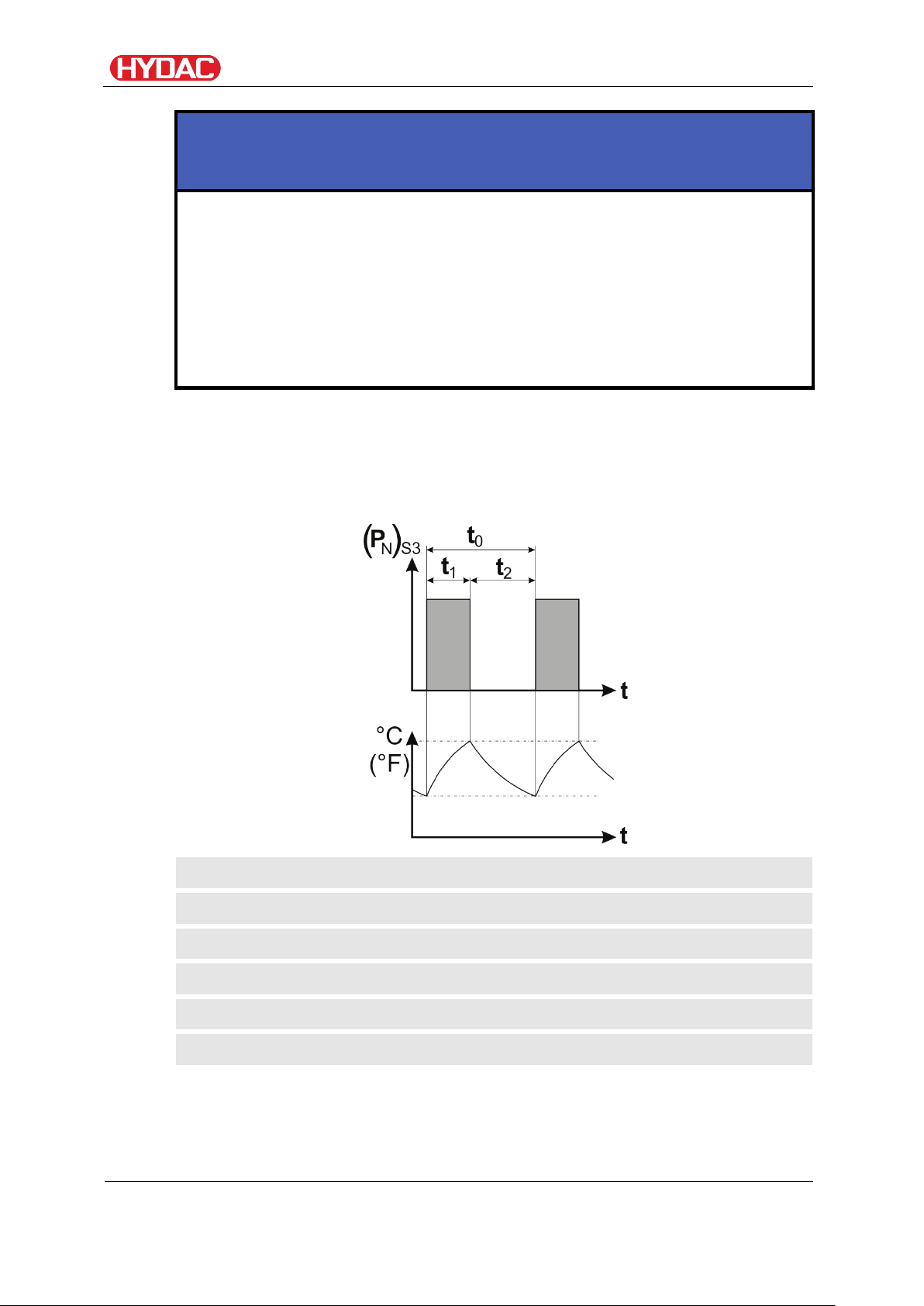
(PN)S3
=
Nominal power, operating mode S3
t = Time
t0 = Period (operation t1 + cooling phase t2)
t1 = Operation
t2 = Cooling phase (downtime)
°C (°F)
=
Temperature
NOTICE
Connection to 24 V DC on-board networks without load dump
The FCU will be destroyed.
► Use the FCU only on 24 V DC on-board networks
"Load Dump" fuse.
► Before connecting, be sure to check that a load dump is installed with
at least 30 V DC and is effective.
Periodic intermittent duty - operating mode S3, (as per DIN EN 60034-1 / DIN VDE 0530, part 1)
Operation t0 in time t1 at power (PN)S3 interchange periodically with the
cooling phases (downtimes) t2. The relative duty cycle is 40%.
FCU1310
BeWa FCU1310 V300 3371346f en-us 2017-01-27.docx 2017-01-27
en(us)
Page 14 / 124
Page 15
Safety information
Improper Use or Use Deviating from Intended Use
DANGER
Hazard due to use of the product other than
that intended
Bodily injury and damage to property will result
when operated improperly.
► Never operate the product in potentially
explosive atmospheres.
► Only use the product with permissible media.
Any use extending beyond this or deviating therefrom shall not be considered
intended use. HYDAC FILTER SYSTEMS GmbH will assume no liability for
any damage resulting from such use. The user alone, shall assume any and
all associated risk.
Improper use may result in hazards and/or will damage the product.
Examples of improper use:
• Operation with fluid that has a flash point under 55°C / 131°F.
• Flush with universal thinners or other degreasing fluids
• Operation in potentially explosive atmospheres.
• Operation under non-approved operational conditions.
• Modifications to the product made by the user or purchaser.
• Continuous monitoring of the fluid cleanliness (continuous operation)
• Improper connection of the pressure and return flow hoses.
• Operation at a measurement point with impermissible pressure.
• Operation on 24 V DC on-board networks without central
"Load Dump" fuse.
• Operation with an impermissible fluid.
• Operation with faulty or damaged hoses.
• Operation with damaged connector cable.
FCU1310
BeWa FCU1310 V300 3371346f en-us 2017-01-27.docx 2017-01-27
en(us)
Page 15 / 124
Page 16

Safety information
Activity
Person
Knowledge
Transport / storage
Auxiliary
• No specialist knowledge
Startup operation
Auxiliary
• Product-specific knowledge
Troubleshooting,
Specialist
• Safe handling/use of tools
Disassembly
Service staff
• Very detailed product-specific
Disposal
Specialist
• Proper and environmentally-
Qualifications of personnel / target group
Auxiliary, operational and specialist personnel must have read and
understood the operating instructions, in particular the safety information and
instructions, and applicable regulations before beginning work.
The operating instructions and applicable regulations are to kept so they are
accessible for operating and specialist personnel.
These operating instructions are intended for:
Auxiliary personnel: such persons have been instructed about the product
and informed about potential hazards that can result from improper use.
Operating personnel: such persons have been instructed in product
operation and are aware of potential dangers due to improper use.
Specialist personnel: such persons with corresponding specialist training
and several years' work experience. They are able to assess and perform the
work assigned to them, they are also able to recognize potential hazards.
Operations control
Maintenance,
Decommissioning,
personnel
personnel
personnel
(only with
authorized
HYDAC
Service)
personnel
required
• Knowledge about how to
handle operating media.
• Product-specific knowledge
knowledge
friendly disposal of materials
and substances
• Decontamination of
contaminants
FCU1310
BeWa FCU1310 V300 3371346f en-us 2017-01-27.docx 2017-01-27
en(us)
• Knowledge about reuse
Page 16 / 124
Page 17

Safety information
Wear personal protection equipment
Observe the information relating to personal protection equipment in the
safety data sheet of the operations fluid.
• Wear eye protection.
• Wear gloves.
Stoppage in an emergency (EMERGENCY STOP)
In the event of an emergency, disconnect the FCU from the power supply
and from the hydraulic system.
FCU1310
BeWa FCU1310 V300 3371346f en-us 2017-01-27.docx 2017-01-27
en(us)
Page 17 / 124
Page 18
FCUOpening/Closing
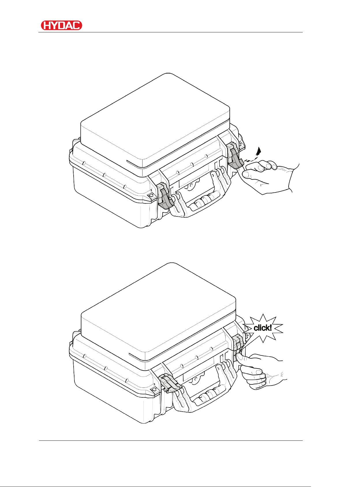
FCUOpening/Closing
Open the FCU by releasing both clips.
Close the FCU using both clips. Make sure that these audibly snap into
place.
FCU1310
BeWa FCU1310 V300 3371346f en-us 2017-01-27.docx 2017-01-27
en(us)
Page 18 / 124
Page 19
FCUtransporting
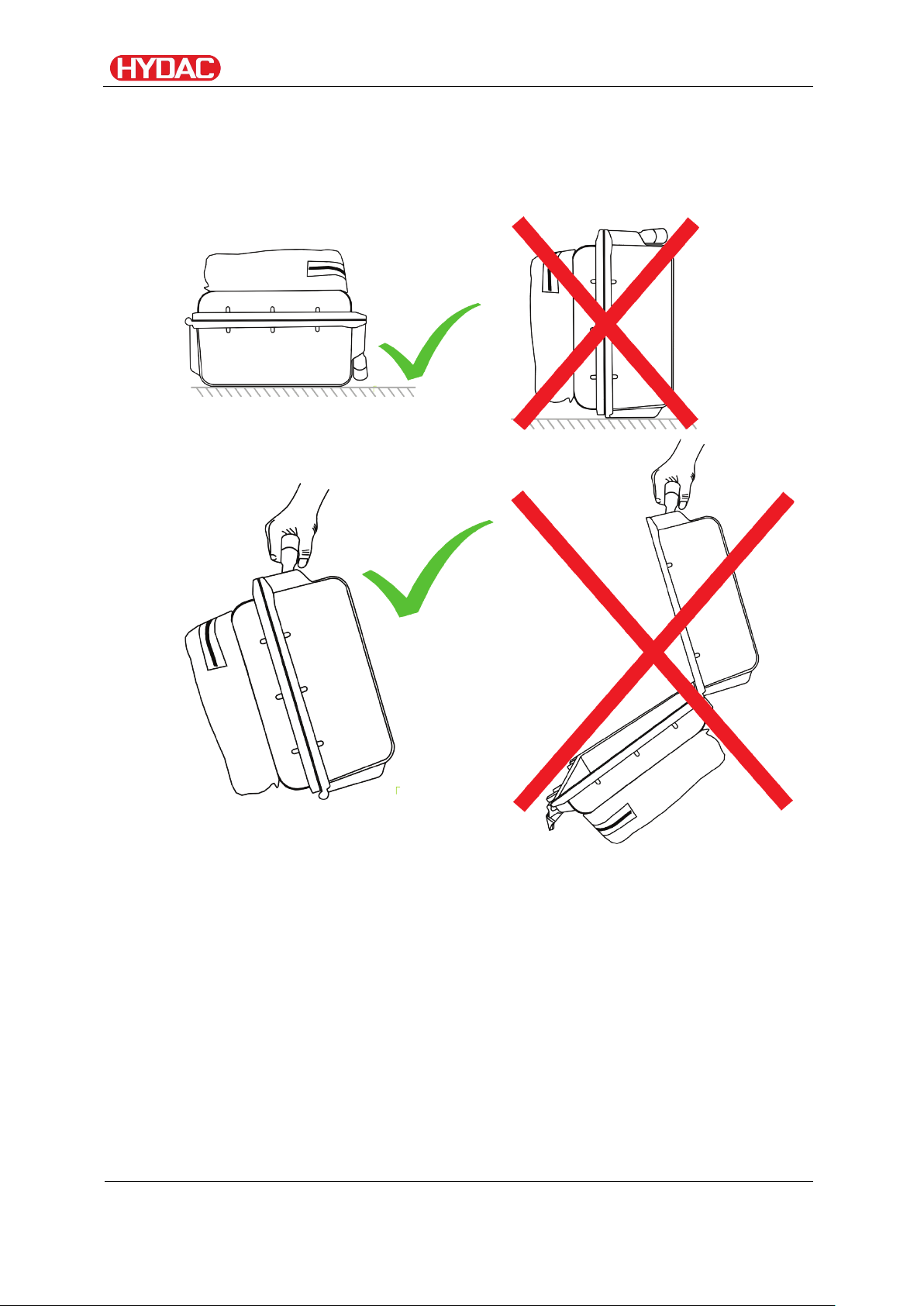
FCUtransporting
Transport the FCU only when it is in closed position; carry it flat or by the
handle.
FCU1310
BeWa FCU1310 V300 3371346f en-us 2017-01-27.docx 2017-01-27
en(us)
Page 19 / 124
Page 20
FCUstoring
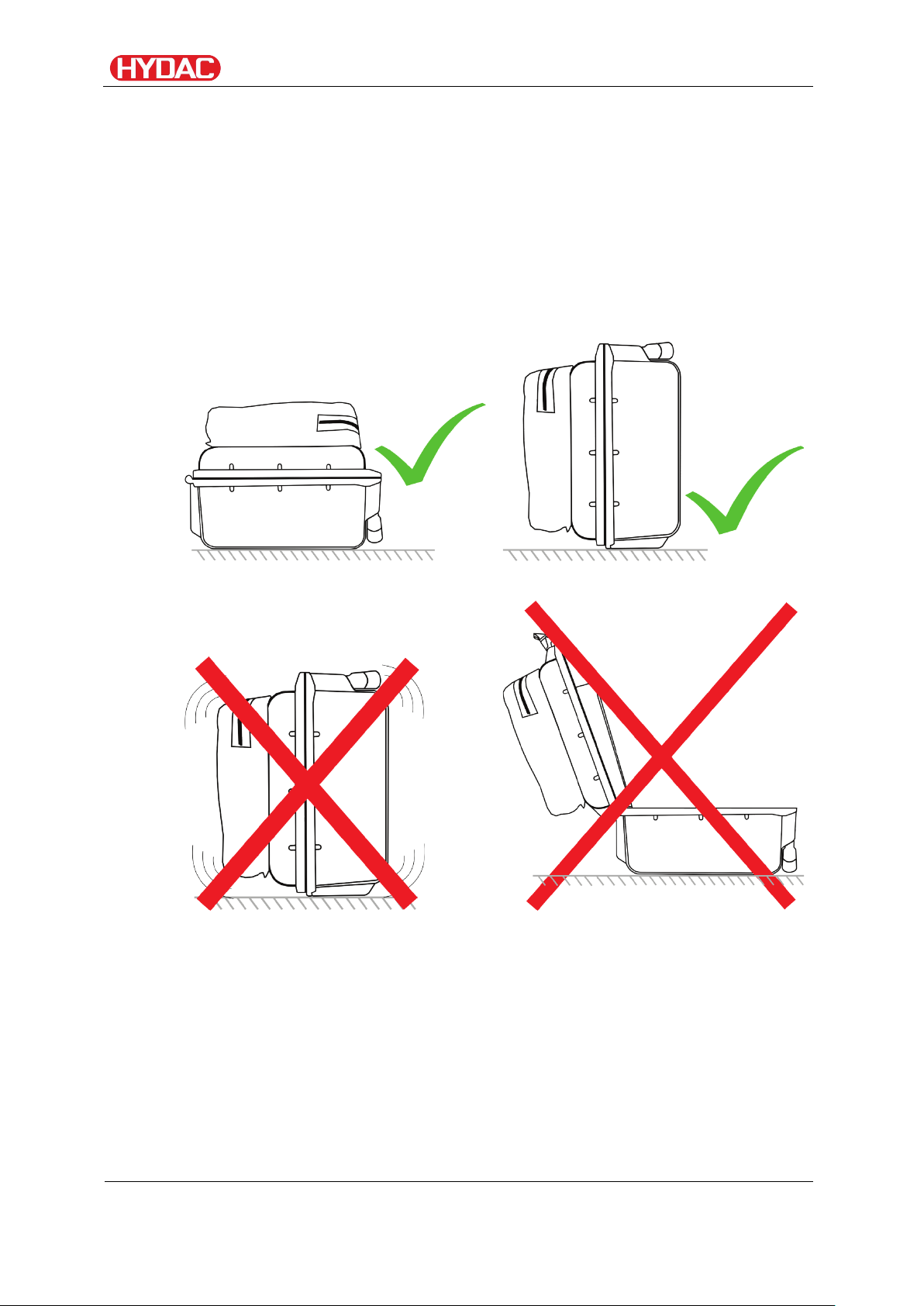
FCUstoring
Drain and rinse the FCU completely before putting it into storage. See page
88 in the "FCU flushing" chapter for details on rinsing the FCU.
Observe permissible conditions required for storage on page 108 in the
"Technical Data" chapter.
Store the FCU closed and in a horizontal position in a dry, clean place. If
stored in a vertical position, the FCU must not be exposed to any shaking or
vibration.
FCU1310
BeWa FCU1310 V300 3371346f en-us 2017-01-27.docx 2017-01-27
en(us)
Page 20 / 124
Page 21
Decoding the model code label
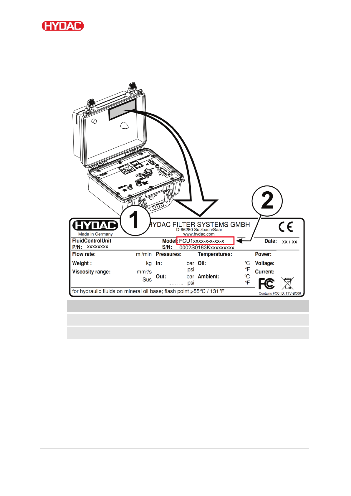
Item
->
Description
(1)
->
Type label for FCU
(2)
->
Model code; for details, see page 110.
Decoding the model code label
For identification details of the FluidControl Unit, see the model code label.
The type label displays the product ID and important technical data.
FCU1310
BeWa FCU1310 V300 3371346f en-us 2017-01-27.docx 2017-01-27
en(us)
Page 21 / 124
Page 22

Decoding the model code label
Row
->
Description
Model
->
Model code; for details, see page 110.
Date
->
Production year/week
P/N
->
Part number
S/N
->
Serial no.
Flow rate
->
Flow rate
Weight
->
Weight when empty
Viskosity range
->
Permissible viscosity range
Pressures
->
Pressure specifications
In
->
Permissible pressure at port INLET
Out
->
Permissible pressure at port OUTLET
Temperatures
->
Temperature specifications
Oil
->
Permissible oil temperature range
Ambient
->
Permitted ambient temperature range
Power
->
Power consumption
Voltage
->
Voltage
Current
->
Current consumption
The following information can be found on the name plate of the product:
FCU1310
BeWa FCU1310 V300 3371346f en-us 2017-01-27.docx 2017-01-27
en(us)
Page 22 / 124
Page 23
Checking the scope of delivery
Item
Qty
Description
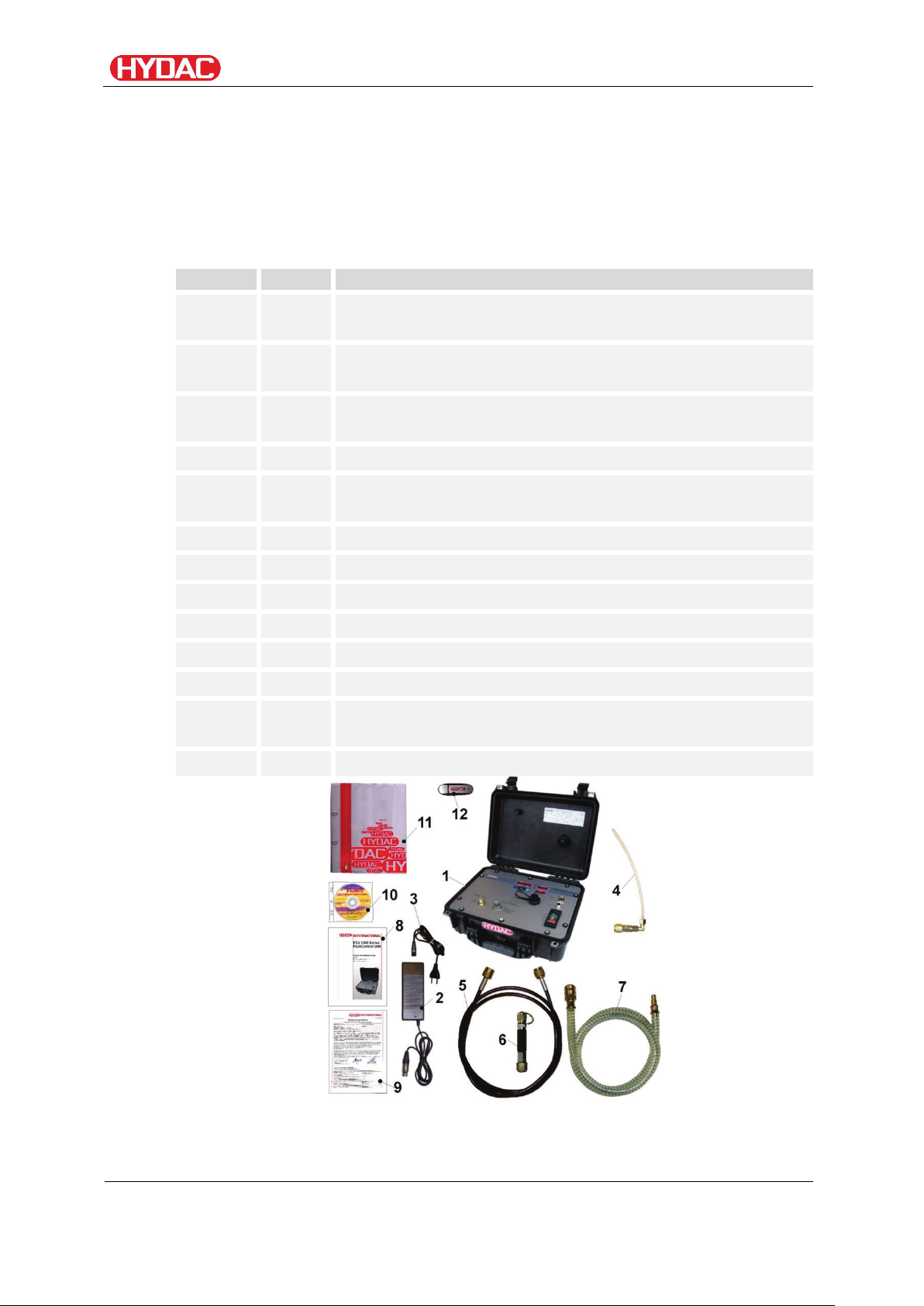
1
1
FluidControl Unit FCU, including attachable bag for
cables and hoses
2
1
Power supply, primary: 90-240 V AC / secondary:
24 V DC / 5 A
3
4
Connection cable for power adapter (Europe,
USA/Canada, UK, Australia, Japan)
4
1
Suction hose, open end, clear-transparent, L = 0.3 m
5
1
High pressure hose with screwed joint, type 1620, color:
black, L = 2 m
6
1
High-pressure adapter
7
1
Return hose, transparent, L = 2 m
8
1
Operating and maintenance instructions
9
1
Calibration certificate
10
1
CD-ROM with FluMoS software
11
1
Pocket for documents
12
1
USB memory stick with operating and maintenance
instructions (PDF file) in additional languages
-
1
Quick start manual
Checking the scope of delivery
The FluidControl Unit comes factory-assembled. Before commissioning the
FCU, check the contents of the consignment to make sure everything is
present.
The following items are supplied:
A USB bluetooth adapter for the PC is a free gift and is not part of the
delivery.
FCU1310
BeWa FCU1310 V300 3371346f en-us 2017-01-27.docx 2017-01-27
en(us)
Page 23 / 124
Page 24

What can the product do?
What can the product do?
The FluidControl Unit FCU is a portable service unit for taking short-term
measurements of the solid particle contamination, temperature und %
saturation level in hydraulic systems.
Knowledge on the level and amount of contamination allows you to check
and document quality standards and introduce the required optimization
measures.
The integrated pump and the hoses supplied enable usage with:
• Control circuits
• Pressure circuits
• Depressurised containers
The internal data memory enables measurements to be recorded together
with a time-stamp.
The USB interface can be used to copy all measurements to a USB memory
stick or to send them to a mobile device via Bluetooth where they can be
analyzed using MS Excel or the Fluid Monitoring software FluMoS.
Additional features include:
• Optical measurement of the degree of solid particle contamination
• Capacitive recording of the water saturation in %
• Resistive measurement of the temperature
• Suitable for hydraulic fluids (up to ISO VG 68)
10 - 350 mm²/s / 16 - 1622 Sus
• Automatic measurement and display of cleanliness ratings in
accordance with:
• ISO 4406:1987; NAS 1638
• ISO 4406:1999; SAE AS 4059 (D)
• Measurement accuracy +/- ½ ISO code in the calibrated range
• Supply voltage of 24 V DC / 4 A for operation on mobile machine on-
board networks
• Network adapter 90 - 240 V AC / 24 V DC 5 A included in the scope of
delivery
• Operating pressure without high-pressure adapter max. 45 bar / max.
650 psi,
Operating pressure with high-pressure adapter max. 345 bar / max.
5000 psi
• Integrated pump for the automatic control of oil flow
FCU1310
BeWa FCU1310 V300 3371346f en-us 2017-01-27.docx 2017-01-27
en(us)
Page 24 / 124
Page 25
What can the product do?
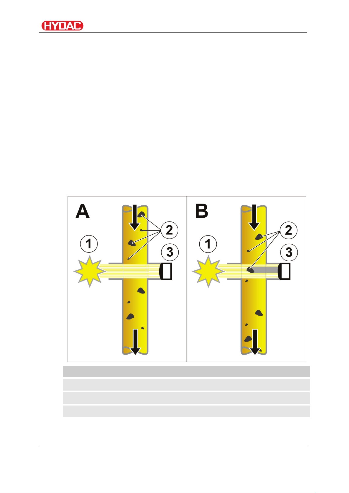
Item
Designation
1
Light source
2
Particle
3
Photo detector
Counting contaminant particles
The measuring principle of the light blockade procedure is shown in
simplified form in the following sketch.
The light source transmits monochromatic light through the flow of oil to a
photo detector, which produces a particular electrical signal. If a particle gets
between the light source and the photo detector, then a shadow will be cast
on the photo detector.
This shadow causes a change in the electrical signal generated by the photo
detector. This change makes it possible to determine the size of the shadow
cast by the particle and thus to gauge the size of the particle itself.
This procedure makes it possible to determine the cleanliness class
according to ISO 4406:1987, ISO 4406:1999, NAS 1638 and SAE AS 4059.
The disruption factors of this measurement principle are foreign fluids and
small gas bubbles that lead to refractions, thus causing them to be counted
as particles as well.
FCU1310
BeWa FCU1310 V300 3371346f en-us 2017-01-27.docx 2017-01-27
en(us)
Page 25 / 124
Page 26
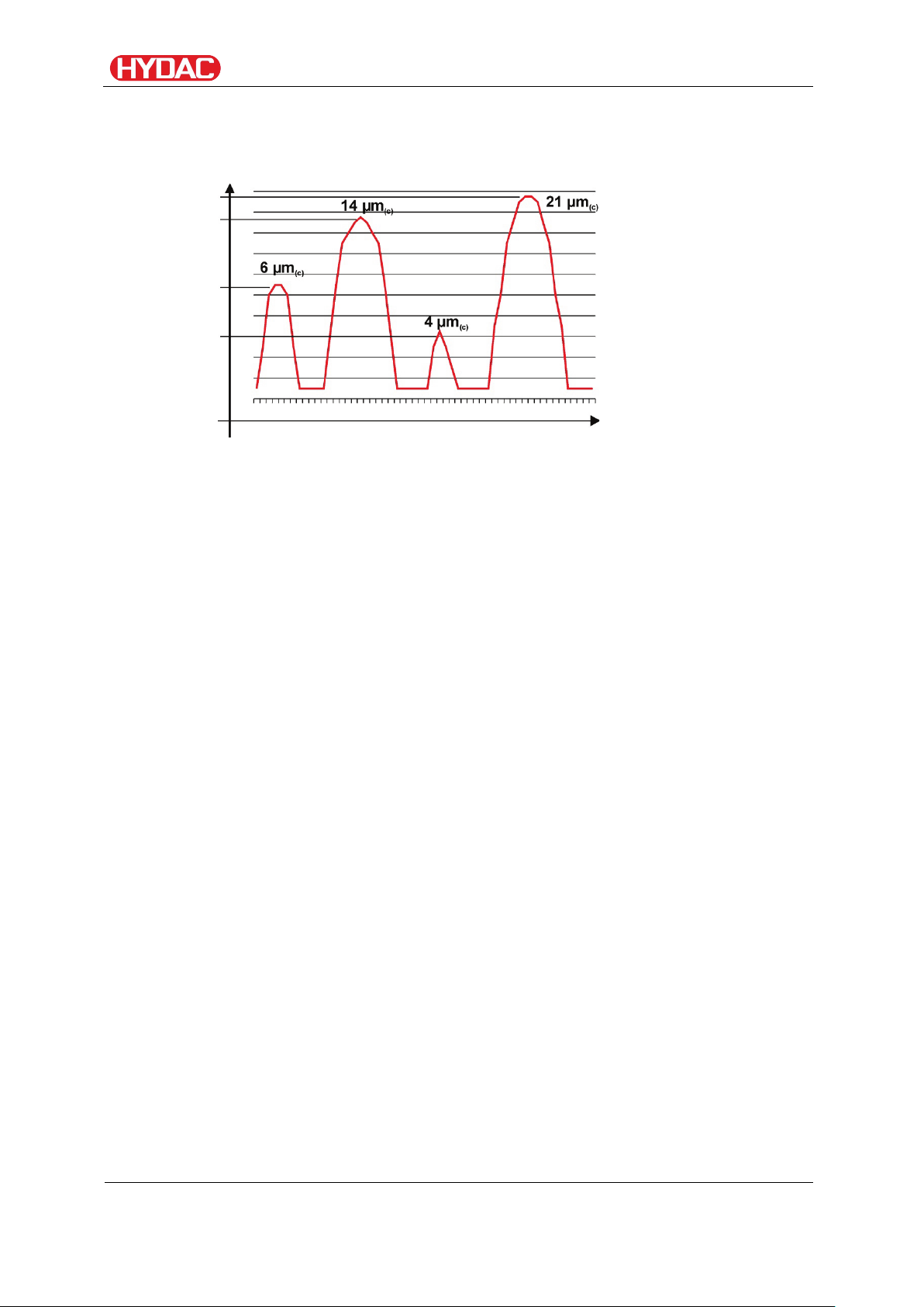
What can the product do?
Each of the signal peaks corresponds to the shadow cast by one particle.
The signal height or amplitude reflects the particle size. Thresholds are used
to classify the particle sizes >2, >5, >15, >25 µm or >4, >6, >14, >21 µm
(c)
.
Threshold values
Time
FCU1310
BeWa FCU1310 V300 3371346f en-us 2017-01-27.docx 2017-01-27
en(us)
Page 26 / 124
Page 27
What can the product do?
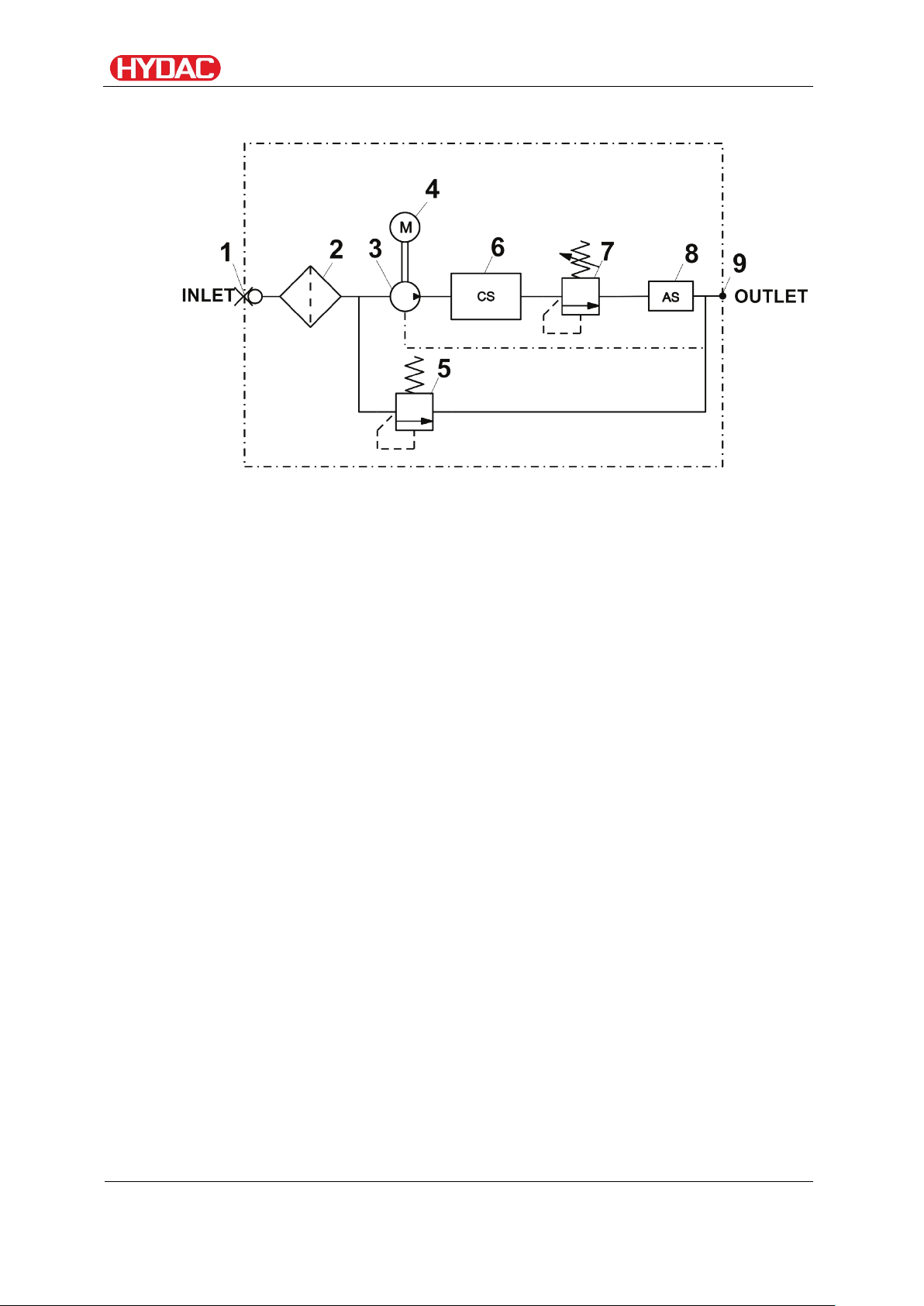
How the product works
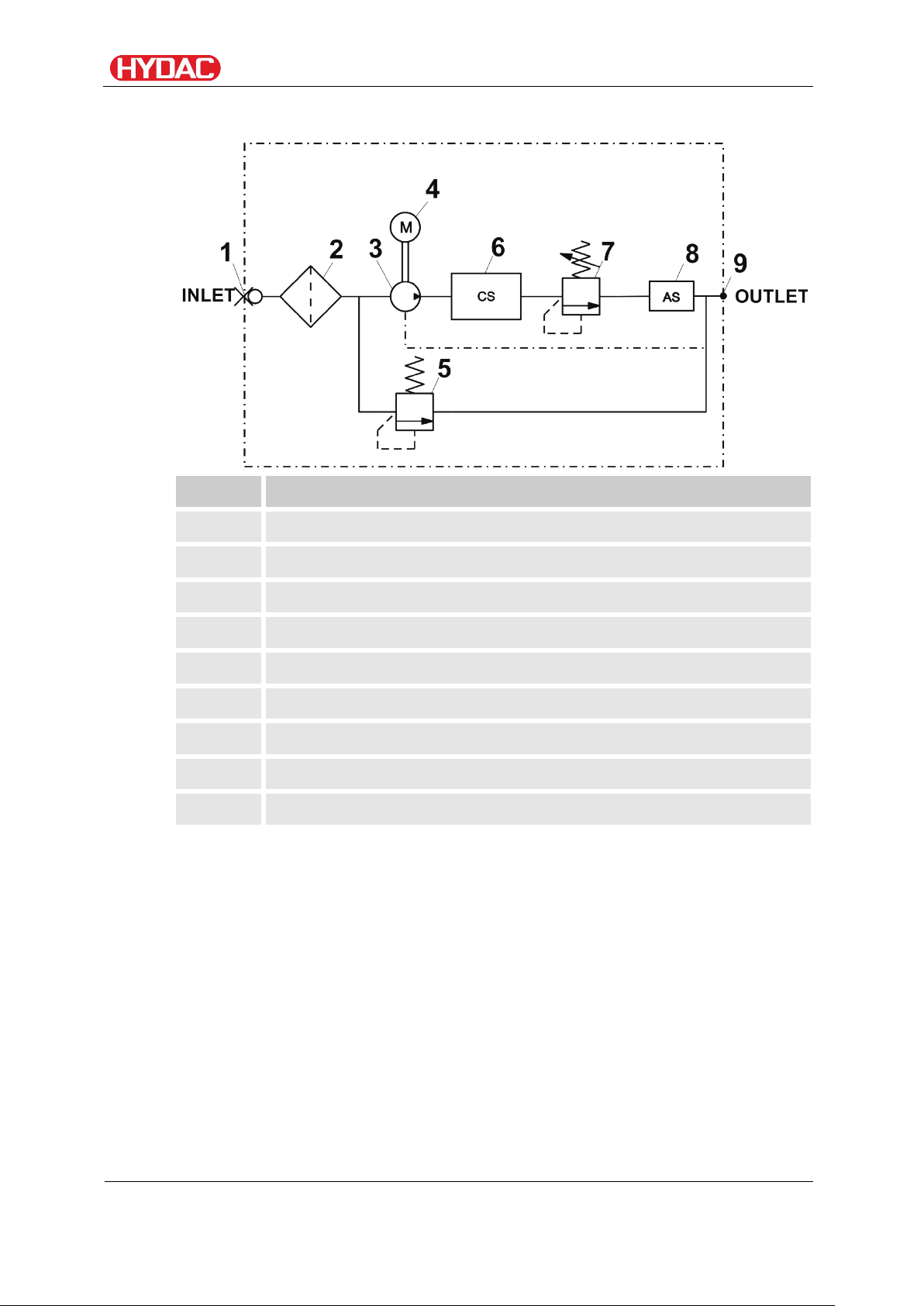
From the oil source (either a pressure port or a bottle sample), a continuous
oil flow is established through the port (1) INLET by an electrically controlled
gear pump (3).
A suction strainer (2) protects the pump from coarse contamination.
The oil current to be analyzed flows through an optical ContaminationSensor
(6). The contaminant particles contained in the oil current cause the light
beam to be darkened in a pulse-like manner. An electronic evaluation module
classifies and counts these measurement signals according to particle
diameter. The evaluation module continuously computes the cleanliness
classes for the reference volume of 100°ml based on the measurement
signals of the optical sensor.
A defined pressure is generated in the oil flow via a counter balance valve
(7). This serves to minimize air bubbles in the system, which could skew the
measurement results.
The pressure relief valve (5) protects the pump and the measuring cell from
excessive pressure.
The oil flow leaves the port (9) OUTLET and is routed by the return hose to a
pressurized tank.
The electronic evaluation module monitors:
• the function of the ContaminationSensors
• the oil flow
• the power supply voltage
• the function of the AquaSensors
When a malfunction occurs, an error message automatically appears in the
display and interrupts the measurement. The evaluation module will
recognize when the cause of error has been corrected, and the unit will reset
automatically and resume the measurement operation.
FCU1310
BeWa FCU1310 V300 3371346f en-us 2017-01-27.docx 2017-01-27
en(us)
Page 27 / 124
Page 28
What can the product do?
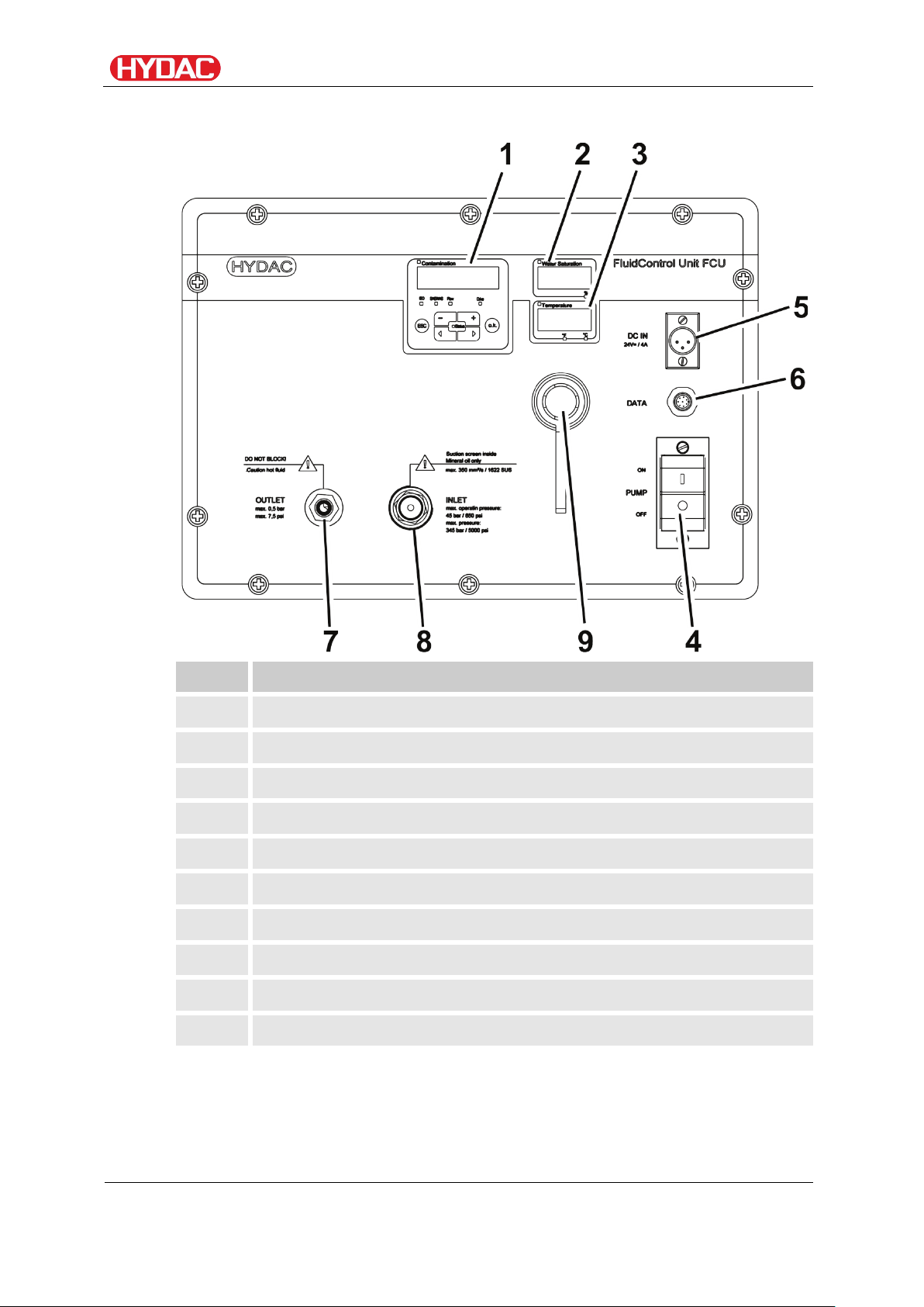
Item
Designation
1
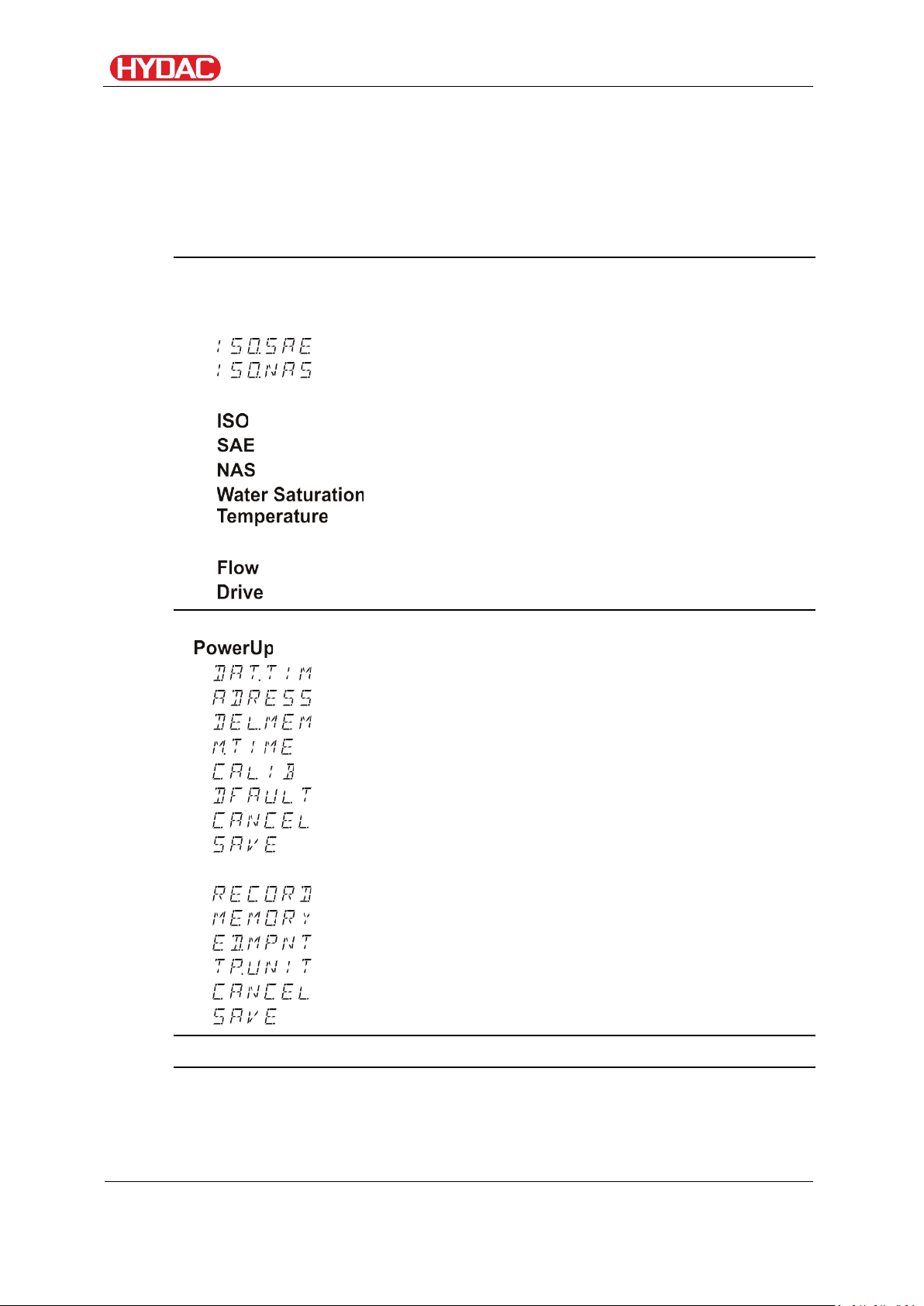
Display of “ISO, SAE/NAS, Flow, Drive” with keypad
2
Display of the percentage "water saturation"
3
"Fluid temperature" display
4
ON / OFF switch for the internal pump
5
Supply voltage 24 V DC
6
Data interface (DATA)
7
Connection OUTLET
8
Connection INLET, type 1604
9
USB interface with cover
-
Bluetooth interface
Overview of control panel/operating elements
FCU1310
BeWa FCU1310 V300 3371346f en-us 2017-01-27.docx 2017-01-27
en(us)
Page 28 / 124
Page 29
What can the product do?
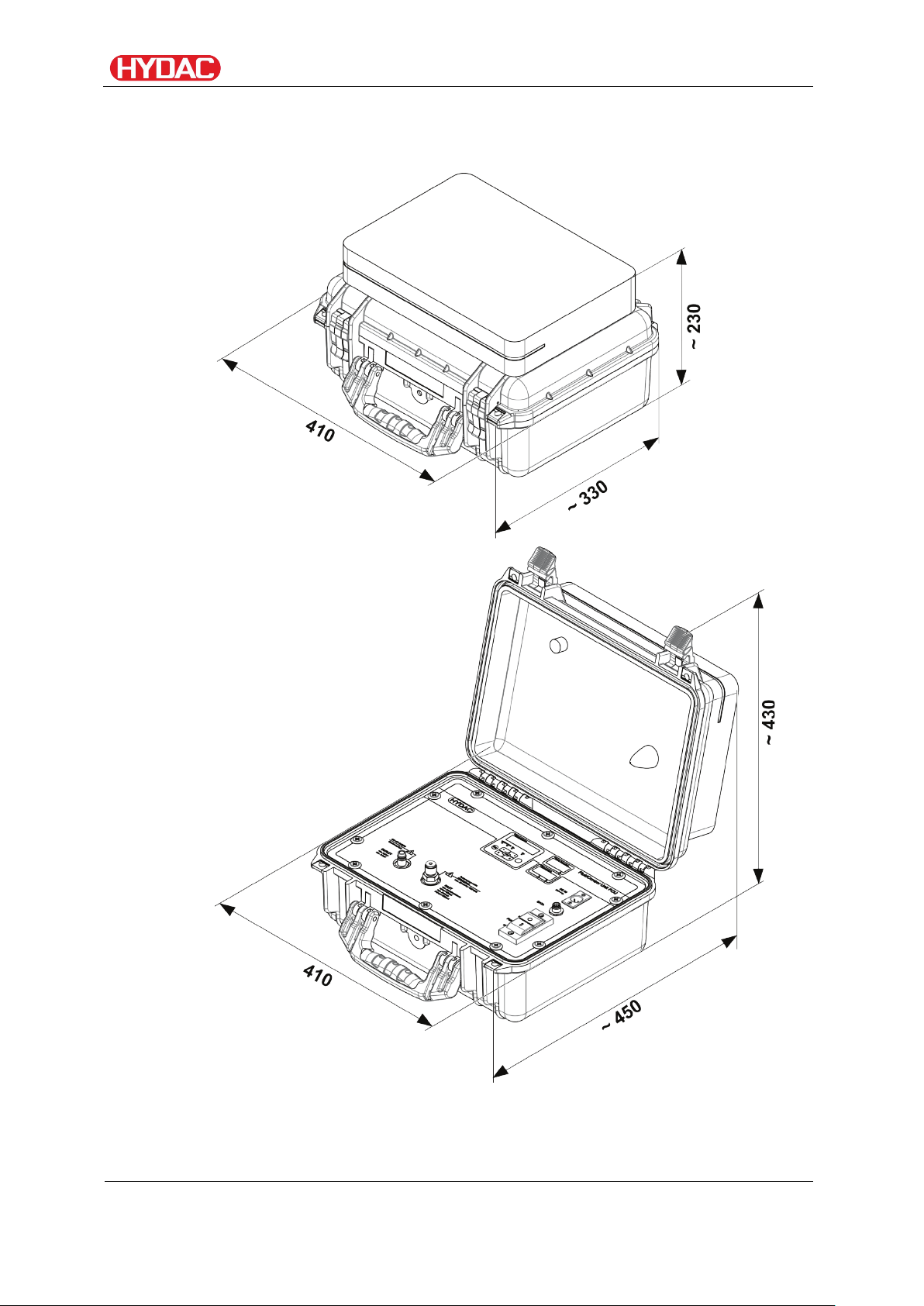
Dimensions
The FCU has the following dimensions.
All dimensions in mm.
FCU1310
BeWa FCU1310 V300 3371346f en-us 2017-01-27.docx 2017-01-27
en(us)
Page 29 / 124
Page 30
What can the product do?
Hydraulic diagram
Item Designation
1 INLET, gauge port type 1604
2 Suction screen, 400 µm
3 Gear pump
4 Electric motor
5 Pressure relief valve
6 ContaminationSensor unit
7 Counter balance valve
8 AquaSensor AS1000
9 OUTLET, DN7 Quick coupling nipple
FCU1310
BeWa FCU1310 V300 3371346f en-us 2017-01-27.docx 2017-01-27
en(us)
Page 30 / 124
Page 31

Using the BatteryPack (accessory)
With the locking pin (2), the
Using the BatteryPack (accessory)
With the BatteryPack, which is available as an accessory, you can make the
FCU independent of the electrical supply network.
For technical details on the BatteryPack, see its instruction brochure.
BatteryPack (1) is held securely in the
mounting rails (3) during transport.
For operation with the BatteryPack, fit the connector into the socket labeled
DC IN of the FCU.
FCU1310
BeWa FCU1310 V300 3371346f en-us 2017-01-27.docx 2017-01-27
en(us)
Page 31 / 124
Page 32

Using the BatteryPack (accessory)
1.
Remove the connector (A) from the
2.
Slide the BatteryPack into the
To fit the BatteryPack into its holder, proceed as follows:
socket on the BatteryPack.
mounting rails from above.
FCU1310
BeWa FCU1310 V300 3371346f en-us 2017-01-27.docx 2017-01-27
en(us)
Page 32 / 124
Page 33

Using the BatteryPack (accessory)
3.
Pull the locking pin (1).
4.
Insert the connector into the socket
Slide the BatteryPack down until it
touches the lower stop in the guide
rails (2).
Release the locking pin (3). A spring
will return the locking pin to its
original position, thus securing the
BatteryPack.
Check that the BatteryPack is firmly
seated.
on the BatteryPack.
FCU1310
BeWa FCU1310 V300 3371346f en-us 2017-01-27.docx 2017-01-27
en(us)
Page 33 / 124
Page 34

Using the BatteryPack (accessory)
1.
Remove the connector from the
2.
Pull the locking pin out to release the
To remove it, proceed as follows:
socket.
BatteryPack (1).
Slide the BatteryPack upwards (2).
FCU1310
BeWa FCU1310 V300 3371346f en-us 2017-01-27.docx 2017-01-27
en(us)
Page 34 / 124
Page 35

Using the BatteryPack (accessory)
3.
Pull the BatteryPack up and out of
the mounting rails.
Then insert the connector back into
the socket on the BatteryPack.
FCU1310
BeWa FCU1310 V300 3371346f en-us 2017-01-27.docx 2017-01-27
en(us)
Page 35 / 124
Page 36

Preparing the FCU for measurement
1.
After the unit is plugged in, HYDAC FCU 1### appears in moving
2.
The internal sensors will then be checked.
3.
The self-test with countdown follows in the display
3.
The FCU is now ready.
4.
As long as the pump is not running and no fluid is being pumped, the
To insert the connector
To remove the connector
Insert the connector into the socket
Press the catch (1) on the connector
Preparing the FCU for measurement
Before operation, the FCU must first be hydraulically and electrically
connected, as described below.
Connecting/Disconnecting the FCU electrically
The FCU has a 3-way plug to connect to a 24 V DC supply. Insert the 3-pin
jack plugs of the adapter (included in the FCU delivery). Connect the power
plug of the adaptor into the power supply.
letters, followed by the firmware version, which appears for 2 seconds.
The display will show as well as the sensor firmware.
status LED will flash red, and the display will show .
This means that there is no oil flow.
until it audibly snaps in ( ).
and then pull (2) the connector out.
FCU1310
BeWa FCU1310 V300 3371346f en-us 2017-01-27.docx 2017-01-27
en(us)
Page 36 / 124
Page 37

Preparing the FCU for measurement
Plug in return hose
Detach return hose
Plug in/Detach return hose
Closed or blocked outlet at the connection OUTLET
The FCU can be damaged.
► Never seal the OUTLET connection OUTLET.
► Put the free end of the OUTLET return hose into an unpressurized
container.
NOTICE
Fit the quick-action coupling on the return hose to the nipple. Make sure that
the coupling audibly snaps into place ( ). Make sure that the quick-action
coupling is firmly seated.
Put the other end of the return hose into a depressurized container or tank.
FCU1310
BeWa FCU1310 V300 3371346f en-us 2017-01-27.docx 2017-01-27
en(us)
Page 37 / 124
Page 38

Preparing the FCU for measurement
Select the measurement location so that the sample measured comes
If the FCU is installed near the measurement point, avoid delayed
While installing the inlet hose INLET, make sure that no siphon results.
Selecting the measurement location
from a turbulent location, with a good flow. For example on a pipe
bend. This ensures that a typical sample is analyzed.
measurement results and sedimentation (particle deposits in the line).
FCU1310
BeWa FCU1310 V300 3371346f en-us 2017-01-27.docx 2017-01-27
en(us)
Page 38 / 124
Page 39

Preparing the FCU for measurement
Pressure at the
Measurement method
Details
0 bar /
Measuring from unpressurized containers
47
1 - 45 bar /
Measuring up to max. 45 bar / 650 psi
40
15 - 345 bar /
Measuring in the range 5 to 345 bar /
43
Select the measurement method according to the pressure involved
After you have selected the measurement location according to the abovementioned criteria, determine what the operating pressure is at that location.
Select the measurement method that is suitable for the pressure at the
measurement point:
measurement
point
0 psi
14 - 650 psi
217 - 5000 psi
are on
page
217 to 5000 psi
FCU1310
BeWa FCU1310 V300 3371346f en-us 2017-01-27.docx 2017-01-27
en(us)
Page 39 / 124
Page 40

Preparing the FCU for measurement
Measuring up to max. 45 bar / 650 psi
WARNING
Hydraulic systems are under pressure
Danger of bodily injury
► The system must be depressurized before
performing any work on the product.
► If the pressurized connection is connected to
the hydraulic system, oil will flow through the
FCU.
► Make sure that the specified sequence is
followed.
NOTICE
If the operating pressure exceeds 45 bar / 650 psi
The excess pressure will be discharged via port OUTLET
► Never seal the connection OUTLET.
► Put the free end of the OUTLET return hose into an unpressurized
container.
► When operating, always observe the permissible operating pressure.
The FCU can withstand pressures up to 345 bar / 5000 psi.
FCU1310
BeWa FCU1310 V300 3371346f en-us 2017-01-27.docx 2017-01-27
en(us)
Page 40 / 124
Page 41

Preparing the FCU for measurement
-
Return hose
-
High-pressure hose
1.
Go through the steps in chapter
2.
Check the pressure at the
measurement location. The pressure
Required hoses:
Make sure that the following sequence is observed:
"FCU für die Messung vorbereiten“
on pages 36 to 39.
there must be in the range of
1 to 45 bar / 14 to 650 psi.
If the pressure exceeds
45 bar / 650 psi, use the highpressure adapter (see page 43).
FCU1310
BeWa FCU1310 V300 3371346f en-us 2017-01-27.docx 2017-01-27
en(us)
Page 41 / 124
Page 42

Preparing the FCU for measurement
3.
Connect the inlet pressure hose
4.
Connect the other end of the INLET
5.
Switch on the internal pump.
6.
This completes the hydraulic
7.
The FCU will start with the
(black) to the port INLET of the FCU
(1).
Screw the measurement coupling
clockwise (2) onto the connection
and screw it finger tight.
pressure hose to the measurement
point of the system.
installation.
measurement.
FCU1310
BeWa FCU1310 V300 3371346f en-us 2017-01-27.docx 2017-01-27
en(us)
Page 42 / 124
Page 43

Preparing the FCU for measurement
Measuring in the range 5 to 345 bar / 217 to 5000 psi
WARNING
Hydraulic systems are under pressure
Danger of bodily injury
► The system must be depressurized before
performing any work on the product.
► If the pressurized connection is connected to
the hydraulic system, oil will flow through the
FCU.
► Make sure that the specified sequence is
followed.
NOTICE
If the operating pressure exceeds 345 bar / 5000 psi
The excess pressure will be discharged via port OUTLET
► Never seal the connection OUTLET.
► Put the free end of the OUTLET return hose into an unpressurized
container.
► When operating, always observe the permissible operating pressure.
The FCU can withstand pressures up to 345 bar / 5000 psi.
FCU1310
BeWa FCU1310 V300 3371346f en-us 2017-01-27.docx 2017-01-27
en(us)
Page 43 / 124
Page 44

Preparing the FCU for measurement
-
Return hose
-
High-pressure adapter
-
High-pressure hose
1.
Go through the steps in chapter
Required hoses / adapters:
Make sure that the following sequence is observed:
"Preparing the FCU for
measurement“ on pages 36 to 39.
FCU1310
BeWa FCU1310 V300 3371346f en-us 2017-01-27.docx 2017-01-27
en(us)
Page 44 / 124
Page 45

Preparing the FCU for measurement
2.
Check the pressure at the
measurement location. The pressure
3.
Screw the high-pressure adapter
4.
Connect the high pressure hose to
5.
Connect the other end of the high
there must be in the range from 15 345 bar / 217 - 5000 psi.
If the pressure is greater
than 345 bar / 5000 psi, please
cancel the process. Look for a
different measurement point.
onto the INLET connection of the
FCU
the high pressure adaptor.
pressure hose to the measurement
point of the hydraulic system.
FCU1310
BeWa FCU1310 V300 3371346f en-us 2017-01-27.docx 2017-01-27
en(us)
Page 45 / 124
Page 46

Preparing the FCU for measurement
6.
Switch on the internal pump.
7.
This completes the hydraulic
8.
The FCU will start with the
installation.
measurement.
FCU1310
BeWa FCU1310 V300 3371346f en-us 2017-01-27.docx 2017-01-27
en(us)
Page 46 / 124
Page 47

Preparing the FCU for measurement
-
Return hose
-
Suction hose
To guarantee valid and direct measurements, prime the FCU. To do
Measuring from unpressurized containers
Required hoses:
this, draw in ≈ 120 ml fluid via the inlet hose in order to completely
fill the hydraulic circuit and the inlet hose.
If the FCU is not primed, an air-oil mixture at the start of
measurement will flow through the FCU. The sensor will interpret
this air-oil mixture as particulate soiling and will thus falsify the
measurement result.
For an initial test without priming the FCU and hoses, you need at
least 300 ml of fluid.
FCU1310
BeWa FCU1310 V300 3371346f en-us 2017-01-27.docx 2017-01-27
en(us)
Page 47 / 124
Page 48

Preparing the FCU for measurement
1.
Go through the steps in chapter
2.
Connect the suction hose
3.
This completes the hydraulic
4.
Switch on the internal pump.
5.
The FCU will start with the
Make sure that the following sequence is observed:
"Preparing the FCU for
measurement“ on pages 36 to 39.
(transparent) to the INLET of the
FCU.
Put the other end of the transparent
suction hose into an unpressurized
container.
installation.
measurement.
FCU1310
BeWa FCU1310 V300 3371346f en-us 2017-01-27.docx 2017-01-27
en(us)
Page 48 / 124
Page 49

FCUoperating
Item
LED
Designation
A
STATUS
Status display
B
Display
Consists of a 6-digit display and shows the
C
Measured
Indicates the displayed variable of the display
D
Service variable
Indicates the service variable of the display
E
Unit
The units for the fluid temperature display
FCUoperating
When the FCU is powered up, it is ready for use and the parameters can be
set.
In the following, the individual controls and their use are described.
Display and keypad elements
(see page 99 for details).
selected measured values.
variable
value, e.g.: .
value, i.e.: .
.
FCU1310
BeWa FCU1310 V300 3371346f en-us 2017-01-27.docx 2017-01-27
en(us)
Page 49 / 124
Page 50

FCUoperating
Keyboard
Description
- one level down
(top level)
- Change values at the lowest levels
- Scroll through display
The keyboard consists of six buttons. These buttons are used to operate the
FCU and to navigate through the menus (hierarchically structured).
- confirm changed value (lowest level)
- confirm when changes are to be saved or canceled
- one level up
- No value change
(if you are at the lowest menu level, the display will
flash)
- Scroll through menu
- select digit
FCU1310
BeWa FCU1310 V300 3371346f en-us 2017-01-27.docx 2017-01-27
en(us)
Page 50 / 124
Page 51

FCUoperating
Display
Description
3-digit ISO code
SAE Class A
SAE Class B
SAE Class C
SAE Class D
SAE Max.
Flow status
LED current in %
Clicking through the display
According to the calibration type ( ) in the Power up menu, the
following displays can be clicked through with the buttons.
- Display
FCU1310
BeWa FCU1310 V300 3371346f en-us 2017-01-27.docx 2017-01-27
en(us)
Page 51 / 124
Page 52

FCUoperating
Display
Description
3-digit ISO code
NAS 2-5 µm channel
NAS 5-15 µm channel
NAS 15-25 µm channel
NAS > 25 µm channel
NAS Max.
Flow status
LED current in %
- Display
FCU1310
BeWa FCU1310 V300 3371346f en-us 2017-01-27.docx 2017-01-27
en(us)
Page 52 / 124
Page 53

FCUoperating
Display
Description
The measurement value is updated
Display
Description
The measurement value is updated
Display
Description
The measurement value is updated
Display
Description
The integrated AquaSensor continuously
water saturation of the fluid, expressed as
Display
Description
Displaying measured variables
The measurements provide you with information about the purity of the oil in
the system concerned. The measurement variables are calibrated. They
indicate a measured value with an accuracy of +/- 1/2 ISO codes.
" " measured variable
" " measured variable
independently of the set measuring time.
Display of the 3-digit ISO code.
Example: ISO code 20.18.15
" " measured variable
" " measured variable
independently of the set measuring time.
Display of a channel in the SAE class.
Example: SAE class, channel A = 6.1
independently of the set measuring time.
Display of a channel in the NAS class.
Example: NAS class, channel 15-25 =
13.2 µm
measures the saturation. The measured
value is shown on the display as the
" " measured variable
FCU1310
BeWa FCU1310 V300 3371346f en-us 2017-01-27.docx 2017-01-27
percentage saturation.
Example: 19.3% water saturation
en(us)
Page 53 / 124
Page 54

FCUoperating
The integrated AquaSensor continuously
output as Celsius °C or Fahrenheit °F can
Display
Description
Display
Description
Display of the light source efficiency (1-
measures the fluid temperature. The
be selected under TP.UNIT on page 65.
Display service variables
These values give you information about the determined flow and the light
source power. The service variables are not calibrated.
" " service variable
" " service variable
Example: Temperature = 37.8 °C
Here, you can see the averaged flow
through the ContaminationSensor unit.
Example: Flow rate = 120 ml/min
100%) with which the
ContaminationSensor currently works.
Example: Light source efficiency = 60%
FCU1310
BeWa FCU1310 V300 3371346f en-us 2017-01-27.docx 2017-01-27
en(us)
Page 54 / 124
Page 55

Select operating level / configuration menu
Menus
Description
Details are
Menu
The basic settings for the FCU
56
Settings for the recording and storing of
Select operating level / configuration menu
The FCU has the following two operating levels / configuration menus:
on page
Measuring Menu
the measurements and naming the
measurement points.
61
FCU1310
BeWa FCU1310 V300 3371346f en-us 2017-01-27.docx 2017-01-27
en(us)
Page 55 / 124
Page 56

Select operating level / configuration menu
Selection
To do
Press any button and hold it down while
Exit the menu with
Description
For details,
Set the system date
57
Set bus address
57
Delete the records
58
Set measuring time
58
Select the calibration
59
Reset to factory defaults
59
Discard changes and exit
60
Save changes and exit
60
Operate / Set up menu
In the menu, the basic settings for the operation of the FCU are
made.
saving
Save
Start menu
Exit the menu without
switching on the supply voltage.
Scroll to and press , or
the option will be selected automatically
after 30 seconds
Scroll to and press
see page:
Press to change to a sub-menu.
FCU1310
BeWa FCU1310 V300 3371346f en-us 2017-01-27.docx 2017-01-27
en(us)
Page 56 / 124
Page 57

Select operating level / configuration menu
Use the following buttons to set the
To change the
To change digit
To confirm the
Cancel and back
Use the following buttons to set the
To change the
To change digit
To confirm the
Cancel and back
The factory setting of the bus address is:
– Setting date/time
In this option you can set or alter the system date / time.
If the date has never been set, or if the buffer battery is flat , the system date
will be and the time will be .
The date format is: => year / month / day.
The time uses 24 hour format: => hour / minute.
date and time:
value
change
- Set bus address
With , you set the bus address to transmit the measurements
over the data interface, using the HSI protocol.
There are 26 bus addresses available, from A - Z. Please note that each
address may occur only once on any bus.
address:
value
change
FCU1310
BeWa FCU1310 V300 3371346f en-us 2017-01-27.docx 2017-01-27
en(us)
Page 57 / 124
Page 58

Select operating level / configuration menu
Push the following buttons to:
Confirm deletion
Cancel and back
Use the following buttons to set the
To change the
To change digit
To confirm the
Cancel and back
The factory setting is:
- Delete memory
With , you permanently delete all of the measurement records in
the internal memory.
Before deletion, back up all of the measurement records on the USB
memory stick.
- Set measuring time
Under you set the duration of the measurement. Select the
duration in the range from 10 to 300 seconds.
duration of the measurement:
value
change
FCU1310
BeWa FCU1310 V300 3371346f en-us 2017-01-27.docx 2017-01-27
en(us)
Page 58 / 124
Page 59

Select operating level / configuration menu
Use the following buttons:
To change
To confirm the
Cancel and back
Use the following buttons:
To change the
To change digit
To confirm the
Cancel and back
– Select calibration type
Under , select the desired calibration type, either or
.
The calibration type is based on ISO4406:1999 / SAE.
The calibration type is based on ISO4406:1987 / NAS.
between the types
of calibration
change
– Reset to default settings
resets the FCU back to default settings. For the factory settings,
see page 59.
value
change
FCU1310
BeWa FCU1310 V300 3371346f en-us 2017-01-27.docx 2017-01-27
en(us)
Page 59 / 124
Page 60

Select operating level / configuration menu
Use the following buttons:
To change digit
To confirm the
Cancel and back
Use the following buttons:
To change digit
To confirm the
Cancel and back
- Cancel
discards all changes and exits the menu.
change
– Save data
With , you save all changes and exit the menu.
change
FCU1310
BeWa FCU1310 V300 3371346f en-us 2017-01-27.docx 2017-01-27
en(us)
Page 60 / 124
Page 61

Select operating level / configuration menu
Selection
To do
Save and exit the measuring
Measuring
Description
For
Record measurements
62
Show free memory
63
Change measurement location
64
Change temperature units
65
Discard changes and exit
66
Save changes and exit
66
Operating/Setting measuring menu
The Measuring Menu allows you to change settings during operation.
Start the measuring menu
Exit the measuring menu
without saving
menu
Menu
Press the button
Scroll to and press or
wait for 30 seconds with no further action
and the FCU will automatically switch to
display mode.
Scroll to and press
details,
see page
name
FCU1310
BeWa FCU1310 V300 3371346f en-us 2017-01-27.docx 2017-01-27
en(us)
Page 61 / 124
Page 62

Select operating level / configuration menu
Use the following buttons:
To change digit
To confirm the
Cancel and back
Use the following buttons:
To change digit
To confirm the
Cancel and back
Use the following buttons:
Change to the next
To confirm the
Cancel and back
– Record measurements
With this option you define under which of the 20 available measurement
points the records should be saved.
change
change
makes up to 20 freely definable measurement points available. On
delivery, the measurement points are set to .
You can change these names at will (maximum 6 characters), as described
under .
FCU1310
BeWa FCU1310 V300 3371346f en-us 2017-01-27.docx 2017-01-27
measurement point
change
en(us)
Page 62 / 124
Page 63

Select operating level / configuration menu
Use the following buttons:
Change the
To confirm the
Cancel and back
Use the following buttons:
To confirm the change
Cancel and back
Select to create a new file in the internal FCU memory under the
new measurement point. Press and the display will jump to .
Confirm again by pressing .
selection
change
- Display free memory
Under , you can check the current free internal memory capacity
of the FCU in %. If there is no more memory available, no measurement
records can be saved.
Copy the measurement records that you have already read out as described
on page 71 in chapter "Reading out USB interface measured values". Then
delete those records in the internal memory with as described
on page 58.
For example: 97% free memory.
FCU1310
BeWa FCU1310 V300 3371346f en-us 2017-01-27.docx 2017-01-27
en(us)
Page 63 / 124
Page 64

Select operating level / configuration menu
Use the following buttons:
Change to the next
To confirm the
Cancel and back
Use the following buttons:
Change to the next
To confirm the
Cancel and back
Use the following buttons:
Change the current
Select another
To confirm the
Cancel and back
– Change name of measurement point
Under you can modify the designation of the measurement point
to meet your wishes. You have a maximum of 6 characters available for the
measurement point designation.
Example: TEST01, EXCAVATOR, CRANE, etc.
option in the menu
change
option in the menu
change
character
character
FCU1310
BeWa FCU1310 V300 3371346f en-us 2017-01-27.docx 2017-01-27
change
en(us)
Page 64 / 124
Page 65

Select operating level / configuration menu
Use the following buttons:
Change to the next
Confirm
Cancel and back
Use the following buttons:
Change the
Confirm
Cancel and back
The following characters will appear, when the button is
pressed, wrapping around at the end.
The empty space is located between 9 and A and can be adjusted only from
the 6th position to the left. This means that you can enter a name with less
than 6 characters.
- Set temperature unit
Under you set the units for displaying the fluid temperature. You
have the choice between degrees Celsius °C and degrees Fahrenheit °F.
option in the menu
selection
FCU1310
BeWa FCU1310 V300 3371346f en-us 2017-01-27.docx 2017-01-27
en(us)
Page 65 / 124
Page 66

Select operating level / configuration menu
Use the following buttons:
Change to the next
Confirm
Cancel and back
Use the following buttons:
Change to the next
Confirm
Cancel and back
- Cancel
discards all changes and exits the Measuring menu.
option in the menu
– Save data
With , you save all changes and exit the Measuring menu.
option in the menu
FCU1310
BeWa FCU1310 V300 3371346f en-us 2017-01-27.docx 2017-01-27
en(us)
Page 66 / 124
Page 67

Performing measurements
1.
Check all the hydraulic and electrical connections to the FCU.
2.
Now press the green "Pump ON" switch.
3.
The pump feeds oil to be analyzed through the FCU
Performing measurements
After the set measurement duration, the result will be shown on the
display, and the status LED will light up green, steadily.
Impermissible operating conditions
The FCU will be destroyed
► Use the FCU with mineral oils or mineral oil-based raffinates whose
flash point is higher than 55°C / 131°F.
NOTICE
► Observe the permissible viscosity range (up to ISO VG 68):
10 - 350 mm²/s / 46 - 1622 SUS.
► Only operate the FCU in periodic intermittent duty (S3) with a relative
duty cycle of 40% in relation to a useful life of 10 minutes.
(S3 according to DIN EN 60034 / VDE 0530).
► Never use the FCU without a suction screen.
FCU1310
BeWa FCU1310 V300 3371346f en-us 2017-01-27.docx 2017-01-27
en(us)
Page 67 / 124
Page 68

Reading internal measurement memory
Available interfaces
For details, see page:
Read out measured values via DATA interface
69
Reading out USB interface
71
Reading out measured values via Bluetooth
75
Reading internal measurement memory
All measurements are kept in internal memory, with a reference to the
measurement point, until deliberately deleted by means of the
function.
The internal memory has a capacity of > 30000 lines = measurement
records.
To transfer the data, the target system (e.g. PC or USB stick) has to have at
least 10 MB of capacity free.
The FCU provides you with the following interfaces for reading the
measurement memory:
interface
FCU1310
BeWa FCU1310 V300 3371346f en-us 2017-01-27.docx 2017-01-27
en(us)
Page 68 / 124
Page 69

Reading internal measurement memory
Pin
Assignment
1
Not connected
2
Not connected
3
Not connected
4
GND
5
HSI
Read out measured values via DATA interface
The FCU has a DATA interface to transfer the measurement data. The FCU
communicates over FCU using the HSI protocol.
Connecting FCU with a CSI-B-2 kit
The FCU can be connected to a PC using the CSI-B-2 kit.
Pins used on the DATA interface (HYDAC Sensor Interface – HSI)
The HSI interface has a 5-pin M12x1 connection plug in accordance with
DIN VDE 0627.
FCU1310
BeWa FCU1310 V300 3371346f en-us 2017-01-27.docx 2017-01-27
en(us)
Page 69 / 124
Page 70

Reading internal measurement memory
Connecting FCU with HMG 510 / HMG 3000 / 4000
The following portable data recorders (HMG) can be used to give a readout
of the FCU via the DATA interface:
- HMG 510 (with firmware version 2, release 15 or higher)
- HMG 3000 (with firmware version 2, release 1 or higher)
For further details, see the operating instructions for the HMG.
FCU1310
BeWa FCU1310 V300 3371346f en-us 2017-01-27.docx 2017-01-27
en(us)
Page 70 / 124
Page 71

Reading internal measurement memory
We recommend using the HYDAC USB
We accept no guarantee or liability for the
1.
Open the cover to the USB
Reading out USB interface measured values
Copying measurements onto a USB data stick
Compatibility with other USB memory sticks cannot be guaranteed as the
FCU communicates directly with the microprocessor. This means that
communication errors cannot be corrected in software, like, for example, on a
PC with an operating system.
memory stick, which we successfully tested
for many PC/operating system combinations.
functionality and compatibility of the USB
memory stick with your system. We do
not offer support or replacements in this
case
Saved measurements can be copied to the USB memory stick supplied with
the unit. After copying to the USB stick, the data still exists in the internal
memory.
(looks something like this)
For HYDAC part no., see
page 105, chapter "Selecting
accessories"
During the download, no measurement data are stored in the internal
memory.
After another download, the measuring data for the duration of the download
are missing.
You have to explicitly delete the data in the internal memory of the FCU. See
the menu option on page 58.
Before using the USB stick for the first time, we recommend that you format
it. To do that, insert it into a free USB port on your PC. Then change to the
file manager (e.g. Explorer) and format the stick in FAT32 format. You will
find details of this in the documentation of your operating system.
There must be at least 10 MB of free memory available on the USB stick.
To save your measurements on the USB memory stick, proceed as follows:
connection by turning it
counterclockwise (1) and then lifting
it (2).
FCU1310
BeWa FCU1310 V300 3371346f en-us 2017-01-27.docx 2017-01-27
en(us)
Page 71 / 124
Page 72

Reading internal measurement memory
2.
Insert the USB memory stick into the
3.
After inserting the USB memory
4.
In the " " display, you
can see the number of measurement
5.
If the FCU detects existing records
following message will appear on the
6.
After successfully copying the
socket. Note that the stick only fits
one way around.
It must be easy to insert the USB
stick into the socket.
stick, the FCU will detect it and
immediately start copying the
measurement data.
records to be copied (e.g. 339)
The " " display
shows the number of records to be
viewed (e.g. 4).
on the USB memory stick, the
display.
Example: The FCU has found the
record number 4 on the USB
memory stick.
This function is especially suited to
the synchronization of the copied
data with the FCU's internal
memory. The existing records will be
displayed.
records, the following message will
appear on the display.
FCU1310
BeWa FCU1310 V300 3371346f en-us 2017-01-27.docx 2017-01-27
en(us)
Page 72 / 124
Page 73

Reading internal measurement memory
7.
Now remove the USB memory stick
8.
Close the cover to the USB
connection (1) by turning it clockwise
from the socket by gently pulling it
upwards.
(2).
FCU1310
BeWa FCU1310 V300 3371346f en-us 2017-01-27.docx 2017-01-27
en(us)
Page 73 / 124
Page 74

Reading internal measurement memory
If a fault occurs during the copy
memory stick from the socket before the
Step
1. Insert the USB memory stick in your PC and delete all data.
2. Put the USB stick back in the USB socket of the FCU. The
->a.
If the error recurs
-> proceed to Step 4.
->b.
If the error does not recur
-> proceed to Step 11.
4. Insert the USB stick in your PC and reformat it.
5. Put the USB stick back in the USB socket of the FCU. The
->a.
If the error recurs
-> proceed to Step 7.
->b.
If the error does not recur
-> proceed to Step 11.
7. Use a different compatible USB memory stick.
8. Put the USB stick back in the USB socket of the FCU. The
->a.
If the error recurs
-> proceed to Step 10.
->b.
If the error does not recur
-> proceed to Step 11.
10.
Contact the HYDAC Service department.
11.
The download has been successfully completed
- Data transmission failed
procedure, or if you remove the USB
procedure is complete, the following
message will be output on the display.
To remedy faults, proceed as follows:
Description
download will start automatically
3.
download will start automatically
6.
download will start automatically
9.
FCU1310
BeWa FCU1310 V300 3371346f en-us 2017-01-27.docx 2017-01-27
en(us)
Page 74 / 124
Page 75

Reading internal measurement memory
Reading out measured values via Bluetooth interface
The FCU Bluetooth interface is based on Bluetooth Version 1.2, Class 3.
This means that:
Bluetooth Version 1.2:
is less sensitive to static disturbances (e.g. WLAN), the maximum data
transfer rate is 732.2 kBit/s
Class 3:
a maximum performance of 1 mW or 0 dBm, reaches a maximum of 10 m
outdoors. This distance is strongly influenced by disturbances and obstacles
in the FCU's vicinity.
FCU1310
BeWa FCU1310 V300 3371346f en-us 2017-01-27.docx 2017-01-27
en(us)
Page 75 / 124
Page 76

Reading internal measurement memory
We recommend using the HAMA USB
We cannot guarantee the functionality
Installing the Bluetooth USB adaptor
If the PC already has a Bluetooth interface, use only this to establish a
connection to the FCU.
Prior to the installation of new Bluetooth software, we strongly recommend
deinstalling all existing Bluetooth drivers. The parallel use of different
Bluetooth interfaces often leads to driver conflicts.
If problems should arise, consult the Bluetooth USB adaptor handbook or
consult the manufacturer of your PC hardware.
adaptor "Nano", which we successfully
tested for many PC/operating system
combinations.
and compatibility of the Bluetooth USB
adapter with your system. We do not offer
support or replacements in this case.
(looks something like this)
For HYDAC part no., see
page 105, chapter "Selecting
accessories"
Guarantee and liability for the USB adapter
Warranty and liability - for whatever legal reason - for the delivered item shall
be excluded. Moreover, it does not apply to defects which have been
deceitfully concealed or in cases of culpable harm to life, physical injury and
damage to health. We shall not be liable for loss not incurred by the supplied
object itself, and he is not liable in particular for loss of profit or other financial
loss incurred by the Customer.
Connecting/Linking the FCU via Bluetooth
The FCU is registered in the Bluetooth environment as: FCU 1310.
If the connection to the FCU is established via Bluetooth, the measured
values can be read by FluMoS, for example. The FCU protocol is used to
communicate with the HSI.
The data transfer through the Bluetooth connection depends on your PC
hardware and on the installed software. There are a multitude of Bluetooth
modules and software drivers on the market that do not completely fulfill the
specifications of IEEEE 802.15.
The code for the security question is: 0000
FCU1310
BeWa FCU1310 V300 3371346f en-us 2017-01-27.docx 2017-01-27
en(us)
Page 76 / 124
Page 77

Evaluating measurement records
09 _ 02 _ 05 . 026
YY _ MM
_
DD
.
incremental number
Evaluating measurement records
The measurement records read out of the FCU and stored on the USB
memory stick are defined as follows:
Measurement record directories according to measurement point
If measurements are stored under a measurement point , the FCU
automatically produces a directory for this measurement point and puts the
measurement records there.
Measurement report file names
The file names of the measurement records consist of date YY -> year, MM > month, DD -> day, as well as a incremental number.
A new record is created:
• On request by
• After a restart of the FCU (see page 103)
• After the measured data is downloaded to the USB memory stick
For each new record, the incremental number is increased by one.
FCU1310
BeWa FCU1310 V300 3371346f en-us 2017-01-27.docx 2017-01-27
en(us)
Page 77 / 124
Page 78

Evaluating measurement records
Part
Content
1
General information about the data collected, sensors and
2
After the word *Data,* the actual measurement data is shown, line
Opening measurement reports
The file containing the measurement reports has a file extension e.g. ".026".
This extension may not be recognized by your PC. This means that you must
tell your PC that, in future, you would like to open this file with MS Excel.
Open the file with MS excel by right-clicking on it and then selecting "Open".
A window will open where you will be asked to choose which program should
open the file.
In principle, you can do this for every extension from "000" to "999".
A measurement file consists of two parts:
equipment.
by line. The first line contains the column titles.
Faults are shown as negative values, e.g. –0.1 or –1.
FCU1310
BeWa FCU1310 V300 3371346f en-us 2017-01-27.docx 2017-01-27
en(us)
Page 78 / 124
Page 79

Evaluating measurement records
Error
Description
0
Ready
=>
Sensor / equipment is working.
2
Minor fault / WARNING
=>
Sensor / equipment continues to
3
Moderate fault
=>
Sensor / equipment status us
4
Serious fault
=>
The sensor or equipment is faulty.
The " " status can take the following values:
code
work.
WARNING is automatically reset by
the FCU.
"fault".
Restart the FCU by switching it off
and then on again.
Contact the HYDAC Service
department.
See page 99 for more information about the individual faults.
The values for SAE A-D or NAS 2-25 as well as the temperature units are
defined by the FCU settings.
FCU1310
BeWa FCU1310 V300 3371346f en-us 2017-01-27.docx 2017-01-27
en(us)
Page 79 / 124
Page 80

Evaluating measurement records
1.
Start Excel.
2.
From the menu bar, select the
3.
The
4.
Text conversion assistant - step
5.
Text conversion assistant - step
6.
Change the following settings:
a dot and the 1000s separator to
Separated
Fixed width
Continue >
Finish
Cancel
< Back
Original data type
Select the data type that best describes your data:
Import starts in line:
Source of fil e:
Text conversi on assistant - step 1 of 3
Tab s top
Preview of th e marked data
Continue >
Finish
Canc el
< Back
Treat adjacent d elimiters as a character
Delimiter
Text recogni tion character:
Text conversi on assistant - step 2 of 3
Spac e
Semicolon
Other :
Comma
Preview of th e marked data
Continue >
Finish
Cancel
< Back
Data format of the columns
Text conversi on assistant - step 3 of 3
Other
Standard
Text
Do not import c olumn
Date
Decimal separator:
Other text import settings
1000s separator:
OK
Cancel
Reset
Delimi ter used for num eric data:
The measurements are shown as dates
On opening the file, all decimal numbers will be shown as dates. To resolve
this, proceed as follows:
"Open" command.
Open the measurement file.
Text conversion assistant - step
1 of 3.
Check the settings.
Press the "Continue >" button to
accept the settings.
2 of 3.
Check the settings.
Press the "Continue >" button to
accept the settings.
3 of 3.
Press the "Other" button.
Set the decimal separator to be
be a comma.
Confirm the changes with the
FCU1310
BeWa FCU1310 V300 3371346f en-us 2017-01-27.docx 2017-01-27
en(us)
Page 80 / 124
Page 81

Evaluating measurement records
OK button.
7.
Click on the "Finish" button, to
8.
Decimal numbers are now
Preview of th e marked data
Continue >
Finish
Cancel
< Back
Data format of the columns
Text conversi on assistant - step 3 of 3
Other
Standard
Text
Do not import c olumn
Date
complete the import of the
measurement data.
displayed correctly.
FCU1310
BeWa FCU1310 V300 3371346f en-us 2017-01-27.docx 2017-01-27
en(us)
Page 81 / 124
Page 82

Evaluating/Reading measurement reports with FluMoS
FluMoS light is available as freeware on the
You can order FluMoS professional as a fee-
You can get FluMoS mobile for your Android
Evaluating/Reading measurement reports with FluMoS
The FluidMonitoring Software FluMoS is for reading and analyzing the
measurement reports/measurement data.
CD included in the delivery or as a download.
You will find the link for the download on our
homepage at www.hydac.com.
based accessory.
See chapter “Selecting accessories“, page
105.
mobile device on the Google Play Store.
FCU1310
BeWa FCU1310 V300 3371346f en-us 2017-01-27.docx 2017-01-27
en(us)
Page 82 / 124
Page 83

Preparing the FCU for transport
1.
Use the switch to turn the internal
2.
Remove the USB stick, should it be
Preparing the FCU for transport
CAUTION
Hot fluid at the connection
Danger of burns
► Let the FCU and the hoses cool down.
To prepare the FCU for transport, observe the following sequence:
pump off.
inserted.
FCU1310
BeWa FCU1310 V300 3371346f en-us 2017-01-27.docx 2017-01-27
en(us)
Page 83 / 124
Page 84

Preparing the FCU for transport
3.
Close the USB socket with the
4.
First undo the end of the high-
5.
Remove the hose by turning
corresponding cover.
pressure INLET hose that is at the
measurement point of the hydraulic
system.
counterclockwise from the INLET
connection of the FCU.
FCU1310
BeWa FCU1310 V300 3371346f en-us 2017-01-27.docx 2017-01-27
en(us)
Page 84 / 124
Page 85

Preparing the FCU for transport
6.
Undo the quick-action coupling of
of the hose together. In this way you
the return hose by lifting the outer
ring.
unpressurized container.
To let air into the hose, open it by
using a thin object to press in the
check valve on the quick-action
coupling. This means that the fluid
can then quickly drain out of the
hose.
After emptying it, join the two ends
can ensure that no more fluid will
leak from the hose during transport.
Empty the hose into an
FCU1310
BeWa FCU1310 V300 3371346f en-us 2017-01-27.docx 2017-01-27
en(us)
Page 85 / 124
Page 86

Preparing the FCU for transport
7.
Release the catch (1) and then pull
8.
Close the FCU using both clips.
9.
Stow the hose and the power supply
10.
The FCU is ready for transport.
the socket out of the connector (2).
Make sure that these audibly snap
into place.
in the bag.
FCU1310
BeWa FCU1310 V300 3371346f en-us 2017-01-27.docx 2017-01-27
en(us)
Page 86 / 124
Page 87

Performing maintenance
Performing maintenance
At the latest, conduct the required configuration maintenance and inspection
work every six months, otherwise, whenever an error message or
malfunction makes it necessary.
The FCU is to be disconnected from the power supply and protected against
being inadvertently switched back on when performing any maintenance,
servicing, inspection or repair work.
WARNING
Hydraulic systems are under pressure
Danger of bodily injury
► Before working on the product, remove all
hydraulic and electrical connections.
Once maintenance work is complete, check that the safety devices of the
product are still working properly.
Any screwed fittings which have been undone/removed are to be checked to
see that they have been properly resecured.
FCUcleaning
Clean the control panel with a clean, moist cloth. Do not use any chemical
cleaning agent as these may damage the film attached to the surface of the
FCU.
Clean the outside of the closed FCU with a damp cloth.
FCU1310
BeWa FCU1310 V300 3371346f en-us 2017-01-27.docx 2017-01-27
en(us)
Page 87 / 124
Page 88

Performing maintenance
FCU flushing
Impermissible flushing media
The FCU will be destroyed
► Flush the FCU with low-viscosity mineral oils or mineral oil-based
raffinates (e.g. diesel) whose flash point is higher than 55°C / 131°F.
► Never flush the FCU with universal thinners or other degreasing fluids.
Flush the FCU after each use, but at least daily, with cleaned mineral oil.
Rinse the FCU immediately if you measure unfiltered oil or oil with a viscosity
> 200 mm²/s or if the readings seem unusually high or low.
NOTICE
FCU1310
BeWa FCU1310 V300 3371346f en-us 2017-01-27.docx 2017-01-27
en(us)
Page 88 / 124
Page 89

Performing maintenance
1.
Put approx. 0.5 liters of filtered
2.
Connect the return hose to the
Flush the FCU as described below:
oil into a clean container.
FCU and put the free end into a
container for the used fluid.
FCU1310
BeWa FCU1310 V300 3371346f en-us 2017-01-27.docx 2017-01-27
en(us)
Page 89 / 124
Page 90

Performing maintenance
3.
Attach the suction hose onto the
4.
Use the switch on the FCU to
INLET connection of the FCU.
Put the free end of the suction
hose into the container with the
filtered oil.
turn its pump on.
FCU1310
BeWa FCU1310 V300 3371346f en-us 2017-01-27.docx 2017-01-27
en(us)
Page 90 / 124
Page 91

Performing maintenance
5.
Cleanliness values will be
6.
Once the 0.5 liters have been
7.
The FCU flushing procedure is
displayed during the flushing
procedure.
These measurements are not
correct, but should decrease
during the flushing procedure.
sucked up, switch off the pump.
complete. The FCU is ready for
operation.
FCU1310
BeWa FCU1310 V300 3371346f en-us 2017-01-27.docx 2017-01-27
en(us)
Page 91 / 124
Page 92

Performing maintenance
1.
Remove all of the hydraulic and
2.
Loosen the inlet connector INLET
3.
Unscrew the INLET connector
Clean the suction strainer
Operation without a suction strainer
The FCU pump can be damaged
► Never use the FCU without a suction screen.
► Clean the suction screen regularly.
The suction screen is fitted under the measurement point union at the INLET
connection and protects the pump from contamination by coarse particles.
Clean the suction screen regularly. If the FCU is blocked or there is no flow
through the FCU, clean the suction screen immediately.
To check/clean the suction screen, proceed as follows:
NOTICE
electrical connections to the FCU.
with a fork wrench ( = 19 mm),
turning it anticlockwise.
manually, turning it anticlockwise.
FCU1310
BeWa FCU1310 V300 3371346f en-us 2017-01-27.docx 2017-01-27
en(us)
Page 92 / 124
Page 93

Performing maintenance
4.
Put a finger in the opening ...
5.
... and pull out the suction screen
upwards.
FCU1310
BeWa FCU1310 V300 3371346f en-us 2017-01-27.docx 2017-01-27
en(us)
Page 93 / 124
Page 94

Performing maintenance
6.
Clean the suction screen by
7.
Put the suction screen back into
blowing it out with compressed air.
Before reassembly, check that the
sealing ring for the connector is
undamaged.
Replace it if necessary.
Before screwing it in place, wet the
sealing ring (C) with some
hydraulic fluid.
the opening.
FCU1310
BeWa FCU1310 V300 3371346f en-us 2017-01-27.docx 2017-01-27
en(us)
Page 94 / 124
Page 95

Performing maintenance
8.
Manually screw the INLET
9.
Using a INLET 19 mm wrench,
10.
Replacing/cleaning the suction
connector in clockwise.
tighten the connector,
turning it clockwise.
Note the maximum torque of
25 Nm.
screen is complete.
FCU1310
BeWa FCU1310 V300 3371346f en-us 2017-01-27.docx 2017-01-27
en(us)
Page 95 / 124
Page 96

Performing maintenance
Checking the high pressure adapter
In the high pressure adapter there is a 400 µm strainer to protect the flow
control valve. Clean this strainer at least every six months, or more frequently
if heavy soiling makes it necessary.
The flow rate through the high-pressure adapter is limited to approx.
0.55 to 0.7 l/min.
If the necessary flow rate is not reached, you must check and clean the
strainer in the adapter, refer to page 97.
FCU1310
BeWa FCU1310 V300 3371346f en-us 2017-01-27.docx 2017-01-27
en(us)
Page 96 / 124
Page 97

Performing maintenance
Cleaning / changing the strainer in the high pressure adapter
NOTICE
Operation without a strainer
The FCU pump can be damaged
► Never use the high-pressure adapter without a strainer.
► Clean the suction strainer regularly
The strainer (B) in the high-pressure adapter must be cleaned regularly.
Remove the measurement coupling (A) from the threaded joint (D) with a 22
mm open-jaw wrench, anticlockwise. Then unscrew the strainer (B)
anticlockwise with a screwdriver or the special tool (see accessories list 105).
Clean strainer (B) and then blow it out with compressed air.
To fit the strainer (B), screw it in, clockwise, to union (D) using a screwdriver
or the special tool.
Then check the sealing ring on the coupling (A) for damage and replace if
necessary.
Turn the coupling (A) in a clockwise direction and tighten to 25 Nm.
FCU1310
BeWa FCU1310 V300 3371346f en-us 2017-01-27.docx 2017-01-27
en(us)
Page 97 / 124
Page 98

Performing maintenance
Cleaning / changing the strainer in the high pressure adapter
NOTICE
Wrong installation of the flow control valve
Flow control valve is not working
► Pay attention to the direction of flow when installing the flow control
valve.
The flow control valve regulates the flow to approx. 0.55 - 0.7 l/min. If the
necessary flow rate is not achieved through the high-pressure adapter, then
the flow control valve will have to be cleaned or replaced.
Remove coupling (A) using a 22 mm open-jaw wrench turning it
anticlockwise out of the screw fitting (D).
Now unscrew the strainer (B) anticlockwise, with a screwdriver or the special
tool (see accessories list on page 105).
Clean strainer (B) and then blow it out with compressed air.
Also unscrew the flow control valve (C) anticlockwise with a screwdriver or
the special tool (see accessories list on page 105).
To install the new flow control valve (C), screw it firmly clockwise into the
union (D) with a screwdriver or the special tool.
Screw the strainer (B) clockwise into union (D) using a screwdriver or the
special tool.
Then check the sealing ring on the coupling (A) for damage. Replace it if
necessary.
Turn the coupling (A) in a clockwise direction and tighten to 25 Nm.
FCU1310
BeWa FCU1310 V300 3371346f en-us 2017-01-27.docx 2017-01-27
en(us)
Page 98 / 124
Page 99

Identifying and interpreting status/error messages
Error
Description
0
Ready
=>
Sensor / equipment is working.
2
Minor fault / WARNING
=>
Sensor / equipment continues to
3
Moderate fault
=>
Sensor / equipment status is
4
Serious fault
=>
The sensor or equipment is faulty.
LED
Display
STATUS
To do
Error
Identifying and interpreting status/error messages
The following error codes are possible. You will find these error codes in the
measurement file.
code
work.
WARNING is automatically reset
by the FCU.
"fault".
Restart the FCU by switching it off
and then on again.
Gree
n
Red
flashing code
-
Contact the HYDAC Service
department.
code
FCUno display
no function
Check the power
supply to the
FCU.
-
Contact the
HYDAC Service
FCU ready for
operation
The FCU is below
its measurement
range < ISO 9/8/7.
It is currently not
department.
You can make
further
measurements.
You can make
further
measurements.
0
2
possible to
determine the
cleanliness of the oil
or its flow rate.
FCU1310
BeWa FCU1310 V300 3371346f en-us 2017-01-27.docx 2017-01-27
en(us)
Page 99 / 124
Page 100

Identifying and interpreting status/error messages
LED
Display
STATUS
To do
Error
cleanliness of the oil
Red
Red
Red
flashing code
It is not possible to
determine the flow
rate.
The FCU is in an
undefined state.
The FCU is above
its range of
measurement
> ISO 25/24/23.
It is currently not
possible to
determine the
or its flow rate.
No
ContaminationSens
or is attached or the
communication is
defective.
Switch the pump
on.
Wait for a few
measurement
cycles until
measured values
are again shown
Filter the oil to
improve its
cleanliness.
Switch the FCU
off and then on
again.
If the fault recurs,
contact HYDAC
Service
department.
code
2
2
3
Red
Red
Red
ContaminationSens
or is causing a
moderate fault.
Switch the FCU
off.
If the fault recurs,
contact HYDAC
3
Service
department.
ContaminationSens
or is causing a
major fault.
Contact the
HYDAC Service
department.
4
The AquaSensor is
outside of its
measurement
range.
Wait for a few
more
measurement
cycles.
2
FCU1310
BeWa FCU1310 V300 3371346f en-us 2017-01-27.docx 2017-01-27
en(us)
Page 100 / 124
 Loading...