

Hydac FAM 5 Operating And Maintenance Instructions Manual
FAM 5
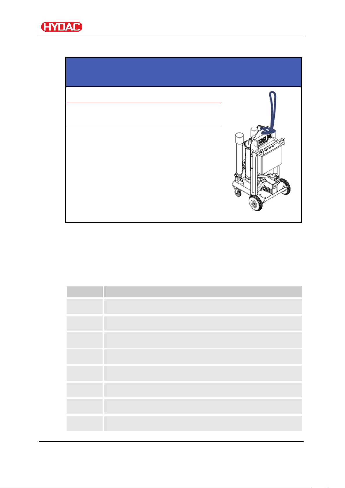
FluidAqua Mobil
Operating and Maintenance Instructions
English (translation of original instructions)
Documentation no.: 4166129

HYDAC FILTER SYSTEMS GMBH
Postfach 1251
66273 Sulzbach / Saarland
Germany
Telephone:
+49 6897 509 01
Fax:
+49 6897 509 9046
E-mail:
filtersystems@HYDAC.com
Homepage:
www.HYDAC.com
Court of Registration:
Saarbrücken, HRB 17216
Executive director:
Mathias Dieter,
Mr. Günter Harge
c/o HYDAC International GmbH, Industriegebiet, 66280 Sulzbach / Saar
Telephone:
+49 6897 509 1511
Fax:
+49 6897 509 1394
E-mail:
guenter.harge@HYDAC.com
Imprint
Publisher and responsible for the content:
Imprint
Dipl.Kfm. Wolfgang Haering
Documentation Representative
© HYDAC FILTER SYSTEMS GMBH
All rights reserved. No part of this work may be reproduced in any form (print,
photocopy or by other means) or processed, duplicated or distributed using
electronic systems without the written consent of the publisher.
These documents have been created and inspected with the greatest care.
However, errors cannot be ruled out completely.
FAM 5
BEWA FAM5 4166129 en-us 2016-07-28 te.doc 2016-07-28
en(us)
Page 2 / 114

Content
Imprint ............................................................................................................ 2
Documentation Representative ................................................................... 2
Content .......................................................................................................... 3
Preface ........................................................................................................... 7
Safety information ........................................................................................ 9
Content
Technical Support ........................................................................................ 7
Product modification .................................................................................... 7
Warranty ...................................................................................................... 7
Using the documentation ............................................................................. 8
Hazard symbols ........................................................................................... 9
Signal words and their meaning in the safety information and
instructions ................................................................................................ 10
Structure of the safety information and instructions ................................... 10
Observe regulatory information ................................................................. 11
Proper/Designated Use ............................................................................. 11
Improper Use or Use Deviating from Intended Use ................................... 12
Qualifications of personnel / target group .................................................. 13
Wear suitable clothing ............................................................................... 14
Stoppage in an emergency (EMERGENCY STOP) ................................... 14
Unpacking the FAM .................................................................................... 15
Transporting the FAM ................................................................................. 15
Horizontal transport ................................................................................... 15
Vertical transport ....................................................................................... 16
Transport suspended on a crane ............................................................... 17
Checking the scope of delivery ................................................................. 17
FAM description .......................................................................................... 18
FAM Versions ............................................................................................ 18
FAM features ............................................................................................. 19
FAM system components .......................................................................... 20
Dimensions – stationary unit ..................................................................... 22
Dimensions – mobile unit .......................................................................... 23
Hydraulic circuit .......................................................................................... 24
FAM 5
BEWA FAM5 4166129 en-us 2016-07-28 te.doc 2016-07-28
en(us)
Page 3 / 114

Content
Working principle of FAM .......................................................................... 25
Possible applications ................................................................................. 26
Bypass purification ................................................................................. 26
Transfer by Pumping .............................................................................. 26
FAM set-up and connection ....................................................................... 27
Setting up the FAM .................................................................................... 27
Notes on pipes and hoses ......................................................................... 28
Connecting the inlet (IN) ......................................................................... 30
Connect outlet (OUT) ............................................................................. 31
Preparing the Vacuum Pump ..................................................................... 31
Check air outlet of the vacuum pump ..................................................... 32
Electrical connection of the FAM ............................................................... 32
Check direction of rotation ......................................................................... 33
Operating elements on the FAM ................................................................ 34
Starting up the unit ..................................................................................... 36
Switching on the FAM ................................................................................ 36
FAM start screen (HOME) and menu layout .............................................. 37
Starting operation of the FAM .................................................................... 38
Setting the pressure in the vacuum column ............................................... 40
Recommended vacuum setting .............................................................. 40
Pressure information in the vacuum range .......................................... 42
Venting the filter housing ........................................................................... 43
Switching on the heater / Checking setting (optional) ................................ 43
Stopping operation of the FAM .................................................................. 45
Switching off FAM ....................................................................................... 46
Selecting operating mode .......................................................................... 46
"Dewater" operating mode (optional) ......................................................... 47
"Filter" operating mode (optional) .............................................................. 49
Limits on ContaminationSensor CS ........................................................ 49
ContaminationSensor CS1000 menu layout .......................................... 51
Setting times for "Dewater/Filter until" (optional) ....................................... 52
"Heat" operating mode (optional) ............................................................... 53
Manual Operation ...................................................................................... 54
Emptying the vacuum column ................................................................ 54
Manually controlling components ........................................................... 55
Settings – Language, operating hours, program version ....................... 56
FAM 5
BEWA FAM5 4166129 en-us 2016-07-28 te.doc 2016-07-28
en(us)
Page 4 / 114

Content
Loading new program version/language version .................................... 57
Inserting micro-SD card and loading program ........................................... 57
Configuration menu .................................................................................... 58
Changing configuration .............................................................................. 59
Exiting the Configuration menu .................................................................. 59
FAM menu layout ........................................................................................ 60
Changing values and parameters in menus ............................................. 61
Connection of an external AquaSensor AS(EXT) ..................................... 61
Network connection (Ethernet) .................................................................. 62
Web server ................................................................................................ 62
Troubleshooting .......................................................................................... 66
Error notifications ....................................................................................... 68
03 Empty vacuum column ...................................................................... 69
04 Vacuum pump level sensor ............................................................... 70
05 Vacuum column sensor ..................................................................... 71
12 Measured AS temp value/13 Measured AS %S value ...................... 72
18 H pump motor protection switch/19 V pump motor protection
switch V-pump ........................................................................................ 73
23 Filter clogged ..................................................................................... 74
24 V pump min. ...................................................................................... 75
25 V pump max. ..................................................................................... 75
26 Heater thermostat .............................................................................. 76
28 Heater motor protection switch .......................................................... 77
32 Fill column ......................................................................................... 79
33 Vacuum column alarm ....................................................................... 80
34 Drip tray full ....................................................................................... 81
Performing maintenance ........................................................................... 82
Maintenance intervals ................................................................................ 82
Check fault signal lamps ............................................................................ 85
Change Air filter ......................................................................................... 85
Vacuum pump ........................................................................................... 85
Replace the active carbon filter cartridge (accessory) ............................ 85
Rotary vane vacuum pump FAM-5-x-x-x-xx-R-x-x-x-x ........................... 86
Checking the oil level .......................................................................... 87
Filling/Refilling vacuum pump oil ........................................................ 88
Emptying the vacuum pump ................................................................ 90
FAM 5
BEWA FAM5 4166129 en-us 2016-07-28 te.doc 2016-07-28
en(us)
Page 5 / 114

Content
Changing the vacuum pump oil ........................................................... 91
Replacing the air de-oiling element of the vacuum pump .................... 92
Dry-running rotary vane vacuum pump FAM-5-x-x-x-xx-RD-x-x-x-
x ............................................................................................................. 93
Replacing the filter .............................................................................. 94
Blowing off the filter ............................................................................. 94
Inspecting/replacing vanes .................................................................. 95
Clean the suction screen ........................................................................... 96
Replacing the filter element on the fluid filter ............................................. 96
Heater maintenance (optional) ................................................................ 101
Inspecting/Cleaning the heating element ............................................. 101
Removing/Installing the heating element .......................................... 101
Emptying the heater ............................................................................. 103
Checking the AquaSensor AS1000 ......................................................... 104
Checking the float switch in the oil pan .................................................... 104
Spare parts ................................................................................................ 106
FAM ......................................................................................................... 106
Fluid filter (OLF 5/10) ............................................................................... 106
Vacuum pump ......................................................................................... 106
Rotary vane vacuum pump FAM-5-x-x-x-xx-R-x-x-x-x ......................... 106
Dry-running rotary vane vacuum pump FAM-5-x-x-x-xx-RD-x-x-x-
x ........................................................................................................... 107
Contact / Service ....................................................................................... 107
Storing the unit / taking it out of operation ............................................ 107
Disposing of the unit ................................................................................ 108
Technical data ........................................................................................... 108
Connection overview ................................................................................ 110
Model code ................................................................................................ 111
EC declaration of conformity ................................................................... 112
FAM 5
BEWA FAM5 4166129 en-us 2016-07-28 te.doc 2016-07-28
en(us)
Page 6 / 114

Fax:
+49 6897 509 9046
E-mail:
filtersystems@HYDAC.com
Preface
These operating instructions were made to the best of our knowledge.
Nevertheless and despite the greatest care, it cannot be excluded that
mistakes could have crept in. Therefore please understand that, in the
absence of any provisions to the contrary hereinafter, our warranty and
liability – for any legal reasons whatsoever – are excluded in respect of the
information in these operating instructions. In particular, we shall not be liable
for lost profit or other financial loss. This exclusion of liability does not apply
in cases of intent and gross negligence. Moreover, it does not apply to
defects which have been deceitfully concealed or whose absence has been
guaranteed, nor in cases of culpable harm to life, physical injury and damage
to health. If we negligently breach any material contractual obligation, our
liability shall be limited to foreseeable damage. Claims due to Product
Liability shall remain unaffected.
Technical Support
Preface
Contact our technical sales department if you have any questions on our
product. When contacting us, please always include the model code, serial
no. and part no. of the product:
Product modification
We would like to point out that changes to the product (e.g. purchasing
options, etc.) may result in the information in the operating instructions no
longer being completely accurate or sufficient.
After modification or repair work that affects the safety of the product has
been carried out on components, the product may not be returned to
operation until it has been checked and released by a HYDAC technician.
Please notify us immediately of any modifications made to the product
whether by you or a third party.
Warranty
For the warranty provided by us, please refer to the General Terms of Sale
and Delivery of HYDAC FILTER SYSTEMS GMBH.
You will find these under www.HYDAC.com -> General Terms and
Conditions.
FAM 5
BEWA FAM5 4166129 en-us 2016-07-28 te.doc 2016-07-28
en(us)
Page 7 / 114
Note that the method described for locating specific information
de
HYD
A
C
F
i
l
t
e
r
t
e
c
h
n
i
k
G
m
b
H
B
e
W
a
1
2
3
4
5
6
a
d
e
Seite x
P
r
o
d
u
k
t
/
K
a
p
i
t
e
l
200x-xx-xx
Chapter description
Page number
Document language
Documentation No.
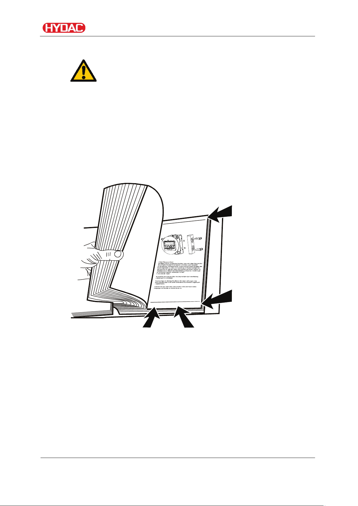
Using the documentation
does not release you from your responsibility of carefully reading
all these instructions prior to starting the unit up for the first time
and at regular intervals in the future.
What do I want to know?
I determine which topic I am looking for.
WHERE can I find the information I’m looking for?
The documentation has a table of contents at the beginning. There, I select
the chapter I'm looking for and the corresponding page number.
Safety information
Edition date
with Index /
File name
The documentation number with its index enables you to order another copy
of the operating and maintenance instructions. The index is incremented
every time the manual is revised or changed.
FAM 5
BEWA FAM5 4166129 en-us 2016-07-28 te.doc 2016-07-28
en(us)
Page 8 / 114
Safety information
The unit was built according to the statutory provisions valid at the time of
delivery and satisfies current safety requirements.
Any residual hazards are indicated by safety information and instructions and
are described in the operating instructions.
Observe all safety and warning instructions attached to the unit. They must
always be complete and legible.
Do not operate the unit unless all the safety devices are present.
Secure the hazardous areas which may arise between the unit and other
equipment.
Maintain the unit inspection intervals prescribed by law.
Document the results in an inspection certificate and keep it until the next
inspection.
Safety information
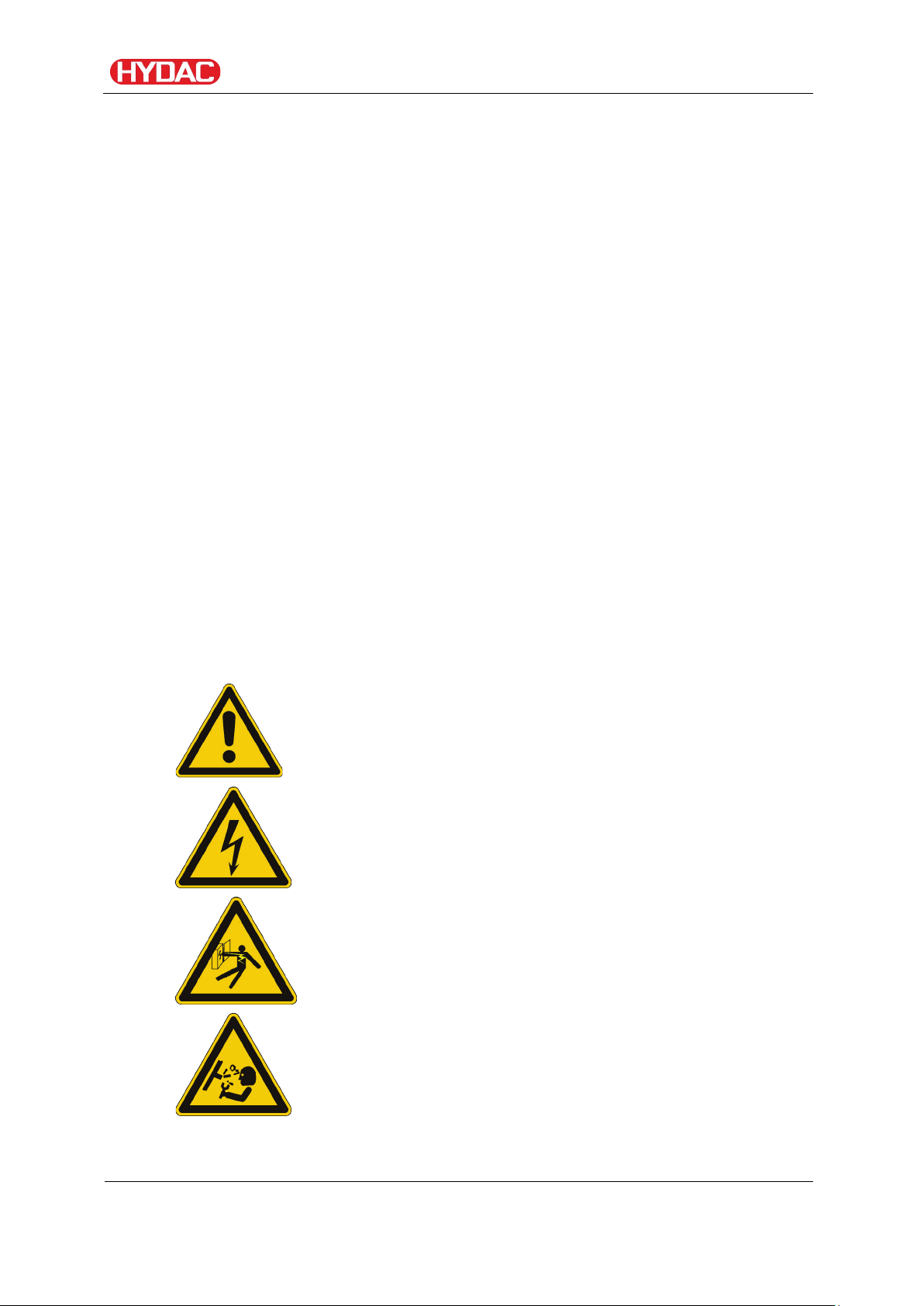
Hazard symbols
These symbols are listed for all safety information and instructions in these
operating instructions which indicate particular hazards to persons, property
or the environment.
Observe these instructions and act with particular caution in such cases.
Pass all safety information and instructions on to other users.
General hazard
Danger due to electrical voltage / current
Exposed electrical components
Danger of electrical shock
Danger due to operating pressure
FAM 5
BEWA FAM5 4166129 en-us 2016-07-28 te.doc 2016-07-28
en(us)
Page 9 / 114
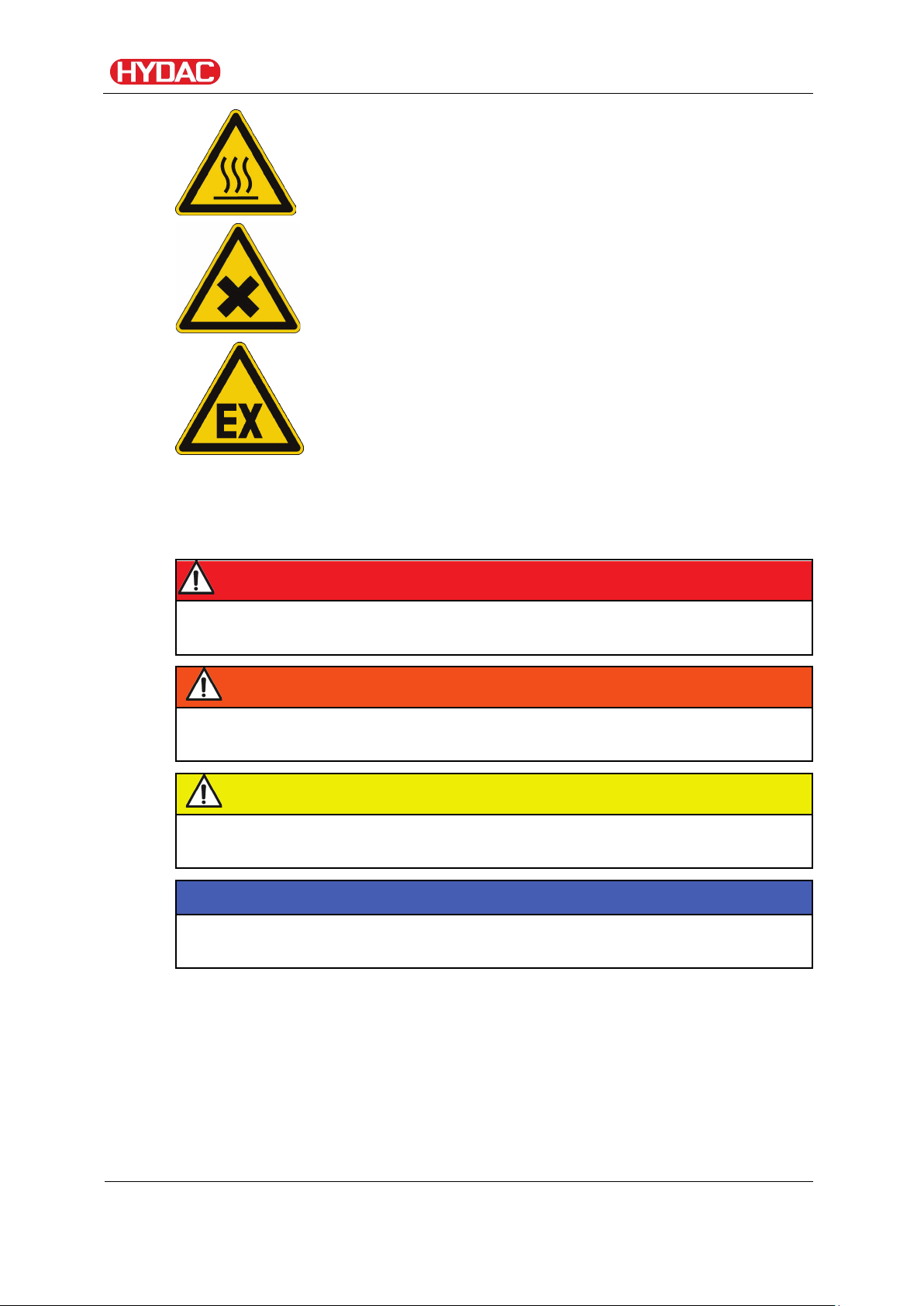
DANGER
DANGER indicates a danger with a high risk which will lead to death or
serious injury if not avoided.
WARNING
WARNING indicates a danger with a medium risk which can lead to death or
serious injury if not avoided.
CAUTION
CAUTION indicates a danger with a low risk which can lead to minor injury if
not avoided.
NOTICE
NOTICE indicates a danger which will lead to damage to property if not
avoided.
Safety information
Risk of burns due to hot surfaces
Substances that are health hazards or irritants
Danger from explosive atmosphere
Signal words and their meaning in the safety information and instructions
Structure of the safety information and instructions
All warning instructions in this manual are highlighted with pictograms and
signal words. The pictogram and the signal word indicate the severity of the
danger.
Warning instructions listed before an activity are laid out as follows:
FAM 5
BEWA FAM5 4166129 en-us 2016-07-28 te.doc 2016-07-28
en(us)
Page 10 / 114

F
S
o
m
Sealing
material
Hoses
FFAAMM--xxxx--MM-
-
MMiinneerraall ooiill,, tteesstteedd wwiitthh mmiinneerraall ooiill..
•• OOtthheerr hhyyddrraauulliicc aanndd lluubbrriiccaattiioonn ooiillss wwhhiicchh
NBR
NBR
HAZARD SYMBOL
SIGNAL WORD
Observe regulatory information
Observe the following regulatory information and guidelines:
• Legal and local regulations for accident prevention
• Legal and local regulations for environmental protection
• Country-specific regulations, organization-specific regulations
Safety information
Type and source of danger
Consequence of the danger
► Measures to avert danger
Proper/Designated Use
Use the unit only for the application described in the following.
The FAM is for dewatering, filtering and degassing hydraulic and lubricating
oils. In addition, it removes free water, emulsified water and a large
percentage of the water found in solution.
Proper or designated use of the product extends to the following:
• Observing all instructions contained in the instruction manual.
• performing inspection and maintenance work.
Depending on the version (see model code), you may use the FAM only in
connection with the following media:
e
e
p
p
y
y
t
t
M
M
A
A
e
e
l
l
b
b
a
a
t
t
i
i
u
u
g
g
n
n
i
i
m
m
t
t
u
u
a
a
i
i
r
r
d
d
e
e
e
e
p
p
……
•• MMiinneerraall ooiillss aacccc.. ttoo DDIINN 5500552244
•• GGeeaarr ooiillss aacccc.. ttoo DDIINN 5511551177,, 5511552244
FAM 5
BEWA FAM5 4166129 en-us 2016-07-28 te.doc 2016-07-28
en(us)
Page 11 / 114
rreeqquuiirree oorr aarree ccoommppaattiibbllee wwiitthh NNBBRR sseeaallss
FFAAMM--xxxx--II--……
IInnssuullaattiioonn ooiill,, cchheecckkeedd wwiitthh ((ee..gg.. SShheellll DDiiaallaa))..
NBR
NBR
FFAAMM--xxxx--BB--……
BBiioollooggiiccaallllyy tteesstteedd wwiitthh ffaasstt--bbiiooddeeggrraaddiinngg
FKM
NBR
FFAAMM--xxxx--XX--……
HHFFDD--RR fflluuiiddss,, tteesstteedd wwiitthh ((ee..gg.. FFyyrrqquueell))..
FKM
UPE/
Safety information
•• MMiinneerraall ooiillss aacccc.. ttoo DDIINN 5500552244
•• GGeeaarr ooiillss aacccc.. ttoo DDIINN 5511551177,, 5511552244
•• OOtthheerr hhyyddrraauulliicc aanndd lluubbrriiccaattiioonn ooiillss wwhhiicchh
rreeqquuiirree oorr aarree ccoommppaattiibbllee wwiitthh NNBBRR sseeaallss
UUnniitt iiss nnoott ssuuiittaabbllee ffoorr ""OOnnlliinnee"" aanndd ""OOnnllooaadd""
ooppeerraattiioonn oonn ttrraannssffoorrmmeerr..
fflluuiidd oonn aann eesstteerr bbaassiiss..
•• SSyynntthheettiicc eesstteerr ((HHEEEESS)) DDIINN 5511552244//22
•• VVeeggeettaabbllee ooiillss ((HHEETTGG,, HHTTGG))
•• HHyyddrraauulliicc aanndd lluubbrriiccaattiioonn ooiillss wwhhiicchh
rreeqquuiirree oorr aarree ccoommppaattiibbllee wwiitthh VViittoonn sseeaallss..
NNoott ffoorr pphhoosspphhaattee eesstteerrss tthhaatt rreeqquuiirree EEPPDDMM
sseeaallss..
(FPM,
Viton®)
(FPM,
Viton®)
PEPA
Improper Use or Use Deviating from Intended Use
Any use extending beyond this or deviating therefrom shall not be considered
intended use. HYDAC Filter Systems GmbH will assume no liability for any
damage resulting from such use. The owner alone, shall assume any and all
associated risk
DANGER
Danger due to unanticipated use of the unit
Bodily injury and damage to property will result
when operated improperly.
► Never operate the unit in potentially
explosive atmospheres.
► The unit is only to be used with permissible
media.
FAM 5
BEWA FAM5 4166129 en-us 2016-07-28 te.doc 2016-07-28
en(us)
Page 12 / 114

Activity
Person
Knowledge
Transport / storage
Forwarding
• Proof of knowledge of
Hydraulic / electrical
Specialist
• Safe handling/use of
• Checking the phase
Improper use or use deviating from intended may result in hazards and/or will
damage the unit. Examples of improper use:
• Operation in potentially explosive atmospheres.
• Operation with a non-approved medium.
• Operation under non-approved operational conditions.
• Operation when the safety devices are defective.
• Modifications to the power unit made by the user or purchaser.
• Inadequate monitoring of parts that are subject to wear and tear
• Improperly performed repair work.
Qualifications of personnel / target group
Persons who work on the power unit must be aware of the associated
hazards when using the power unit.
Operating and specialist personnel must have read and understood the
operating instructions, in particular the safety information and instructions,
and applicable regulations before beginning work.
Safety information
The operating instructions and applicable regulations are to kept so they are
accessible for operating and specialist personnel.
These operating instructions are intended for:
Operating personnel: such persons have been instructed in power unit
operation and are aware of potential hazards due to improper use.
Specialist personnel: such persons with corresponding specialist training and
several years work experience. They are able to assess and perform the
work assigned to them, they are also able to recognize potential hazards.
agent
Specialist
personnel
cargo securing
instructions
• Safe handling/operation
of hoisting and lifting
equipment
installation,
personnel
tools
FAM 5
BEWA FAM5 4166129 en-us 2016-07-28 te.doc 2016-07-28
first commissioning,
maintenance,
troubleshooting,
repair,
decommissioning,
en(us)
• Fitting and connection of
hydraulic lines and
connections
• Fitting and connection of
electrical lines, electrical
machinery, sockets, etc.
Page 13 / 114
Disassembly
sequence
Operation
Specialist
• Product-specific
Disposal
Specialist
• Proper and
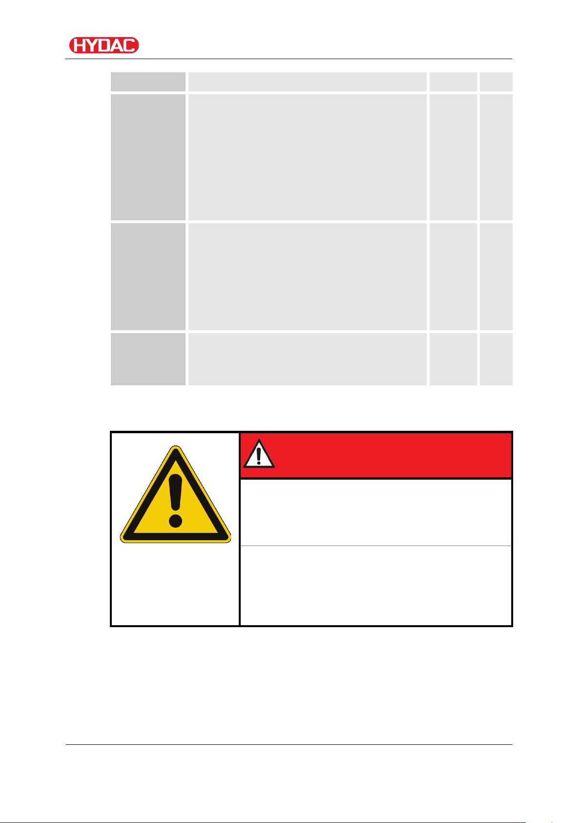
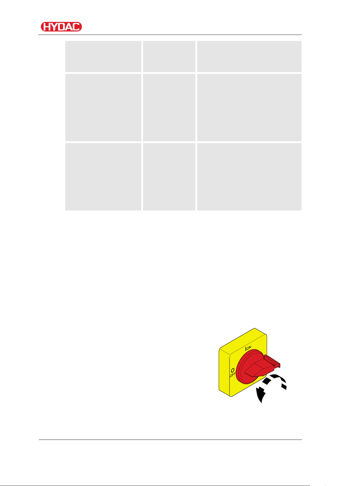
In the event of an emergency, turn the main
clockwise direction to
Safety information
• Product-specific
knowledge
Operations control
Wear suitable clothing
Loosely worn clothing increases the danger of getting caught or wound up in
rotating parts and the danger of getting snagged on projecting parts. You can
be severely injured or killed.
personnel
personnel
knowledge
• Knowledge about how to
handle operating media.
• Knowledge about
contamination due to
solids and water
environmentally-friendly
disposal of materials and
substances
• Decontamination of
contaminants
• Knowledge about reuse
• Wear close-fitting clothing.
• Do not wear any rings, chains or any other jewelry.
• Wear work safety shoes.
Stoppage in an emergency (EMERGENCY STOP)
switch by 90° in a countershut down the entire unit. The entire unit
downstream of this switch is voltage-free and
depressurized.
Normal pressure is restored to the vacuum column after ≈ 1 minute.
FAM 5
BEWA FAM5 4166129 en-us 2016-07-28 te.doc 2016-07-28
en(us)
Page 14 / 114
Unpacking the FAM
Before delivery, the FAM is inspected for leaks and proper functioning at the
factory, then carefully packed for shipment.
When receiving and unpacking the unit, check it for damage in transit.
Dispose of the packaging material in an environmentally friendly manner.
Transporting the FAM
Using components for pushing/pulling
The FAM will be damaged
► Never use the components to push or pull the FAM.
Unpacking the FAM
NOTICE
► Use the grips provided for shifting.
Wind the suction and pressure hose and the connection cable around the
holders provided for this purpose and either fasten them in place or remove
the hoses from the FAM.
Move the FAM manually using the rollers. Only ever use the FAMs handle to
move it.
Before shifting the unit, make sure to release the hand brake on the swivel
casters.
Once the FAM is in the new, desired position, actuate the hand brake on the
swivel casters.
Horizontal transport
Completely empty the FAM as well as the rotary vane vacuum pump before
horizontal transport, e.g., in a vehicle, and close off all connections.
FAM 5
BEWA FAM5 4166129 en-us 2016-07-28 te.doc 2016-07-28
en(us)
Page 15 / 114
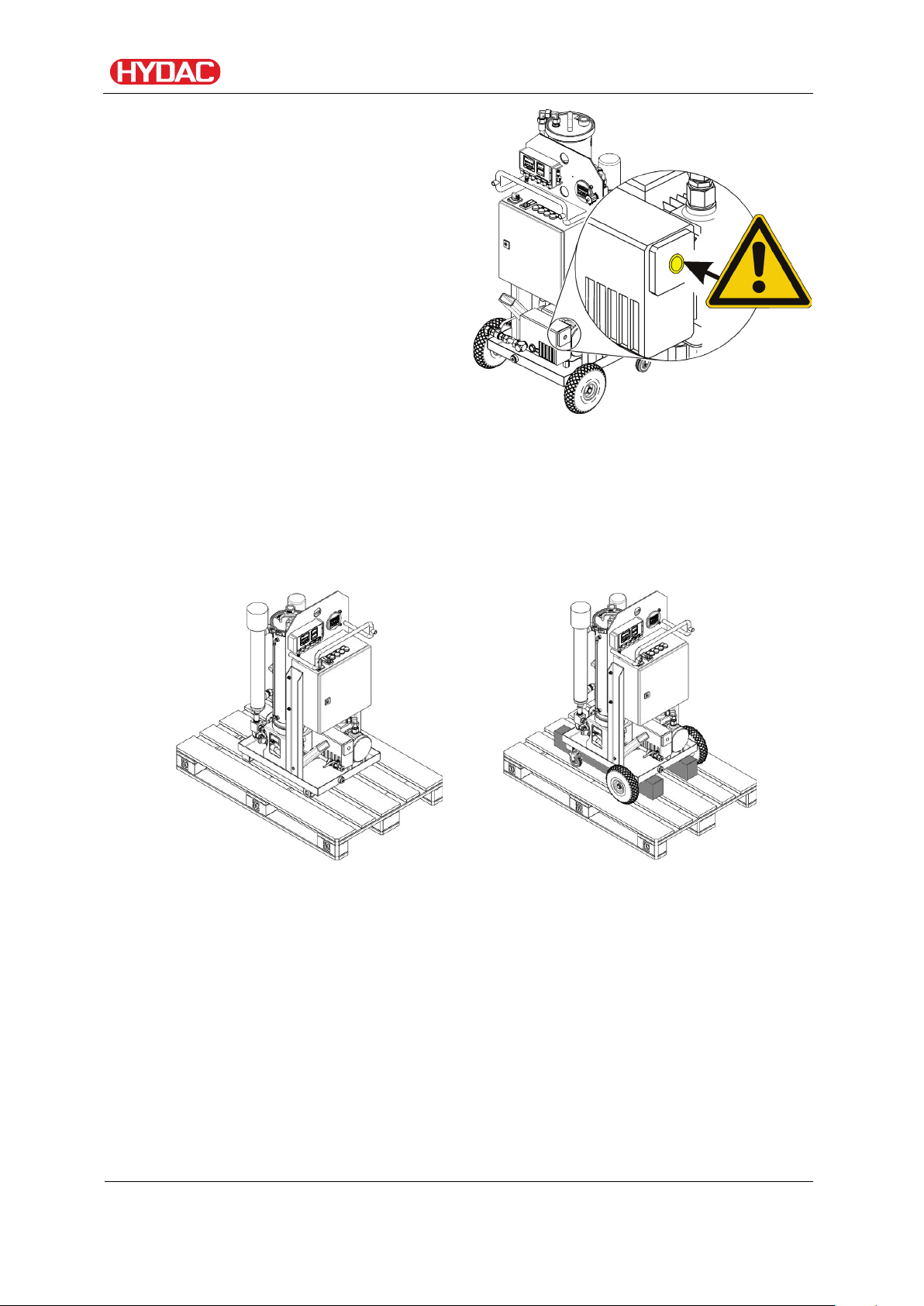
Close the air outlet of the vacuum
Stationary version
Mobile version
pump using the matching suitable
screw plugs.
Ensure the FAM is fixed tight to the car using load restraint belts at the
suitable lashing points in the car.
Vertical transport
Transporting the FAM
For transport by rail or truck, supports must be placed under the mobile FAM
so that none of the rollers are subjected to load pressure. Secure the FAM
with suitable belts.
FAM 5
BEWA FAM5 4166129 en-us 2016-07-28 te.doc 2016-07-28
en(us)
Page 16 / 114
Qty
Designation
Transport suspended on a crane
NOTICE
Unsuitable lifting accessories
The unit/components will be
damaged/destroyed
► Use only suitable lifting accessories to
raise or lash the FAM.
► Take care to ensure that the lifting
accessories do not cause any pressures to
be brought to bear against the components
on the FAM.
Checking the scope of delivery
Checking the scope of delivery
Upon receiving the FAM check it for any damage in transit. Immediately
report any damage in transit to the forwarding agent or the HYDAC
department in charge.
The following items are supplied:
1
1
1
1
1
FluidAqua Mobil
Key to the control cabinet
Vacuum pump oil, 1 liter (FAM-5-x-x-x-x-R-x-x-x-x only)
Suction and return hose (mobile FAM-5-x-2-… only)
Operation and Maintenance Instructions (this document)
1
1
1
FAM 5
BEWA FAM5 4166129 en-us 2016-07-28 te.doc 2016-07-28
Electrical wiring diagram situated in the control cabinet
EC declaration of conformity
Test certificate
en(us)
Page 17 / 114
-
2x
Wheels
-
2x
Swivel casters
-
1x
Suction hose
-
1x
Return hose
FAM description
The FluidAqua FAM was developed for the dewatering, filtration and
degassing of hydraulic and lubricating oils. It removes free water, emulsified
water and a large proportion of the water in solution. The Fluidfilter that is
installed provides efficient particulate separation.
The fluid is degassed through a vacuum in the vacuum chamber.
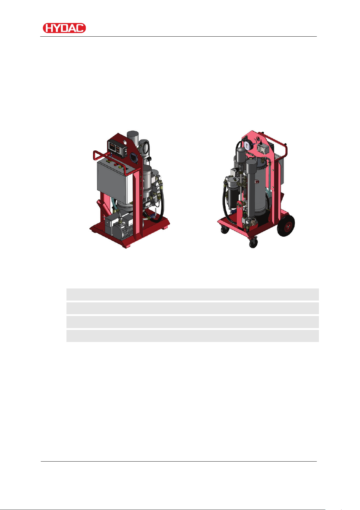
FAM Versions
FAM description
Stationary (FAM-x-1-..) Mobile (FAM-x-2-..)
In comparison to the stationary version, the mobile version of the FAM also
has:
FAM 5
BEWA FAM5 4166129 en-us 2016-07-28 te.doc 2016-07-28
en(us)
Page 18 / 114
Hydraulic and lubrication oils
<100 ppm
Turbine oil (ISO VG32/46)
< 50 ppm
Transformer oil (unit is not suitable for "Online" and
<10 ppm
Dewatering speed
Water content
Fluid temperature
Detergent additives
Tank volume in liters
Filter Size
< 2,000
FAM 5
1,000 … 7,000
FAM 10, FAM 10/15
7,000 … 15,000
FAM 25
15,000 … 25,000
FAM 45 / FAM-45E
25,000 … 35,000
FAM 60
35,000 … 45,000
FAM 75 / FAM-75E
> 45,000
FAM 95
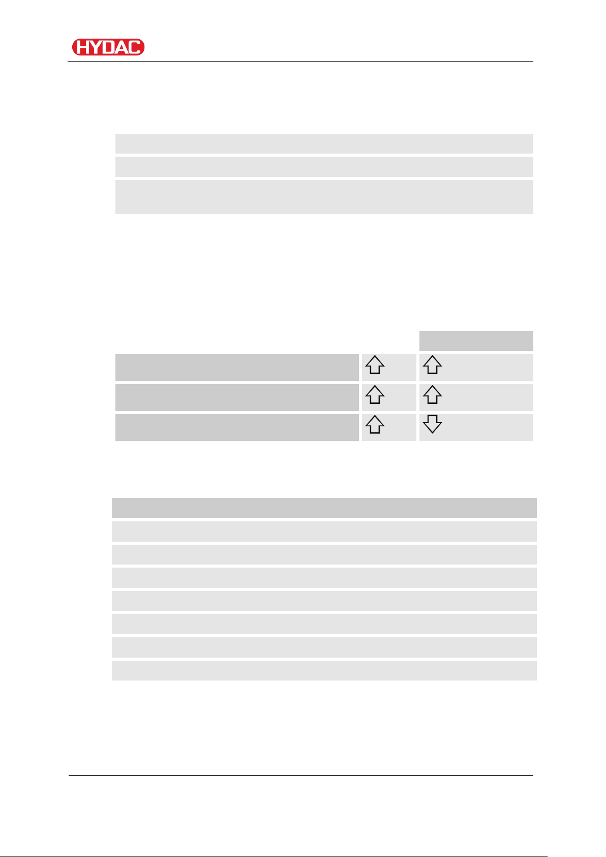
FAM features
The FAM is able to reduce fluids described in the chapter "Suitable fluids"
typically to the following attainable residual water contents:
"Onload" operation on transformer)
The typical dewatering rate is up to 0.8l/h at 1% (10,000 ppm) water content
(ISO VG32, 50°C).
Dewatering performance/Dewatering speed depends in particular on the oil
type, oil temperature, oil quantity, tank condition, water content and the
environmental conditions and can differ considerably from the indicated
values depending on use.
The dewatering speed is dependent on:
FAM description
As an approximate guideline, the dimensioning of the FluidAqua Mobil can be
defined in accordance with the tank volume.
Note that free water, e.g. on the bottom of the tank, can have an influence on
the entire water content in the system and thus on the length of time it takes
to dewater. Drain off free water completely.
FAM 5
BEWA FAM5 4166129 en-us 2016-07-28 te.doc 2016-07-28
en(us)
Page 19 / 114
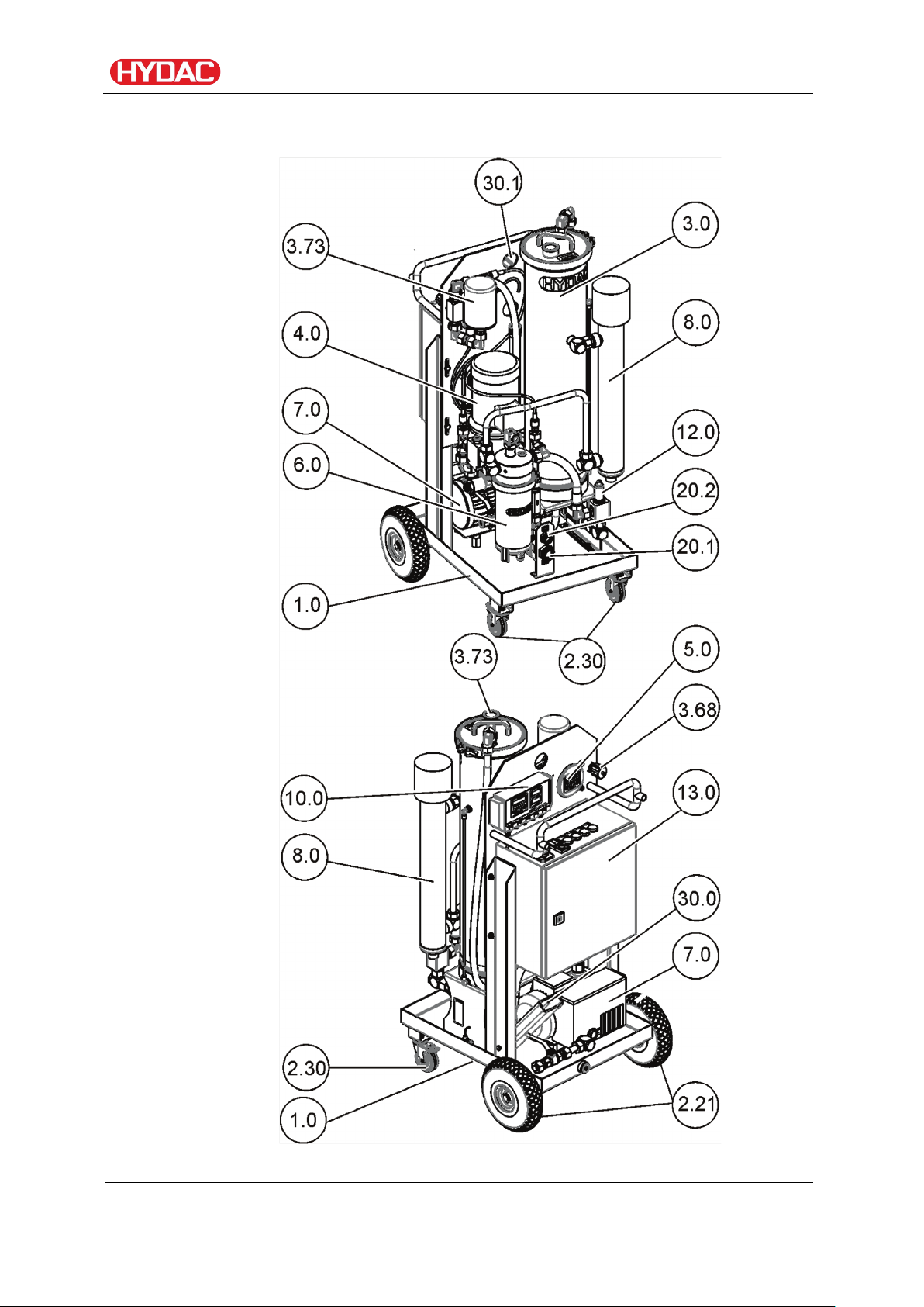
FAM system components
FAM description
FAM 5
BEWA FAM5 4166129 en-us 2016-07-28 te.doc 2016-07-28
en(us)
Page 20 / 114

Item
Designation
1.0
Drip tray
2.21
Pneumatic tire
(mobile version only)
2.30
Guide roll
(mobile version only)
3.0
Vacuum column
3.68
Vacuum gauge
3.73
Air filter
3.85
3/2-directional control valve
4.0
Motor pump assembly
5.0
ContaminationSensor CS
(optional)
6.0
Fluid filter for separating solid particles
OLF5
7.0
Vacuum pump
8.0
Heater
(optional)
10.0
SensorMonitoring Unit SMU
(optional)
12.0
AquaSensor AS
(optional)
13.0
Electrical switch box with main switch
20.1
Inlet
IN
20.2
Outlet
OUT
30.0
Holder for lances
(Accessories)
31.0
Lifting eye
FAM description
(underpressure setting in the vacuum
column)
FAM 5
BEWA FAM5 4166129 en-us 2016-07-28 te.doc 2016-07-28
en(us)
Page 21 / 114
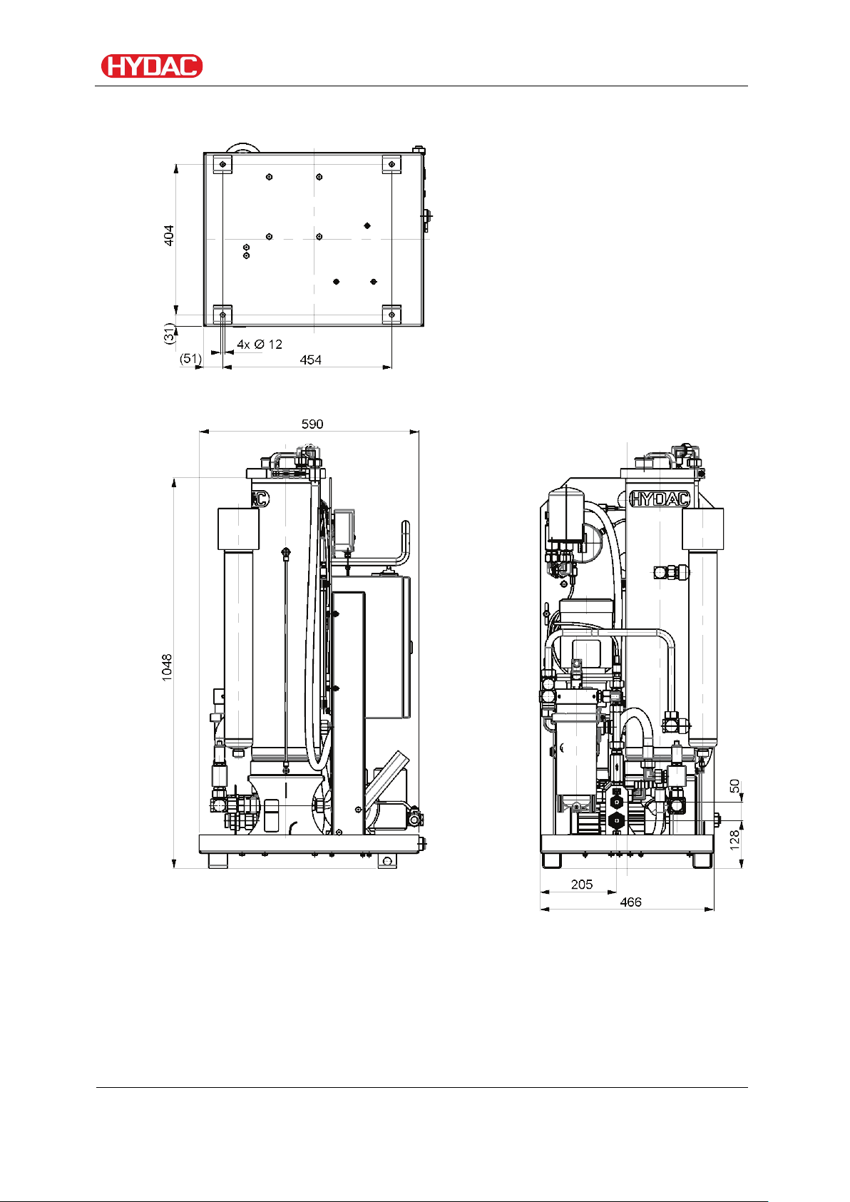
Dimensions – stationary unit
Dimensions – stationary unit
FAM 5
BEWA FAM5 4166129 en-us 2016-07-28 te.doc 2016-07-28
en(us)
Page 22 / 114
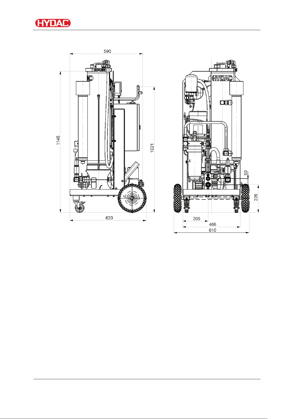
Dimensions – mobile unit
Dimensions – mobile unit
FAM 5
BEWA FAM5 4166129 en-us 2016-07-28 te.doc 2016-07-28
en(us)
Page 23 / 114
Einlass
Inlet
Auslass
Outlet
Entleerung
Drain
Lufteinlass
Air intake
Min.
Max.
Alarm
M
Entleerung
Drain
Luftauslass
Air outlet
1.04
1.0
3.68
3.73
3.38
3.0
4.0
4.02
4.54
6.0
7.0
6.23
AS
CS
M
3.37
DPI
Entleerung
Drain
Entlüftung
Vent
Entleerung
Drain
3.43
4.70
3.85
P
R A
8.0*
5.0*
12.0*
Optionale Bauteile
Optional components
x.x*
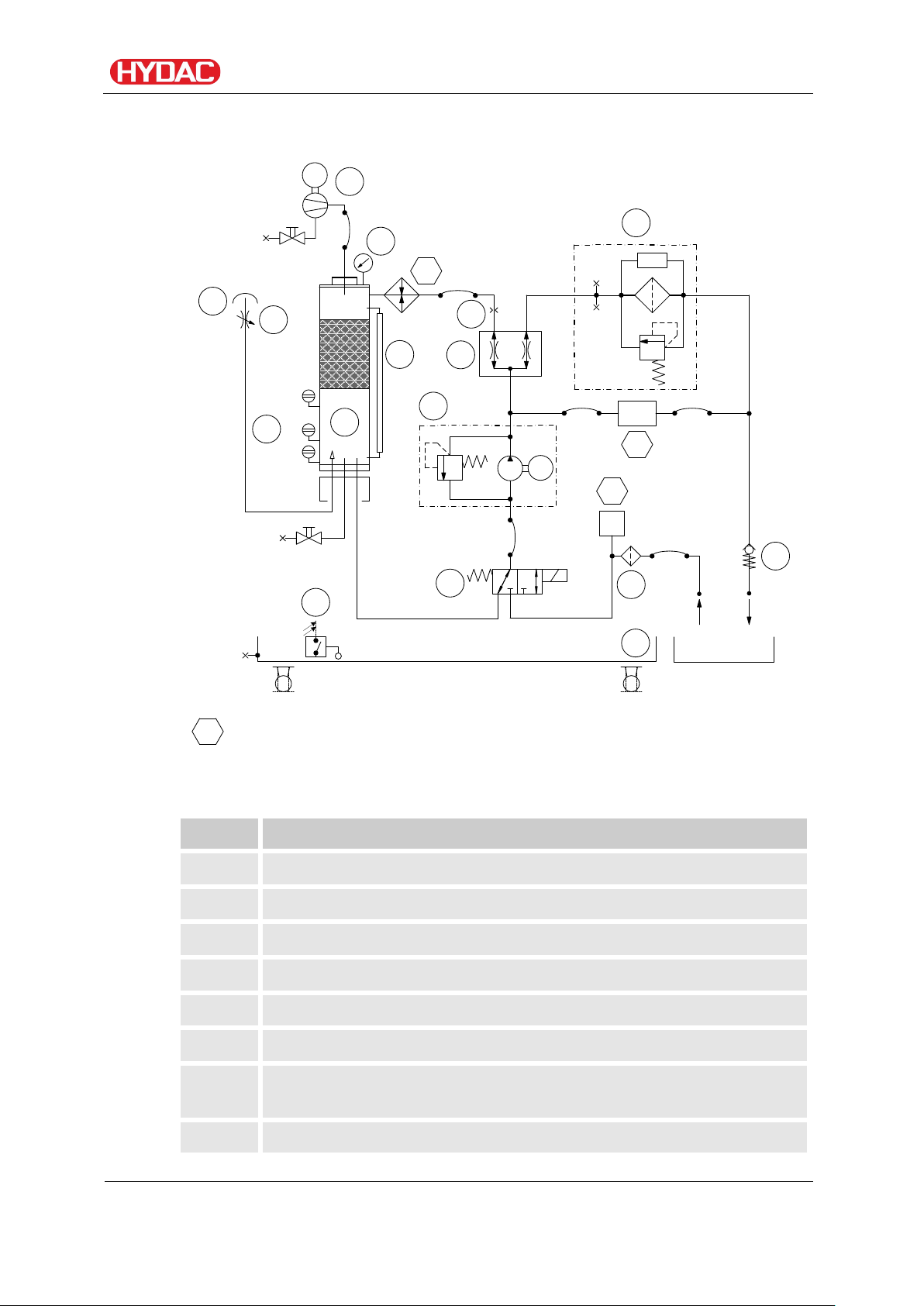
Item
Designation
1.0
Drip tray
1.04
Float switch in oil pan
3.0
Vacuum column
3.37
Vacuum pressure gauge
3.38
Level switch in the vacuum column
3.43
Fluid level indication of the vacuum column
Vacuum gauge
3.73
Air filter
Hydraulic circuit
Hydraulic circuit
3.68
(underpressure setting in the vacuum column)
FAM 5
BEWA FAM5 4166129 en-us 2016-07-28 te.doc 2016-07-28
en(us)
Page 24 / 114

3.85
3/2-directional control valve
4.0
Motor pump assembly
4.02
Suction strainer
4.54
Flow divider
4.70
Orifice
5.0
ContaminationSensor CS
(optional)
6.0
Fluid filter for separating solid particles
OLF5
6.23
Non-return valve
7.0
Vacuum pump
8.0
Heater
(optional)
12.0
AquaSensor AS
(optional)
Working principle of FAM
Working principle of FAM
After you switch on the FAM, the motor pump assembly (4.0), depending on
the fill level in the vacuum column, starts to suck either from the vacuum
column or the tank via the suction strainer (4.02) or from the vacuum column
and the 3/2 directional valve (3.85).
The flow rate is split up in the flow divider (4.54). One part is transported via
the optional heater (8.0) into the vacuum column (3.0), the other back into the
tank via the fluid filter (6.0).
The vacuum pump (7.0) builds up the negative pressure in the vacuum
column (3.0) required for dewatering and degassing.
The underpressure is set using the needle valve (3.68) and shown in the
pressure gauge on the cover of the vacuum column (3.0).
The fluid percolates downwards in the vacuum column (3.0) over a special
tower packing and collects in the lower area. After reaching the maximum
level (3.38), the 3/2 directional valve (3.85) will switch and the motor pump
assembly (4.0) will start sucking the oil out of vacuum column (3.0).
Air is drawn in through the air filter (3.73) as a result of the negative pressure
in the vacuum column (3.0). This air absorbs the moisture of the fluid and is
then sucked out by the vacuum pump (7.0). The gases removed from the
fluid as well as the water that is absorbed is expelled (as water vapor) from
the vacuum pump.
The saturation level of the aspirated fluid is continuously measured via the
optional AquaSensor (12) and displayed on the control panel. The saturation
level indicates what percent of maximum possible water is dissolved in the
FAM 5
BEWA FAM5 4166129 en-us 2016-07-28 te.doc 2016-07-28
en(us)
Page 25 / 114
In order to achieve optimum purity results, always operate the
oil. A value of 0% would indicate water-free oil and 100% would mean oil that
is completely saturated with water.
Once the STOP button is pressed, the unit runs until the "Min" fill level in the
vacuum column is reached. The run-down phase status is shown in the
display.
Exception: If the integrated heater is switched on, then a cooling phase of 60
seconds will intervene during which the heater is first shut off.
If the fill level "Min" in the vacuum column is reached, the power unit will be
switched off.
The FAM is voltage-free downstream from the main switch when the FAM is
switched off with the main switch.
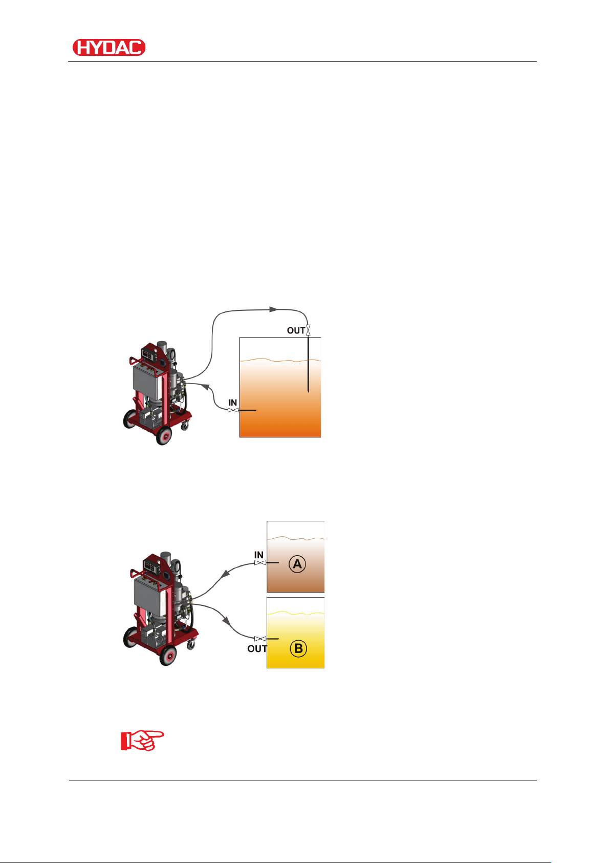
Possible applications
Bypass purification
Working principle of FAM
Attach the FAM to the tank which is to be cleaned by means of a suction and
pressure line and switch it on. The permanent bypass purification means you
always get optimum purity results.
Transfer by Pumping
Connect up the FAM to a contaminated oil tank by means of a suction line
and pump the fluid into the clean oil tank via the FAM.
To avoid overfilling the tank (B), permanently monitor the oil level.
FAM in bypass current after transfer by pumping.
FAM 5
BEWA FAM5 4166129 en-us 2016-07-28 te.doc 2016-07-28
en(us)
Page 26 / 114
FAM set-up and connection
Setting up the FAM
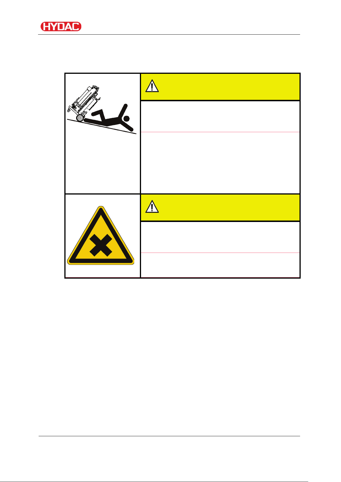
CAUTION
Danger of tipping on inclines
Crushing hazard
► Operate the power unit only on an even,
► Do not set the unit down on an inclined
► Always set the brakes on the swivel casters.
FAM set-up and connection
level surface.
surface.
CAUTION
Outlet air of the vacuum pump
Hazardous to health
► Always make sure there is sufficient
ventilation in the surrounding area of the unit.
Observe the following points when setting up the unit:
• Place the unit on a horizontal and level surface.
Special mounting is not required.
• Keep an area of at least 0.8 m around the unit free for maintenance
purposes.
• Mobile version only - Lock the immobilization brakes on the wheels to
avoid unintended movement/rolling away of the unit.
• Position the unit in the immediate vicinity of the tank to be cleaned.
Observe the maximum permitted suction pressure. See page 30.
• Observe the ambient temperature on the name plate of the unit.
• Ensure that the main switch is free and accessible at all times.
• Make sure there is sufficient ventilation around the area where the unit is
set up.
FAM 5
BEWA FAM5 4166129 en-us 2016-07-28 te.doc 2016-07-28
en(us)
Page 27 / 114
The hydraulic system must be depressurized
∆
Air coming out of the vacuum pump can contain particles of vacuum pump oil
and/or the fluid.
Depending on the composition of the oil and the composition of the gas,
there is a danger of damage to health if the emergent gas is inhaled over an
extended period of time.
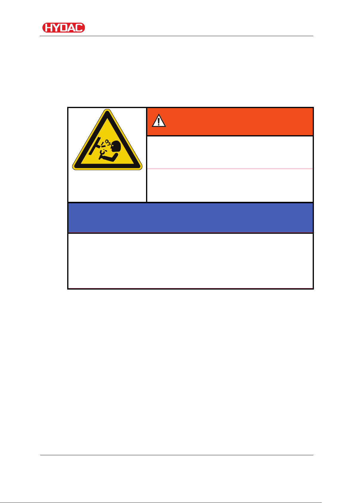
Notes on pipes and hoses
FAM set-up and connection
WARNING
Hydraulic systems are under pressure
Danger of bodily injury
►
before performing any work on the hydraulic
system.
NOTICE
Non-permitted pressure at the inlet IN/outlet OUT
Failure malfunction
► Determine the pressure to be anticipated at the inlet / outlet with the
prescribed values.
Note that the cross-section of the connected hoses/piping must be at least as
large as the cross-section of the inlet/outlet port sizes.
In order to keep the pressure loss as low as possible, use few threaded
connections.
The pressure at the inlet/outlet depends on the height differential between
the suction connection on the FAM and the fluid surface in the tank
(aspiration height ∆P
If the FAM is above the fluid surface in the tank, estimate the pressure as
follows: P = 1 bar - ∆P
) and the line losses (∆P
(height)
(height)
- ∆P
(line)
(line)
).
If the FAM is below the fluid surface in the tank, estimate the pressure as
follows: P = 1 bar - ∆P
Determine the pressure loss ∆P(height) as follows:
(height)
- ∆P
(line)
P
(height)
[bar] = h [m] / 10.
h stands here for the distance between the suction connection on the FAM
and the fluid surface in the tank and is given in meters.
For the sake of simplicity, these calculations assume an ambient pressure of
1 bar and a density of 1 kg/m³.
FAM 5
BEWA FAM5 4166129 en-us 2016-07-28 te.doc 2016-07-28
en(us)
Page 28 / 114
Δp(line) ≈ 6.8 * L / d4 * Q * V * D
Δp
=
Pressure differential in [bar]
L = pipe length [m]
d = internal pipe diameter [mm]
Q = Flow rate [l/min]
V = Kinematic viscosity [mm²/s]
D = Density [kg/dm³]
Mineral oil-based hydraulic oil has a density
Mineral hydraulic oil HLP
0.85 … 0.90
kg/dm³
Phosphate ester HFD-R
1.00 … 1.10
kg/dm³
Insulation oil
0.90 … 1.00
kg/dm³
Lubricating oil
0.90 … 0.95
kg/dm³
The pressure differential in a hydraulic line (∆P
FAM set-up and connection
) depends on the
(line)
following:
• flow rate
• kinematic viscosity
• Pipe dimensions
• Fluid density
The pressure loss in straight pipes (∆P
of ≈ 0.9 kg/dm³.
The density (D) is:
) can be calculated as follows:
(line)
Additional threaded connections and pipe bends increase the pressure
differential and must be taken into account.
Keep the height difference between the pump and the oil level in the tank as
small as possible.
Avoid constrictions in the connected hoses. They compromise output and
increase the risk of cavitation.
Make sure that no tension or vibrations are carried over to the pump or filter
housing when the pipes are connected. Use hoses or expansion joints if
necessary.
FAM 5
BEWA FAM5 4166129 en-us 2016-07-28 te.doc 2016-07-28
en(us)
Page 29 / 114
The greatest contamination is found on the bottom of the tank.
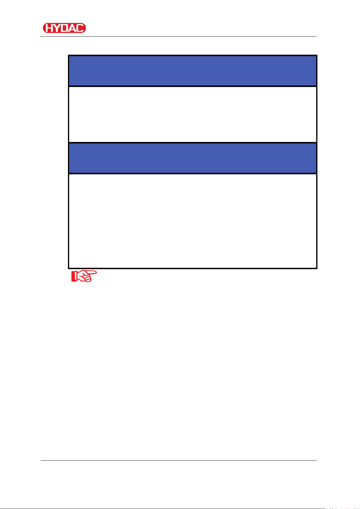
Connecting the inlet (IN)
Moving unsecured hoses / lances in the tank
The hoses/lances fall out of the tank
► Attach the hoses/lances to the tank and secure them against falling
out.
Contamination in the medium too high
The FAM will be damaged
FAM set-up and connection
NOTICE
NOTICE
► Do not prime directly at the bottom of the tank
► Do not prime in the sump
► Never prime without a built-in suction screen
► Never suck in free water
All impurities and other particles are deposited on the bottom of
the tank. All impurities like water or solid particles are deposited
on the bottom of the tank. Drain out the deposited, free water at
the bottom of the tank.
The suction pressure at the FAM inlet must be -0.2 bar.
Use a negative pressure-resistant, flexible hose or a pipe for the suction-side
connection.
Note that the cross-section of the connected hoses/piping must be at least as
large as the cross-section of the inlet/outlet port sizes.
The shape of the tank connection should be set up in such a way that it will
always be lower than the level of the oil.
FAM 5
BEWA FAM5 4166129 en-us 2016-07-28 te.doc 2016-07-28
en(us)
Page 30 / 114
 Loading...