

Page 1
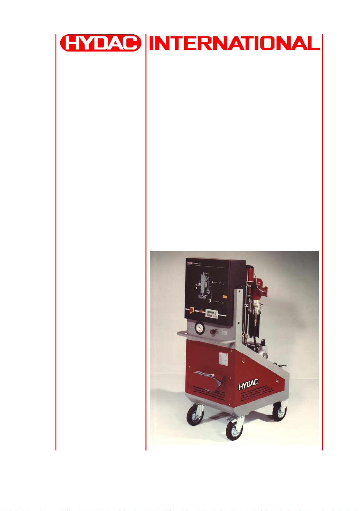
FAM 10/15 Series
FluidAqua Mobil
+ AquaSensor AS1000
+ ContaminationSensor CS 1000
Operating and Maintenance Instructions
English (translation of German original)
Dokumentation no.: 3417360
Page 2

FluidAqua Mobil – FAM 10/15 +CS1000 +AS1000 Trademarks
Trademarks
The trademarks of other companies are exclusively used for the products of those
companies.
Copyright © 2008 by
HYDAC Filtertechnik GmbH
all rights reserved
All rights reserved. This manual may not be reproduced in part or whole without the
explicit written agreement from HYDAC Filtertechnik. Contraventions are liable to
compensation.
Exclusion of liability
We made every endeavor to ensure the accuracy of the contents of this document.
However, errors cannot be ruled out. Consequently, we accept no liability for such
errors as may exist nor for any damage or loss whatsoever which may arise as a result of such errors. The content of the manual is checked regularly. Any corrections
required will be incorporated in future editions. We welcome any suggestions for improvements.
All details are subject to technical modifications.
Technical specifications are subject to change without notice.
HYDAC Filtertechnik GmbH
Industriegebiet
D-66280 Sulzbach / Saar
Germany
Phone: ++49 (0) 6897 / 509 – 01
Fax: ++49 (0) 6897 / 509 – 846
HYDAC Filtertechnik GmbH
BEWA FAM10 3417360 en.doc 2008-06-06
en
Page 2 / 80
Page 3

FluidAqua Mobil – FAM 10/15 +CS1000 +AS1000 Contents
Contents
Trademarks.............................................................................................................................2
Contents..................................................................................................................................3
Preface ....................................................................................................................................6
Customer Service ................................................................................................................. 7
Modifications to the Product .................................................................................................7
Warranty ............................................................................................................................... 7
Using the documentation ...................................................................................................... 8
Safety Information and Instructions.....................................................................................8
Obligations and Liability........................................................................................................9
Explanation of Symbols and Warnings ................................................................................. 9
General Safety Precautions................................................................................................ 10
Proper/Designated Use ......................................................................................................11
Improper Use ......................................................................................................................11
Safety Devices....................................................................................................................11
Informal Safety Precautions................................................................................................ 12
Training and Instruction of Personnel................................................................................. 13
Safety Measures to Be Followed during Normal Operation................................................ 13
Electrical Hazards............................................................................................................... 14
Maintenance, Servicing and Troubleshooting..................................................................... 14
Modifications to the FluidAqua Mobil ..................................................................................14
How to behave in case of emergency................................................................................. 15
Packing, Transportation......................................................................................................15
Unpacking the FAM ............................................................................................................ 15
Transporting the FAM ......................................................................................................... 15
Moving the FAM ..............................................................................................................16
Scope of Delivery.................................................................................................................17
FAM Description...................................................................................................................18
FAM components................................................................................................................ 19
Hydraulic schematic............................................................................................................20
Technical specifications......................................................................................................21
Suitable Fluids .................................................................................................................... 21
FAM Function description ................................................................................................... 22
Possible Applications.......................................................................................................... 22
Bypass purification (dewatering, filtration and degassing).............................................. 23
Transfer by pumping (dewatering, filtration and degassing) ........................................... 23
FAM Set-up and Connection ...............................................................................................24
Setting up the FAM ............................................................................................................. 24
Hydraulic Connection of the FAM .......................................................................................24
Connecting the suction port connection (IN)................................................................... 24
HYDAC Filtertechnik GmbH
BEWA FAM10 3417360 en.doc 2008-06-06
en
Page 3 / 80
Page 4

FluidAqua Mobil – FAM 10/15 +CS1000 +AS1000 Contents
Connecting the return port connection (OUT) ................................................................. 24
Preparing the Vacuum Pump.............................................................................................. 25
Checking the settings on the heater (optional) ................................................................... 26
Electrical Connection of the FAM .......................................................................................27
Starting up the FAM.............................................................................................................28
Switching on the FAM......................................................................................................... 28
Shutting off the FAM ........................................................................................................... 29
Control Panel - SIMATIC PANEL .......................................................................................30
Operating the FAM from the Control Panel ........................................................................30
Start screen..................................................................................................................... 31
Menu1 ............................................................................................................................. 32
Menu2 ............................................................................................................................. 32
Operating Mode (OM) ..................................................................................................... 33
Manual Menu (MANUAL) ................................................................................................ 34
OPERATOR (MANUAL1)................................................................................................ 35
OPERATOR (MANUAL2)................................................................................................ 35
LANGUAGE .................................................................................................................... 36
RH+P (Relative Humidity + Pressure)............................................................................. 37
Contamination (Selection Contamination)....................................................................... 38
ISO.................................................................................................................................. 38
Intervals...........................................................................................................................39
an operating-hours counter, and..................................................................................... 40
Operating Mode "Cleaning until" ..................................................................................... 40
General Operating Instructions - SIEMENS PANEL........................................................... 41
System Keys ................................................................................................................... 41
Entries and Help.............................................................................................................. 42
Numerical Values ........................................................................................................42
Alphanumerical Values................................................................................................ 42
Date and Time ............................................................................................................. 42
Entering and Modifying Numerical and Alphanumerical Values.................................. 43
Enter Value.................................................................................................................. 44
Partial Value Changes................................................................................................. 44
Character Call-up Sequence .......................................................................................44
Entering and Changing Date and Time .......................................................................46
Safety Queries............................................................................................................. 46
Error messages....................................................................................................................48
Vacuum Chamber Overflow................................................................................................ 52
FAM tray too full..................................................................................................................53
FAM outlet blocked ............................................................................................................. 54
FAM entry blocked..............................................................................................................55
Dry-running Evacuation Pump............................................................................................ 56
Dry run drain pump .............................................................................................................57
HYDAC Filtertechnik GmbH
BEWA FAM10 3417360 en.doc 2008-06-06
en
Page 4 / 80
Page 5

FluidAqua Mobil – FAM 10/15 +CS1000 +AS1000 Contents
Fault on vacuum column level probe .................................................................................. 58
Level switch in the vacuum pump....................................................................................... 59
Oil filter contaminated .........................................................................................................60
Motor Protection Switch...................................................................................................... 61
Cable break ........................................................................................................................ 63
Safety thermostat................................................................................................................65
Electrical fuses....................................................................................................................67
Reset safety thermostat on the heater (Optional)............................................................... 68
Maintenance..........................................................................................................................69
Visual checks...................................................................................................................... 69
Vacuum pump.....................................................................................................................69
Rotary Vane Vacuum Pump ...............................................................................................70
Changing oil and oil filter.................................................................................................71
Replacing the Air De-oiling Element ...............................................................................71
Clean the suction strainer. .................................................................................................. 72
Fluid filter (OLF-5)...............................................................................................................72
Changing the Filter Element............................................................................................ 72
Heater (Option) ................................................................................................................... 73
Storing the FAM....................................................................................................................73
Disposing of the FAM ..........................................................................................................73
Technical data ......................................................................................................................74
Type label ........................................................................................................................... 75
Spare parts............................................................................................................................76
FAM 10 ............................................................................................................................... 76
Fluid filter (OLF 5/10)..........................................................................................................76
Vacuum pump.....................................................................................................................76
HYDAC Filtertechnik GmbH
BEWA FAM10 3417360 en.doc 2008-06-06
en
Page 5 / 80
Page 6

FluidAqua Mobil – FAM 10/15 +CS1000 +AS1000 Preface
Preface
For you, as the owner of a product manufactured by us, we have produced this
manual, comprising the most important instructions for its operation and mainte-
nance.
It will acquaint you with the product and assist you in using it as intended in an optimal manner.
Keep it in the vicinity of the product so it is always available.
Note that the information on the unit's engineering contained in the documentation
was that available at the time of publication. There may be deviations in technical
details, figures, and dimensions as a result.
If you discover errors while reading the documentation or have additional comments
or suggestions, contact us at:
HYDAC Filtertechnik GmbH
Division Service technology / Filter systems
Technical Documentation Department
Postfach 12 51
66273 Sulzbach/Saar - Germany
Fax: ++49 (0) 6897 509 846
Email: filtersysteme@hydac.com
We look forward to receiving your input.
“Putting experience into practice”
HYDAC Filtertechnik GmbH
BEWA FAM10 3417360 en.doc 2008-06-06
en
Page 6 / 80
Page 7

FluidAqua Mobil – FAM 10/15 +CS1000 +AS1000 Preface
Customer Service
Contact our technical sales department if you have any questions on our product.
When contacting us, please always include the model/type designation, serial no.
and part-no. of the product:
Fax: ++49 (0) 6897 509 846
Email: filtersysteme@hydac.com
Modifications to the Product
We would like to point out that changes to the product (e.g. purchasing additional
options, etc.) may mean that the information in the operating instructions is no
longer applicable or adequate.
After modification or repair work that affects the safety of the product has been carried out on components, the product may not be returned to operation until it has
been checked and released by a HYDAC technician.
Please notify us immediately of any modifications made to the product whether by
you or a third party.
Warranty
For the warranty provided by us, please refer to the General Terms of Sale and Delivery of HYDAC Filtertechnik GmbH.
They are available at:
www.hydac.com Legal information.
HYDAC Filtertechnik GmbH
BEWA FAM10 3417360 en.doc 2008-06-06
en
Page 7 / 80
Page 8
FluidAqua Mobil – FAM 10/15 +CS1000 +AS1000 Safety Information and Instructions
/
Using the documentation
Note that the method described for locating specific information does
not release you from your responsibility of carefully reading these instructions prior to starting the unit up for the first time and at regular
intervals in the future.
What do I want to know?
I assign the information I require to a subject area.
Where can I find the information I’m looking for?
The documentation has a table of contents at the beginning. There, I select
the chapter I'm looking for and the corresponding page number.
Product
l
e
t
i
p
a
K
/
t
k
d
u
o
r
P
ilt
e
t
n
r
e
h
i
k
c
b
m
G
H
H
Y
D
A
C
F
e
W
B
a
2
3
1
4
5
6
d
a
Documentation no.
de
e
Document language
with index
file name
The documentation number with its index enables you to order another copy of the
operating and maintenance instructions. The index is incremented every time the
manual is revised or changed.
Safety Information and Instructions
These operating instructions contain the key instructions for properly and safely operating the FluidAqua Mobil.
200x-xx-xx
Page number
Seite x
Edition date
HYDAC Filtertechnik GmbH
BEWA FAM10 3417360 en.doc 2008-06-06
en
Page 8 / 80
Page 9

FluidAqua Mobil – FAM 10/15 +CS1000 +AS1000 Safety Information and Instructions
y p
The safety of the FAM largely depends on maintenance. Regular required maintenance is described in this manual. We will support you if the unit needs repair and
will provide original spare parts.
Obligations and Liability
The basic prerequisite for the safe and proper handling and operation of the FAM is
knowledge of the safety instructions and warnings.
These operating instructions in general, and the safety precautions in particular, are
to be adhered by all those who work with the FluidAqua Mobil.
Adherence is to be maintained to pertinent accident prevention regulations applicable at the site where the product is used.
The safety precautions listed herein are limited solely to using the FluidAqua Mobil.
The FluidAqua Mobil has been designed and constructed in accordance with the
current state of the art and recognized safety regulations. Nevertheless, hazard may
be posed to the life and limb of the individual using the product or to third parties.
The FluidAqua Mobil is only to be used:
• solely for its designated use
• only in accordance with the designated equipment group, equipment category
and zone indicated above
• only when in a safe, perfect condition
• Any faults or malfunctions which might impair safety are to be properly re-
paired or remedied immediately.
Our General Terms and Conditions apply. They are made available to the owner
upon concluding purchase of the unit at the latest. Any and all warranty and liability
claims for personal injuries and damage to property shall be excluded in the event
they are attributable to one or more of the following causes:
• Improper use of the FluidAqua Mobil or use deviating from its designated use
• Improper commissioning, operation and maintenance of the FluidAqua Mobil
• Operating the FluidAqua Mobil when the safety systems are defective
• Modifications to the FluidAqua Mobil made by the user or purchaser
• Improper monitoring of unit components that are subject to wear and tear
• improperly performed repair work
Explanation of Symbols and Warnings
Basic Symbols
DANGER denotes situations
which can lead to death if
DANGER
WARNING
HYDAC Filtertechnik GmbH
BEWA FAM10 3417360 en.doc 2008-06-06
en
safety precautions are not
observed.
WARNING denotes situations which can lead to
death if safet
recautions
Page 9 / 80
Page 10

FluidAqua Mobil – FAM 10/15 +CS1000 +AS1000 Safety Information and Instructions
are not observed.
CAUTION denotes situations which can lead to se-
CAUTION
NOTE
vere injuries if safety precautions are not observed.
TIP denotes situations
which can lead to property
damage if safety precautions are not observed.
General Safety Precautions
Operation, adjustment and calibration work may only be carried out by technically
skilled and trained personnel.
The safe operation of this unit can only be ensured if it is used for the purpose it was
intended. If there is any question about the use, please contact the manufacturer.
The manufacturer will not accept responsibility for damages resulting from misuse of
this equipment.
The following applies to all work performed using the unit: adherence to pertinent
national regulations pertaining to accident prevention and safety at the workplace in
addition to any applicable internal rules and regulations of the owner/operator, even
though they are not specifically cited herein.
Leaks of dangerous materials must be properly collected and disposed of so as not
to harm any persons or the environment. The corresponding statutory regulations
are to be followed.
Before any maintenance or repair work is carried out on the unit, electrical power to
the unit must be disconnected, and all hydraulic pressures relieved.
HYDAC Filtertechnik GmbH
BEWA FAM10 3417360 en.doc 2008-06-06
en
Page 10 / 80
Page 11

FluidAqua Mobil – FAM 10/15 +CS1000 +AS1000 Safety Information and Instructions
Proper/Designated Use
The FAM was developed for the dewatering, filtration and degassing of hydraulic
and lubricating oils. It removes free water, emulsified water and a large percentage
of the water to be found in solution.
Any other use shall be deemed to be improper and not in keeping with the product's
designated use; the manufacturer accepts no liability for any damage resulting from
such use.
Proper or designated use of the product extends to the following:
• Maintaining adherence to all the instructions contained herein.
• Performing requisite inspection and maintenance work.
Improper Use
Any use deviating from the proper/designated use described above is prohibited.
Improper use may result in hazard to life and limb.
Example of improper use:
• Operation with non-approved fluids.
Safety Devices
Prior to starting up the FAM unit each time, make sure that all the protective safety
devices are properly installed and are in proper working order.
Safety devices may not be removed until the product has been shut down and secured against being restarted (e.g. warning sign or padlock on the main switch).
When the product is supplied in partial consignments, the safety devices are to be
applied by the operator as specified by law/pertinent regulations.
HYDAC Filtertechnik GmbH
BEWA FAM10 3417360 en.doc 2008-06-06
en
Page 11 / 80
Page 12
FluidAqua Mobil – FAM 10/15 +CS1000 +AS1000 Safety Information and Instructions
Informal Safety Precautions
Make sure to always keep the operating instructions in the vicinity of the FluidAqua
Mobil unit.
Apart from the operating instructions, any and all general and local regulations pertaining to accident prevention and environmental protection are to be made available and observance to be maintained to them.
Make sure to keep the safety and hazard symbols and warnings on the FluidAqua
Mobil in a legible condition.
FluidAqua Mobil components may not be opened except in normal, noncontaminated environments. The mains cable must be pulled out before the FluidAqua Mobil is opened. Only trained specialist electricians may be carry out tests
with the housing opened. This also applies to repair work and to modifications of
electrical system parts that we have approved.
The hoses and connection fittings are to be checked daily for leakage (visual check).
The electrical components of the FluidAqua Mobil are to also be regularly checked
(visual check once a month). Any loose connections or damaged cables are to be
replaced immediately.
DANGER
Hydraulic systems are under pressure
The hydraulic system must be depressurized
before performing any work
HYDAC Filtertechnik GmbH
BEWA FAM10 3417360 en.doc 2008-06-06
en
Page 12 / 80
Page 13

FluidAqua Mobil – FAM 10/15 +CS1000 +AS1000 Safety Information and Instructions
Training and Instruction of Personnel
The FluidAqua Mobil may only be operated by properly trained and instructed personnel.
The areas of responsibility of your staff must be established in a clear-cut manner.
Staff undergoing training may not use the FluidAqua Mobil unless supervised by an
experienced staff member.
Individuals
Activity
Individuals
undergoing
training
Individuals
with technical training/
engineering
Electrician Supervisor
background
Packing Transportation
Commissioning
Operation
X X
X X X
X X X X
Troubleshooting /
locating the source of
X X X
malfunction
Remedying of mechanical faults
Remedying of electrical faults
Maintenance
X
X X X X
Repair work
with the
appropriate
authority
X
X
X X
X
Shutdown/
decommissioning
X X X X
Safety Measures to Be Followed during Normal Operation
Do not operate the FAM unless all the safety devices function properly.
The product is to be checked once a day for external damage and the proper functioning of the safety devices.
HYDAC Filtertechnik GmbH
BEWA FAM10 3417360 en.doc 2008-06-06
en
Page 13 / 80
Page 14

FluidAqua Mobil – FAM 10/15 +CS1000 +AS1000 Safety Information and Instructions
Electrical Hazards
DANGER
Electric shock
All work on the voltage-carrying parts may only
be carried out by a qualified electrician.
The electrical equipment of the product must be checked on a regular basis. Any
loose connections or damaged cables must be remedied/replaced immediately.
Maintenance, Servicing and Troubleshooting
The prescribed adjustment, maintenance/servicing and inspection work is to be
conducted in a timely fashion.
All operating media are to be protected in case the product is accidentally started
up.
The FluidAqua Mobil is to be disconnected from the power supply and protected
against being inadvertently switched back on when performing any maintenance,
servicing, inspection or repair work.
Check any screwed fittings which have been removed to see that they have been
properly secured.
Always check the product to see that it functions properly when performing maintenance and servicing work.
Modifications to the FluidAqua Mobil
Do not make any modifications (design modifications, extensions) to the FluidAqua
Mobil without the prior consent of the manufacturer.
Any design modifications or extensions may not be made without HYDAC Filtertechnik GmbH’s express prior written approval.
Immediately replace any machine components which are not in perfect condition.
Only use original (OEM) spare parts and consumables. When using non-OEM components it cannot be ensured that they have been designed and manufactured so as
to comply with loading and safety requirements.
HYDAC Filtertechnik GmbH
BEWA FAM10 3417360 en.doc 2008-06-06
en
Page 14 / 80
Page 15
FluidAqua Mobil – FAM 10/15 +CS1000 +AS1000 Packing, Transportation
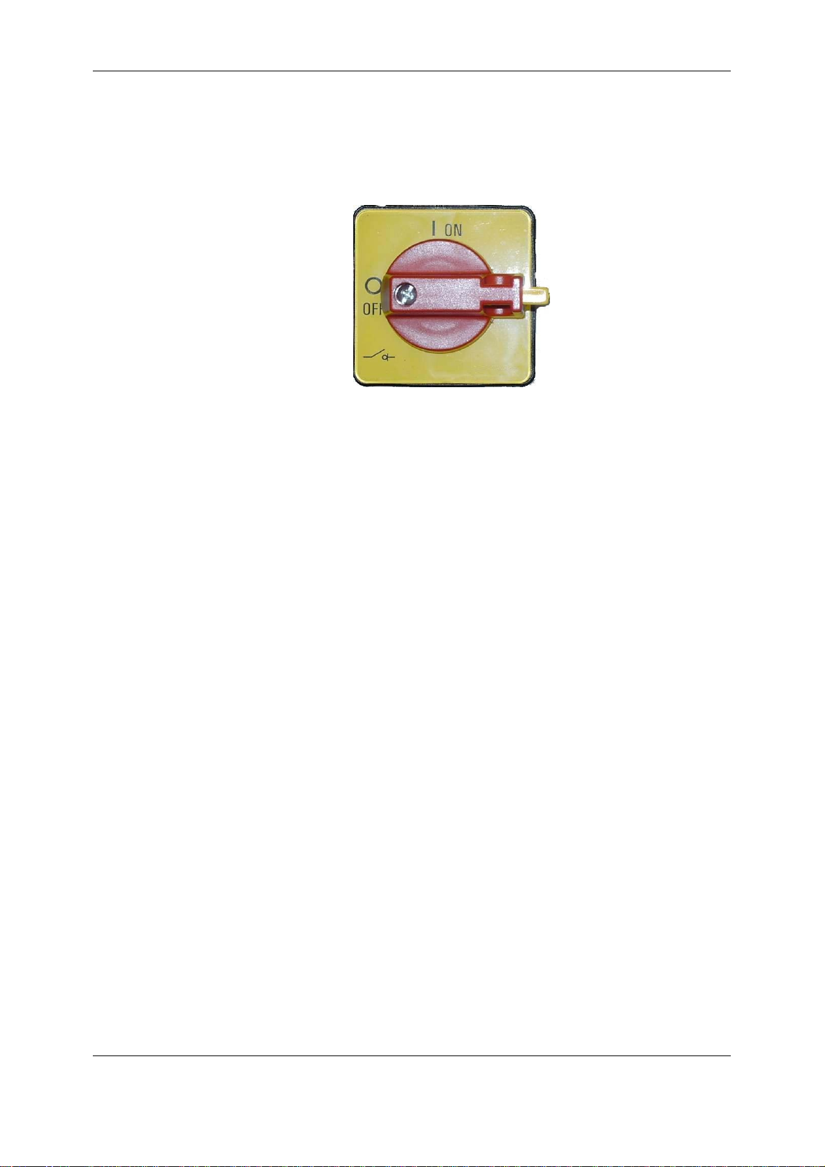
How to behave in case of emergency
In the event of an emergency, rotate the main and E-STOP switch 90° to the left in
order to shut down the entire system. The entire system is then voltage-free downstream from this switch.
Normal pressure is restored to the vacuum chamber after about 1 minute.
Packing, Transportation
Unpacking the FAM
The FAM is inspected for leaks and proper functioning at the factory, then carefully
packed for shipment. The connectors/ports are closed off so that no contamination
can enter the unit while it is in transit.
When receiving and unpacking the unit check it for damage in transit. Report any
damage to the forwarding agent immediately.
The packaging material should be re-used/re-cycled as appropriate for your area.
Transporting the FAM
The unit must be evacuated completely and the inlets and outlets must be closed
before transport.
Suction and pressure hoses and connection cables are coiled on the holders provided for that purpose and fastened in place.
HYDAC Filtertechnik GmbH
BEWA FAM10 3417360 en.doc 2008-06-06
en
Page 15 / 80
Page 16

FluidAqua Mobil – FAM 10/15 +CS1000 +AS1000 Packing, Transportation
Moving the FAM
CAUTION
High empty weight
(≈ 400 … 850 kg, depending on the version)
A minimum of 2 persons is required for
transport.
The FAM can be moved manually by pushing thanks to two steerable castors and
two fixed castors for heavy loads. The grips for pushing on the frame of the FAM are
to be used for this purpose in all cases without exceptions. The immobilization
brakes on the steerable castors are to be released prior to transport and then fixed
again in place after it has been completed.
None of the components should ever be used as grips for pushing or pulling the
FAM, because this will cause damage to it.
Fork lift
If the FAM is moved with a forklift, then this may only be used in conjunction with the
forklift eyes located on the device.
Crane
If the FAM is moved with a crane, then this may only be used in conjunction with the
crane eyes or the forklift eyes located on the device and with suitable hitching materials.
Train/truck
During transport, the FAMs that have castors must be placed that on supports that
are high enough to ensure that there is no load on the castors.
HYDAC Filtertechnik GmbH
BEWA FAM10 3417360 en.doc 2008-06-06
en
Page 16 / 80
Page 17
FluidAqua Mobil – FAM 10/15 +CS1000 +AS1000 Scope of Delivery
Scope of Delivery
Upon receiving the FAM check it for any damage in transit. The FAM may not be set
up and installed unless it is in perfect order. Any damage in transit is to be reported
to the forwarding agent or the department in charge immediately; the unit may not
be commissioned until this damage is properly remedied.
The following items are supplied:
Qty Description
1
FluidAqua Mobil FAM, ready for connection with suction and pressure hose
1 Tool, square 6 mm for switch box
1 Operating and maintenance instructions FAM
1 Operating and maintenance instructions Busch vacuum pump
1 Supplementary operating instructions (depending on FAM design)
HYDAC Filtertechnik GmbH
BEWA FAM10 3417360 en.doc 2008-06-06
en
Page 17 / 80
Page 18

FluidAqua Mobil – FAM 10/15 +CS1000 +AS1000 FAM Description
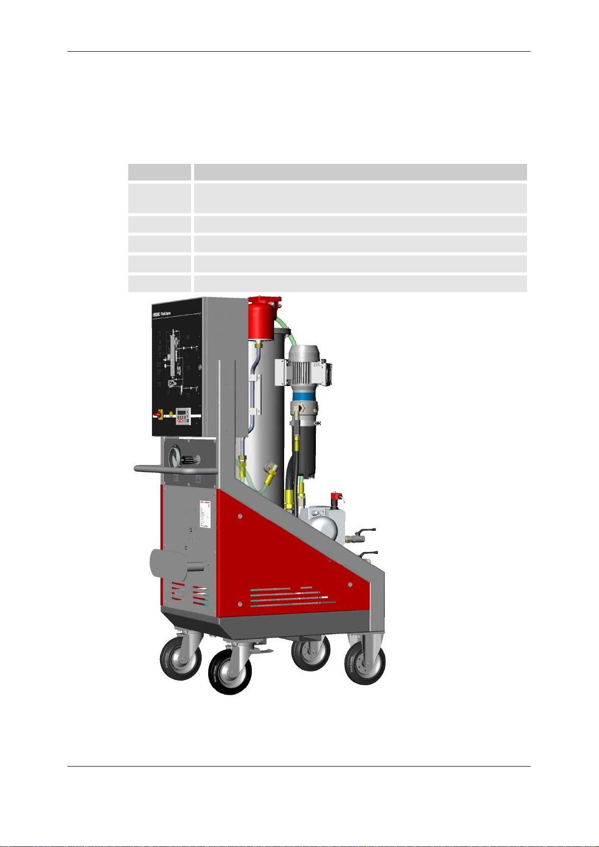
FAM Description
The FluidAqua Mobil FAM was developed for the dewatering, filtration and degassing of hydraulic and lubricating oils. It removes free water, emulsified water and
a large percentage of the water to be found in solution. The fluid filter that is installed
provides efficient filtering-out of solid materials.
The degassing of the medium is achieved by the vacuum set up in the vacuum container.
HYDAC Filtertechnik GmbH
BEWA FAM10 3417360 en.doc 2008-06-06
en
Page 18 / 80
Page 19
FluidAqua Mobil – FAM 10/15 +CS1000 +AS1000 FAM Description
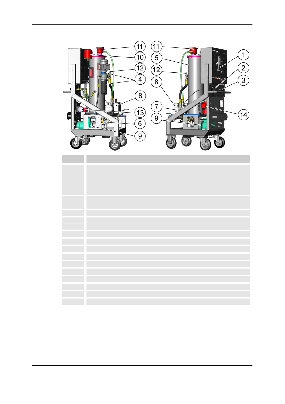
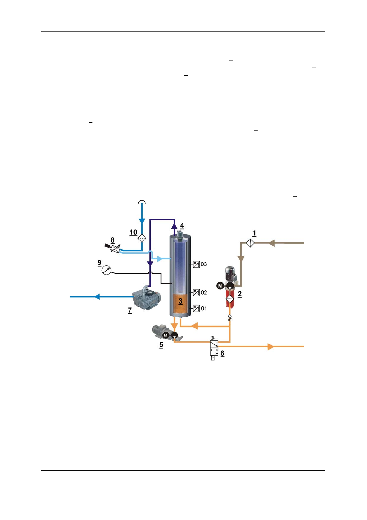
FAM components
Item Description
1 control cabinet with control panel consisting of:
2 Regulating valve to regulate the necessary vacuum in the vacuum
3 Vacuum gauge
4 Motor pump unit with fluid filter for the separation of solid particles
5 Vacuum chamber
6 3/2-directional control valve
7 Suction strainer
8 Vacuum pump
9 Evacuation pump
10 Air filter and dryer
11 Heater mounted in vacuum chamber (Option)
12 AS1000 (Optional)
13 CS1000 (Optional)
14 Motor-pump assembly for CS1000 (Optional)
- main switch
- alarm signal lamp
- control panel with display
- component diagram
chamber
(OLF-5)
HYDAC Filtertechnik GmbH
BEWA FAM10 3417360 en.doc 2008-06-06
en
Page 19 / 80
Page 20
FluidAqua Mobil – FAM 10/15 +CS1000 +AS1000 FAM Description
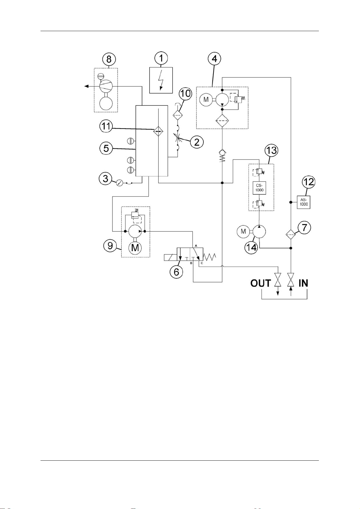
Hydraulic schematic
HYDAC Filtertechnik GmbH
BEWA FAM10 3417360 en.doc 2008-06-06
en
Page 20 / 80
Page 21
FluidAqua Mobil – FAM 10/15 +CS1000 +AS1000 FAM Description
Technical specifications
The FAM is able to dewater authorized fluids down to a water content of less than
100 PPM.
FAM 10/10 ≈ 0.8 l/h
FAM 10/15 ≈ 1.0 l/h
The dewatering speed is dependent on:
Water content
Fluid temperature
Detergent additives
Volumetric flow of the FAM
The fluid temperature must be at least 40°C in order to ensure an effective water
separation speed.
The sample for the determination of the water content must be extracted from the
system to be cleaned during operation.
Typical dewatering rates:
Dewatering rate
Free water on the floor of the tank influences the overall water content. This is to be
drained before starting.
Suitable Fluids
The FAM may only be used only in connection with lubrication and mineral oils
or with mineral oil-based media or with biological fluids that can be broken down
quickly - on the basis of synthetic esters (HEES).
Please contact us if you want to use other fluids.
Operation with other media could destroy the FAM.
The FluidAqua Mobil can only be utilised in connection with the following hydraulic
fluids:
Mineral oils acc. DIN 50524
Gear oils acc. DIN 51517 and DIN 51524
NOTE
Synthetic esters (HEES) acc. to DIN 51524/2
HYDAC Filtertechnik GmbH
BEWA FAM10 3417360 en.doc 2008-06-06
en
Page 21 / 80
Page 22
FluidAqua Mobil – FAM 10/15 +CS1000 +AS1000 FAM Description
FAM Function description
After the FAM has been switched on, filter pump unit 1 begins to suction fluid out of
the tank to be cleaned out and to pump it through the filter into vacuum chamber 3
at a speed of 10 l/min. Vacuum pump 7
begins at the same time to build up the necessary vacuum. The fluid to be cleaned trickles downward through special filling materials. These filling materials are responsible for forming a thing fluid film and reducing the speed of the trickle. At the same time, a stream of air flowing upward from
below against this current takes up the fluid and conveys the to the outside by
means of the vacuum pump. Once level 02 is reached on the level switch, emptying
pump 5
level falls until level 01 is reached, after which solenoid valve 6
is switched on in order to convey around 15 l/min to the outlet. The filling
switches on and the
two pumps convey into the vacuum chamber. The filling level continues to rise until
level 02 is reached, after which the solenoid valve shuts back off again, the filling
level falls again, etc.
After actuating the stop switch, the filter-pump unit stops and the evacuation pump
empties the vacuum chamber.
Switching the main switch to "OFF" renders all engines and valves voltage-free.
The vacuum in the vacuum chamber is regulated with the regulating valve 8
.
Possible Applications
The electric control supports several operation modes e.g.,
• the FAM is switched On/Off at a control room.
• the general malfunction message can be transmitted to a control room
• the operating status can be queried
• the FAM can be switched on/off by a level sensor in the transfer by pumping
operation mode.
HYDAC Filtertechnik GmbH
BEWA FAM10 3417360 en.doc 2008-06-06
en
Page 22 / 80
Page 23
FluidAqua Mobil – FAM 10/15 +CS1000 +AS1000 FAM Description
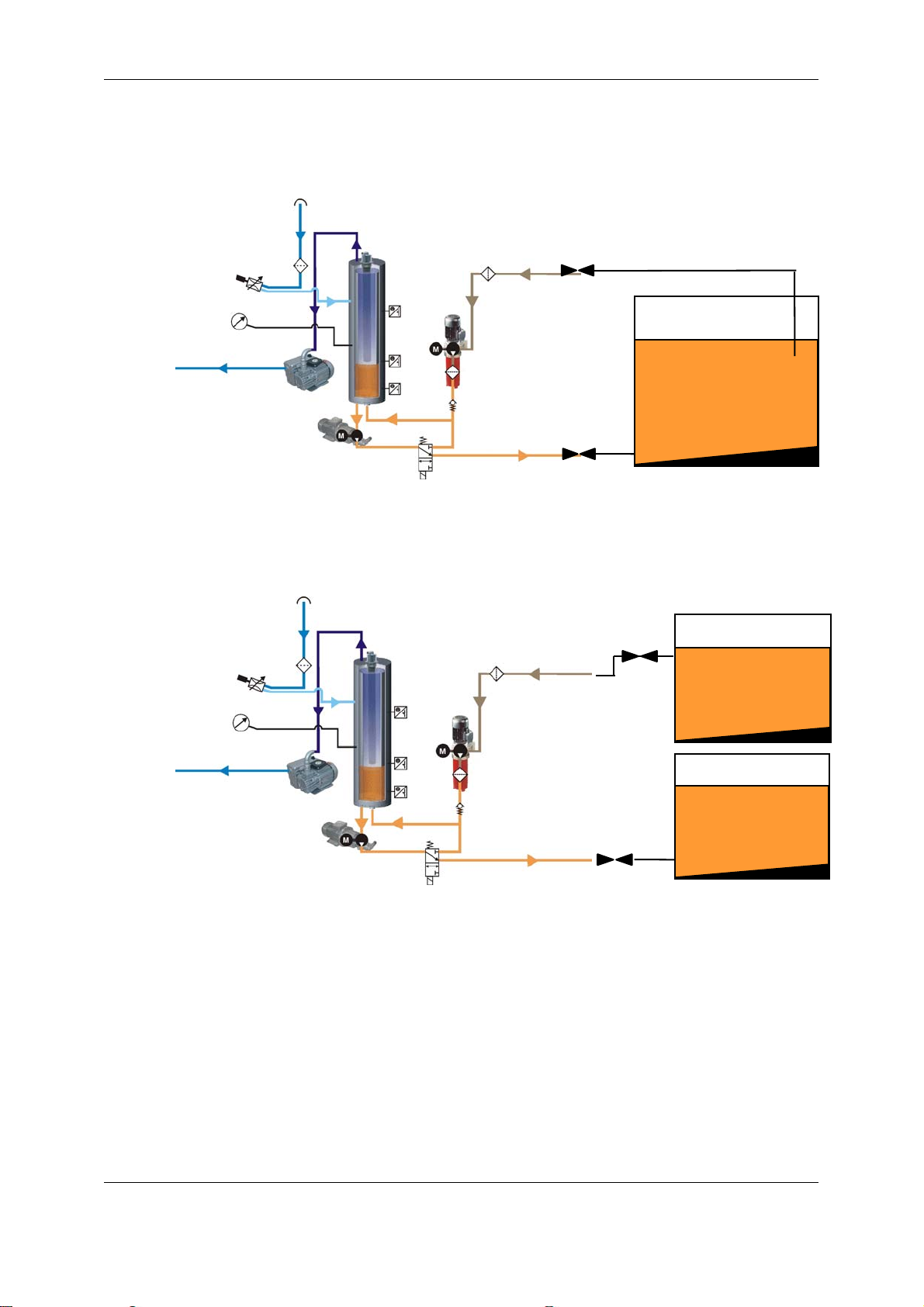
Better cleaning results can be obtained through permanent operation of the FAM in
bypass flow.
Bypass purification (dewatering, filtration and degassing).
The FAM is connected with suction and pressure lines to the tank and cleans the
medium in continuous operation.
Transfer by pumping (dewatering, filtration and degassing)
The FAM is connected to a contaminated oil tank by means of a suction line and
pumps the fluid into the clean oil tank.
The filling level in the clean oil tank must be monitored permanently during this operating mode in order to exclude the possibility of overfilling.
Contaminated
oil
Clean oil
HYDAC Filtertechnik GmbH
BEWA FAM10 3417360 en.doc 2008-06-06
en
Page 23 / 80
Page 24

FluidAqua Mobil – FAM 10/15 +CS1000 +AS1000 FAM Set-up and Connection
FAM Set-up and Connection
Setting up the FAM
The following points are to be observed when setting up the FAM:
• The unit has to be set up in a horizontal position on a level surface.
Special mounting is not required.
• The immobilization brakes on the wheels must be locked to avoid unintended
movement of the unit.
• Place the FAM near the tank to be cleaned (length of the hoses max. 5 m, height
difference max. 2 m).
• The ambient temperature may not be below 10°C and may not exceed 40°C.
• Access to the main switch has to be unimpeded at all times.
• An area of at least 0.8 m must be kept free for maintenance purposes on both
the left hand and right hand sides of the FAM.
Hydraulic Connection of the FAM
Connecting the suction port connection (IN)
Make the suction-side connection with a flexible hose that is resistant to negative
pressure or with pipelines. The nominal size of the connecting lines must be at least
as large as the cross-section of the unit in order to prevent excessively high pressure loss.
Permissible suction pressure: -0.3 to 1 bar.
Connection to the tank must be done in a manner so that it is always below the oil
level.
NOTE
The medium may not be suctioned directly from the bottom of the tank.
The greatest amount of impurities in the fluid is to be found at the bottom of
the tank.
High levels of contamination in the fluid can cause damage to the FAM.
Connecting the return port connection (OUT)
The return-flow line or the return-flow hose must be installed below the level of the
oil in order to prevent air from entering the medium.
HYDAC Filtertechnik GmbH
BEWA FAM10 3417360 en.doc 2008-06-06
en
Page 24 / 80
Page 25

FluidAqua Mobil – FAM 10/15 +CS1000 +AS1000 FAM Set-up and Connection
Preparing the Vacuum Pump
As a basic rule, the rotary vane vacuum pump is not filled with oil at the time the
FAM is delivered.
NOTE
Operating the FAM without oil in the vacuum pump will cause irreparable
damage to the pump.
The rotary vane vacuum pump must be checked for sufficient filling be-
fore commissioning.
To fill the rotary vane vacuum pump, the
oil is filled in through the filling screw plug
(1) until the oil filling has risen above the
MIN marking in the viewing glass (2).
Exceeding the MAX marking will lead to
fault messages on the control panel.
1
2
The oil quantity between the MIN/MAX markings is ≈ 0.3 liters
The water level is monitored automatically by the integrated float switch while the
FAM is in operation. A message will appear on the control panel when the MIN filling
level has been reached.
Synthetic vacuum pump oil in accordance with DIN 51506, Group VDL, ISO VG100
must be used for topping up.
This can be ordered from HYDAC under the part. no.:
Description Part no.:
Vacuum pump oil VE101
DIN 51506, Group VDL, ISO VG100, synthetic
1 liters 06018128
Vacuum pump oil VE101
DIN 51506, Group VDL, ISO VG100, synthetic
HYDAC Filtertechnik GmbH
BEWA FAM10 3417360 en.doc 2008-06-06
en
5 liters 06018129
Page 25 / 80
Page 26

FluidAqua Mobil – FAM 10/15 +CS1000 +AS1000 FAM Set-up and Connection
Checking the settings on the heater (optional)
If the FAM-is equipped with an internal heater, the temperature can now be set to
the desired value.
For this, the upper cover of the heater must be opened with appropriate equipment
and the desired operating temperature set. (The working temperature is preset to
55°C; if 80°C is exceeded, then the safety thermostat will shut the device off.)
(A) Fluid temperature 55°C
(B) Safety thermostat 80°C
HYDAC Filtertechnik GmbH
BEWA FAM10 3417360 en.doc 2008-06-06
en
Page 26 / 80
Page 27

FluidAqua Mobil – FAM 10/15 +CS1000 +AS1000 FAM Set-up and Connection
Electrical Connection of the FAM
DANGER
Electric shock
Any work involving the electrical system may
only be done by a properly trained, certified
electrician.
The voltage and frequency indicated on the rating plate must coincide with the voltage supply present.
If a plug is present on the FAM or if a plug is mounted, then the FAM is to be operated from a correspondingly fused socket.
The direction of rotation of the motor is checked by means of a phase sequence relay. If the phase sequence at the socket is recognized as being incorrect, then a
message will appear on the display.
Any reversal of the direction of rotation that may be
required is accomplished by switching two phases in
the terminal box of the engine or, in the event that the
device is equipped with an electric plug with phase
switcher, by rotating two phases in the plug. No dismantling of the plug is required.
HYDAC Filtertechnik GmbH
BEWA FAM10 3417360 en.doc 2008-06-06
en
Page 27 / 80
Page 28

FluidAqua Mobil – FAM 10/15 +CS1000 +AS1000 Starting up the FAM
Starting up the FAM
Switching on the FAM
Move main switch to the "ON" position and wait until the "Fault" lamp lights up briefly
(lamp test) and the following message will appear in the display.
The most recently selected operating mode will be shown in the display.
Operating mode: Dewater + Filter
Ready for operation, please press Start
START
F1
Press "START" key. The system now begins with the starting phase:
• The vacuum pump starts up, the feed pump conveys and the vacuum column is
filled.
• The controller switches to the RH+P Menu
• The evacuation pump is started up and the starting period is finished when the
vacuum chamber is filled to the MAX filling level.
• The FAM controller switches over to automatic operation.
Now regulate the vacuum pressure with the regulating valve on the right of the vacuum gauge depending upon the operating viscosity:
Operating viscosity Vacuum pressure (absolute pressure)
50 mm2/s Hydraulic oil 300 mbar / 30 kPa
F2
F3
MENU1
F4
F1 = Start FAM
F2 = Stop
F3 = Reset (after malfunction)
F4 = Switch to MENU1
300 mm2/s Lubrication oil 400 mbar / 40 kPa
50 mm2/s Ester oil 400 mbar / 40 kPa
If a foaming of the medium is noticed in the standpipe, then increase the pressure
by 50 ... 100 mbar (e.g. from 300 mbar to 400 mbar).
The FAM will not start up again automatically when voltage is restored after a voltage failure; it must be restarted instead.
HYDAC Filtertechnik GmbH
BEWA FAM10 3417360 en.doc 2008-06-06
en
Page 28 / 80
Page 29

FluidAqua Mobil – FAM 10/15 +CS1000 +AS1000 Starting up the FAM
Shutting off the FAM
Operating mode: Dewater + Filter
Automatic mode
STOP
MENU1
F1 = Start FAM
F1
F2
F3
F4
F2 = Stop
F3 = Reset (after malfunction)
F4 = Switch to MENU1
Press the "STOP" key. Now the unit starts the run-down phase:
• the vacuum pump and all filling pumps are switched off.
Exception: When the heater is switched on, a 60-second cooling phase intervenes during which only the heater is switched off.
It is not until this has run its course that the filling pumps are switched off. The
respective current operating status will be shown in the display.
• The evacuation pump runs until the vacuum column is empty.
The run-down phase status is shown in the display
• If the main screen from Section 0 appears on the display, then the after-running
phase has been completed and the FAM is ready for operation again.
• Now the FAM can be switched off via the main switch.
HYDAC Filtertechnik GmbH
BEWA FAM10 3417360 en.doc 2008-06-06
en
Page 29 / 80
Page 30

FluidAqua Mobil – FAM 10/15 +CS1000 +AS1000 Starting up the FAM
Control Panel - SIMATIC PANEL
INSDEL
TAB
HELP
ESC
+/-
F1
F2
F3
F4
SHIFT
ACK
ENTER
Unintended actions could be triggered if several keys are pushed at once.
Caution
Unintended actions
Pressing more than two keys at once during the "Online" operating
mode could lead to unintended actions in the system.
Never press more than two keys simultaneously
Operating the FAM from the Control Panel
Only those buttons are described below whose operation may be required.
The selected operating mode is shown in the upper line, the middle line shows the
current operating status, and the key assignment is displayed in the lower line.
Operating mode: Dewater + Filter
Ready for operation, please press Start
MENU1
F4
START
F1
F2
F3
-> Mode
-> Operating status
-> Key assignment
-> Function keys
HYDAC Filtertechnik GmbH
BEWA FAM10 3417360 en.doc 2008-06-06
en
Page 30 / 80
Page 31

FluidAqua Mobil – FAM 10/15 +CS1000 +AS1000 Starting up the FAM
Start screen
Operating mode: Dewater + Filter
Ready for operation, please press Start
START
MENU1
F1 = Start FAM
F1
F2
F3
F4
F2 = Stop
F3 = Reset (after malfunction)
F4 = Switch to MENU1
START = Is displayed only in the operating status "Ready for op-
eration".
After this key has been pressed, the current operating
status on the display switches to "Starting phase" and
the "RF+D" screen appears.
STOP = Is shown during the starting phase and during automatic
operation.
RESET = Is displayed only when there is a fault
The most recently selected operating mode will always be shown in the start screen.
HYDAC Filtertechnik GmbH
BEWA FAM10 3417360 en.doc 2008-06-06
en
Page 31 / 80
Page 32

FluidAqua Mobil – FAM 10/15 +CS1000 +AS1000 Starting up the FAM
Menu1
Start
image
OM
F1
Measured values:
RH
MAN.
F2
LANGUAGE
F3
Cont.
MENU1
MENU2
F4
F1 = Select operating mode
2 = Switch on manual operation
F3 = Change languages
F4 = Switch to MENU2
INS
or by means of
The buttons illustrated can be selected with the keys
+
TAB
, which is marked by framing made up of a line of
SHIFT
the key combination
DEL
dashes.
The changeover to the selected menu is achieved with the key
Start
= Back to the start screen
.
screen
RH = "Relative humidity" menu screen
Menu2
Cont. = "Contamination" menu screen
MENU2
INTER-
F1
OHM
F2
CONFIG.
F3
MENU1
F4
F1 = INTERVALS
F2 = Operating hours meter
F3 = CONFIGURATION
F4 = Switch to MENU1
INTERVALS
= Times for the recurrent inspection interval for the "Cleaning until"
and/or "Dewatering to" operating mode
OHM = Display operating hours meter
CONFIG. = FAM Configuration – Access password-protected
(For HYDAC Service only)
MENU1 = Switch to MENU1
HYDAC Filtertechnik GmbH
BEWA FAM10 3417360 en.doc 2008-06-06
en
Page 32 / 80
Page 33

FluidAqua Mobil – FAM 10/15 +CS1000 +AS1000 Starting up the FAM
Operating Mode (OM)
Operating mode: Dewater + Filter
F1 = EW+FT
DW+FT
DWT+
FT
EW+H
+FT
NEXT
F2 = DWT+FT
F3 = EW+H+FT
F1
F2
F3
F4
F4 = CONTINUE
= Switch to MENU1
DW+FT = Dewatering + Filtration
DWT+FT = Dewatering until + Filtration
EW+H+FT = Dewatering + Heating + Filtration
NEXT = Other operating modes
Only operating modes that can be selected are displayed.
A change of operating modes is possible at any time during the automatic operation
of the ready for operation status. Operating modes are active as soon as they are
selected.
Operating mode: Dewater + Filter
F1 = DWT+H+FT
DWT+
H+FT
FT
FT+H
NEXT
F2 = FT
F3 = FT+H
F1
F2
F3
F4
F4 = CONTINUE
= Switch to MENU1
DWT+H+FT = Dewatering until + Heating + Filtration
FT = Filtration only
FT+H = Filtration + Heating
NEXT = Other operating modes
HYDAC Filtertechnik GmbH
BEWA FAM10 3417360 en.doc 2008-06-06
en
Page 33 / 80
Page 34

FluidAqua Mobil – FAM 10/15 +CS1000 +AS1000 Starting up the FAM
Operating mode: Dewater + Filter
EW+
FTB
F1
EW+FTB = Dewatering + Filtration until
EW+H+FTB = Dewatering + Heating + Filtration until
FTT = Filtration until
NEXT = Other operating modes
Operating mode: Dewater + Filter
FTT+
H
F1
DW+H
+FTT
F2
F2
F3
F3
FTT
NEXT
F4
MENU1
F4
F1 = EW+FTB
F2 = EW+H+FTB
F3 = FTB
F4 = CONTINUE
= Switch to MENU1
FTT+H = Filtration until + Heating
MENU1 = Back to MENU1
Manual Menu (MANUAL)
OPERA-
TOR
F1
OPERATOR = Manual operation for operator
SERVICE = Manual operation for HYDAC Service (password-protected)
SERVICE
F2
F3
Selection
Manual
MENU1
F4
F1 = FTB+H
F4 = Switch to MENU1
F1 = OPERATOR
F2 = SERVICE
F4 = MENU1
MENU1 = Back to MENU1
HYDAC Filtertechnik GmbH
BEWA FAM10 3417360 en.doc 2008-06-06
en
Page 34 / 80
Page 35

FluidAqua Mobil – FAM 10/15 +CS1000 +AS1000 Starting up the FAM
OPERATOR (MANUAL1)
Manual
operation
ON
F1
Manual Operation
FP = Switch filling pump On/Off
DP = Switch evacuation pump On/Off
The ON/OFF operating status of each component is shown on the display.
FP
OFF
F2
= Switching manual operation on/off
The ON displayed below Manual operation indicates that
manual operation is switched on.
If individual components are switched on beforehand, then
these components can now all be switched On or Off vai
manual operation F1.
DP
OFF
F3
Manual1
Back
NEXT
F4
F1 = Manual operation
F2 = FP (Filling pump)
F3 = EP (Evacuation pump)
F4 = CONTINUE in Manual2
Menu
= return to the screen "Se-
lection manual operation"
Components that are not installed will not be displayed.
OPERATOR (MANUAL2)
VP
OFF
F1
VP = Switching vacuum pump on/off
RV = Switching return valve on/off
RV
OFF
F2
F3
Manual2
Back
END
F4
F1 = VP (Vacuum pump)
F2 = RV (return valve)
F4 = END
= back to "Manual1" Menu
HYDAC Filtertechnik GmbH
BEWA FAM10 3417360 en.doc 2008-06-06
en
Page 35 / 80
Page 36

FluidAqua Mobil – FAM 10/15 +CS1000 +AS1000 Starting up the FAM
LANGUAGE
Language selected:
SELECT
LAN-
F1
SELECT
LANGUAGE
Language
ENGLISH
MENU1
F2
F3
F4
F1 = Select language
F4 = back to "MENU1"
= Press the F1 key repeatedly until the desired language ap-
pears.
HYDAC Filtertechnik GmbH
BEWA FAM10 3417360 en.doc 2008-06-06
en
Page 36 / 80
Page 37

FluidAqua Mobil – FAM 10/15 +CS1000 +AS1000 Starting up the FAM
RH+P (Relative Humidity + Pressure)
Rel. humidity: Nominal: 30% Actual:
33%
°
Ready for operation. Please press Start
START
F1
STOP
F2
RESET
F3
MENU1
F4
START = Start FAM
is displayed only in the operating status "Ready for operation"
STOP = Stop FAM
is displayed only in the operating status "Starting phase" and
"Automatic operation"
RESET = Reset error messages
Is displayed only in the presence of faults
Display:
Rel. humidity: Nominal:
= The nominal value can be changed from 0 ... 99% (see
chapter 0).
RH
+P
F1 = START
F2 = STOP
F3 = RESET
F4 = back to "MENU1"
Factory setting: 30%
Rel. humidity: Actual: = Display of the current moisture at the FAM inlet.
A display of 0 ... 100% is possible.
Temp. = Medium temperature at inlet to the FAM.
HYDAC Filtertechnik GmbH
BEWA FAM10 3417360 en.doc 2008-06-06
en
Page 37 / 80
Page 38

FluidAqua Mobil – FAM 10/15 +CS1000 +AS1000 Starting up the FAM
Contamination (Selection Contamination)
Selection
ISO
YES
F1
ISO = Display cleanliness code in accordance with ISO
SAE = Display cleanliness code in accordance with SAE
SAE = Display cleanliness code in accordance with NAS
Only the cleanliness code marked with "YES" can be selected.
SAE
NO
F2
NAS
NO
F3
Contami-
nation
BACK
F4
F1 = ISO
F2 = SAE
F3 = NAS
F4 = back to "MENU1"
ISO
tgt:
av:
Ready for operation. Please press Start
18
20
START
F1
START = Start FAM
STOP = Stop FAM
RESET = Reset error messages
Display:
16
4µ
4µ
18
STOP RESET
F2
is displayed only in the operating status "Ready for operation"
is displayed only in the operating status "Starting phase" and
"Automatic operation"
Is displayed only in the presence of faults
6µ
6µ
F3
14
15
14µ
14µ
MENU1
F4
ISO
F1 = START
F2 = STOP
F3 = RESET
F4 = back to "MENU1"
ISO: Nominal: = The nominal value can be changed from 0 ... 25% (see
chapter 0).
ISO: Actual: = Display of the current contamination at the FAM inlet.
HYDAC Filtertechnik GmbH
BEWA FAM10 3417360 en.doc 2008-06-06
en
Page 38 / 80
Page 39

FluidAqua Mobil – FAM 10/15 +CS1000 +AS1000 Starting up the FAM
Intervals
Messwiederholintervall:
Intervals
3 Sollminuten
0 Abgelaufene Minuten
MENU2
F1
F2
F3
F4
F4 = back to "MENU2"
Display:
TRG MIN: = Recurrent measurement interval:
Adjustable from 2 – 360 minutes
Factory setting: 60 minutes
Elapsed minutes
= Display of the repeat testing interval minutes that have already
elapsed
HYDAC Filtertechnik GmbH
BEWA FAM10 3417360 en.doc 2008-06-06
en
Page 39 / 80
Page 40

FluidAqua Mobil – FAM 10/15 +CS1000 +AS1000 Starting up the FAM
an operating-hours counter, and
Operating hours
18 hours 43 minutes
MENU2
F1
F2
F3
Display:
Operating hours = Display of the FAM operating hours
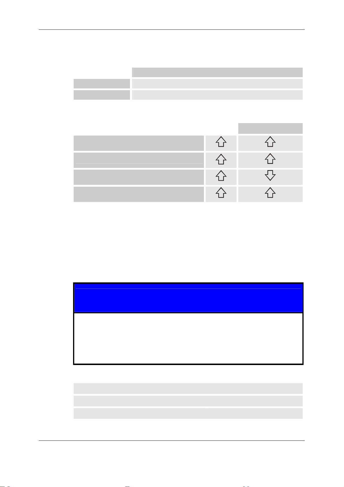
Operating Mode "Cleaning until"
The operating mode "Cleaning until" is possible only after a water saturation of
<90%. In cases of >90% or free water, the measurements of the ContaminationSensor will be falsified to such an extent that the CS will issue a fault message.
This fault message is ignored by the SPS. The most recently saved measured value
remains saved there until a restart is required.
The following message is output when the contamination is selected:
"Oil saturation >90%. Measurement with CS not possible!"
This display can be minimized by pressing the ESC key, so that the screen can be
exited again by selecting Menu1.
F4
F4 = back to "MENU2"
If a water saturation level of 90% occurs during automatic operation, then the operating mode switches automatically in accordance with the following table:
Selected operating mode: changes automatically after:
FTT => FT
EW+FTB => DW+FT
HYDAC Filtertechnik GmbH
BEWA FAM10 3417360 en.doc 2008-06-06
en
Page 40 / 80
Page 41

FluidAqua Mobil – FAM 10/15 +CS1000 +AS1000 Starting up the FAM
General Operating Instructions - SIEMENS PANEL
System Keys
The system keys are used for making entries on the operating device. Overview of
the control keys
Functioning Effect
Moving the cursor
,
,
INS
+/-
DEL
TAB
Activate field
TAB
SHIFT
+
SHIFT
Display Help text
HELP
+
ESC
SHIFT
The next field in horizontal direction is activated with
Fields.
The next field in vertical direction is activated with
Fields.
The next field is activated - in the sequence that has
been defined in the project (Tab sequence).
The second function of an additional system key is
enabled.
Displays a window with Help text for the selected object.
Pressing makes it possible to switch back and
forth between screen Help text and the object Help
text, i.e. for an EA field.
Cancel action
HELP
ESC
Acknowledge message
ACK
Undo
An entry can be undone as long as that entry has not
yet been confirmed with .
• Closing the message window – if present
• Cancelling the display of a Help text in order to return
to the previous display.
Acknowledges the currently displayed or highlighted
message or all messages of an acknowledgement
group - depending on the project planning.
Calling up the Edit mode – redirects the entry via
TAB
and
+/-
ends the Edit mode and confirms the
entry
Navigating in the list
HYDAC Filtertechnik GmbH
BEWA FAM10 3417360 en.doc 2008-06-06
en
Page 41 / 80
Page 42

FluidAqua Mobil – FAM 10/15 +CS1000 +AS1000 Starting up the FAM
Table 8-2 Keys for navigating in lists
Key Effect of actuation
Moving the cursor
TAB
or
Entries and Help
You enter values in the Entry fields. The values are transferred from the entry fields
to the controller.
Proceed as follows:
1. Select the desired entry field within the image.
Depending on the field type, you can enter values of the following type in the
entry field:
– Numerical
– Alphanumerical
– Symbolic
– Date/Time
2. Enter the value.
3. Confirm your entry with
Marks the previous or the following list entry
+/-
HELP
ESC
or cancel the entry with
.
Numerical Values
Numerical values are entered one character at a time via the system keyboard. If
has been pressed, then you can modify the value one character at a time with
the aid of the cursor keys.
If a field already contains a value, then this will be deleted completely from the field
SHIFT
by pressing
Alphanumerical Values
Alphanumerical values, numbers and letters are entered one character at a time via
the system keyboard. If
character at a time with the aid of the cursor keys.
If a field already contains a value, then this will be deleted completely from the field
SHIFT
by pressing
+
+
DEL
.
has been pressed, then you can modify the value one
DEL
.
The expanded character set is available in fields that have the "String" format.
Date and Time
Values for date and time are entered in accordance with the alphanumerical values.
HYDAC Filtertechnik GmbH
BEWA FAM10 3417360 en.doc 2008-06-06
en
Page 42 / 80
Page 43

FluidAqua Mobil – FAM 10/15 +CS1000 +AS1000 Starting up the FAM
Entering and Modifying Numerical and Alphanumerical Values
TAB
SHIFT
One entry field was activated with
+
or with the cursor keys.
Key Effect
Moving the cursor
DEL
or
INS
Marks the previous or the following list entry
Control buttons for entering characters
Functioning Effect
SHIFT
+
+/-
The algebraic sign of a numerical value is changed.
Pressing
tween the two signs.
TAB
,
+/-
All available characters from the expanded character
set will be called up one after the other.
The entry becomes valid
HELP
ESC
The entry is deleted
The original value becomes valid again.
SHIFT
+
+/-
switches back and forth be-
The following approaches are possible for entering numerical and alphanumerical
characters:
• Entering a value, which causes the existing value to be replaced completely
• Modifying the character of an existing value
HYDAC Filtertechnik GmbH
BEWA FAM10 3417360 en.doc 2008-06-06
en
Page 43 / 80
Page 44

FluidAqua Mobil – FAM 10/15 +CS1000 +AS1000 Starting up the FAM
Enter Value
If you wish to enter a new value - and not only a single character - then you can delete the entire contents of the field.
Proceed as follows:
DEL
SHIFT
1. Actuate
+
TAB
+/-
2. Enter value with
3. Press
The entry is confirmed. You can abort the entry with
Partial Value Changes
Proceed as follows:
1. Press
2. Select character to be changed with
3. Modify character with
4. Press
The entry is confirmed. You can abort the entry with
or with
HELP
ESC
.
TAB
or with
INS
or with
+/-
DEL
HELP
ESC
.
Character Call-up Sequence
When you enter a value in an alphanumerical field for the first time,
INS
The letter "A" will be called up after pressing
or
. This also applies when
a character is added to ones that have already been entered.
The following applies for further entries:
TAB
Press
when letters of the alphabet are to be entered.
All of the upper and lower case letters will be displayed first, and afterwards the
special characters and numerals.
+/-
Press
when characters are to be entered.
First a few special characters are displayed, and then the numerals.
HYDAC Filtertechnik GmbH
BEWA FAM10 3417360 en.doc 2008-06-06
en
Page 44 / 80
Page 45

FluidAqua Mobil – FAM 10/15 +CS1000 +AS1000 Starting up the FAM
If a value has already been entered, then the next following value will be displayed
TAB
+/-
with
or with
.
Example for numeric entry
To enter "–12.34", activate the entry field. Hold one of the cursor keys
+/-
with
pressed down for as long as it takes for the desired character to appear.
Press the following keys:
+00.00
5x
DEL
+00.00
+/-
-00.00
INS
-00.00
TAB
-10.00
TAB
or
INS
-10.00
TAB
-12.00
2x
INS
-12.00
TAB
-12.30
INS
-12.30
TAB
-12.34
-12.34
You can begin the entry at any given position in the entry field. The
algebraic sign can also be modified during the entry at any position in the entry field
+/-
SHIFT
with
+
HYDAC Filtertechnik GmbH
BEWA FAM10 3417360 en.doc 2008-06-06
.
en
Page 45 / 80
Page 46

FluidAqua Mobil – FAM 10/15 +CS1000 +AS1000 Starting up the FAM
Entering and Changing Date and Time
TAB
SHIFT
A Date/Time field was activated with
+
or with the cursor keys.
Entering date and time
Use numerical and alphanumerical characters for entering date and time.
Safety Queries
The manual operation of the FAM is protected by a safety system.
If you are operating one operating object with password protection in the project,
then you must first register on the operating device.
A registration dialog is displayed for this purpose in which you enter a password.
User:
Password:
OK
F1
F2
Admin
F3
Cancel
F4
Registration dialog
You enter the password in the "Password" field in the registration dialog.
Proceed as follows:
1. Press
2. Hold one of the keys
+
TAB
pressed down for as long as it takes for
SHIFT
the desired character to appear.
INS
3. If you need additional characters, press
TAB
or with
+/-
4. If the password is complete, activate the "OK" button with
press
. You can abort the process with "Cancel".
and select the character with
TAB
SHIFT
+
and
After logging in, you can operate the operating objects that have password protection.
HYDAC Filtertechnik GmbH
BEWA FAM10 3417360 en.doc 2008-06-06
en
Page 46 / 80
Page 47

FluidAqua Mobil – FAM 10/15 +CS1000 +AS1000 Starting up the FAM
Once you log out, you can no longer operate the objects that have password protection, but instead you must also register yourself once again as necessary.
Sign-off time
A log-out time is entered in the system for the user. The user is automatically logged
out if the time that elapses between any two given actions on the part of the user,
e.g. entering a value or changing screens, is longer than the log-out time. He will
then have to log in again in order to operate objects under password protection.
Password
The password and the log-out time are encoded in a list and stored on the operating
device in a manner that is not affected by network power outages.
HYDAC Filtertechnik GmbH
BEWA FAM10 3417360 en.doc 2008-06-06
en
Page 47 / 80
Page 48

FluidAqua Mobil – FAM 10/15 +CS1000 +AS1000 Error messages
Error messages
NOTE
The switch cabinet door may not be opened unless the main switch is at "Off", because otherwise the main switch would be damaged.
The fault messages are not displayed in all of the menus but rather only in the following screens:
- Start screen
- RH
- CS
The fault messages that are relevant to the CS will only be displayed on the CS
screen.
The device comes to a stop and the fault indicator lamp flashes when fault messages occur. The device can not be started any more.
The operator can however jump into the different menus and operate a component
in the Manual Menu necessary for the elimination of the fault.
If several errors occur, then the most recently occurring message will be displayed
first. One can used the arrow keys to scroll through the individual fault messages.
In order to restart the device, first the error must be eliminated and then acknowledged afterwards. It is only then that automatic operation is possible again.
HYDAC Filtertechnik GmbH
BEWA FAM10 3417360 en.doc 2008-06-06
en
Page 48 / 80
Page 49

FluidAqua Mobil – FAM 10/15 +CS1000 +AS1000 Error messages
Displayed
Cause Remedy see
fault message
CS1xxx + CS conveyor
pump switched Off,
CS1xxx malfunction.
Start 10 new attempts
with Reset!
10x errors on the CS in
sequence
acknowledge the first
time this occurs and
restart, inform Service
Department if this occurs again with a
week's time
flow at the FAM inlet
too low for 5 minutes
already. Please check
insufficient oil in the
vacuum column after
switch-on
check and open inlet
FAM inlet.
FAM outlet blocked. Min. is not reached
Error, float switch of
rotary vane vacuum
Float switch or cable
defective
Determine error and
replace defective part
pump at fill level Min/fill
level Overflow.
Error, float switch of
vacuum tower at fill
Float switch or cable
defective
Determine error and
replace defective part
level Min. and/or fill
level Max.
Error, float switch of
water ring vacuum
Float switch or cable
defective
Determine error and
replace defective part
pump at fill level Min/fill
level Overflow.
Cable break, AS 1000
temperature
Cable break, AS 1000
water content
Cable break or AS is
defective
Cable break or AS is
defective
Cable break, CS. Cable break or CS is
defective
No defined value from
CS.
For details, see Operating and Maintenance
Instructions for the
ContaminationSensor.
No measured value
from CS. Check flow.
For details, see Operating and Maintenance
Instructions for the
ContaminationSensor.
Malfunction CS flow too
low.
For details, see Operating and Maintenance
Instructions for the
ContaminationSensor.
Fault, CS device error For details, see Operat-
Determine error and
replace defective part
Determine error and
replace defective part
Determine error and
replace defective part
For details, see Operat-
ing and Maintenance
Instructions for the
ContaminationSensor.
For details, see Operat-
ing and Maintenance
Instructions for the
ContaminationSensor.
For details, see Operat-
ing and Maintenance
Instructions for the
ContaminationSensor.
For details, see Operat-
HYDAC Filtertechnik GmbH
BEWA FAM10 3417360 en.doc 2008-06-06
en
Page 49 / 80
Page 50

FluidAqua Mobil – FAM 10/15 +CS1000 +AS1000 Error messages
Displayed
Cause Remedy see
fault message
Motor protection switch
Q2, drain pump,
tripped.
Motor protection switch
Q3, vacuum pump,
tripped.
Motor protection switch
Q4, filling pump,
tripped.
Motor protection switch
Q5, CS pump, tripped.
Oil filter contaminated.
Please replace oil filter.
Instructions for the
ContaminationSensor.
Electric motor of
evacuation pump overloaded
Electric motor of vacuum pump overloaded
Electric motor of filling
pump overloaded
Electric motor of CS
pump overloaded
Maximum differential
pressure at the filter
reached
Instructions for the
ContaminationSensor.
Switch on engine pro-
tection in the electric
control, check operat-
ing viscosity
Drain the fluid in the
tank, clean the tank,
refill
Switch on engine pro-
tection in the electric
control, check operat-
ing viscosity
Switch on engine pro-
tection in the electric
control, check operat-
ing viscosity
Changing the Filter
Element
0
Oil tank of rotary vane
vacuum pump empty.
Top up oil.
Oil tank of rotary vane
vacuum pump too full.
Please drain off oil.
Heater safety thermostat triggered.
Oil level in the tank of
the rotary vane vacuum
pump too low
Oil level in the tank of
the rotary vane vacuum
pump too high
Oil temperature heater
too large, oil diffusion
too low through the
heater
Top up oil
Open ball faucet and
drain oil
Reset thermostat in the
head of the heater.
Remove the cover of
the heater to do so.
Check filling pump for
proper functioning
Fuse element, heater Fuse has tripped Call in an electrician
Supply voltage to FAM:
wrong phase sequence. Change phase
incorrect phase sequence or phase sequence relay defective
Call in an electrician
sequence.
Dry-running Evacuation
Pump.
too little medium is being pumped into the
vacuum column
check suction filter and
clean it if necessary,
check filling pump for
proper functioning,
check viscosity
Vacuum chamber over- Emergency Off Max Check pressure in vac-
HYDAC Filtertechnik GmbH
BEWA FAM10 3417360 en.doc 2008-06-06
en
Page 50 / 80
Page 51

FluidAqua Mobil – FAM 10/15 +CS1000 +AS1000 Error messages
Displayed
Cause Remedy see
fault message
flow. Please empty the
vacuum chamber and
determine the cause.
FAM tray too full. Drain
and seal leaky site of
FAM.
filling level exceeded,
possible foam formation, evacuation pump
cavitation
uum column, check
evacuation pump for
proper functioning, in-
crease pressure in the
vacuum column in the
event of foaming (e.g.
from 300 mbar abso-
lute to 400 mbar ab-
soute)
FAM oil pan too full Drain oil pan, check the
FAM for leaks
HYDAC Filtertechnik GmbH
BEWA FAM10 3417360 en.doc 2008-06-06
en
Page 51 / 80
Page 52

FluidAqua Mobil – FAM 10/15 +CS1000 +AS1000 Error messages
Vacuum Chamber Overflow
Message:
Vacuum chamber overflow. Please
empty the vacuum chamber and determine the cause.
Press ESC key,
Select Menu 1 with F4 key
Press F2 key in "Menu 1" Select Manual Operation
Press F1 key in "Select Manual Operation" menu
"Manual 1"
F3 key in the "Hand 1" Menu Evacuation
pump is started
The vacuum column can
be evacuated from the
Emergency Stop Maximum level to the Minimum
Y
The pressure in the vacuum
column is too low
Raise pressure (e.g.
from 300 mbar to 400
mbar).
No
Evacuation pump not
conveying
check
HYDAC Filtertechnik GmbH
BEWA FAM10 3417360 en.doc 2008-06-06
en
Page 52 / 80
Page 53

FluidAqua Mobil – FAM 10/15 +CS1000 +AS1000 Error messages
FAM tray too full
Message:
FAM tray too full. Drain and seal leaky
site of FAM.
Empty the oil drip pan
Actuate ESC key and reset malfunction with the F3 key
Carry out check for leakage and eliminate leaks
if present.
Restart FAM with the F1 key.
Fault appears
again
Y
Check float switch and supply lines
No
Failure repaired
HYDAC Filtertechnik GmbH
BEWA FAM10 3417360 en.doc 2008-06-06
en
Page 53 / 80
Page 54

FluidAqua Mobil – FAM 10/15 +CS1000 +AS1000 Error messages
FAM outlet blocked
Message:
FAM outlet blocked. See Troubleshooting for BeWa.
Check locking features in the return-flow line. Open if
blocked.
Actuate ESC key and reset malfunction with the
F3 key.
Restart FAM with the F1 key
Fault appears
again
Y
Check evacuation pump for
proper functioning
Check return valve
Check filter
No
Failure repaired
HYDAC Filtertechnik GmbH
BEWA FAM10 3417360 en.doc 2008-06-06
en
Page 54 / 80
Page 55

FluidAqua Mobil – FAM 10/15 +CS1000 +AS1000 Error messages
FAM entry blocked
Message:
FAM entry blocked. See Troubleshooting
for BeWa.
Check locking features in the suction line. Open
if blocked.
Actuate ESC key and reset malfunction with the
F3 key.
Restart FAM with the F1 key
Fault appears
again
Y
Clean suction filter
Check hose between suction filter and filling pump
Check filling pump for
proper functioning
No
Failure repaired
HYDAC Filtertechnik GmbH
BEWA FAM10 3417360 en.doc 2008-06-06
en
Page 55 / 80
Page 56

FluidAqua Mobil – FAM 10/15 +CS1000 +AS1000 Error messages
Dry-running Evacuation Pump
Message:
Dry-running evacuation pump. See
Troubleshooting for BeWa.
Check locking features in the suction line. Open
if blocked.
Actuate ESC key and reset malfunction with the
F3 key.
Restart FAM with the F1 key
Fault appears
No
again
Y
Clean suction filter
Failure repaired
Check hose between suction filter and filling pump
Check filling pump for
proper functioning
HYDAC Filtertechnik GmbH
BEWA FAM10 3417360 en.doc 2008-06-06
en
Page 56 / 80
Page 57

FluidAqua Mobil – FAM 10/15 +CS1000 +AS1000 Error messages
Dry run drain pump
Message:
Supply voltage to FAM: wrong phase
sequence. Change phase sequence.
Switch off FAM, pull out mains plug
Replacement of 2 phases on the mains plug, check mains volt-
Plug mains plug back in, switch on main switch
Fault appears
again
No
Y
Pull out mains plug, check
mains cable and plug, re-
Failure repaired
placing as necessary
Note:
If an engine is replaced at the same time, then the direction of rotation of the engine
in manual operation must be checked before the FAM is switched On.
HYDAC Filtertechnik GmbH
BEWA FAM10 3417360 en.doc 2008-06-06
en
Page 57 / 80
Page 58

FluidAqua Mobil – FAM 10/15 +CS1000 +AS1000 Error messages
Fault on vacuum column level probe
Message:
Fault at the float switch vacuum chamber
with Max filling level and/or Overflow
filling level
Error, float switch of vacuum tower at fill
level Min. and/or fill level Max.
Disconnect FAM from power
Disconnect plug at level sensor. Remove level sensor
Manually check the
No
functioning of the
switching points
Y
Check cable to and in the
control cabinet
Replace level sensor,
because defective
Visual check in the vacuum
HYDAC Filtertechnik GmbH
BEWA FAM10 3417360 en.doc 2008-06-06
en
Page 58 / 80
Page 59

FluidAqua Mobil – FAM 10/15 +CS1000 +AS1000 Error messages
Level switch in the vacuum pump
Message:
Error, float switch of water ring vacuum pump at fill
level Min/fill level Overflow.
Error, float switch of water ring vacuum pump at fill
level Min./Max.
Error, float switch of rotary vane vacuum pump at fill
level Min/fill level Overflow.
Disconnect FAM from power
Disconnect plug at level sensor. Remove level sensor
Manually check the
functioning of the
No
switching points
Y
Replace level sensor,
because defective
Plug +
Check cable to the control cabi-
No
net
and in the control cabinet to the
SPS.
Y
SPS defec-
HYDAC Filtertechnik GmbH
BEWA FAM10 3417360 en.doc 2008-06-06
en
Replace damaged parts
Page 59 / 80
Page 60

FluidAqua Mobil – FAM 10/15 +CS1000 +AS1000 Error messages
Oil filter contaminated
Message:
Oil filter contaminated. Please replace oil
Close ball faucets in suction and pressure lines
Empty filter housing on the ball faucet
Open filter housing and take out element(s)
Install new filter elements and reclose filter hous-
Reopen ball faucets in suction and pressure lines
Actuate ESC key and reset malfunction with the
F3 key.
Fault appears
again
Y
Pull out mains plug, check
clogging indicator and its
plug, replacing as necessary
No
Failure repaired
HYDAC Filtertechnik GmbH
BEWA FAM10 3417360 en.doc 2008-06-06
en
Page 60 / 80
Page 61

FluidAqua Mobil – FAM 10/15 +CS1000 +AS1000 Error messages
Motor Protection Switch
Message:
Motor protection switch Q2, drain pump, tripped.
Motor protection switch Q3, vacuum pump, tripped.
Motor protection switch Q4, filling pump, tripped.
Motor protection switch Q5, CS pump, tripped.
Fuse element, heater
Set the main switch to "Off"
Open the switch cabinet door, switch the motor protection switch and/or fuse back
on "I" that has tripped and check the setting of the motor protection switch and/or
the voltage capacity of the fuse in accordance with the motor type plate and/or the
Close switch cabinet door, main switch to "On", start FAM
Fault appears
No
again?
Y
Measure the electricity consumption of the engine
Failure repaired
and/or of the heater whose motor protection switch or
fuse has tripped
Check the viscosity of the medium (only with motor protection switch)
Clean the tank of the water ring vacuum pump if neces-
1
HYDAC Filtertechnik GmbH
BEWA FAM10 3417360 en.doc 2008-06-06
en
Page 61 / 80
Page 62

FluidAqua Mobil – FAM 10/15 +CS1000 +AS1000 Error messages
1
Close switch cabinet door, main switch to "On", start FAM
Failure
repaired
Fault appears
again?
No
Y
Replace motor protection switch and/or fuse
Close switch cabinet door, main switch to "On", start FAM
Fault appears
again?
No
Y
Contact the HYDAC Ser-
HYDAC Filtertechnik GmbH
BEWA FAM10 3417360 en.doc 2008-06-06
en
Page 62 / 80
Page 63

FluidAqua Mobil – FAM 10/15 +CS1000 +AS1000 Error messages
Cable break
Message:
Cable break, AS 1000 temperature
Cable break, AS 1000 water content
Cable break, CS.
Main switch to "Off", disconnect FAM from power
Check the cable
and plugs of the
Yes
respective sensor
up to the SPS.
Error?
3
No
Replace the sensor and/or have it checked and then
reinstall it
Reconnect mains switch, main switch to "On",
start device with "F1" key
Error appears
No
again
Yes
SPS defective,
Failure repaired
Contact the HYDAC Service
2
HYDAC Filtertechnik GmbH
BEWA FAM10 3417360 en.doc 2008-06-06
en
Page 63 / 80
Page 64

FluidAqua Mobil – FAM 10/15 +CS1000 +AS1000 Error messages
3
2
Replace cable and/or plug
Reconnect mains switch, main switch to "On", start device with "F1" key
Error appears
again
No
Y
Failure repaired
HYDAC Filtertechnik GmbH
BEWA FAM10 3417360 en.doc 2008-06-06
en
Page 64 / 80
Page 65

FluidAqua Mobil – FAM 10/15 +CS1000 +AS1000 Error messages
Safety thermostat
Message:
Heater safety thermostat triggered.
Main switch to "Off", disconnect FAM from power
Check the cable of the safety
thermostat
up to the SPS;
check the setting value of the
safety thermostat, nominal: 80°C
Error?
Yes
No
6
Replace K7 relay (see circuit diagram)
Reconnect mains switch, main switch to "On",
start device with "F1" key
Error appears
No
again
Yes
7
Heater defective,
Failure repaired
Contact the HYDAC Service
HYDAC Filtertechnik GmbH
BEWA FAM10 3417360 en.doc 2008-06-06
en
Page 65 / 80
Page 66

FluidAqua Mobil – FAM 10/15 +CS1000 +AS1000 Error messages
7
6
Replace cable or set nominal value,
reset theromstat
Reconnect mains switch, main switch to "On", start device with "F1" key
Error appears
again
No
Y
Failure repaired
HYDAC Filtertechnik GmbH
BEWA FAM10 3417360 en.doc 2008-06-06
en
Page 66 / 80
Page 67

FluidAqua Mobil – FAM 10/15 +CS1000 +AS1000 Error messages
Electrical fuses
Automatic safety devices have been installed into the control cabinet for the security
of the operating voltage transformer.
Fuse
F1 The primary side of the transformer has 2A 400V
F2 The primary side of the transformer has 2A 400V
F3 The secondary side of the transformer has 3A 250V
F4 The secondary side of the transformer (control current circuit)
has 1A 250V
F5 The secondary side of the transformer (control current circuit)
has 1A 250V
F6 Contamination Sensor Display CSD (Optional)
F7 Contamination Sensor CS (Optional)
HYDAC Filtertechnik GmbH
BEWA FAM10 3417360 en.doc 2008-06-06
en
Page 67 / 80
Page 68

FluidAqua Mobil – FAM 10/15 +CS1000 +AS1000 Error messages
Reset safety thermostat on the heater (Optional)
The safety thermostat is triggered when the flow of oil through the heater is too low
or if the thermostat is damaged.
After the fault has been corrected, the safety thermostat can be reset by pressing
the green key in the head. To protect yourself from burns, wait until the heater has
cooled down before doing so.
Reset button
HYDAC Filtertechnik GmbH
BEWA FAM10 3417360 en.doc 2008-06-06
en
Page 68 / 80
Page 69

FluidAqua Mobil – FAM 10/15 +CS1000 +AS1000 Maintenance
Maintenance
Visual checks
Regular visual inspection of all hoses and conduits for leakage.
Regular visual inspection of the electrical apparatus for possible damage to lines,
plugs, sensors or cables and/or devices in the control cabinet.
Regular visual inspections of filling level, vacuum pump
Before carrying out any maintenance work the FAM must be shut down safely. This
means:
1. Main switch in position "0",
2. Power cord disconnected.
3. Mains cable wound around cable drum apparatus present on the FAM. (This
last as a protection against switching back on again!)
Vacuum pump
The first oil change must be carried out after 100 operating hours. Later oil change
intervals are dependent on operating conditions.
The oil must be changed after 500 - 2000 hours of operation, but at least semiannually. The oil may need to be changed sooner than that in the event of heavy
contamination.
After 2000 hours of operation or if oil mist escapes from the separator during the
operation of the pump the exhaust filter must be changed.
HYDAC Filtertechnik GmbH
BEWA FAM10 3417360 en.doc 2008-06-06
en
Page 69 / 80
Page 70

FluidAqua Mobil – FAM 10/15 +CS1000 +AS1000 Maintenance
Rotary Vane Vacuum Pump
Item Description
1 Inlet flange
2 Rotor
3 Slide
4 Exhaust valve
5 Oil sump
6 Exhaust cover
7 Air de-oiling element
8 Oil filling screw plug
9 Gas ballast valve
The following descriptions are in reference to these positions.
HYDAC Filtertechnik GmbH
BEWA FAM10 3417360 en.doc 2008-06-06
en
Page 70 / 80
Page 71

FluidAqua Mobil – FAM 10/15 +CS1000 +AS1000 Maintenance
Changing oil and oil filter
The first oil change must take place after 100 operating hours. Later oil changes after 3000 hours or every six months.
The vacuum pump must be at at operating state temperature when the oil is
changed:
• Put the FAM into operation for 10 minutes
• Shut off the FAM.
• Wait until the pressure in the vacuum column is at atmospheric pressure (≈
1000 mbar abs).
The following accessories are required for accomplishing these tasks:
• Compressor oil VE101 (for part-no., see replacement parts list)
• Maintenance set, comprising oil filter, air deoiling element, ventilation cover
seal (for part-no., see replacement parts list).
• Fork wrenches SW 27 / SW 32
Replacing the oil:
Open the screw plug (4) / ball faucet to drain off the old oil.
Seal the screw plug when the flow of oil diminishes and then let the pump run
again briefly for a few seconds.
Open the plug screw once again and drain off the remaining oil.
Screw the plug screw back in tightly.
Remove the oil filter (11) and replace it with a new one.
Fill in new oil through the oil filling screw plug (5) until the MAX marking (3) has
been reached.
Replacing the Air De-oiling Element
Oil mist or increased electricity consumption by the drive engine (response of the
engine protection switch) can be traced back to a soiled air de-oiling element.
To carry out the replacement:
• Remove the four attachment screws of the ventilation cover (10).
• Undo the leaf spring safety screw (15).
• Remove leaf spring (15).
• Remove air deoiling element (9) and replace with a new one.
• Replace ventilation cover seal (10).
• Assembly in reversed order of sequence.
For further information please refer to the attached operating instruction for
the BUSCH vacuum pump.
HYDAC Filtertechnik GmbH
BEWA FAM10 3417360 en.doc 2008-06-06
en
Page 71 / 80
Page 72

FluidAqua Mobil – FAM 10/15 +CS1000 +AS1000 Maintenance
Clean the suction strainer.
NOTE
Operating the FAM without suction strainers can lead to damage.
The suction sieve must be cleaned at regular intervals and when the fault message
"Check suction sieve" appears. To accomplish this, remove the suction sieve from
its sieve housing and use compressed air to free it of dirt, reinstalling it afterwards.
Unscrew cap to clean suction strainer
Fluid filter (OLF-5)
As soon as the error message "change fluid filter" appears on the display the filter
should be taken out of the housing and be replaced by a new one.
The contaminated filter has to be disposed of according to the local regulations as
hazardous waste.
Changing the Filter Element
Switch off the system, close the ball faucets on the inlet and the outlet and carry out
a pressure relief sequence in the filter housing. Carefully open the emptying screw
(SW 6 mm) on the bottom of the filter housing (the emptying screw is equipped with
ventilation slits).
The filter pot can be completely emptied by removing the emptying screw (SW 6
mm) on the floor of the filter housing (contents ≈ 2 liters).
Now undo the tension clamp on the filter housing and then carefully remove the filter
housing by moving it downwards.
Now pull the filter element carefully out of its holder.
The filter pot is to be cleaned.
The O-ring and the filter pot are to be inspected for possible damage.
Replace if necessary.
Moisten the O-rings on the new filter element with the operating medium.
Now the new filter element can be installed. Make sure the new element is fitted
tightly to the connection part.
HYDAC Filtertechnik GmbH
BEWA FAM10 3417360 en.doc 2008-06-06
en
Page 72 / 80
Page 73

FluidAqua Mobil – FAM 10/15 +CS1000 +AS1000 Storing the FAM
Pull the filter housing over the element from below, taking care to ensure it has a
tight fit, and fasten it with the tension clamp (tightening torque 5 - 10 Nm).
Check the emptying screw on the floor of the filter housing for stable fitting.
Heater (Option)
Under normal operating condition the heater element is wear-free. Regular service
is therefore not required.
Storing the FAM
In the event of prolonged storage, the FAM should be stored in clean, dry spaces.
Storage temperature is 20°C ... 60°C
The maximum storage time is 6 months, after which the FAM must be put back into
operation for at least 24 hours. Afterwards the device can be placed in storage once
again.
Disposing of the FAM
The packaging material should be re-used/re-cycled as appropriate for your area.
When decommissioning and/or disposing of the FAM, adherence is to be maintained
to local guidelines and regulations pertaining to occupational safety and environmental protection. This applies in particular to the oil contained in the unit, to components coated in oil and to electronic components.
After disassembling the unit and separating the various materials, they can be reused or disposed of properly in accordance with local regulations.
HYDAC Filtertechnik GmbH
BEWA FAM10 3417360 en.doc 2008-06-06
en
Page 73 / 80
Page 74

FluidAqua Mobil – FAM 10/15 +CS1000 +AS1000 Technical data
Technical data
FAM 10/10 FAM10/10
Filter size
Filter Element
Dirt absorption capacity as per
ISO 4572
Clogging indicator
Pump types
Flow rate in l/min at 50Hz
Operating pressure in bar
Viscosity range in mm²/s
Electrical power consumption
Length of electronic cable in m
IP class
05 05
N5DMxxx N5DMxxx
200 g 200 g
VM 2 C.0 VM 2 C.0
Vane pump (feed pump),
gear pump (drain pump
Vane pump (feed pump),
gear pump (drain pump
10 15
3.5 3.5
15 ...800 15 ...800
1500 W Standard
4400 W with heater
2000 W Standard
4900 W with heater
10 10
IP 54 IP 54
Length of hoses in m
Hoses, material
Connection Inlet/outlet
Material of sealings
Fluid temperature in°C
Ambient temperature in °C
Typical dewatering speed l/h
Minimum water content
5 5
NBR NBR
G 1 / G 1/2 G 1 / G 1/2
NBR (FPM) NBR (FPM)
10 ...80 10 ...80
10 ...40 10 ...40
0.8 l/h (without
heater at 40°C)
1 l/h (without
heater at 40°C)
< 100 < 100
HYDAC Filtertechnik GmbH
BEWA FAM10 3417360 en.doc 2008-06-06
en
Page 74 / 80
Page 75

FluidAqua Mobil – FAM 10/15 +CS1000 +AS1000 Technical data
Type label
The type plate is located on the front panel.
Please add the data from the type plate into the following copy.
HYDAC Filtertechnik GmbH
BEWA FAM10 3417360 en.doc 2008-06-06
en
Page 75 / 80
Page 76

FluidAqua Mobil – FAM 10/15 +CS1000 +AS1000 Spare parts
Spare parts
FAM 10
Qty. Description Part no.
1 Air filters 0160 MU 003 M 0126 5765
1 Drain pump incl. motor *
1
1
1
1 Vacuum pressure gauge 0063 9989
1 3/2-directional control valve 0601 4177
1 Pressure hose, Length = 5 m 0600 4781
1 Suction hose, Length = 5 m 0601 3308
1 Level sensor (vacuum chamber) 0120 4801
Suction strainer 1" assy., consisting of:
- - Strainer insert, 250µm
- - Seal ring
*) available on request
0063 5624
0601 6797
0603 3969
Fluid filter (OLF 5/10)
Qty. Description Part no.
1 Filter pumps unit OLF 5/10 *
1 Filter element, Filter fineness 2 µm N5DM002 0034 9494
1 Filter element, Filter fineness 5 µm N5DM005 0306 8101
1 Filter element, Filter fineness 10 µm N5DM010 0310 2924
1 Filter element, Filter fineness 20 µm N5DM020 0302 3508
*) available on request
Vacuum pump
Qty. Description Part no.
1 Vacuum pump *
1 Service kit vacuum pump consisting of exhaust
filter and seals
1 Vacuum pump oil VE101, 1 litre 0601 8128
1 Vacuum pump oil VE101, 5 litre 0601 8129
*) available on request
HYDAC Filtertechnik GmbH
BEWA FAM10 3417360 en.doc 2008-06-06
en
0601 4161
Page 76 / 80
Page 77

Notes
Page 78

Notes
Page 79

Notes
Page 80

HYDAC Filtertechnik GmbH
Bereich Servicetechnik / Service Technology Division
Industriegebiet Postfach 1251
66280 Sulzbach/Saar 66273 Sulzbach/Saar
Germany Germany
Tel: +49 (0) 6897 509 01
Fax: +49 (0) 6897 509 846 (Technical Department)
Fax: +49 (0) 6897 509 577 (Sales Department)
Internet: www.hydac.com
email: filtersysteme@hydac.com
 Loading...