

Page 1
Bedienungsanleitung
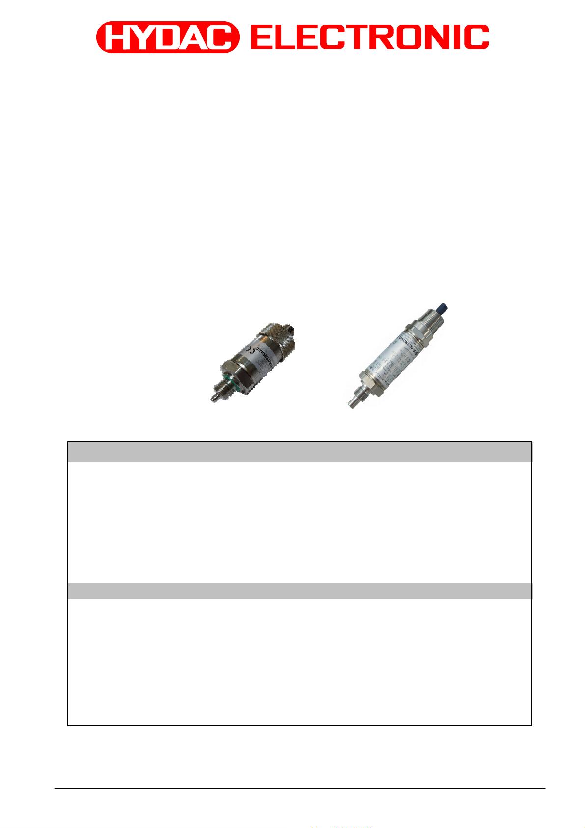
Temperaturmessumformer Serie ETS 4000
mit HART Schnittstelle für eigensichere Stromkreise und
Schutz durch Gehäuse mit ATEX und IECEx-Zulassung
( Original- Bedienungsanleitung )
Operating Instructions
Temperature Transmitter Series ETS 4000
with HART interface for intrinsically safe circuits and
protection by enclosure with ATEX and IECEx approval
(Translation of the original operating instructions )
Schutzklassen und Einsatzbereiche /Protection Types and Zones:
ATEX
I M1 Ex ia I Ma
II 1G Ex ia IIC T6,T5 Ga
II 1/2 G Ex ia IIC T6,T5 Ga/Gb
II 2 G EX ia IIC T6,T5 Gb
13ATEX0031X
II 1D Ex ia IIIC T85°C or T95°C Da
II 1D Ex ta IIIC T80/90/100°C T
II 2D Ex tb IIIC T80/90/100°C Db
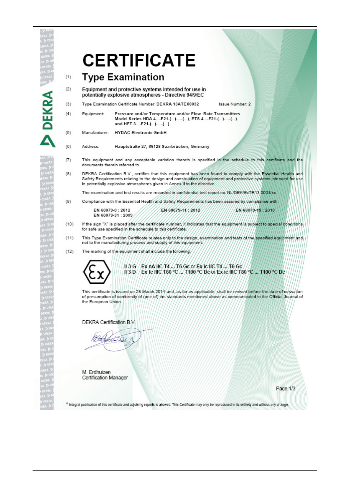
II 3G Ex nA IIC T6, T5, T4 Gc
II 3G Ex ic IIC T6, T5, T4 Gc
13ATEX0032
II 3D Ex tc IIIC T80/T90/T100°C Dc
II 3D Ex ic IIIC T80/T90/T100°C Dc
IECEx
IECEx DEK 14.0011X
ATEX Zertifikat: DEKRA 13ATEX0031 X
DEKRA 13ATEX0032
IECEx Zertifikat: IECEx DEK 14.0011X
Ex ia I Ma
Ex ia IIC T6,T5 Ga
Ex ia IIC T6,T5 Ga/Gb
Ex ia IIC T6,T5 Gb
Ex ia IIIC T85°C or T95°C Da
Ex ta IIIC T80/90/100 °C Da T
Ex tb IIIC T80/90/100 °C Db
Ex nA IIC T6/ T5 T4 Gc
Ex ic IIC T6/ T5/T4 Gc
Ex tc IIIC T80/90/100 °C Dc
Ex ic IIIC T80/90/100 °C Dc
90/100/110 °C Da
500
T90/T100/T110°C Da
500
Stand: 07.06.2016 HYDAC ELECTRONIC GMBH Mat. No.: 669918
Page 2

ETS 4000 Ex ia HART ATEX / IECEx Seite 2 von 30
Inhaltsverzeichnis
1
2
3
4
4.1
4.2
5
6
6.1
6.2
6.3
6.4
Allgemeines ................................................................................................... 3
Funktion ......................................................................................................... 3
Montage und Inbetriebnahme ........................................................................ 3
Wichtige Hinweise für die Conduit-Installation .............................................. 4
Installationshinweise für Geräte mit 1/2 “ NPT Conduit ....................................... 4
Installationshinweise für Geräte mit Schlagschutz .............................................. 5
Allgemeine Sicherheitshinweise .................................................................... 6
Technische Daten .......................................................................................... 7
ETS 4000 Standard ohne Option Druckmessung ............................................... 7
ETS 4000 mit Option Druckmessung .................................................................. 8
Messbereichsgrenzen ......................................................................................... 8
Protokolldaten ..................................................................................................... 8
7
7.1
7.2
8
9
10
11
12
12.1
12.2
13
Typenschlüssel zur Identifikation des gelieferten Gerätes ............................ 9
Typenschlüssel ETS 4000 .................................................................................. 9
Typenschlüssel ETS 4000 mit Option Druckmessung ...................................... 10
Seriennummer ............................................................................................. 10
Abmessungen .............................................................................................. 11
Anschlussbelegung ...................................................................................... 12
Kontrollzeichnung ........................................................................................ 13
Zertifikate ..................................................................................................... 15
ATEX Zertifikat .................................................................................................. 15
IECEx Zertifikat ................................................................................................. 21
Konformitätserklärung .................................................................................. 28
Stand: 07.06.2016 HYDAC ELECTRONIC GMBH Mat. No.:669918
Page 3

ETS 4000 Ex ia HART ATEX / IECEx Seite 3 von 30
1 Allgemeines
Falls Sie Fragen bezüglich der technischen Daten oder Eignung für Ihre Anwendungen haben,
wenden Sie sich bitte an unseren technischen Vertrieb. Die Temperaturmessumformer ETS 4000
werden einzeln auf einem rechnergesteuerten Prüfplatz abgeglichen und einem Endtest unterzogen.
Sie sind wartungsfrei und sollten beim Einsatz innerhalb der Spezifikationen (siehe Technische
Daten) einwandfrei arbeiten. Falls trotzdem Fehler auftreten, wenden Sie sich bitte an den HYDAC-
Service. Nicht vorschriftgemäße Montage oder Fremdeingriffe in das Gerät führen zum Erlöschen
jeglicher Gewährleistungsansprüche sowie der ATEX und IECEx Zulassung.
2 Funktion
Das vom Sensor gemessene Temperatursignal wird in ein analoges 4..20 mA Signal umgewandelt.
Neben der analogen Ausgabe des Messwertes ist eine digitale Kommunikation mit Hilfe des HART
Protokolls möglich. Der elektrische Anschluss erfolgt über einen Steckverbinder oder eine fest
angeschlossene Leitung.
3 Montage und Inbetriebnahme
Die Temperaturmessumformer können auf Prozess-Seite direkt über den Gewindeanschluss montiert
werden. Der Temperatursensor ist in dem vor dem Gewinde befindlichen Zapfen integriert. Um eine
korrekte Temperaturmessung durchzuführen, muss sichergestellt werden, dass sich dieser Zapfen im
Volumenstrom des Fluides befindet.
Anzugsdrehmoment siehe Abmessungen.
Die Installation muss von einem Fachmann nach den jeweiligen Landesvorschriften zu potentiell
explosionsgefährdeten Umgebungen durchgeführt werden (z.B. IEC / EN 60079-14).
Die Temperaturmessumformer der Serie ETS 4000 tragen das - Zeichen. Die Konformitätserklärung
befindet sich im Anhang.
Die Forderungen der Normen (siehe techn. Daten) werden nur bei ordnungsgemäßer und
fachmännischer Erdung des Temperaturmessumformergehäuses mittels des Prozessanschlusses oder
dem ½ NPT Conduit erreicht. Sofern eine grün/gelbe Ader vorhanden ist, darf diese zusätzlich, aber
nicht zur alleinigen Erdung verwendet werden.
Die zugehörigen eigensicheren Geräte (z.B. Zenerbarrieren) sind ebenfalls zu erden.
Ein Potentialausgleich entlang des eigensicheren Stromkreises ist in der Ausführungsvariante N
(Isolationsspannung <= 50 VAC) erforderlich.
Bei der Serie ETS 4000 in der Ausführungsform H (Isolationsspannung ≤ 500 VAC) darf die Kabellänge
zum Temperaturmessumformer maximal 30m betragen (Überspannungsschutz nach DIN EN 61000-6-2).
Wenn die Kabellänge 30m überschreitet, muss der Überspannungsschutz kundenseitig sichergestellt
werden.
Temperaturmessumformer mit Option Druckmessung
Geräte mit einem Nenndruck ≤ 100 bar (≤ 1500 psi) besitzen einen Druckausgleich zum
Umgebungsdruck. Hierzu befindet sich unter der Steckerbefestigung eine kleine Bohrung. Diese ist von
innen mit einer speziellen Membrane abgedeckt, die verhindert, dass Feuchtigkeit von außen in das
Gerät eindringen kann. Um eine Verstopfung der Bohrung zu verhindern, sollte bei feuchter und
staubhaltiger Umgebung die Montage daher waagerecht oder senkrecht mit dem Prozessanschluss nach
unten erfolgen.
Bei Geräten mit einem Nenndruck von ≤ 100 bar (≤ 1500 psi) und einem
½ NPT Conduit befindet sich diese Bohrung am ½ NPT Conduit.
Allgemeine Sicherheitshinweise (vgl. Kapitel 5) sind in jedem Fall zu beachten.
Einbau gemäß Kontrollzeichnungen Nr. 663653 (siehe Kapitel 12).
Stand: 07.06.2016 HYDAC ELECTRONIC GMBH Mat. No.:669918
Page 4
ETS 4000 Ex ia HART ATEX / IECEx Seite 4 von 30
4 Wichtige Hinweise für die Conduit-Installation
4.1 Installationshinweise für Geräte mit 1/2 “ NPT Conduit
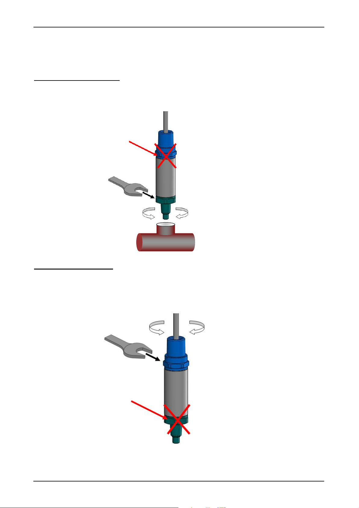
Mechanische Installation
Für die Montage des Prozessanschlusses darf nur die Schlüsselfläche 27mm an der
Prozessanschlussseite des Temperaturmessumformers verwendet werden.
Nicht zum Einschrauben in
die Hydraulikleitung
verwenden!
Elektrische Installation
Die Schlüsselfläche an der Seite des elektrischen Anschlusses am ½ NPT Conduit dient nur zum
Fixieren des Temperaturmessumformers bei der Conduit-Installation.
Nicht zum Fixieren des
Sensors während der Conduit-
Installation verwenden!
Stand: 07.06.2016 HYDAC ELECTRONIC GMBH Mat. No.:669918
Page 5
ETS 4000 Ex ia HART ATEX / IECEx Seite 5 von 30
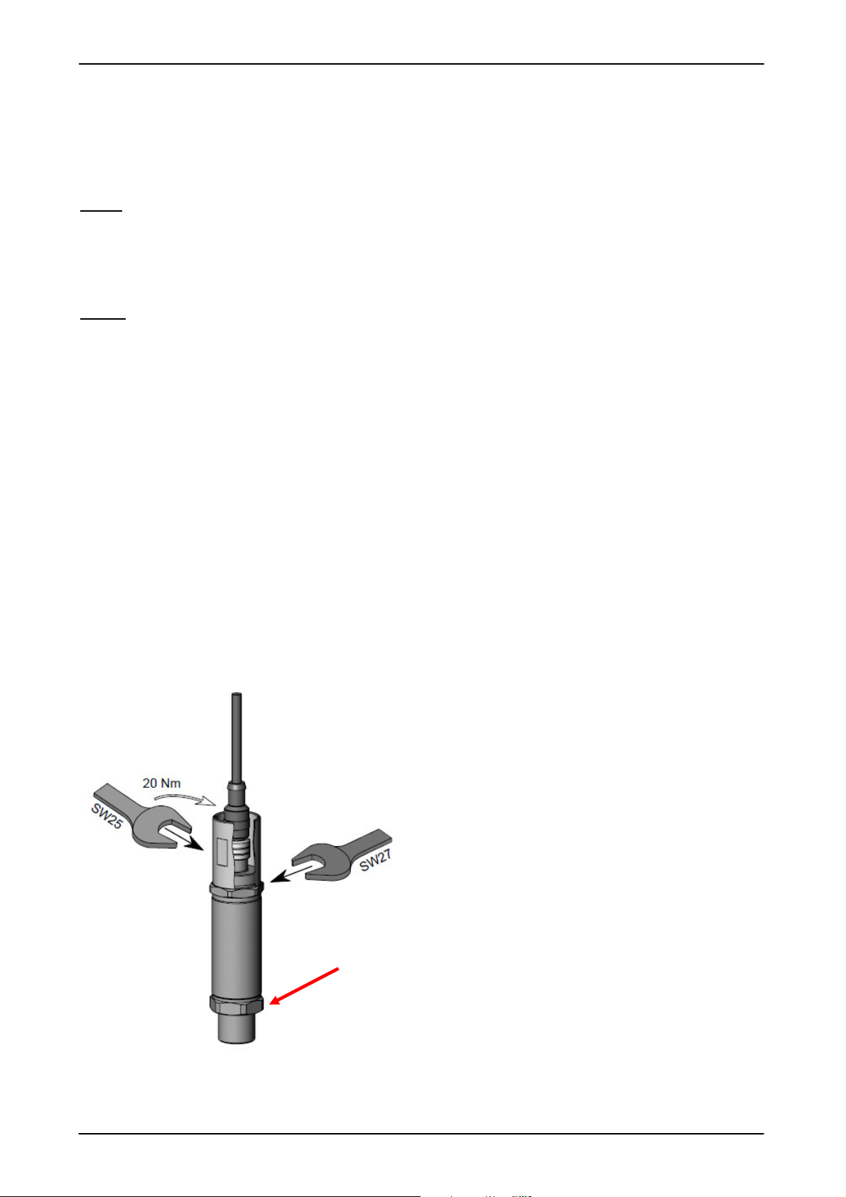
4.2 Installationshinweise für Geräte mit Schlagschutz
Installationshinweise für Geräte mit M12×1 Stecker mit Schlagschutz-/Sicherungs- Metallhülse für
den Einsatz in:
ATEX
II 3G Ex nA IIC T6,T5 Gc
II 1D Ex ta IIIC T80/T90°C T
T90/ T
500
T100 Da
500
II 2D Ex tb III C T80/T90°C Db
IECEx
Ex nA IIC T6,T5 Gc
Ex ta IIIC T80/T90°C T
500
T90/ T
T100 Da
500
Ex tb III C T80/T90°C Db
Zur Einhaltung der Sicherheitsrichtlinien ist, für diese Schutzklassen und Einsatzbereiche, die
Verwendung der Schlagschutz-/ Sicherungs- Metallhülse zwingend erforderlich.
Die Schlüsselfläche 27mm an der Seite des elektrischen Anschlusses dient nur zum Fixieren des
Temperaturmessumformers bei Installation der Schlagschutz-/Sicherungs-Metallhülse.
Die Schlagschutz-/Sicherungs- Metallhülse ist mit einem Anzugsdrehmoment von 20 Nm anzuziehen.
Das Anschlusskabel mit M12x1 Stecker muss im spannungslosen Zustand ordnungsgemäß
angeschlossen und die mitgelieferte Schlagschutz-/Sicherungs-Metallhülse montiert werden. Auch die
Trennung des M12x1 Steckers darf nur im Spannungslosen Zustand erfolgen.
Nicht zum Fixieren des Sensors
während der Installation der
Metallhülse verwenden!
Stand: 07.06.2016 HYDAC ELECTRONIC GMBH Mat. No.:669918
Page 6

ETS 4000 Ex ia HART ATEX / IECEx Seite 6 von 30
5 Allgemeine Sicherheitshinweise
Wenn das Etikett nicht mehr lesbar ist, muss der Temperaturmessumformer außer Betrieb gesetzt
werden.
Sicherheitsbarrieren zum Anschluss der Temperaturmessumformer sind generell in Zündschutzart
"ia" auszuführen.
Die Dichtungen sind in regelmäßigen Abständen, in Abhängigkeit der klimatischen Bedingungen
und dem Medieneinfluss, auf ihre Funktionstüchtigkeit zu kontrollieren, und wenn erforderlich
auszutauschen. Ersatzdichtungen und –flachdichtungen können von der HYDAC ELECTRONIC
GMBH bezogen werden. (Standarddichtungen siehe Technische Daten) Diese Überprüfung muss
mindestens alle drei Jahre durchgeführt werden.
Es ist unbedingt auf die Verträglichkeit der Messmedien zu den Dichtungen und den verwendeten
Werkstoffen des Temperaturmessumformers zu achten. Ebenso sind die im Zertifikat angegebenen
"Sicherheitstechnische Daten" einzuhalten.
Temperaturmessumformer mit Option Druck
Bei gleichzeitigem Einsatz in Zone 0 und 1 wirkt die Druck-Messmembrane des Gerätes als
"Trennwand" zwischen Zone 0 und Zone 1. Die Dicke dieser "Trennwand" ist generell ≤ 1mm und
bei Nenndruck unter 100 bar ≤ 0,2 mm. Zur Sicherstellung dieser Trennfunktion ist unbedingt auf die
Verträglichkeit der Messmedien mit den verwendeten Werkstoffen des Gerätes zu achten, ebenso
sind die Überlast- und Berstdrücke unbedingt einzuhalten (Angaben hierzu siehe "Technische
Daten").
Die interne Messmembrane des Druckmessumformers ist unbedingt vor mechanischer
Beschädigung zu schützen. Dieses gilt insbesondere bei gleichzeitigem Einsatz in Zone 0 und 1
sowie Zone 1 und 2.
Ebenso ist auf eine ausreichende Dichtung zwischen den Zonen zu achten.
Die Daten hinsichtlich der Nutzung in explosionsgefährdeten Umgebungen sind in jedem Fall zu
berücksichtigen.
Der Betrieb ist nur zulässig, wenn anwendungs- und prozessbedingte intensive elektrostatische
Aufladungsprozesse ausgeschlossen sind.
Bei Einsatz in Atmosphären von brennbaren Stäuben ist der Temperaturmessumformer
geschützt vor Beschädigungen und Schlag anzubringen.
Zur Einhaltung der Sicherheitsrichtlinien ist für die Schutzklassen und Einsatzbereiche:
ATEX: II 3G Ex nA IIC T6,T5 Gc / II 1D Ex ta IIIC T80/T90°C T
T90/ T
500
T100 Da /
500
II 2D Ex tb III C T80/T90°C Db
IECEx: Ex nA IIC T6,T5 Gc / Ex ta IIIC T80/T90°C T
T90/ T
500
T100 Da /
500
Ex tb III C T80/T90°C Db
die Verwendung der Schlagschutz-/ Sicherungs- Metallhülse zwingend erforderlich.
Die Schlagschutz-/Sicherungs- Metallhülse ist mit einem Anzugsdrehmoment von 20 Nm anzuziehen.
Stand: 07.06.2016 HYDAC ELECTRONIC GMBH Mat. No.:669918
Page 7
ETS 4000 Ex ia HART ATEX / IECEx Seite 7 von 30
Eingangskenngrößen
Ausgangsgrößen
Lmax
≤
≤
≤
≤
Umgebungsbedingungen
1)2)
1)2)
≤
Relevante Daten für
Ex-
Anwend
ungen
Ex ia, ic
Ex nA, ta, tb, tc
Sonstige Größen
6 Technische Daten
6.1
ETS 4000 Standard ohne Option Druckmessung
ETS 4100 ETS 4500
Messelement Silizium-Halbleiter
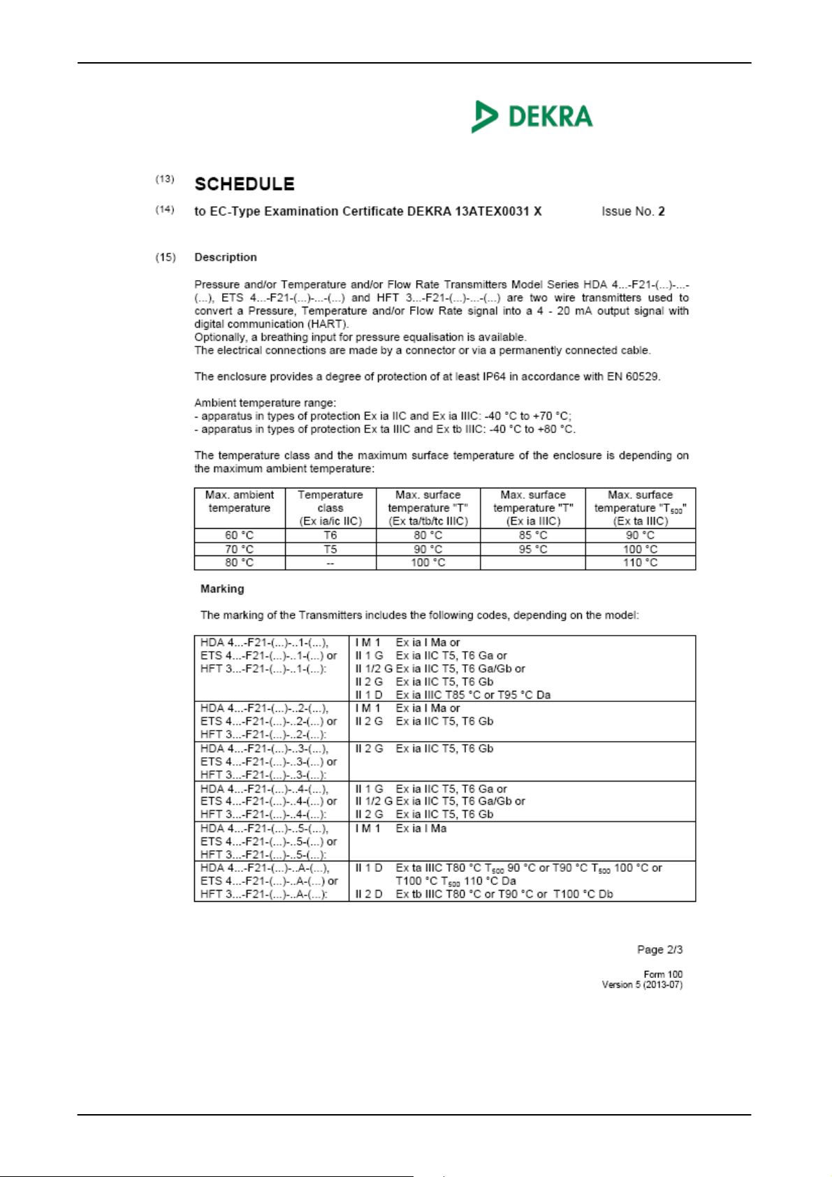
Messbereich -25 .. +100 °C [-13 .. +212 °F]
Fühlerlänge 10,4 (SAE6); 10,7 (G1/4); 50; 100; 250; 350 mm
Druckfestigkeit 600 bar [8700 psi] Fühlerlänge 10,4/ 10,7 mm [0,409/ 0,421 Inch]
125 bar [1800 psi] Fühlerlänge 50 mm [1,97 Inch]
125 bar [1800 psi] Fühlerlänge 100 mm [3,937 Inch]
125 bar [1800 psi] Fühlerlänge 250 mm [9,843 Inch]
125 bar [1800 psi] Fühlerlänge 350 mm [13,779 Inch]
Mechanischer Anschluss
Anzugsdrehmoment siehe Abmessungen
Medien berührende Teile 1.4571(316Ti); 1.4301 (304)
Conduit / Gehäusewerkstoff 1.4404 (316L)
Ausgangssignal
HART Kommunikation gemäß HART 7 Spezifikation
HART Common Practice Commands z.B. Änderung der Messbereichsgrenzen (siehe Tabelle)
Zulässige Bürde R
Genauigkeit (bei Raumtemperatur)
Temperaturdrift
Anstiegszeit nach DIN EN 60751 t50: ~ 10 s
Betriebs- /Umgebungstemperaturbereich
Mediumstemperaturbereich
Lagertemperaturbereich -40 .. +100 °C [-40 .. +212 °F]
- Zeichen
Vibrationsbeständigkeit nach
IEC 60068-2-6 bei 10 ..500 Hz
Schutzart nach IEC 60529 3)
ISO 20653
Versorgungsspannung 12...28 VDC 12...28 VDC
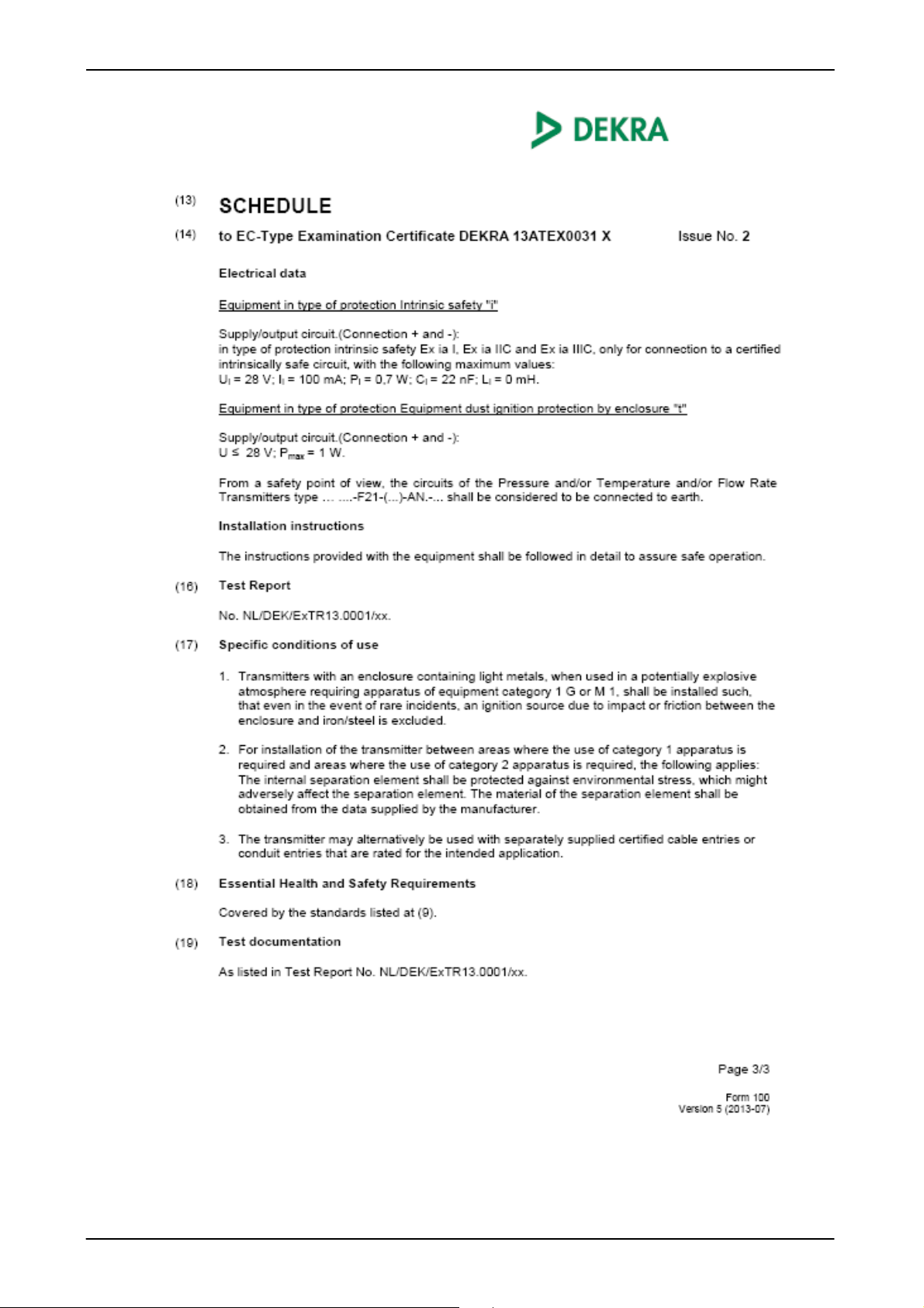
Maximaler Speisestrom Ii = 100 mA
Maximale Speiseleistung Pi = 0,7 W Max. Leistungsaufnahme ≤ 1W
Anschlusskapazität des Sensors
Induktivität des Sensors Li = 0 mH
Isolationsspannung 50 VAC, mit integriertem Überspannungsschutz nach
Restwelligkeit Versorgungsspannung 46 bis 125 Hz: < 0,2 Vpp
Gewicht ca. 280 g Fühlerlänge 10,4/10,7 mm [0,409/ 0,421 Inch]
Hinweise:
FS (Full Scale) = bezogen auf den vollen Messbereich
1)
-20 °C [-4 °F] mit FPM Dichtung, Dichtungsmaterial bis -40°C [-40 °F] auf Anfrage
2)
mit M12x1 Stecker nur bis -25°C [-13°F]möglich
3)
bei montierter Kupplungsdose entsprechender Schutzart
G1/4 A ISO 1179-2 (DIN 3852)
9/16-18 UNF 2A (SAE6)
1/4-18 NPT
Dichtung: FPM (SAE6 und G1/4)
4 .. 20 mA über HART Protokoll
.= (UB – 12 V) / 20 mA [kΩ], für HART Kommunikation min. 250Ω
± 0,4 % FS typ.
≤ ± 0,8 % FS max.
± 0,01 % FS/°C [0,006 % FS/°F]
± 1,0 % FS typ.
≤ ± 2,0 % FS max.
± 0,02% FS /°C [0,01 % FS /°F]
t90: ~ 15 s
T6,T80,T85°C,T
T5,T90,T95°C,T
T100,T
T4 Ta=-40..+85°C/-20 .. +85 °C[-40 .. +185°F/-4 .. +185 °F]
T6,T80,T85°C,T
T5,T90,T95°C,T
T100,T
T4 Ta=-40..+85°C/-20 .. +85 °C[-40 .. +185°F/-4 .. +185 °F]
110 Ta=-40..+80°C/-20 .. +80 °C[-40 .. +176°F/-4 .. +176 °F]
500
110 Ta=-40..+80°C/-20 .. +80 °C[-40 .. +176°F/-4 .. +176 °F]
500
90 Ta=-40..+60°C/ -20 .. +60°C[-40 .. +140°F/ -4 .. +140 °F]
500
100 Ta=-40..+70°C/-20 .. +70 °C[-40 .. +158°F/-4 .. +158 °F]
500
90 Ta=-40..+60°C/ -20 .. +60°C[-40 .. +140°F/ -4 .. +140 °F]
500
100 Ta=-40..+70°C/-20 .. +70 °C[-40 .. +158°F/-4 .. +158 °F]
500
EN 61000-6-1 / 2 / 3 / 4
EN 60079-0/ 11/ 15/ 26/ 31
20 g
≤ 10 g (mit 1/2 NPT Conduit)
IP 67 (Gerätestecker M12x1, EN175301-803)
IP 6K9K (mit 1/2 NPT Conduit)
Ci = ≤ 22 nF
EN 61000-6-2
>125 Hz: <1,2 mV RMS
ca. 300 g Fühlerlänge 50 mm [ 1,97 Inch]
ca. 315 g Fühlerlänge 100 mm [ 3,937 Inch]
ca. 350 g Fühlerlänge 250 mm [ 9,843 Inch]
ca. 385 g Fühlerlänge 350 mm [13,779 Inch]
Stand: 07.06.2016 HYDAC ELECTRONIC GMBH Mat. No.:669918
Page 8
ETS 4000 Ex ia HART ATEX / IECEx Seite 8 von 30
Eingansgrößen
ETS 4100
ETS 4500
Ausgangsgrößen
Typ.
Umgebungsbedingungen
6.2
ETS 4000 mit Option Druckmessung
Allgemeingültige techn. Daten: Siehe 6.1 ETS 4100 / ETS 4500 Standard
Zusätzliche technische Daten mit Option Druckmessung:
Messbereich bar
Überlastbereich bar
Berstdruck bar
Messbereich psi
Überlastbereich psi
Berstdruck psi
Mechanischer Anschluss G 1/2 A DIN 3852 mit Fühler
Anzugsdrehmoment Siehe Abmessungen
Medienberührende Teile Edelstahl: 1.4542(630); 1.4548(630)
Fühlerlänge 7 mm
Ausgangssignal Druck Das Drucksignal ist als Sekundärvariable über HART Protokoll als digitales
Genauigkeit nach DIN16086
Grenzpunkteinstellung
Genauigkeit bei Kleinstwerteinstellung
(B.F.S.L)
Temperaturkompensation Typ.
Nullpunkt max
Temperaturkompensation Typ.
Spanne max
Nicht-Linearität bei Grenzpunkteinstellung nach DIN 16086
Hysterese max
Wiederholbarkeit
Langzeitdrift Typ.
16 40 60 100 250 400 600
32 80 120 200 500 800 1000
100 200 300 500 1000 2000 2000
300 500 1000 3000 5000 6000 9000
725 1160 2900 7250 11600 11600 14500
1800 2900 7250 14500 29000 29000 29000
Dichtung: FPM
Signal verfügbar.
Typ.
≤ ± 0,25 % FS
Max
≤ ± 0,5 % FS
≤ ± 0,15 % FS
Max
≤ ± 0,25 % FS
≤ ± 0,008 % /°C [0,004% FS /°F] ≤ ± 0,015 % /°C [0,008% FS /°F]
≤ ± 0,015 % /°C [0,008% FS /°F] ≤ ± 0,025 % /°C [0,014% FS /°F]
≤ ± 0,008 % /°C [0,004% FS /°F] ≤ ± 0,015 % /°C [0,008% FS /°F]
≤ ± 0,015 % /°C [0,008% FS /°F] ≤ ± 0,025 % /°C [0,014% FS /°F]
max
≤ ± 0,3% FS ≤ ± 0,3% FS
≤ ± 0,1 % FS ≤ ± 0,4 % FS
≤ ± 0,05 % FS ≤ ± 0,1 % FS
≤ ± 0,1 % FS / Jahr ≤ ± 0,3 % FS / Jahr
≤ ± 0,5 % FS
≤ ± 1,0 % FS
≤ ± 0,25 % FS
≤ ± 0,5 % FS
Kompensierter Temperaturbereich -25 .. +85 °C
Schutzart nach IEC 60529 1)
ISO 20653
Lebensdauer >10 Mio. Lastwechsel 0 .. 100 % FS
1)
bei montierter Kupplungsdose entsprechender Schutzart
IP 65 (bei ½ NPT Conduit ≤ 100 bar)
IP 67 (Gerätestecker M12x1, EN175301-803)
IP 6K9K (bei ½ NPT Conduit > 100 bar)
6.3
Messbereichsgrenzen
Mittels HART Common Practice Commands haben Sie die Möglichkeit folgende Messbereichsgrenzen
einzustellen:
Messbereichsgrenzen der Primärvariablen Temperatur:
Untere Messbereichsgrenze Obere Messbereichsgrenze Messspanne
min max min max min max
-25°C 75°C 0°C 100°C 25°C 125°C
-13°F 167°F 32°F 212°F -13°F 257°F
Für Geräte mit Option Druckmessung ETS 4000-P:Messbereichsgrenzen der Sekundärvariablen, Druck:
Untere Messbereichsgrenze Obere Messbereichsgrenze Messspanne
min max min max min max
0 % FS 112,5 % FS 37,5 % FS 150 % FS 37,5 % FS 150 % FS
6.4
HART Version: 7
Manufacturer Code: 0x605E
Manufacturer String: HYDAC ELECTRONIC
Device Type Code: 0xE2A8 Variante mit Temperatur als PV und einziger Messgröße.
Stand: 07.06.2016 HYDAC ELECTRONIC GMBH Mat. No.:669918
Protokolldaten
0xE2A9 Variante mit Temperatur als PV und Druck als SV.
Page 9
ETS 4000 Ex ia HART ATEX / IECEx Seite 9 von 30
Ex ta IIIC T80/T90°C Da
Anschlussart mechanisch
Elektrischer Anschluss
Zulassung
Modifikationsnummer
nung
Schutzklassen und Einsatzgebiete
Genauigkeit
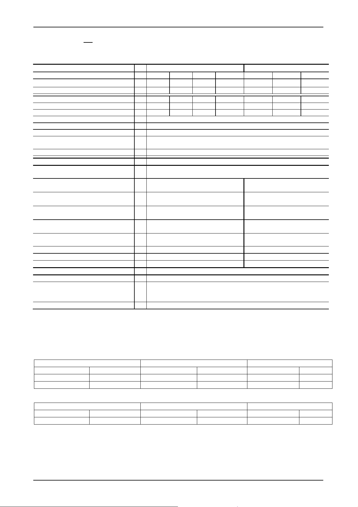
7 Typenschlüssel zur Identifikation des gelieferten Gerätes
7.1
1 = 0,4% typ
5 = 1% typ
4 = G 1/4 A ISO 1179-2 (DIN 3852), außen
7 = 9/16-18 UNF 2A (SAE6), außen (nur für Fühlerlänge „010“)
8 = 1/4-18 NPT, außen
(nur für Fühlerlänge „50“, „100“, „250“, „500“)
5 = Gerätestecker, EN 175301-803, 3 pol. + PE
6 = Gerätestecker, M 12 x 1, 4 pol.
9 = 1/2-14 NPT Conduit (Außengewinde), Einzelader
G = 1/2-14 NPT Conduit (Außengewinde), freies Kabelende
Signal
F21 = 4 .. 20 mA ( mit HART Interface)
Fühlerlänge
010 = 10,4 /10,7 mm [0,409/ 0,421 Inch] (nur mit SAE6 oder G1/4)
050= 50 mm [1,97 Inch]
100 = 100 mm [3,937 Inch] (nur mit G1/4 oder 1/4-18 NPT)
250 = 250 mm [9,843 Inch] (nur mit G1/4 oder 1/4-18 NPT)
350 = 350 mm [13,779 Inch] (nur mit G1/4 oder 1/4-18 NPT)
Typenschlüssel ETS 4000
ETS 4 X X X - F21 - XXX – E X X - XXX (XXX”)
E = ATEX + IECEx
Isolationsspan
H = 500 V AC gegen Gehäuse
N = 50 V AC gegen Gehäuse
ATEX IECEx
1 = I M1 Ex ia I Ma
II 1G Ex ia IIC T6,T5 Ga
II 1/2 G Ex ia IIC T6,T5 Ga/Gb
II 2 G Ex ia IIC T6,T5 Gb
II 1D Ex ia IIIC T85°C/T95°C Da
9 = II 3G Ex nA IIC T6, T5 Gc Ex nA IIC T6, T5 Gc
nur mit elektrischem Anschluss „6“
A = II 1D Ex ta IIIC T80/T90°C
T
II 2D Ex tb IIIC T80/T90°C Db
nur mit elektrischem Anschluss „6“
C = II 3G Ex ic IIC T6, T5 Gc
II 3D Ex ic IIIC T80/T90°C Dc
500
T90/ T
T100 Da
500
000 = Standard
Ex ia I Ma
Ex ia IIC T6,T5 Ga
Ex ia IIC T6,T5 Ga/Gb
Ex ia IIC T6,T5 Gb
Ex ia IIIC T85°C/T95°C Da
T
Ex tb IIIC T80/T90°C Db
Ex ic IIC T6, T5 Gc
Ex ic IIIC T80/T90°C Dc
500
T90/ T
100°C Da
500
Kabellänge (z.B. für Conduit-Rohranschluss oder freies Kabelende)
Angaben in m oder “ (inch)
Stand: 07.06.2016 HYDAC ELECTRONIC GMBH Mat. No.:669918
Page 10
ETS 4000 Ex ia HART ATEX / IECEx Seite 10 von 30
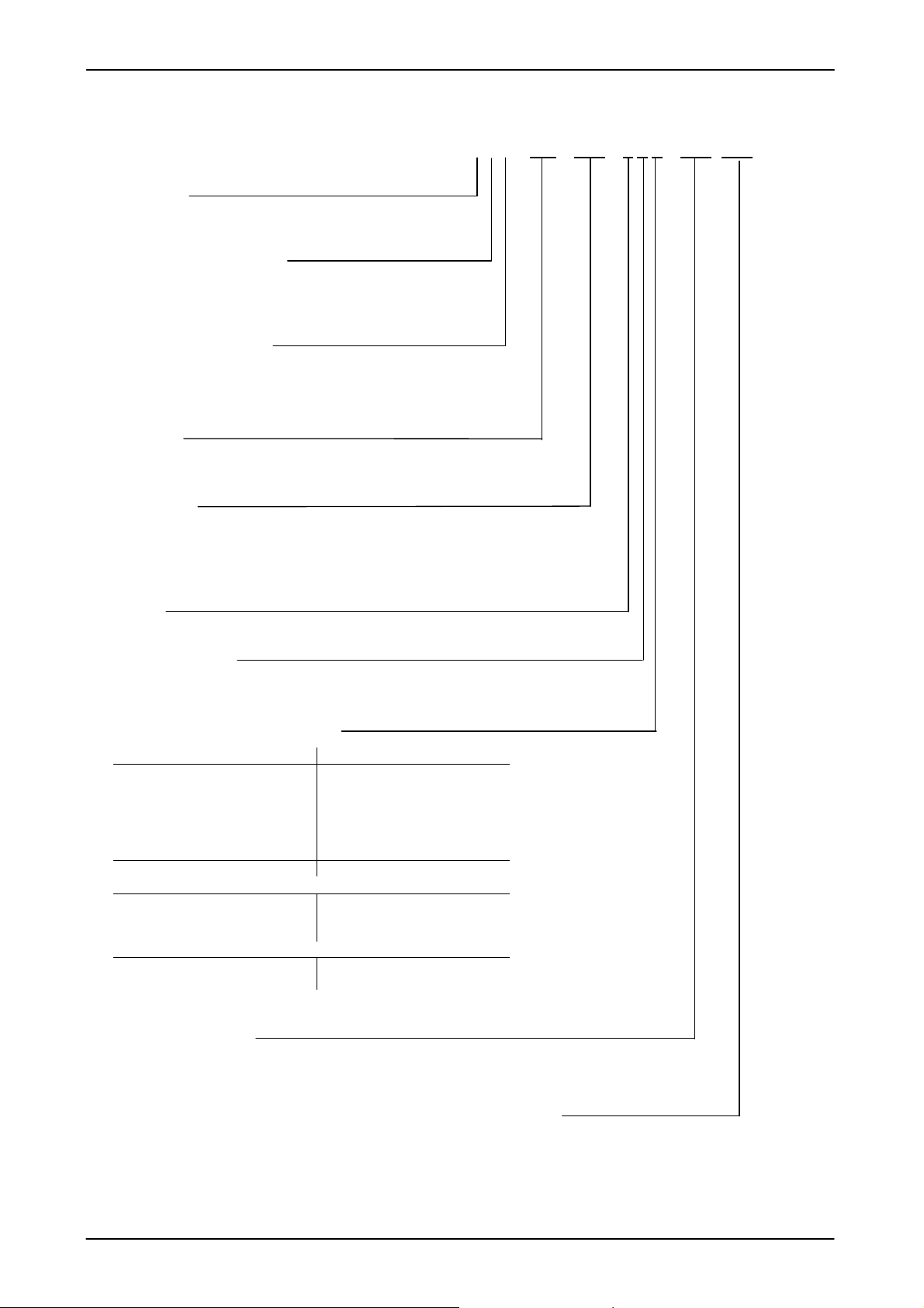
Anschlussart mechanisch
7.2
2 = G 1/2 A ISO 1179-2 (DIN 3852), Außengewinde
Fühlerlänge
007 = 7 mm [0,276 inch]
Typenschlüssel ETS 4000 mit Option Druckmessung
ETS 4 X 2 X - F21 - 007 - P - XXXXX - E X X - XXX (XXX”)
Optional mit Druckmessung
Digital mit HART Schnittstelle
Messbereiche
4 stellig für bar-Version
0016; 0040; 0060; 0100; 0250; 0400; 0600
5 stellig für psi-version
00300;00500; 01000; 03000; 05000; 06000; 09000
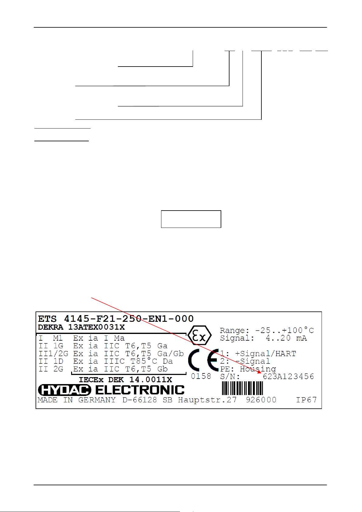
8 Seriennummer
Die Seriennummer enthält die Kalenderwoche und das Jahr, in dem das Gerät hergestellt
wurde, neben der sequentiellen Seriennummer.
xxyykzzzzzz
Aufbau Seriennummer:
X Fertigungsjahr z. B. : 6 2016
yy Kalenderwoche z. B.: 23 KW23
k Seriennummer-Index z. B : -,A,B
zzzzzz fortlaufende Seriennummer z. B.: 123456
Stand: 07.06.2016 HYDAC ELECTRONIC GMBH Mat. No.:669918
Page 11
ETS 4000 Ex ia HART ATEX / IECEx Seite 11 von 30
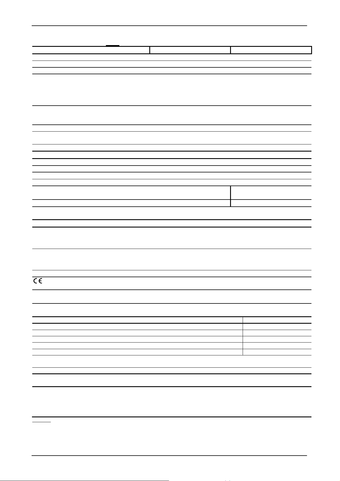
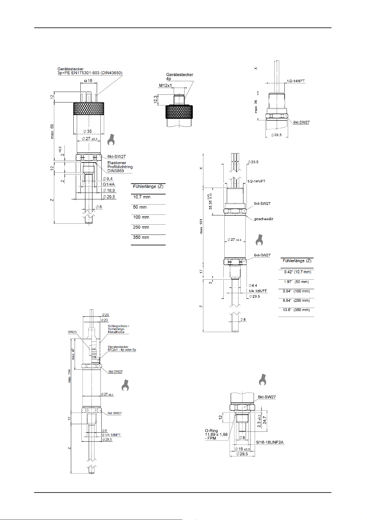
20 Nm
4
0 Nm
20 Nm
20 Nm
40 Nm
20 Nm
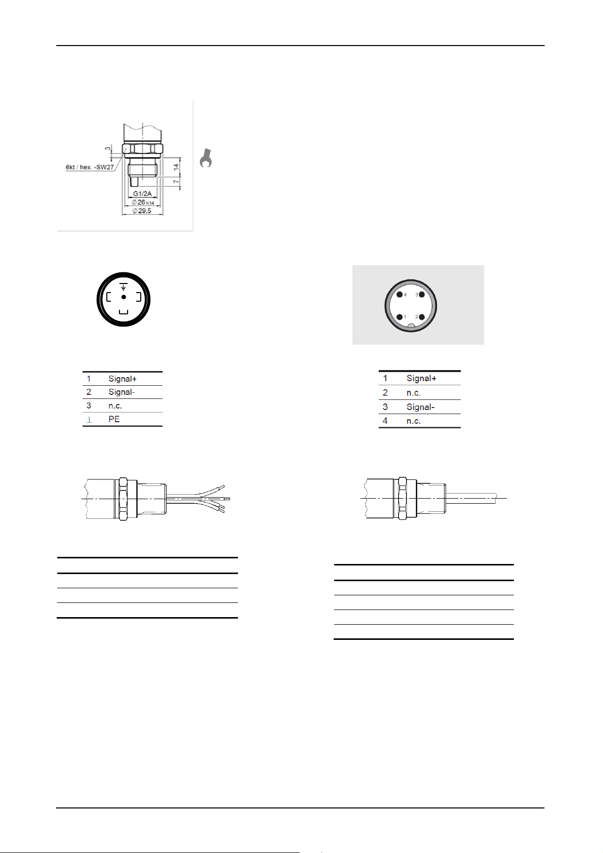
9 Abmessungen
Stand: 07.06.2016 HYDAC ELECTRONIC GMBH Mat. No.:669918
Page 12
ETS 4000 Ex ia HART ATEX / IECEx Seite 12 von 30
Ader
ETS 45x9
-
F21
Ader
ETS 45xG
-
F21
45 Nm
Mechanischer Anschluss mit Option Druckmessung
10 Anschlussbelegung
Stecker EN 175301-803 Stecker M12x1
ETS 4xx5-F21: ETS 4xx6-F21
Conduit (Einzelader) Conduit (Freies Kabelende)
rot Signal +
schwarz Signal grün-gelb Gehäuse
weiß Signal braun Signal +
grün n.c.
gelb n.c.
Stand: 07.06.2016 HYDAC ELECTRONIC GMBH Mat. No.:669918
Page 13
ETS 4000 Ex ia HART ATEX / IECEx Seite 13 von 30
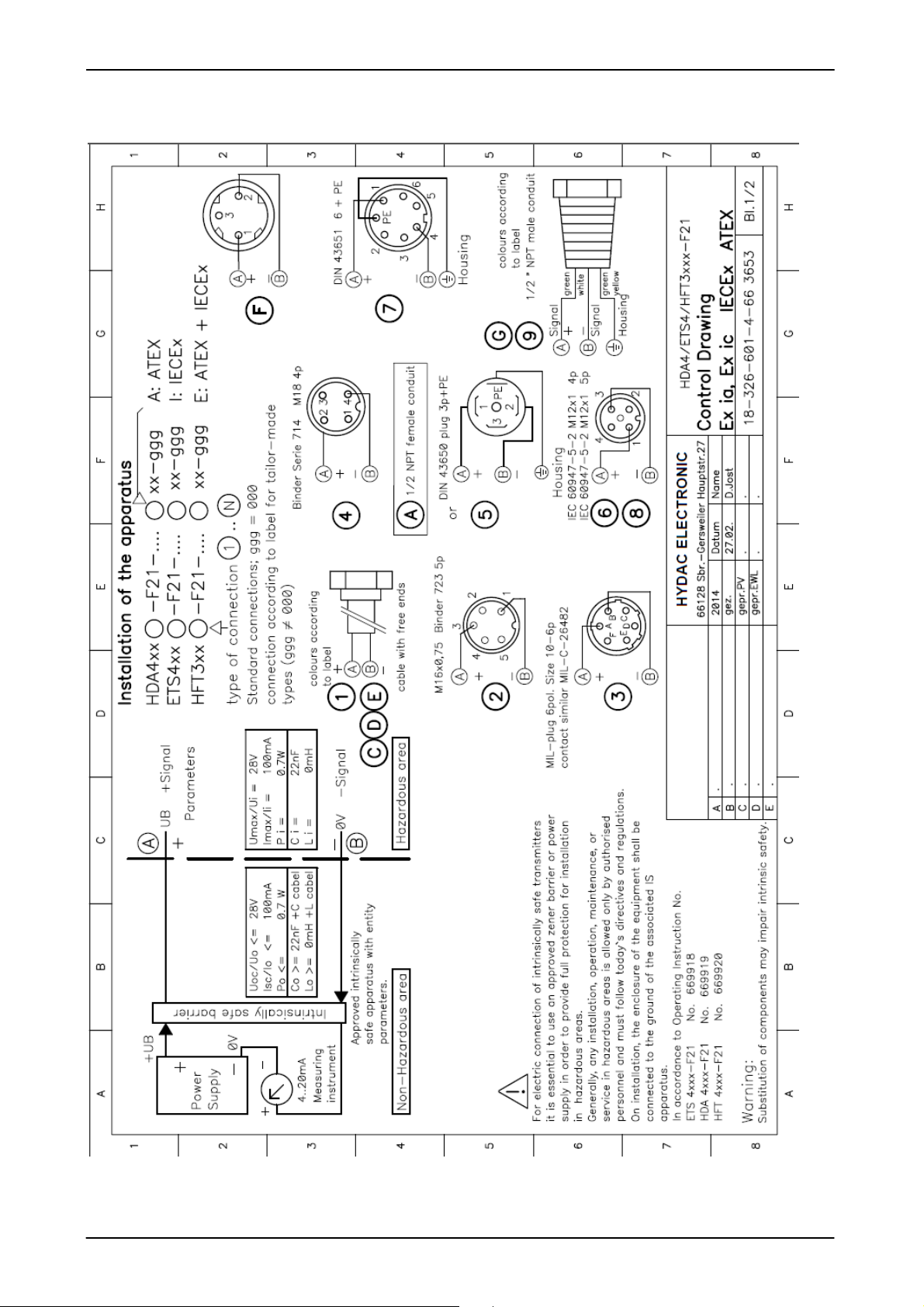
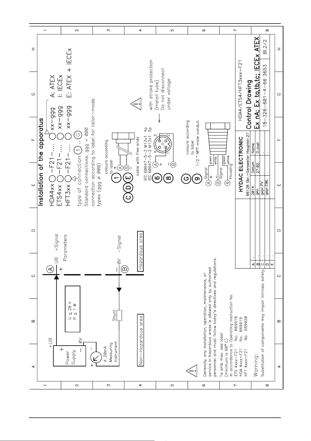
11 Kontrollzeichnung
Stand: 07.06.2016 HYDAC ELECTRONIC GMBH Mat. No.:669918
Page 14
ETS 4000 Ex ia HART ATEX / IECEx Seite 14 von 30
Stand: 07.06.2016 HYDAC ELECTRONIC GMBH Mat. No.:669918
Page 15
ETS 4000 Ex ia HART ATEX / IECEx Seite 15 von 30
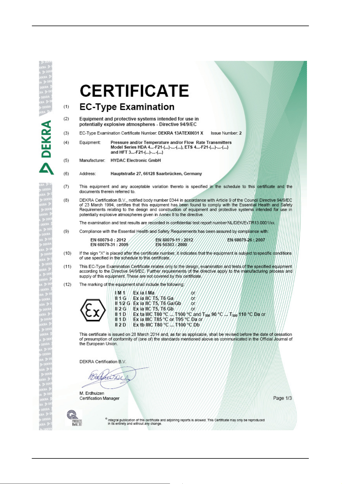
12 Zertifikate
12.1
ATEX Zertifikat
Stand: 07.06.2016 HYDAC ELECTRONIC GMBH Mat. No.:669918
Page 16
ETS 4000 Ex ia HART ATEX / IECEx Seite 16 von 30
Stand: 07.06.2016 HYDAC ELECTRONIC GMBH Mat. No.:669918
Page 17
ETS 4000 Ex ia HART ATEX / IECEx Seite 17 von 30
Stand: 07.06.2016 HYDAC ELECTRONIC GMBH Mat. No.:669918
Page 18
ETS 4000 Ex ia HART ATEX / IECEx Seite 18 von 30
Stand: 07.06.2016 HYDAC ELECTRONIC GMBH Mat. No.:669918
Page 19

ETS 4000 Ex ia HART ATEX / IECEx Seite 19 von 30
Stand: 07.06.2016 HYDAC ELECTRONIC GMBH Mat. No.:669918
Page 20

ETS 4000 Ex ia HART ATEX / IECEx Seite 20 von 30
Stand: 07.06.2016 HYDAC ELECTRONIC GMBH Mat. No.:669918
Page 21

ETS 4000 Ex ia HART ATEX / IECEx Seite 21 von 30
12.2
IECEx Zertifikat
Stand: 07.06.2016 HYDAC ELECTRONIC GMBH Mat. No.:669918
Page 22

ETS 4000 Ex ia HART ATEX / IECEx Seite 22 von 30
Stand: 07.06.2016 HYDAC ELECTRONIC GMBH Mat. No.:669918
Page 23

ETS 4000 Ex ia HART ATEX / IECEx Seite 23 von 30
Stand: 07.06.2016 HYDAC ELECTRONIC GMBH Mat. No.:669918
Page 24

ETS 4000 Ex ia HART ATEX / IECEx Seite 24 von 30
Stand: 07.06.2016 HYDAC ELECTRONIC GMBH Mat. No.:669918
Page 25

ETS 4000 Ex ia HART ATEX / IECEx Seite 25 von 30
Stand: 07.06.2016 HYDAC ELECTRONIC GMBH Mat. No.:669918
Page 26

ETS 4000 Ex ia HART ATEX / IECEx Seite 26 von 30
Stand: 07.06.2016 HYDAC ELECTRONIC GMBH Mat. No.:669918
Page 27

ETS 4000 Ex ia HART ATEX / IECEx Seite 27 von 30
Stand: 07.06.2016 HYDAC ELECTRONIC GMBH Mat. No.:669918
Page 28

ETS 4000 Ex ia HART ATEX / IECEx Seite 28 von 30
13 Konformitätserklärung
Stand: 07.06.2016 HYDAC ELECTRONIC GMBH Mat. No.:669918
Page 29

ETS 4000 Ex ia HART ATEX / IECEx Seite 29 von 30
Stand: 07.06.2016 HYDAC ELECTRONIC GMBH Mat. No.:669918
Page 30

ETS 4000 Ex ia HART ATEX / IECEx Seite 30 von 30
HYDAC ELECTRONIC GMBH
Hauptstraße 27
D - 66 128 Saarbrücken
Deutschland
Web: www.hydac.com
E-Mail: electronic@hydac.com
T
el.: +49-(0)6897-509-01
Fax.: +49 (0)6897 509-1726
HYDAC Service
Für Fragen zu Reparaturen steht Ihnen der HYDAC Service zur Verfügung:
HYDAC SERVICE GMBH
Hauptstr. 27
D - 66 128 Saarbrücken
Deutschland
T
el.: +49-(0)6897-509-1936
Fax.: +49 (0)6897 509-1933
Anmerkung
Die Angaben in diesem Handbuch beziehen sich auf die beschriebenen
Betriebsbedingungen und Einsatzfälle. For applications or operating conditions not
described, please contact the relevant technicaldepartment.
Bei technischen Fragen, Hinweisen oder Störungen nehmen Sie bitte Kontakt mit Ihrer
HYDAC-Vertretung auf.
Technische Änderungen sind vorbehalten.
Stand: 07.06.2016 HYDAC ELECTRONIC GMBH Mat. No.:669918
Page 31

13ATEX0031X
13ATEX0032
IECEx DEK 14.0011X
Operating Instructions
Temperature Transmitter Series ETS 4000
with HART interface
for intrinsically safe circuits and protection by
enclosure
with ATEX and IECEx approval
(Translation of the original operating instructions )
Protection Types and Zones:
ATEX
I M1 Ex ia I Ma
II 1G Ex ia IIC T6,T5 Ga
II 1/2 G Ex ia IIC T6,T5 Ga/Gb
II 2 G EX ia IIC T6,T5 Gb
II 1D Ex ia IIIC T85°C or T95°C Da
II 1D Ex ta IIIC T80/90/100°C T
II 2D Ex tb IIIC T80/90/100°C Db
II 3G Ex nA IIC T6, T5, T4 Gc
II 3G Ex ic IIC T6, T5, T4 Gc
II 3D Ex tc IIIC T80/T90/T100°C Dc
II 3D Ex ic IIIC T80/T90/T100°C Dc
IECEx
ATEX certificate: DEKRA 13ATEX0031 X
DEKRA 13ATEX0032
IECEx Certificate: IECEx DEK 14.0011X
Ex ia I Ma
Ex ia IIC T6,T5 Ga
Ex ia IIC T6,T5 Ga/Gb
Ex ia IIC T6,T5 Gb
Ex ia IIIC T85°C or T95°C Da
Ex ta IIIC T80/90/100 °C Da T
Ex tb IIIC T80/90/100 °C Db
Ex nA IIC T6/ T5 T4 Gc
Ex ic IIC T6/ T5/T4 Gc
Ex tc IIIC T80/90/100 °C Dc
Ex ic IIIC T80/90/100 °C Dc
T90/T100/T110°C Da
500
90/100/110 °C Da
500
Status: 2016-06-07 HYDAC ELECTRONIC GMBH Part No.: 669918
Page 32

ETS 4000 Ex ia HART ATEX / IECEx Page 2 of 30
Table of Contents
1
2
3
4
4.1
4.2
5
6
6.1
6.2
6.3
General .......................................................................................................... 3
Function ......................................................................................................... 3
Installation and Commissioning Information .................................................. 3
Important Mounting Instructions for Conduit Connection .............................. 4
Installation Instructions for Units with 1/2 “ NPT Conduit .................................... 4
Installation Instructions for units with impact protection ...................................... 5
General safety precautions ............................................................................ 6
Technical Data ............................................................................................... 7
ETS 4000 Standard without pressure measurement ......................................... 7
ETS 4000 with pressure measurement as an option .......................................... 8
Measuring Range Limits ..................................................................................... 8
6.4
7
7.1
7.2
8
9
10
11
12
12.1
12.2
13
Protocol Data ...................................................................................................... 8
Model code to identify the delivered part ....................................................... 9
Model Code ETS 4000 ........................................................................................ 9
Model code ETS 4000 with pressure measurement as an option ..................... 10
Serial Number .............................................................................................. 10
Dimensions .................................................................................................. 11
PIN connection ............................................................................................ 12
Control Drawing ........................................................................................... 13
Certificates ................................................................................................... 15
Certificate ATEX ............................................................................................... 15
Certificate IECEx ............................................................................................... 21
Declaration of conformity ............................................................................. 28
Status: 2016-06-07 HYDAC ELECTRONIC GMBH Part No.: 669918
Page 33

ETS 4000 Ex ia HART ATEX / IECEx Page 3 of 30
1 General
If you have any queries regarding technical details or the suitability of the unit for your application,
please contact our Technical Sales Department. The ETS 4000 temperature transmitters are
individually tested and calibrated at a computer operated test station. They are maintenance-free
and operate perfectly when used according to the data (see Technical Specifications). However, if
there is a cause for complaint, please contact HYDAC Service. Incorrect use or interference by
anyone other than HYDAC personnel will cause all warranty claims and ATEX and IECEx approvals
to become null and void.
2 Function
The temperature signal measured by the sensor is converted into an analog 4 .. 20 mA Signal. In
addition with the analogue output of the measured value, digital communication is possible by
means of the HART protocol. Connection to the power supply is carried out via a plug connector or a
permanently connected line.
3 Installation and Commissioning Information
The temperature transmitters can be installed directly on the process side via the threaded connection.
The temperature sensor is built into the stem before the thread. In order to perform correct
measurements, ensure the stem is immersed in the flow of the fluid.
Tightening torque see dimensions.
Connection is to be carried out by a properly qualified specialist in accordance with the pertinent
regulations pertaining to potentially explosive environments (e.g. EN 60079-14).The temperature
transmitters of the ETS 4000 series are -marked. The certificate of conformity is to be found in the
annex.
The requirements of the standards (see technical data) cannot be satisfied unless the temperature
transmitter housing is properly grounded via the mechanical connection or the ½ NPT Conduit. If a
green-yellow wire is available, it can be used additionally for grounding, but may not be used on its own
as the grounding connection.
The related intrinsically safe devices (e.g. zener barriers) must also be grounded.
A potential equalisation is required along the intrinsically safe electrical circuit in the N type model
(insulation voltage ≤ 50 VAC).
On the ETS 4000 series, type H (isolation voltage ≤ 500 VAC), the cable length to the temperature
transmitter must be max. 30 m (overvoltage protection to DIN EN 61000-6-2). If the cable length
exceeds 30 m, overvoltage protection must be provided by the customer.
For temperature transmitters with optional pressure measurement
Devices with a rated pressure of ≤ 100 bar (≤ 1500 psi) provide for pressure equalisation with the
ambient pressure. This is enabled by a small hole underneath the plug connector. The connector is
covered on the inside by a special membrane which prevents moisture from seeping into the unit from
the outside. In order to prevent the hole from becoming clogged, mounting should be carried out in a
horizontal position in moist or dusty environments, or vertically with the pressure port pointing
downwards.
On devices with a rated pressure of ≤ 100 bar (≤ 1500 psi) and a
1
/2 NPT Conduit, this bore is located at the 1/2 NPT Conduit.
The General Safety Precautions (cf. section 5) must be adhered to in any event.
Installation per Control Drawings No. 663653 (see chapter 12).
Status: 2016-06-07 HYDAC ELECTRONIC GMBH Part No.: 669918
Page 34

ETS 4000 Ex ia HART ATEX / IECEx Page 4 of 30
4 Important Mounting Instructions for Conduit Connection
4.1 Installation Instructions for Units with 1/2 “ NPT Conduit
Mechanical Connection
The process connection of the temperature transmitter may only be carried out utilizing the hex.
27mm flats on the process connection side.
Do not use for screwing
into the mechanical
connection!
Electrical Installation
The flat at the electrical connection side next to the 1/2 NPT Conduit only serves to fix the
temperature transmitter during conduit installation.
Do not use for fixing the sensor
during electrical conduit
installation!
Status: 2016-06-07 HYDAC ELECTRONIC GMBH Part No.: 669918
Page 35

ETS 4000 Ex ia HART ATEX / IECEx Page 5 of 30
4.2 Installation Instructions for units with impact protection
Installation instructions for units with M12x1 connector with an impact protected metal safety sleeve
for the use in zones:
ATEX
II 3G Ex nA IIC T6,T5 Gc
II 1D Ex ta IIIC T80/T90°C T
T90/ T
500
T100 Da
500
II 2D Ex tb III C T80/T90°C Db
IECEx
Ex nA IIC T6,T5 Gc
Ex ta IIIC T80/T90°C T
500
T90/ T
T100 Da
500
Ex tb III C T80/T90°C Db
By adherence to safety guidelines in the protection rating and applications, the usage of the impact
protected metal safety sleeve is stringently required.
The electrical installation of the temperature sensor may only be carried out utilizing the hex. 27 mm
flats on the installation of the impact protected metal safety sleeve.
The impact protected metal safety sleeve must be tightened with a torque of 20 Nm.
The connection of the cable with M12x1 plug may only be carried out in de-energized state and in
combination with the impact protected metal safety sleeve. Also the separation of the M12x1
connector may only be carried out if the system is switched off.
Do not use for fixing the sensor
during metal sleeve installation!
Status: 2016-06-07 HYDAC ELECTRONIC GMBH Part No.: 669918
Page 36

ETS 4000 Ex ia HART ATEX / IECEx Page 6 of 30
5 General safety precautions
The temperature transmitter may no longer be used when the label becomes illegible.
Intrinsic safety barriers with protection type „ia“ are to be used for connecting to the temperature
transmitters.
The seals and gaskets are to be checked to see that they function properly prior to mounting and at
regular intervals in keeping with the climatic conditions and the influence of the media, and to be
changed as needed. Replacement seals and gaskets can be obtained from HYDAC ELECTRONIC
GMBH. (Standard seal see technical data) This check is to be conducted at least every three years.
Ensure that the measured fluids are compatible with materials of the seals and the materials of the
temperature transmitter used. Similarly, the "Safety-relevant Data" specified in the certificate must
be adhered to.
For temperature transmitters with optional pressure measurement function
If used simultaneously in zones 0 and 1, the pressure membrane of the device serves as a partition
wall between zones 0 and 1. The thickness of this partition wall is generally ≤ 1mm, and with a
nominal pressure ranging below 100 bar, ≤ 0.2 mm. In order to ensure this partition function, the
compatibility of the measuring fluids with the used device materials is compulsory, as well as the
overload and bursting pressures must absolutely be complied with (further details, please see
"Technical Data").
The internal measurement membrane of the pressure transmitter is to be protected against
mechanical damage. This applies especially if the unit is used simultaneously in zones 0 and 1
equally zones 1 and 2
Please ensure sufficient sealing between the zones as well.
The data pertaining to use in Hazardous Location is to be heeded in any event.
Operation is only permitted if operational and process-related intensive electrostatic charges have
been eliminated.
When used in atmospheres containing combustible dusts, the temperature transmitter must be
installed in such a way that it is protected from damage and knocks.
By adherence to safety guidelines in the protection rating and applications:
ATEX: II 3G Ex nA IIC T6,T5 Gc / II 1D Ex ta IIIC T80/T90°C T
T90/ T
500
T100 Da /
500
II 2D Ex tb III C T80/T90°C Db
IECEx: Ex nA IIC T6,T5 Gc / Ex ta IIIC T80/T90°C T
T90/ T
500
T100 Da /
500
Ex tb III C T80/T90°C Db
the usage of the impact protected metal safety sleeve is compulsory
The impact protected metal safety sleeve must be tightened with a torque of 20 Nm.
Status: 2016-06-07 HYDAC ELECTRONIC GMBH Part No.: 669918
Page 37

ETS 4000 Ex ia HART ATEX / IECEx Page 7 of 30
Input data
Output data
Ambient conditions
1)2)
1)2)
Relevant data for Ex applications
Ex ia, ic
Ex nA, ta, tb, tc
Other data
6 Technical Data
6.1
ETS 4000 Standard without pressure measurement
ETS 4100 ETS 4500
Measuring element Silicon semiconductor
Measuring range -25 .. +100 °C [-13 .. +212 °F]
Probe length 10.4 (SAE6); 10.7 (G1/4); 50; 100; 250; 350 mm
Pressure resistance 600 bar [8700 psi] probe length 10.4/ 10.7 mm [0.409/ 0.421 Inch]
125 bar [1800 psi] probe length 50 mm [1.97 Inch]
125 bar [1800 psi] probe length 100 mm [3.937 Inch]
125 bar [1800 psi] probe length 250 mm [9.843 Inch]
125 bar [1800 psi] probe length 350 mm [13.779 Inch]
Mechanical connection
Torque value see dimensions
Parts in contact with fluid 1.4571(316Ti); 1.4301 (304)
Conduit / Housing material 1.4404 (316L)
Output signal
HART Communication According to HART 7 specifications
HART Common Practice Commands i.e. Altering of measuring range limits (see table)
Permitted resistance R
Accuracy (at room temperature)
Temperature drift
Rise time to DIN EN 60751 t50: ~ 10 s
Operating/ Ambient temperature range
Fluid temperature range
Storage temperature range -40 .. +100 °C [-40 .. +212 °F]
- mark
Vibration resistance to
IEC 60068-2-6 at 10..500Hz
Protection class to IEC 60529 3)
ISO 20653
Supply voltage 12...28 VDC 12...28 VDC
Max. input current Ii = 100 mA
Maximum input power Pi = 0.7 W Max. power consuption ≤ 1 W
Connection capacitance of the sensor
Inductivity of the sensor Li = 0 mH
Isolation voltage 50 V AC, with integrated overvoltage protection according to EN 61000-6-2
Residual ripple of supply voltage 46 bis 125 Hz: < 0.2 Vpp
Weight ca. 280 g probe length 10.4/10.7 mm [0.409/ 0.421 Inch]
Notes:
FS (Full Scale) = relative to the full measuring range
1)
-20 °C [-4 °F] with FPM seal, seal material up to -40 °C [-40°F] on request
2)
with M12x1 male connector only possible up to -25°C [-13°F]
3)
with mounted mating connector with appropriate protection class
G1/4 A ISO 1179-2 (DIN 3852)
9/16-18 UNF 2A (SAE6)
1/4-18 NPT
Seal: FPM (SAE6 and G1/4)
4 .. 20 mA with HART protocol
= (UB – 12 V) / 20 mA [kΩ]
Lmax
with HART communication min. 250Ω
≤ ± 0.4 % FS typ.
≤ ± 0.8 % FS max.
≤ ± 1.0 % FS typ.
≤ ± 2.0 % FS max.
≤ ± 0.01 % FS/°C [0.006 % FS/°F] ≤ ± 0.02 % FS/°C [0.01 % FS/°F]
t90: ~ 15 s
T6,T80,T85°C,T
T5,T90,T95°C,T
T100,T
T4 Ta=-40..+85°C/-20 .. +85 °C[-40 .. +185°F/-4 .. +185 °F]
T6,T80,T85°C,T
T5,T90,T95°C,T
T100,T
T4 Ta=-40..+85°C/-20 .. +85 °C[-40 .. +185°F/-4 .. +185 °F]
110 Ta=-40..+80°C/-20 .. +80 °C[-40 .. +176°F/-4 .. +176 °F]
500
110 Ta=-40..+80°C/-20 .. +80 °C[-40 .. +176°F/-4 .. +176 °F]
500
90 Ta=-40..+60°C/ -20 .. +60°C[-40 .. +140°F/ -4 .. +140 °F]
500
100 Ta=-40..+70°C/-20 .. +70 °C[-40 .. +158°F/-4 .. +158 °F]
500
90 Ta=-40..+60°C/ -20 .. +60°C[-40 .. +140°F/ -4 .. +140 °F]
500
100 Ta=-40..+70°C/-20 .. +70 °C[-40 .. +158°F/-4 .. +158 °F]
500
EN 61000-6-1 / 2 / 3 / 4
EN 60079-0/ 11/ 15/ 26/ 31
≤ 20 g
≤ 10 g (with 1/2 NPT Conduit)
IP 67 (connector M12x1, EN175301-803)
IP 6K9K (with 1/2 NPT Conduit)
Ci = ≤ 22 nF
>125 Hz: <1.2 mV RMS
ca. 300 g probe length 50 mm [ 1.97 Inch]
ca. 315 g probe length 100 mm [ 3.937 Inch]
ca. 350 g probe length 250 mm [ 9.843 Inch]
ca. 385 g probe length 350 mm [13.779 Inch]
Status: 2016-06-07 HYDAC ELECTRONIC GMBH Part No.: 669918
Page 38

ETS 4000 Ex ia HART ATEX / IECEx Page 8 of 30
Input parameters
ETS 4100
ETS 4500
O
utput data
Ambient conditions
1
)
6.2
ETS 4000 with pressure measurement as an option
General parameters: See 6.1 ETS 4100 / ETS 4500 Standard
Additional technical data with pressure measurement as an option:
Measuring range bar
Overload range bar
Burst pressure bar
Measuring range psi
Overload range psi
Burst pressure psi
Mechanical Connection G1/2 A DIN 3852 with probe (45 Nm)
Torque value see dimensions
Parts in contact with fluid Stainless steel: 1.4542(630); 1.4548(630)
Probe length 7 mm
Output signal Pressure The pressure signal is available as a secondary variable via HART protocol as a
Accuracy to DIN 16086
limit setting
Accuracy at minimum setting
(B.F.S.L)
Temperature compensation Typ.
Zero point max
Temperature compensation Typ.
Span max
Non-linearity at max. setting
to DIN 16086
Hysteresis max
Repeatability
Long-term drift Typ.
16 40 60 100 250 400 600
32 80 120 200 500 800 1000
100 200 300 500 1000 2000 2000
300 500 1000 3000 5000 6000 9000
725 1160 2900 7250 11600 11600 14500
1800 2900 7250 14500 29000 29000 29000
Seal: FPM
digital signal.
Typ.
≤ ± 0.25 % FS
Max.
≤ ± 0.5 % FS
Typ.
≤ ± 0.15 % FS
Max.
≤ ± 0.25 % FS
≤ ± 0.008 % /°C [0.004% FS /°F] ≤ ± 0.015 % /°C [0.008% FS /°F]
≤ ± 0.015 % /°C [0.008% FS /°F] ≤ ± 0.025 % /°C [0.014% FS /°F]
≤ ± 0.008 % /°C [0.004% FS /°F] ≤ ± 0.015 % /°C [0.008% FS /°F]
≤ ± 0.015 % /°C [0.008% FS /°F] ≤ ± 0.025 % /°C [0.014% FS /°F]
max
≤ ± 0.3 % FS ≤ ± 0.3 % FS
≤ ± 0.1 % FS ≤ ± 0.4 % FS
≤ ± 0.05 % FS ≤ ± 0.1 % FS
≤ ± 0.1 % FS / year ≤ ± 0.3 % FS / year
≤ ± 0.5 % FS
≤ ± 1.0 % FS
≤ ± 0.25 % FS
≤ ± 0.5 % FS
Compensated temperature range -25 .. +85° C
Protection class to IEC 60529
ISO 20653
Life expectancy > 10 million load cycles 0 .. 100 % FS
1)
with mounted mating connector with appropriate protection class
6.3
Measuring Range Limits
IP 65 (with 1/2 NPT Conduit ≤ 100 bar)
IP 67 (connector M12x1, EN175301-803)
IP 6K9K (with 1/2 NPT Conduit > 100 bar)
By means of HART Common Practice Commands, you have the opportunity to adjust the following measuring
ranges:
Measuring range limits of the primary variable, temperature:
Lower measuring range limit Upper measuring range limit Measuring span
min max min max min max
-25 °C 75°C 0°C 100°C 25°C 125°C
-13°F 167°F 32°F 212°F -13°F 257°F
For devices with pressure measurement option ETS 4000-P: Measuring range limits of the secondary variable,
pressure:
Lower measuring range limit Upper measuring range limit Measuring span
min max min max min max
0 % FS 112.5% FS 37.5% FS 150% FS 37.5% FS 150% FS
6.4
Protocol Data
HART Version: 7
Manufacturer Code: 0x605E
Manufacturer String: HYDAC ELECTRONIC
Device Type Code: 0xE2A8 Variant with temperature as PV and as the only measured value
0xE2A9 Variant with temperature as PV and pressure as SV
Status: 2016-06-07 HYDAC ELECTRONIC GMBH Part No.: 669918
Page 39

ETS 4000 Ex ia HART ATEX / IECEx Page 9 of 30
Ex ta IIIC T80/T90°C Da
Mechanical connection
Electrical connection
Approval
Modification Number
7 Model code to identify the delivered part
7.1
Accuracy
1 = 0.4 % typ.
5 = 1 % typ.
4 = G 1/4 A ISO 1179-2 (DIN 3852), male thread
7 = 9/16-18 UNF 2A (SAE6), male thread
(only for probe length “010”)
8 = 1/4-18 NPT, male thread
Model Code ETS 4000
ETS 4 X X X - F21 - XXX – E X X - XXX (XXX”)
(only for probe length "50", “100”, “250”, “500”)
5 = Male connector, EN175301-803, 3 pole + PE
6 = Male connector M 12 x 1, 4 pol.
9 = 1/2-14 NPT Conduit (male), single lead
G= 1/2-14 NPT Conduit (male thread), jacketed cable
Signal
F21 = 4 .. 20 mA ( with HART Interface)
Probe length
010 = 10.4 /10.7 mm [0.409/ 0.421 Inch] (only with SAE6 or G1/4)
050 = 50 mm [1.97 Inch]
100 = 100 mm [3.937 Inch] (only with G1/4 or 1/4-18 NPT)
250 = 250 mm [9.843 Inch] (only with G1/4 or 1/4-18 NPT)
350 = 350 mm [13.779 Inch] (only with G1/4 or 1/4-18 NPT)
E = ATEX + IECEx
Insulation voltage
H = 500 V AC to housing
N = 50 V AC to housing
Types of protection and applications
ATEX IECEx
1 = I M1 Ex ia I Ma
II 1G Ex ia IIC T6,T5 Ga
II 1/2 G Ex ia IIC T6,T5 Ga/Gb
II 2 G Ex ia IIC T6,T5 Gb
II 1D Ex ia IIIC T85°C/T95°C Da
Ex ia I Ma
Ex ia IIC T6,T5 Ga
Ex ia IIC T6,T5 Ga/Gb
Ex ia IIC T6,T5 Gb
Ex ia IIIC T85°C/T95°C Da
9 = II 3G Ex nA IIC T6, T5 Gc Ex nA IIC T6, T5 Gc
only in conjunction with electr. connection "6"
A = II 1D Ex ta IIIC T80/T90°C
T
II 2D Ex tb IIIC T80/T90°C Db
only in conjunction with electr. connection "6"
C = II 3G Ex ic IIC T6, T5 Gc
II 3D Ex ic IIIC T80/T90°C Dc
500
T90/ T
000 = Standard
Cable length (e.g. for Conduit connection or jacketed cable)
Shown in m or “ (inch)
Status: 2016-06-07 HYDAC ELECTRONIC GMBH Part No.: 669918
T100 Da
500
T
Ex tb IIIC T80/T90°C Db
Ex ic IIC T6, T5 Gc
Ex ic IIIC T80/T90°C Dc
500
T90/ T
100°C Da
500
Page 40

ETS 4000 Ex ia HART ATEX / IECEx Page 10 of 30
Mechanical connection
Measurement ranges
7.2
2 = G1/2A ISO 1179-2 (DIN 3852), male thread
Probe length
007 = 7 mm [0.276 inch]
Model code ETS 4000 with pressure measurement as an option
ETS 4 X 2 X - F21 - 007 - P - XXXXX - E X X - XXX (XXX”)
With pressure measurement
digitally via HART interface
4 digit for bar version
0016; 0040; 0060; 0100; 0250; 0400; 0600
5 digit for psi version
00300;00500; 01000; 03000; 05000; 06000; 09000
8 Serial Number
The serial number includes the calendar week and year of manufacture of the unit, adjacent
to the sequential serial number.
Configuration of serial number (SN):
xxyykzzzzzz
X Manufacturing year e.g.: 6 2016
yy Calendar week e.g.: 23 KW23
k Change control status e.g.: -,A,B
zzzzzz Sequential serial number e.g.: 123456
Status: 2016-06-07 HYDAC ELECTRONIC GMBH Part No.: 669918
Page 41

ETS 4000 Ex ia HART ATEX / IECEx Page 11 of 30
20 Nm
40 Nm
20 Nm
20 Nm
20 Nm
40 Nm
Connector
Connector
Connector
DIN 3869
welded
9 Dimensions
Elastomer profile
seal ring
Compact protected
metal safety sleeve
Status: 2016-06-07 HYDAC ELECTRONIC GMBH Part No.: 669918
Page 42

ETS 4000 Ex ia HART ATEX / IECEx Page 12 of 30
Lead
ETS 45x9
-
F21
Lead
ETS 45xG
-
F21
45 Nm
Mechanical connection with pressure measurement option
10 PIN connection
Connector EN 175301-803 M12x1 plug
ETS 4xx5-F21: ETS 4xx6-F21
Conduit (single leads) Conduit (jacketed cable)
red Signal +
black Signal green-yellow Housing
white Signal brown Signal +
Green n.c.
yellow n.c.
Status: 2016-06-07 HYDAC ELECTRONIC GMBH Part No.: 669918
Page 43

ETS 4000 Ex ia HART ATEX / IECEx Page 13 of 30
11 Control Drawing
Status: 2016-06-07 HYDAC ELECTRONIC GMBH Part No.: 669918
Page 44

ETS 4000 Ex ia HART ATEX / IECEx Page 14 of 30
Status: 2016-06-07 HYDAC ELECTRONIC GMBH Part No.: 669918
Page 45

ETS 4000 Ex ia HART ATEX / IECEx Page 15 of 30
12 Certificates
12.1
Certificate ATEX
Status: 2016-06-07 HYDAC ELECTRONIC GMBH Part No.: 669918
Page 46

ETS 4000 Ex ia HART ATEX / IECEx Page 16 of 30
Status: 2016-06-07 HYDAC ELECTRONIC GMBH Part No.: 669918
Page 47

ETS 4000 Ex ia HART ATEX / IECEx Page 17 of 30
Status: 2016-06-07 HYDAC ELECTRONIC GMBH Part No.: 669918
Page 48

ETS 4000 Ex ia HART ATEX / IECEx Page 18 of 30
Status: 2016-06-07 HYDAC ELECTRONIC GMBH Part No.: 669918
Page 49

ETS 4000 Ex ia HART ATEX / IECEx Page 19 of 30
Status: 2016-06-07 HYDAC ELECTRONIC GMBH Part No.: 669918
Page 50

ETS 4000 Ex ia HART ATEX / IECEx Page 20 of 30
Status: 2016-06-07 HYDAC ELECTRONIC GMBH Part No.: 669918
Page 51

ETS 4000 Ex ia HART ATEX / IECEx Page 21 of 30
12.2
Certificate IECEx
Status: 2016-06-07 HYDAC ELECTRONIC GMBH Part No.: 669918
Page 52

ETS 4000 Ex ia HART ATEX / IECEx Page 22 of 30
Status: 2016-06-07 HYDAC ELECTRONIC GMBH Part No.: 669918
Page 53

ETS 4000 Ex ia HART ATEX / IECEx Page 23 of 30
Status: 2016-06-07 HYDAC ELECTRONIC GMBH Part No.: 669918
Page 54

ETS 4000 Ex ia HART ATEX / IECEx Page 24 of 30
Status: 2016-06-07 HYDAC ELECTRONIC GMBH Part No.: 669918
Page 55

ETS 4000 Ex ia HART ATEX / IECEx Page 25 of 30
Status: 2016-06-07 HYDAC ELECTRONIC GMBH Part No.: 669918
Page 56

ETS 4000 Ex ia HART ATEX / IECEx Page 26 of 30
Status: 2016-06-07 HYDAC ELECTRONIC GMBH Part No.: 669918
Page 57

ETS 4000 Ex ia HART ATEX / IECEx Page 27 of 30
Status: 2016-06-07 HYDAC ELECTRONIC GMBH Part No.: 669918
Page 58

ETS 4000 Ex ia HART ATEX / IECEx Page 28 of 30
13 Declaration of conformity
Status: 2016-06-07 HYDAC ELECTRONIC GMBH Part No.: 669918
Page 59

ETS 4000 Ex ia HART ATEX / IECEx Page 29 of 30
Status: 2016-06-07 HYDAC ELECTRONIC GMBH Part No.: 669918
Page 60

ETS 4000 Ex ia HART ATEX / IECEx Page 30 of 30
HYDAC ELECTRONIC GMBH
Hauptstraße 27
D-66128 Saarbrücken
Germany
Web: www.hydac.com
E-Mail: electronic@hydac.com
Tel.: +49-(0)6897-509-01
Fax: +49-(0)6897-509-1726
HYDAC Service
If you have any questions concerning repair work, please do not hesitate to
contact HYDAC Service:
HYDAC SERVICE GMBH
Hauptstr. 27
D-66128 Saarbrücken
Germany
Tel.: +49-(0)6897-509-1936
Fax: +49 (0)6897 509-1933
Note
The information and particulars provided in this manual apply to the operating conditions
and applications described herein. For applications or operating conditions not described,
please contact the relevant technical department.
If you have any questions, suggestions, or encounter any problems of a technical nature,
please contact your Hydac representative.
All technical details are subject to change without notice.
Status: 2016-06-07 HYDAC ELECTRONIC GMBH Part No.: 669918
 Loading...