

Page 1

Electronic Temperature Switch
ETS 1700
User Manual
Issue date 28.02.00
1. Functions of the ETS 1700
• Display of the current temperature in °C or °F or in a scale defined by the user.
• Switches the 4 relay outputs according to the temperature and the pre-set switching points
and hystereses or switch-back points.
• Records the maximum temperature since the unit was switched on.
• Menu for basic setting (adaptation of the ETS 1700 to the particular application).
• Two different types of programming enable.
2. Mounting
The ETS 1700 is mounted via the 4 mounting holes in the rear panel of the housing. In critical
applications (e. g. strong vibrations or knocks), the ETS 1700 must be mounted on rubber
buffers (DIN vibration mounts). A mounting kit is available on request (see Point 14.2 "Other
Accessories").
When supplied the connection for the temperature sensor TFP 100 is accessible from the
bottom and the electrical connection is accessible from the top. The front panel can be turned
through 180°, so that the electrical connection can be made from underneath and the connection
for the temperature sensor can be made from the top (see Point 10 "Changing the mounting
position”).
The electrical connection must be carried out by a qualified electrician according to the relevant
regulations of the country concerned (VDE 0100 in Germany).
When connecting the temperature sensor TFP 100 and the analogue output, screened lines
must always be used (e.g. LIYCY 4 x 0.5 mm²). The temperature sensor housing must be
earthed via the
Additional assembly notes which have been shown to reduce the effect of electromagnetic
interference:
• Make line connections as short as possible.
• Use screened lines.
• The cable screening must be fitted by qualified personnel subject to the ambient conditions
and with the aim of suppressing interference.
• Direct proximity to connecting lines of user units or electrical or electronic units causing
interference must be avoided as far as possible.
connection (next to the terminal strip).
3. Pin connections
3.1 Sensor connection
A screened connection line and a 5-pole connector are supplied with the ETS 1700. The
appropriate 4-pole connector (ZBE 03) is supplied with the TFP 100. These must be connected
in accordance with the following pin connection and wiring diagrams.
Page 2
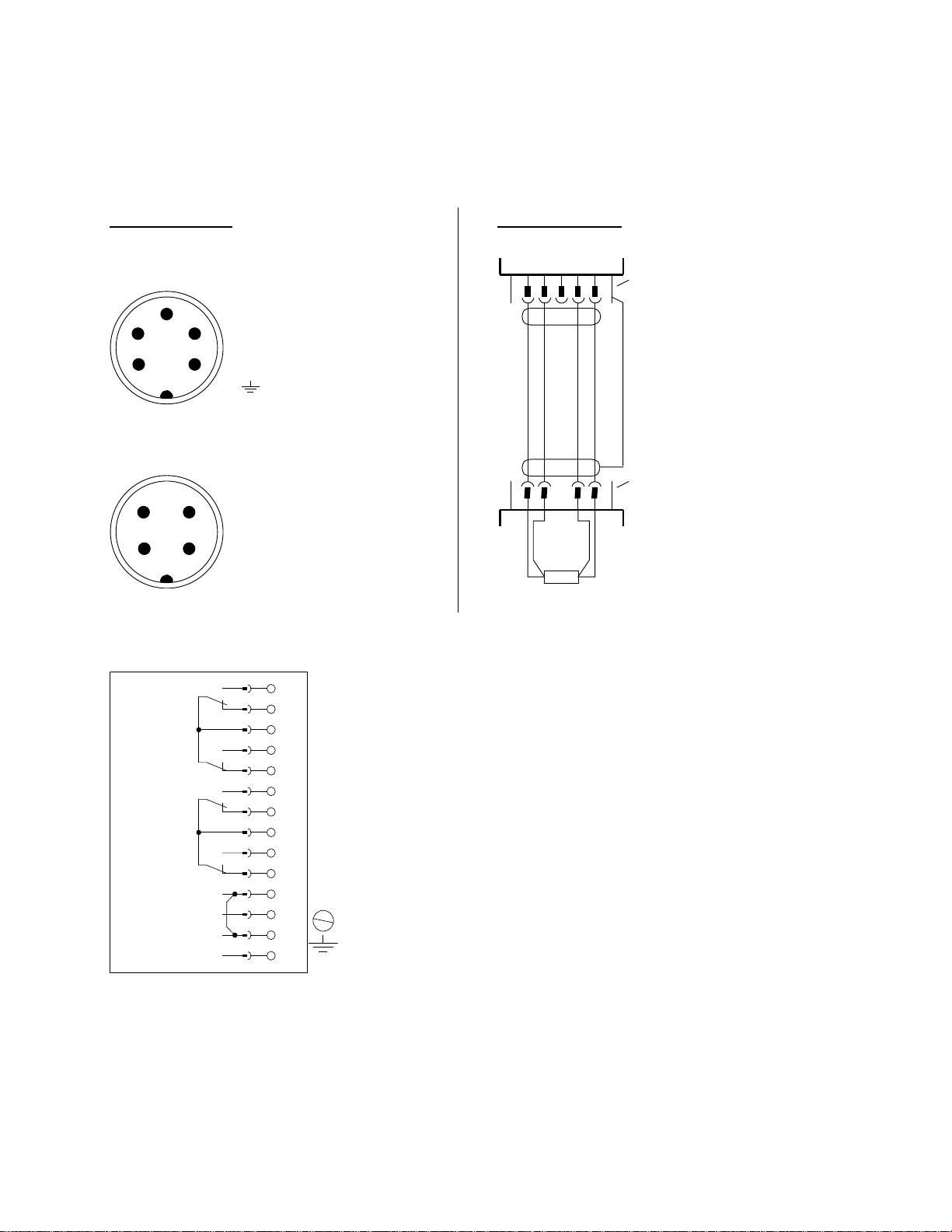
Pin connection
Wiring diagram
Intern al view of pin connect ions (on the ET S 1700)
5-pole Binder connect or, series 723
1 2 3 4 5
Pin 1
= + supply
Pin 2
3
4
5
2
1
= + signal
Pin 3
= reserved
Pin 4
= - signal
Pin 5
= - supply
= plug housi ng for
screen
Intern al view of pin connections (on the TFP 100)
4-pole Binder connector, series 714
1 2 3 4
2 3
1
Pin 1
= + supply
Pin 2
= + signal
Pin 3
= - signal
Pin 4
4
= - supply
3.2 Relay outputs, analogue output, supply voltage
Relay 4
= Switching point 4
Relay 3
= Switching point 3
Relay 2
= Switching point 2
Relay 1
= Switching point 1
Analogue output (0 V)
Analog ue o utput (signal +)
Supply (0 V)
Supply (+ UB)
14
13
12
11
10
9
8
7
6
5
4
PE
3
2
1
Sensor
resistance
ETS 1 70 0
5-pole
Binder conn ector ,
series 723
screened
connection line
4-pole Binder
connector, series
714
TFP 100
4. Operating keys on the membrane keypad
Page 3

HYDAC ETS 1700
undo screws
to remove
operating panel
°C
ON
ON
m
o
d
e
OFF
SP1
OFF
SP2
r
e
s
e
t
ON
OFF
SP3
ON
m
a
x
OFF
+
_
SP4
4-digit
digital display
keys for setting the switching points
and additional fun c tions
5. Digital display
After switching on the supply voltage, the unit briefly displays ”ETS” and then displays the
current temperature.
2 s
Notes:
• In the basic settings the display can be altered so that, once switched on, the unit displays a
switching point or the maximum value permanently. In this case ”S.P. 1”, ”S.P. 2”, ”S.P. 3”,
”S.P. 4”, or ”MAX” appears briefly on the display following the switch-on message. The
current temperature can be displayed briefly by pressing the ”+” or ”-” key.
• If the current temperature exceeds the nominal temperature of the unit, it can no longer be
displayed and the display begins to flash.
• If the current temperature is below 0.5 °C, then 0 is displayed.
6. Output function
6.1 Relay outputs
The ETS 1700 has 4 relay outputs. One switching point and one switch-back point and/or one
hysteresis can be set for each relay. The appropriate relay pulls in when the pre-set switching
point is reached and drops back when the temperature falls below the switch-back point.
Whether the unit operates with adjustable hystereses or adjustable switch-back points is
determined via the ”switch-back mode”, in the basic settings (see Point 8).
Switch-back mode is set to "hysteresis":
The pre-set hysteresis determines the switch-back point (switch-back point = switching point
minus hysteresis).
Switch-back mode is set to ”switch-back point”:
The switch-back point is set directly.
Page 4

Abbreviations: "S.P.1" .. "S.P.4" = switching points 1..4
"HYS.1" .. "HYS.4" = hystereses 1..4
"r.S.P.1" .. "r.S.P.4" = switch-back points 1..4
6.2 Analogue output
Analogue output signal 4..20 mA or 0..10 V (adjustable in the "Basic setting" menu)
Page 5
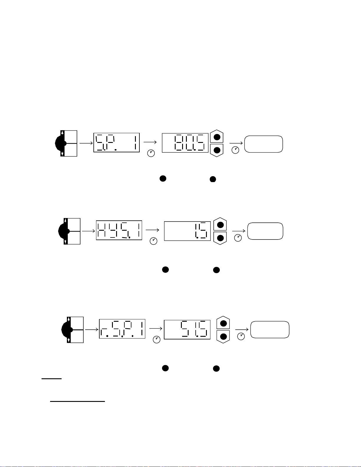
6.3 Setting the switching points and switch-back points / hystereses
• Press appropriate key
• Switching point/switch-back point/hysteresis number is displayed e.g. "S.P. 1"
• After 2 seconds the current setting flashes.
• Using the "+" and "-" keys, alter the setting.
• After 3 seconds the display switches back..
6.3.1 Setting a switching point
+ +
ON
m
o
d
e
OFF
SP1
press ON key display set swi tching point
6.3.2 Setting a hysteresis
(Only possible if the switch-back mode is set to ”hysteresis”.)
2 s
= lar ger valu e
+
+
_
3 s
_
= smaller value
temperature
display
ON
m
o
d
e
OFF
SP1
*
press OFF key
6.3.3 Setting a switch-back point
(Only possible if the switch-back mode is set to ”switch-back point”.)
ON
m
o
d
e
OFF
SP1
display
2 s
2 s
set hystere sis
= lar ger valu e
+
*
press OFF key display set switch-back point
= lar ger valu e
+
Notes:
+
+
_
3 s
_
= smaller value
+
+
_
3 s
_
= smaller value
temperature
display
temperature
display
• If ”LOC” appears in the display when trying to alter the settings, programming is disabled.
Corrective action: set hardware and software programming enable to ”ON”. (See Point 9
"Programming enable")
• If the ”+” or ”-” key is held down during alteration, the value automatically advances in larger
increments.
• If a setting has been altered, ”PROG” appears briefly in the display when the display switches
over. The new setting is then saved in the unit.
Page 6

7. Maximum value
The maximum value is the highest temperature value that has occurred since the unit was
switched on or since the last re-set.
7.1 Displaying the MAX value
+
ON
m
a
x
OFF
*
SP4
2 s
temperature
display
5 s
press ON and
OFF keys of
switching point 4
simultaneously
7.1 Re-setting the MAX value
display
+
ON
r
e
s
e
t
OFF
SP3
*
press ON and
OFF keys of
switching point 3
simultaneously
display maximum value
maximum valu e
is displayed
temperature
display
2 s
is re-set
Page 7

8. Basic settings
In order to adapt the unit to the particular application, the function of the ETS 1700 can be
altered via several basic settings. These are combined in one menu.
8.1 Altering the basic settings
+
+
_
m
+
ON
o
d
e
OFF
SP1
2 s
m
o
d
e
ON
OFF
SP1
+
2 s
*
display press ON and
OFF keys of
switching point 1
simultaneously
To close the basic setting menu:
Call up the menu point END, set to YES, the ETS 1700 returns to the normal display mode after
2s.
Or:
Press ON and OFF keys of switching point 1 simultaneously, END is displayed, the ETS 1700
returns to normal display mode after 2s.
Notes:
• If ”HIDE” is displayed instead of ”MENU”, the menu can only be called up if the keys are held
down when the supply voltage is switched on (see Point 8.2 ”Summary of basic settings,
Hidden basic setting menu”)
• When changing the display range, the switching point and hysteresis or switch-back point
settings are converted automatically. This can cause minor rounding errors.
• If after 50 seconds no keys have been pressed, the menu automatically closes down. Any
changes which may have been made will not be saved.
select menu point using single
key. (ON for next,
OFF for previous menu point)
alter setting,
then select next
menu point
Page 8

8.2 Summary of the basic settings
Setting Display Setting
range
Switching direction relay 1 (Relay 1)
”ON”: The relevant relay is activated when the
switching point is reached, and deactivated
when the temperature falls below the switchback point.
”OFF”: The relevant relay is activated in the
quiescent state (0 °C / 32 °F), and deactivated
when the switching point is reached.
Switch-on delay relay 1 (T
Time in seconds which must elapse, once the
particular switching point has been reached or
exceeded, before switching will occur.
Switch-off delay relay 1 (T
Time in seconds which must elapse, once the
temperature has fallen below the particular switchback point, before switching will occur.
:
Relays 2..4 as above
on
off
1)
1)
ON/ OFF ON
0..900s 0.1
0..900s 0.1
Presetting
Switch-back mode (Switch Mode)
”R.S.P”: The ETS 1700 operates with adjustable
switch-back points.
”HYST”: The ETS 1700 operates with adjustable
hystereses.
(see also point 6.1 "Relay outputs”)
Primary display (Primary)
Display value which should remain permanently in the
display:
”ACT.”: current temperature
”S.P.1” .. ”S.P.4”: switching point 1..4
”MAX”: maximum value
Determining the display range (RANGE)
”°C”: The temperature is displayed in °C.
”°F”: The temperature is displayed in °F.
“FREE”: The display range can be defined by the
user. If this setting is selected, then
decimal places and upper and lower
display range must be set. (see below)
R.S.P./
HYST.
ACT/
S.P.1 ..
S.P.4/
MAX
°C/ °F /
FREE
HYST.
ACT.
°C
Display the unit (Unit)
If set to ”YES” the pre-set unit will be displayed briefly
every 7 seconds.
YES/ NO NO
Page 9

Decimal places (Point)
(only when set to “RANG”=“FREE”)
Number of decimal places which the ETS 1700
displays.
0 ..
0.000
0.0
Lower display range (Range Low)
(only when set to “RANG”=“FREE”)
Lower display range limit
Upper display range (Range High)
(only when set to “RANG”=“FREE”)
Upper display range limit
Analogue output (Output)
”MAMP”:The analogue output supplies a 4..20 mA
signal
”VOLT”: The analogue output supplies a 0..10 V
signal
Hidden basic settings menu (Hide)
”YES”: The basic settings menu is hidden and can
only be accessed if the keys for calling up
the menu are held down when the supply
voltage is switched on.
Version number (Version)
Display of the current software version (for reference
only)
-995 ..
9995
-995 ..
9995
MAMP/
VOLT
YES/ NO NO
0.0
measuring range
final value
VOLT
To end basic settings (End)
YES/ NO
9. Programming enable
The unit has 2 types of programming enable which must both be set to ”ON” to change the
settings. The software programming enable can be set or removed during operation. It provides
protection from unintentional alteration. A programming disable via the hardware programming
enable means that no change to the settings can be carried out during operation. This serves,
for example, as a safety function or as protection against unauthorised alterations.
9.1 Altering the software programming enable
Page 10

+
F
g
_
*
+
3 s
2 s
+
_
+
temperature
display
3 s
display press both keys
simultaneously and
hold down for 3s
alter setting using individual key:
ON
OF
= programming possible
ramming disabled
= pro
9.2 Altering the hardware programming enable
• Disconnect the unit from the supply voltage.
• Remove the 4 screws from the unit front panel (Figure 1).
• Lift front panel off carefully and put to one side.
• Push slide switch on the lower board to the required position (Figure 2):
"OFF”: programming disabled
• Replace front panel on the unit and screw into position, ensuring that the front panel seal is in
the correct position.
programming
possible
HYDAC ETS 1700
°C
ON
ON
ON
m
o
d
e
OFF
SP1
r
m
e
a
s
x
e
t
OFF
OFF
SP2
SP3
+
ON
_
OFF
SP4
disabled
off
off
Figure 1
Figure 2
10. Altering the mounting position
• Disconnect the unit from the supply voltage.
• Remove the 4 screws from the front plate of the unit (Figure 1).
• Carefully lift off the front panel and turn through 180°.
• Replace the front panel on the unit and screw into position, ensuring that the front panel seal
is in the correct position (Figure 2).
Page 11

HYDAC ETS 1700
°C
ON
ON
m
o
d
e
OFF
OFF
SP1
SP2
ON
ON
r
e
s
e
t
OFF
SP3
+
m
a
x
_
OFF
SP4
sensor connection
sensor connection
HYDAC ETS 1700
°C
ON
ON
m
o
d
e
OFF
OFF
SP1
SP2
ON
ON
r
e
s
e
t
OFF
SP3
+
m
a
x
_
OFF
SP4
Figure 1
Figure 2
Page 12

11. Error messages
If an error is detected, then a corresponding error message appears which must be
acknowledged by pressing any key. Possible error messages are as follows:
ER.01 The switching points and hystereses/switch-back points are not within the
permissible setting range.
Corrective
action: Correct the settings.
ER.10 A data error has been detected in the saved settings. Possible causes are strong
electromagnetic interference or a component fault.
Corrective
action: Check all the settings (programming enable, switching points, switch-back points
and basic settings) and correct these if necessary. If the error occurs frequently,
please contact our Customer Service Department.
ER.12 An error has been detected in the stored calibration data. Possible causes are
strong electromagnetic interference or a component fault.
Corrective
action: After acknowledging the error, the unit will continue to operate, with reduced
accuracy, until it is switched off. However, check all important settings (switching
points, switch-back points and basic settings) and correct these if necessary. The
unit must in any case be returned to the manufacturer for re-calibration or repair.
An error has been detected in the stored calibration data. Possible causes are
strong electromagnetic interference or a component fault.
Corrective
action: Check the supply voltage to the ETS 1700
Page 13

12. Technical specifications
Input data:
Measuring ranges: 0 .. 100 °C / 32 .. 212 °F
Output data:
Accuracy (display, analogue output)
Repeatability:
Temperature drift in the ambient temperature
range:
Analogue output:
Signal:
Switching outputs:
Type: 4 relays with change-over contacts in 2
Switching voltage: 0.1 .. 250 VAC / VDC
Switching current: 0.009 .. 2 A
Switching capacity: 400 VA, 50 W
Life expectancy of contacts:
Reaction time (without switching delay): approx. 20 ms
Setting range of switching points 1.5 .. 100 % of the measuring range
Setting range of hystereses / switch-back
points
Ambient conditions:
Ambient temperature range: -25 .. +60 °C / -13 .. +140 °F
Storage temperature range: -40 .. +80 °C / -40 .. +176 °F
:
mark
Vibration resistance: approx. 5 g
Shock resistance: approx. 10 g
Other data:
Sensor connection: 5-pole Binder connector, series 681
≤ ±1.0 % of the measuring range
≤ ±0.25 % of the measuring range
≤ ±0.03 %/°C / ≤ ±0.054 %/°F zero point
≤ ±0.03 %/°C / ≤ ±0.054 %/°F range
4 .. 20 mA, ohmic resistance ≤ 400 Ω
0 .. 10 V, ohmic resistance ≥ 2 KΩ
groups (common supply of each group
connected)
(for inductive load, use varistors)
≥ 20 million min. load
≥ 1 million max. load
1 .. 99 % of the measuring range
EN 50081-1, EN 50081-2
EN 50082-1, EN 50082-2
Electrical connection: 14-pole, terminal strip,
connection cross-section max. 1.5 mm²
Supply voltage:
Current consumption: approx. 200 mA
Display: 4-digit 7-segment LED display, red,
Safety type: IP 65
Weight: approx. 800 g
Technical specifications - Accessories
TFP 100
Temperature range of medium (for TFP 100): -40 .. +125 °C / -40 .. +257°F
22 .. 32 VDC, residual ripple ≤10%
height of digits 13 mm
Page 14

Safety sleeve for tank mounting the
TFP 100
Parts in contact with fluid: All materials compatible with nickel
13. Model code
0X - 100 - 000ETS 1 7
Type of sensor
0 = for PT 100 sensors
(Sensor TFP 100 must be ordered separately, see below)
Display
1 = 4-digit °C
2 = 4-digit °F
Measuring range
100 = 0 .. 100 °C / 32 .. 212 °F
Modification number
000 = standard (determined by manufacturer)
14. Accessories
14.1 Accessories supplied with the unit
• PG 11 cable glands
• 4 mounting screws M5 x 20 mm
• 5-pole Binder connector, series 681
• 3 m connection line for TFP 100 (LIYCY 4x0.25 mm²)
14.2 Other accessories
(must be ordered separately)
• Temperature sensor TFP 100 (ZBE 03 plug included)
• Safety sleeve for tank mounting
• Mounting kit ( 4 vibration mounts, 4 screws M5 x 6 mm)
Page 15

15. Dimensions
countersunk DIN74-Km5
connection line LIYCY (3m long)
cable glant PG11
5 pole Binder connector
series 681
ZBE 03 plug
safety sleeve
TFP-100 (temp. sensor)
hex-SW27
 Loading...