

Page 1
Elektronischer Druckschalter
Electronic Pressure Switch
Manocontacteur électronique
EDS 601
Benutzerhandbuch
Operating Manual
Manuel d'utilisation
Page 2

E
CONTENTS
1. General
1.1. Features
1.2. Installation options
1.3. Settings
1.4. Warranty
1.5. Queries and problems
2. Installation
2.1. Installed as pressure gauge
2.2. Installed as front panel measuring unit
2.3. Making the electrical connection
2.4. Supply voltage
2.5. Dimensions
2.6. Pin connections
2.7. Connection examples analogue output
3. Operation
3.1. Overview
3.2. Setting the switching points
3.3. Basic settings
3.4. Altering the measuring range
3.5. Altering the calibration
3.6. Disabling the programming
4. Error messages
4.1. Operating errors
4.2. Data errors
4.3. Invalid operating conditions
5. Technical data
6. Appendix A: Menu hierarchy
7. Appendix B: Parameter form sheet
8. Appendix C: Application example
Page 3

General
1.
Features
1.1.
l built-in pressure sensor with steel membrane
l 4-digit, 7-segment display to show the current pressure
l analogue output, switchable 0..10 V or 4..20 mA as current source
l two individually adjustable switching relays with change-over contacts
1.2.
Installation options
l directly into the system using a G ¼ threaded connection,
or via a mechanical adapter into a G ½ pressure gauge connection
to DIN 16288
l as a front panel unit where the connection is made via a hydraulic hose
Settings
1.3.
Switching point settings:
l Switching point and switching hysteresis relay 1 and relay 2
Basic settings:
l Switching direction relay 1 and relay 2
l Switching delay relay 1 and relay 2
l Switch-back delay relay 1 and relay 2
l Measured value filter on the display value
l Standard display value (current pressure, switching point or peak value)
l Analogue output signal (0..10 V or 4..20 mA)
Measuring range settings:
l Upper and lower measuring range limit
Calibration options:
l Re-calibration of the internal sensor for both zero and final value settings
l Re-calibration of the signal range of the analogue output
Warranty
1.4.
Both the components of the EDS 601 and the complete unit are subject to
stringent quality controls. Each EDS 601 is individually calibrated and subjected
to a final test. In this way we can guarantee that the unit is fault-free on despatch
and conforms to the given specifications. However, if there is cause for
complaint, please return the pressure switch to us outlining the fault.
Interference by anybody other than Hydac personnel will invalidate all warranty
claims.
Queries and problems
1.5.
If you have any queries regarding technical details or the suitability of the
pressure switch for your application, please contact our sales/technical
department. The EDS 601 pressure switches are maintenance-free and should
operate perfectly when used according to the specifications
(see Technical Data). If faults do nonetheless arise, please contact the
Electronics Servicenter.
E
FLUPAC LIMITED
Technical sales
Tel.: 01608 / 81 12 11
Fax: 01608 / 81 12 59
Page 4

E
Installation
2.
Installed as pressure gauge
2.1.
The EDS 601 can be installed directly into the hydraulic system via the G ¼
threaded connection or an adapter. Depending on the type of connection, the
sealing should be to DIN 3852 or DIN 16288. The torque should be within the
range 20..30 Nm. (Where adapted for G½: 45..50 Nm).
Installed as front panel measuring unit
2.2.
The unit is installed in a front panel cut-out of 68.5 x 68.5 mm. The unit is
secured with clamps from the mounting set, which can be ordered separately.
For mechanical de-coupling the hydraulic connection must be via a standard
small bore instrument hose. The sealing can be by means of an O-ring or a
metallic soft seal to DIN 3852. The torque should be within the range 20..30 Nm.
Note: When installed as a front panel unit a rigid hydraulic connection
G
Making the electrical connection
2.3.
The electrical connection should be carried out by a qualified electrician
according to the relevant regulations of the country concerned (VDE 0100 in
Germany).
The electronic pressure switches EDS 601 carry the mark. A declaration of
conformity is available on request.
The EMC-standards EN 50081-1, EN 50081-2, EN 50082-1 and EN 50082-2
apply.
The requirements of the standards are fulfilled only if the pressure switch
housing is earthed correctly by qualified personnel. If the pressure switch is
mounted inline, it is sufficient if the pipe is earthed via the hydraulic system. In
the case of hose-mounting, the housing must be earthed separately via the PE
connection of the 4-pole plug.
Additional assembly notes which, from experience, reduce the effect of
electromagnetic interference:
l Make line connections as short as possible.
l Use screened lines (e.g. LIYCY 4 x 0.5 mm
l The cable screening must be fitted by qualified personnel subject to the
l Direct proximity to connecting lines of user units or electrical or electronic
must not be used.
2
).
ambient conditions and with the aim of suppressing interference.
units causing interference must be avoided as far as possible.
Page 5
E
2.4.
Supply voltage
The EDS 601 switches on automatically as soon as sufficient supply voltage is
available. If, however, the supply voltage afterwards falls so low that reliable
operation can no longer be guaranteed, "- - - - appears in the display and the
relays and the analogue output are switched off. As soon as sufficient voltage is
once more available the unit operates again automatically. If the voltage sinks so
low that operation is no longer possible at all, the unit switches itself off
completely.
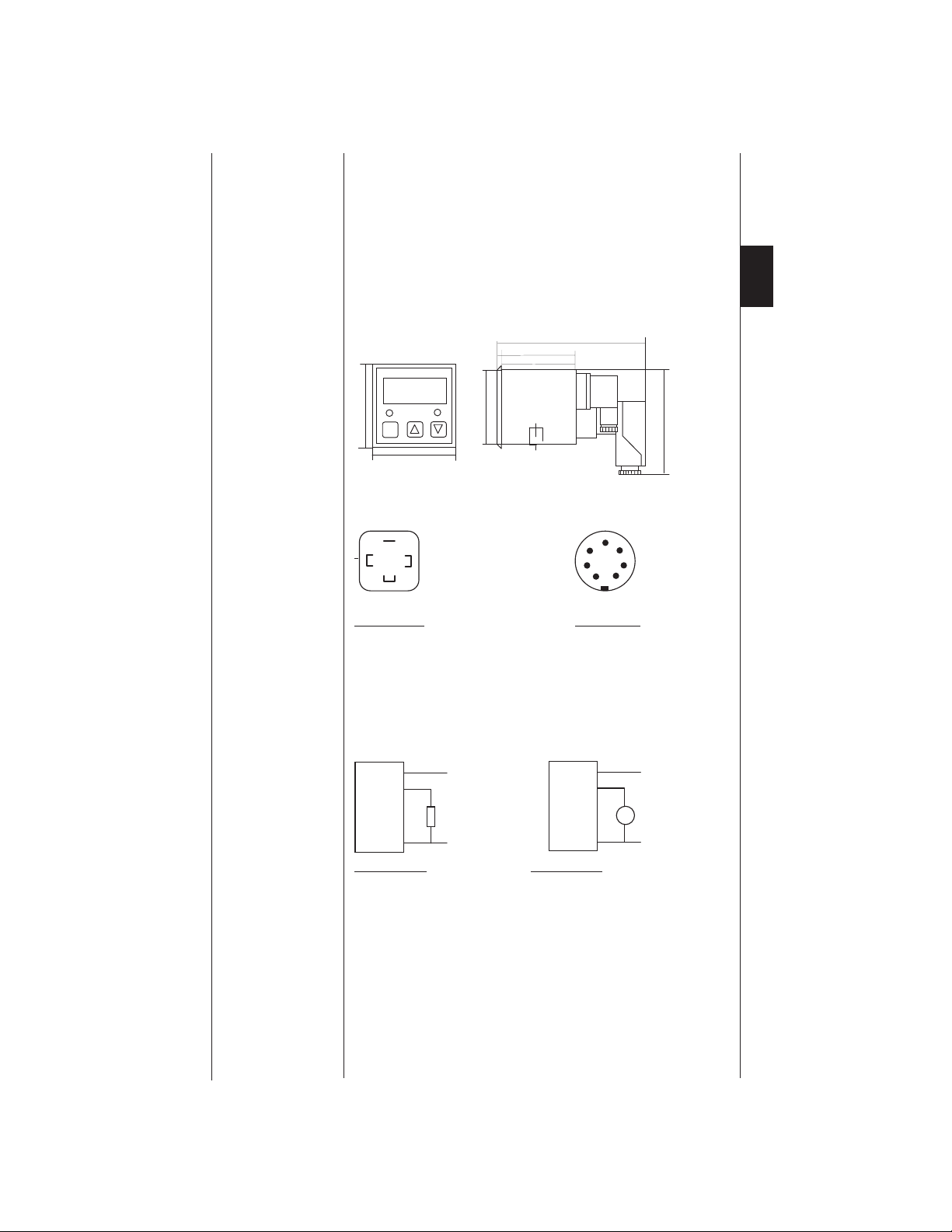
Dimensions
2.5.
164
98,7
83,5
E
2.6.
72
SP1 SP2
Prog
72
Pin connections
PE
1
2
3
67
G1/4"
PE
1
2
3
4
Voltage supply Relay outputs
Plug to DIN 43650 / IEC 4400 plug to DIN 43651
Pin 1: 24V Pin 1: relay 1 N/C contact
Pin 2: 0V Pin 2: relay 1 N/O contact
Pin 3: analogue output Pin 3: relay 1 common supply
Pin 4: relay 2 N/C contact
Pin 5: relay 2 N/O contact
Pin 6: relay 2 common supply
2.7.
Connection examples analogue output
EDS 601
1
24 V
3
Signal
R
L
2
0 V
EDS 601
1
3
2
Current output: Voltage output:
max. load resistance 400 W min. load resistance 2 kW
100,5
6
5
24 V
Signal
V
0 V
Page 6

E
3.
Operation
Overview
3.1.
The EDS 601 pressure switch is designed so that all standard applications are
covered with very little effort and the secondary operating options provide for a
high level of functionality.
When the supply voltage is switched on the unit displays the current pressure,
the relays switch in accordance with the set switching points and the analogue
signal is available. If the measured value is below the accuracy limit of 1 % the
lower measuring range limit (i.e. 0) is always displayed. If the measured value
exceeds or falls below the evaluation range of the pressure switch, either "O.P.
(Over Pressure) or "U.P. (Under Pressure) is displayed. The switching points
and switching hystereses of both relays can be set using the PROG, D and Ñ
keys. The switching hysteresis establishes by how many bar the value has to
fall below the switching point before the relay switches back again. This is the
standard use of the EDS 601.
In a secondary "Basic menu the following settings can be altered:
l To prevent switching during short-term pressure changes, the switching
delay and switch-back delay for each relay can be set within the range 0.00
to 90.00 s.
l The switching direction can be set for each relay. This allows the user to
determine whether the relay pulls in or drops when the switching point is
reached.
l The primary display can be altered to determine if the EDS 601 displays
the current pressure, either of the set switching points or the pressure
peak value. The pressure peak value is the highest pressure value that has
occurred since the unit was last reset. The unit is reset via the keyboard or
when the unit is switched on.
l In order to steady the displayed value an adjustable filter can be used to
smooth slight pressure deviations in the display.
l The analogue output signal can be converted from current to voltage. It is
switched between 4..20 mA and 0..10 V as standard.
For all applications where the measuring range is not required in bar, the
measuring range can be altered in a "Measuring range menu. This allows the
range to be displayed in bar, psi, MPa, kg, Nm, to name but a few. It is also
possible to specifically adjust the limits for an offset. (Please see point 3.4)
The EDS 601 also has a "Calibration menu. This allows the user at any time to
calibrate the built-in sensor in the zero point and the final value, the analogue
output in the zero point and the final value and to attain other output signal
ranges (e.g. 1..5 V, 0..20 mA, ...). To prevent accidental re-programming of the
settings, the programming can be disabled.
The appendix gives an overview of the menu hierarchy as well as a parameter
form sheet to assist with the setting of the EDS 601.
Page 7

3.2. Setting the switching points
To set the switching points, press the PROG key. "S.P.1 appears in the display
and shortly afterwards the value of switching point 1 begins to flash. The D and
Ñ keys increase or decrease the displayed value. If the D or Ñ key is held
down the value is automatically advanced. After 10 automatic advances the
speed is increased so that even values that are far removed from the initial
values can be reached quickly. If PROG is pressed again "HYS.1 is displayed
and shortly afterwards the value of switching hysteresis 1. This value can now
be altered in the same way as described above. Further pressing of the PROG
key then allows selection of switching point 2 and switching hysteresis 2.
Exiting the switching point setting:
If no key has been pressed for approx. 3 seconds the EDS 601 reverts to the
normal display. If any settings have been altered the new settings are
programmed into an internal memory and are saved even after the unit has
been switched off. "PROG appears for a short time in the display before the
unit reverts to the normal display.
Invalid settings:
If the switching hysteresis is larger than the corresponding switching point, the
error message "Er.01 (Error No. 1) is displayed. This error message can be
acknowledged by pressing any key. Then the invalid switching point is displayed
and can then be corrected.
The values are not saved in the memory and the unit does not revert to the
normal display (primary display) until all the settings are valid.
Notes:
l The switching points can be set from 1..100 % of the measuring range, the
switching hystereses from 0.5..99.5 % of the measuring range. The setting
is carried out in steps of 0.5 bar, on measuring ranges below 100 bar in
steps of 0.05 bar.
l While the switching points/switching hystereses are being altered the
relays are switched according to the previous settings. The unit only
operates with the altered settings after it has reverted to the normal display.
l The individual menu options (S.P.1, HYS.1, S.P.2, HYS.2) can also
be selected by pressing the D key or the Ñ key whilst holding down the
PROGkey.
Basic settings
3.3
Basic settings are settings that are altered only very rarely, usually only when
the unit is first installed. The following table shows the available settings and
the manufacturers pre-setting.
E
Settings Display Settings available Pre-setting
Switching direction relay 1 REL.1 on/off on
Switching delay relay 1 T.ON.1 0.0..90 s 0.01
Switch-back delay relay 1 T.OF.1 0.0..90 s 0,01
Switching direction relay 2 REL.2 on/off on
Switching delay relay 2 T.ON.2 0.0..90 s 0.01
Switch-back delay relay 2 T.OF.2 0.0..90 s 0.01
Primary display PRIM. act./S.P.1/S.P.2/Top act.
Display filter DISP. fast/med./slow med.
Analogue output signal OUTP. M.Amp./Volt Volt
Display of software version VERS. installed version
Exiting the basic setting END. yes/no
Page 8

E
If the manufacturers pre-settings suit your application you can skip this chapter.
Altering the basic settings:
If the EDS 601 is showing the normal display, "S.P.1 appears when the PROG
key is pressed. If the key is held down for 5 seconds the word "BASE begins
to flash in the display. If the key is now released the unit returns to normal
operation. However, if it is held down for a further 5 seconds when the PROG
key is released the flashing stops and "REL.1, the first option under the basic
settings, appears in the display. The pre-set switching direction ("ON or "OFF)
begins to flash in the display and can be altered using the D or Ñ key. The
PROG key is used to alter the other basic settings. The setting is carried out as
described under "Setting the switching points.
Exiting the basic setting:
If no key is pressed for approx. half a minute the new settings are stored in an
internal memory and are saved even after the unit has been switched off.
"PROG appears briefly in the display and the current pressure is displayed
again (or the programmed primary display value).
A faster way of exiting the basic setting is to select option "END, set it to "YES
and press the PROG key.
Notes:
l The switching direction "ON means that the relay switches to the active
condition when the switching point is reached (relay pulls in, N/O contact
closes), and switches back to the inactive condition when the value falls
below the switch-back point (switching point - switching hysteresis) (relay
drops, N/O contact opens). "OFF means that the relay switches to the
inactive condition when the switching point is reached, i.e. the reverse of
"ON.
l The switching delay "T.ON operates when the switching point is reached
and the switch-back delay "T.OFF operates when the value falls below the
switch-back point (switching point - switching hysteresis) regardless of the
set switching direction.
l The set delay times refer only to the amount of time by which the value
must exceed or fall below the particular switching point in order for a
switching operation to take place. In addition, the reaction time of the unit
(sensor, electronics and relays) of approx. 10 ms must be taken into
account.
l So that the delay times can be altered quickly the setting is carried out in
various steps:
Range Steps
0 ms ..... 100 ms 10 ms
100 ms .... 1 s 50 ms
1 s ........... 10 s 0.5 s
10 s ......... 90 s 5 s
l When setting the primary display, "ACT means current pressure, "S.P.1
means value of switching point 1, "S.P.2 means value of switching point 2
and "TOP means peak value.
l If the primary display is set to "S.P.1 or "S.P.2, during normal operation
the EDS 601 displays the value of the switching point concerned. Here, the
current pressure can be displayed using the D or Ñ key. This remains in
the display until the key is released. As an indication, the number of the
particular switching point ("S.P.1 or "S.P.2) is briefly displayed when the
unit is switched on.
l If the primary display is set to "TOP, during normal operation the EDS
601 displays the peak value. This can be reset using the D or Ñ key. Then
"RES (RESET) appears briefly in the display. If the key is held down, the
current peak value is reset to the current display value. As an indication,
"TOP appears briefly in the display when the unit is switched on and the
peak value is automatically reset.
Page 9

l Altering the setting of the display filter affects the interval in which the
displayed value is renewed.
"FAST - renews the display value every 0.2 seconds.
"MED - renews the display value every 0.33 seconds.
"SLOW - renews the display value every 0.66 seconds.
The setting of the display filter does not affect the reaction time of the relay
outputs or the analogue output, but merely serves to steady the display in
the event of rapid pressure fluctuations.
l The software version can only be viewed, not altered. The display serves
as a means of identifying the unit version in the event of queries.
Altering the measuring range
3.4.
Please note: Altering the measuring range merely means that another
G
Example: If the measuring range of an EDS 601-250-000 (nominal
To alter the measuring range follow the same procedure as for the basic
settings, but do not release the PROG key when "BASE stops flashing, only
when "RANG stops flashing.
The measuring range has three settings:
1. The number of decimal places ("POIN.)
2. The lower measuring range limit ("RAN.L.)
3. The upper measuring range limit ("RAN.H.)
To select and alter the settings and to exit the setting follow the procedure
outlined in the "Basic settings chapter. If the measuring range is changed so
much that the set switching points or switching hystereses are now outside the
new range, they are automatically set to the standard setting (switching
hysteresis: 1 %, switching point 1: 50 % and switching point 2: 75 %). The error
message "ER.04 is displayed to indicate this.
3.5.
Altering the calibration
The EDS 601 can be calibrated at any time without opening the housing.The
calibration covers 3 areas:
l the sensor input
l the analogue output for the "Volt setting
scale is selected. The nominal pressure range of the
pressure switch always remains the same and must not be
exceeded.
pressure range 250 bar) is changed to 0 ... 738, the display
value of 738 corresponds to a pressure of 250 bar.
l the analogue output for the "M.Amp. setting
Note: The calibration menu should only be used by a qualified person.
G
To access the calibration menu all 3 keys must be held down as the unit is
switched on. After approx. 5 seconds "CALI. begins to flash in the display. After
a further 5 seconds the flashing stops. If the keys are now released the
calibration menu can now be used.
Calibrating the sensor input
When the menu option "AD.L is selected the current lower calibration value is
displayed for approx. 2 seconds followed by the current value of the A/D
converter. Set the pressure to the lower limit (i.e. 0 bar) and press the D or Ñ
key. If the value is within the permitted tolerance range "NEW is displayed. The
lower limit is now calibrated. Otherwise, "FAIL is displayed and the sensor will
not be calibrated.
The same applies for "AD.H with regard to the upper calibration value.
Calibrating the analogue output
The menu option "OUTP selects whether the output should be calibrated as
current output (setting "M.AMP) or voltage output (setting "VOLT). The D or Ñ
key can be used under option "DA.L and "DA.H to change the value of the
analogue output. The value can be "DA.L 0V or 4 mA and "DA.H 10 V or
20 mA.
Exiting the calibration
This menu is not exited automatically. To exit the calibration select option
"END, set it to "YES and press the PROG key.
Improper handling can lead to a loss of accuracy of the pressure
switch.
E
Page 10

E
Notes:
l The calibration should only be altered by a qualified person.
l Calibration is possible in the following ranges:
(All details in digits, based on 10 bit values = max. 1023)
Zero point Final value
Sensor 30 .. 120
digits
Output current 0 .. 300 digits 300 .. 1020 (10 digits 0.11
850 .. 1015
V)
l The zero point always refers to the lower measuring range limit, i.e. to the
pressure value 0 bar, not to the measured value 0. (The two are only
identical if the measuring range begins at 0).
l The signal range can be made compatible by specifically changing the zero
point and the final value of the analogue output, e.g. to 0..5 V, 1..5 V,
0..20 mA, 0..10 mA
l If the measuring range is not given in bar, incorrect measuring ranges can
arise due to the conversion, e.g., a 40 bar pressure switch which is
designed to be operated in the converted unit kN has a measuring range of
5.14 kN due to the conversion. By re-calibrating the unit it can be operated
as a 5 kN unit. For this purpose, change the measuring range to 5.00 and
calibrate the final value of the sensor to this value. This is especially
sensible when making use of the analogue output, as the 10 V signal now
corresponds to a value of 5.00 kN, no longer 5.14 kN.
Disabling the programming
3.6.
To prevent accidental re-programming of the settings, the programming can be
disabled. To enable or disable the programming the D and Ñ keys must be
pressed simultaneously. After approx. 5 seconds "PROG appears in the
display. Afterwards the condition of the programme disable is displayed and can
be changed with the D and Ñ keys.
l "ON means programming enabled
l "OFF means programming disabled
Once the PROG key has been pressed the condition of the programme enable
is saved in the memory and the unit reverts to the normal display (primary
display). If the programming is disabled ("PROG = "OFF) all the settings can
still be viewed but not altered.
»
»
4.
Error messages
4.1.
Operating errors
ER 01 Error when setting the switching points and switch-back hystereses.
ER 02 Error when setting the measuring range.
ER 03 Error when setting the calibration data.
ER 04 After the measuring range was altered the switching points or
4.2.
Data errors
For these errors to be understood, the following needs to be explained:
The settings with which the unit is operated are stored in a RAM. This memory
loses its contents, however, if the unit is no longer supplied with voltage. All
settings are stored in a second memory, an EEPROM. Whenever settings are
altered the data is written into the EEPROM from the RAM. When, however,
voltage is supplied they are then read back into the RAM from the EEPROM.
The switching hysteresis is either too large for the pre-set switching
point or the measuring range was altered so much that the
switching point lies outside the measuring range.
switching hystereses lay outside the new range and were
automatically corrected to the standard value by the EDS 601.
Page 11

For safety purposes, there are several means of recognising data errors in both
types of memory. The data in the EEPROM is checked during every read and
write operation, the data in the RAM is monitored cyclically. In environments of
strong electro-magnetic fields or when there are extreme surges in the supply
voltage, a data error can occur. However, if lots of errors occur external antiinterference measures must be taken. In individual cases, there may also be a
fault in the pressure switch.
To guarantee reliable operation, in cases of error a corresponding message is
displayed and the relays and the analogue output are switched off until the error
is acknowledged by pressing any key.
ER 10 An error was discovered when the EEPROM was used. Switch the
ER 11 Errors were discovered in the RAM. Please take appropriate anti-
ER 12 The calibration data has been lost. Until the unit is re-calibrated this
Invalid operating conditions
4.3.
The displays listed below are not error messages which need to be
acknowledged. As soon as the valid operating condition re-occurs the unit
operates normally.
unit off and on again. If error 10 still appears when the unit is
switched back on the data in the EEPROM is invalid. Please check
all settings (measuring range, basic settings, switching points,
calibration) and correct them if necessary. Then check whether the
settings are saved if the unit receives no supply voltage or if an error
message is still displayed when the unit is switched off and on again.
interference measures to guarantee reliable operation.
error will be displayed every time the unit is switched on.
l The display "- - - - means that the supply voltage has fallen so low that a
reliable operation of the pressure switch is no longer guaranteed. (see
chapter 2.4.). The relays and the analogue signal have been switched off.
l The display "U.P. (under pressure) means that the pressure in the system
is too low.
l The display "O.P. (over pressure) means that the measuring range of the
pressure switch has been exceeded so much that the pressure can no
longer be correctly measured.
E
Page 12

E
Technical data
5.
General data
Dimensions approx. 72 x 72 x 110 mm (W x H x D)
Housing material aluminium, an odised
Pressure ranges 16; 40; 100; 250; 400; 600 bar
Overload pressures 24; 60; 150; 375; 600; 900 bar
Burst pressure 300 % FS
Accuracy 1 % FS
Repeatability switching point 0.25 % FS typ.
Temperature range - 25...+ 70° C (-25...+ 85° C media temperature)
Temperature drift 0.5 %/10 K; typ 0.25 %/10 K FS
Safety type IP 65
Vibration resistance 25 g/0...500 Hz
Shock absorbency 50 g/ 1 ms
mark
Connection supply voltage plug to DIN 43650/ISO 4400 (3 pol. + earth)
Connection relays plug to DIN 43651 (6 pol. + PE)
Pressure connection G¼" female thread, sealing to DIN 3852
Supply voltage DC 20...32 V
Current consumption approx. 120 mA
Starting current approx. 1.5 A (0.1 s)
Display 7-segment LED display, 4 digits, 13 mm high
Signal output 0...10 V ohmic resistance: min. 2
Limit frequency signal output 20 Hz
Relay outputs
Number/function 2 relays with change-over contacts
Switching voltage 0.1...250 V
Switching current 0.025...2 A
Switching capacity 50 W/ 400 VA
Reaction time approx. 10 ms (sens or + electronics + relays)
Life expectancy of contacts 10 m ill. without load
£
£
£
EN 50081-1, EN 50081-2,
EN 50082-1, EN 50082-2
4...20 mA ohmic resistance m ax. 400
1 mill. at nominal load
kW
W
Note: FS (Full Scale) = relative to the full measuring range
Page 13

Appendix A: Menu hierarchy6.
E
Page 14

Appendix B: Parameter form sheet
7.
E
Switching point settings
Switching point 1 S.P.1
Switching hyster esis 1 HYS.1
Switching point 2 S.P.2
Switching hyster esis 2 HYS.2
Basic settings
Switching direction relay 1 REL. 1
Switching delay relay 1 T. ON.
Switch-back delay relay 1 T. OF.
Switching direction relay 2 REL. 2
Switching delay relay 2 T. ON.
Switch-back delay relay 2 T. OF.
Primary disp lay PRIM.
Display filter DISP.
1
1
2
2
Measuring range settings
Decimal point position POIN.
Lower measur ing range limit RAN.L.
Upper meas uring range limit RAN.H.
Notes
EDS 601
Serial number:
Date:
Installation site:
Note: Take a copy of this sheet and fill in your required settings. You can
keep this form sheet near your manual so that you can refer to the
particular setting options at the same time. Do not commence
programming of the EDS 601 until you are sure about all the
settings. This is especially important in the case of complex settings.
This sheet can also be used for documentation purposes.
Page 15

Appendix C: Application example
8.
Accumulator charging circuit:
When the system pressure is reached, relay 1 switches the pump into the
bypass. If the pressure falls by the value of the switching hysteresis, the pump
begins to feed to the system again. The switching direction of relay 1 was set to
"OFF and the N/O contact was used as the switching contact. This guarantees
that the pump is not operating if the EDS 601 is switched off.
Relay 2 switches a warning light which lights up when the system pressure is
too low. As it also needs to light up if the EDS 601 is switched off, the switching
direction of relay 2 was set to "ON and the N/C contact was used. To bridge
short-term pressure surges, the switch-back delay was programmed to
2 seconds.
For documentation purposes, the analogue output is also connected to a central
data acquisition unit (DAU).
E
20 .. 36 V
to DAU
Rel 2
Rel 1
UB
6
5
4
3
2
1
warning light
pressure- min.
0V
EDS 601
1
2
0V
3
 Loading...