

Page 1
Stand: 20.03.2018 HYDAC ELECTRONIC GMBH Mat. Nr.: 669736
Bedienungsanleitung
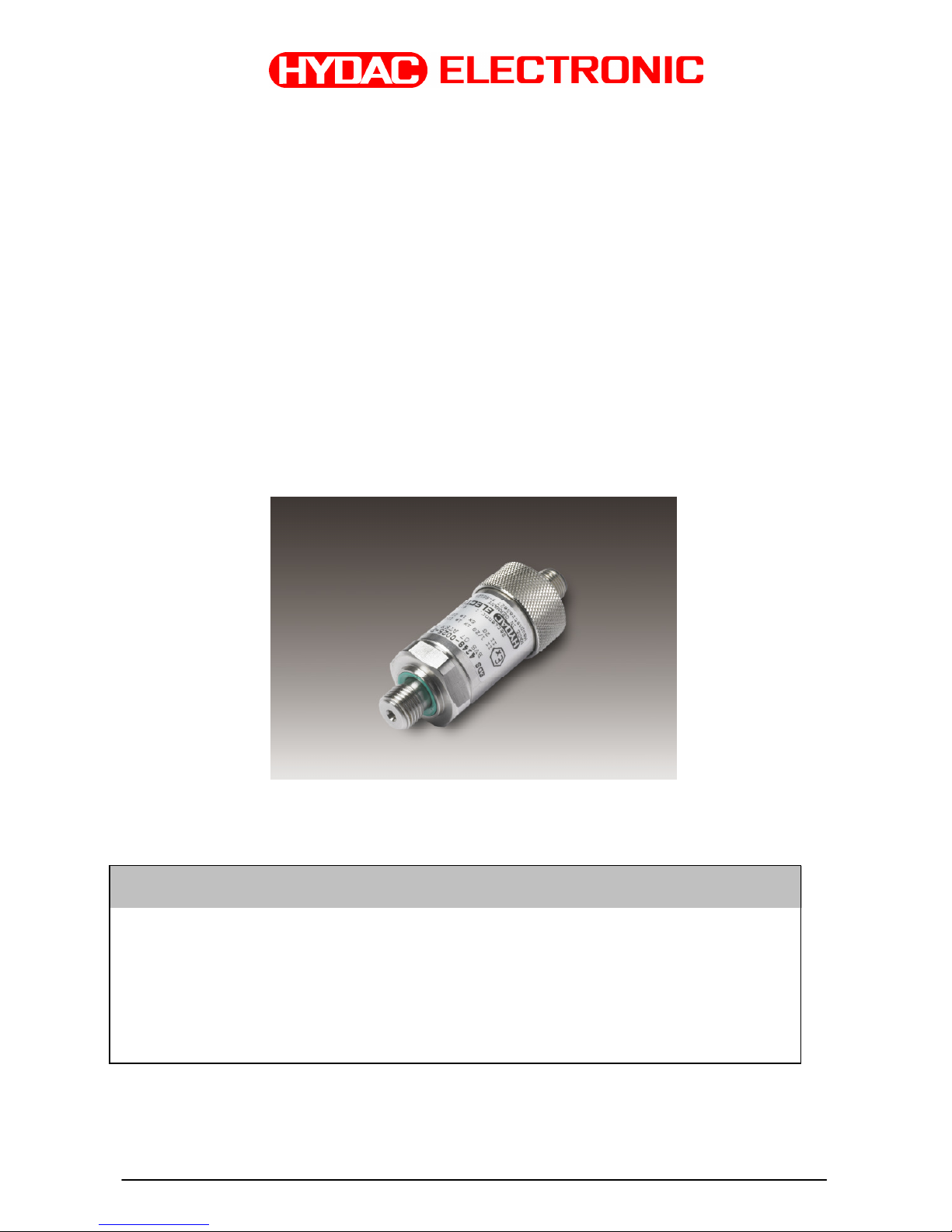
Druckschalter Serie EDS 4000
Eigensicher
ATEX- Zulassung
(Original-Bedienungsanleitung)
Operating Instructions
Pressure Switch Series EDS 4000
for Intrinsically Safe
ATEX- approval
(translation of the original instructions)
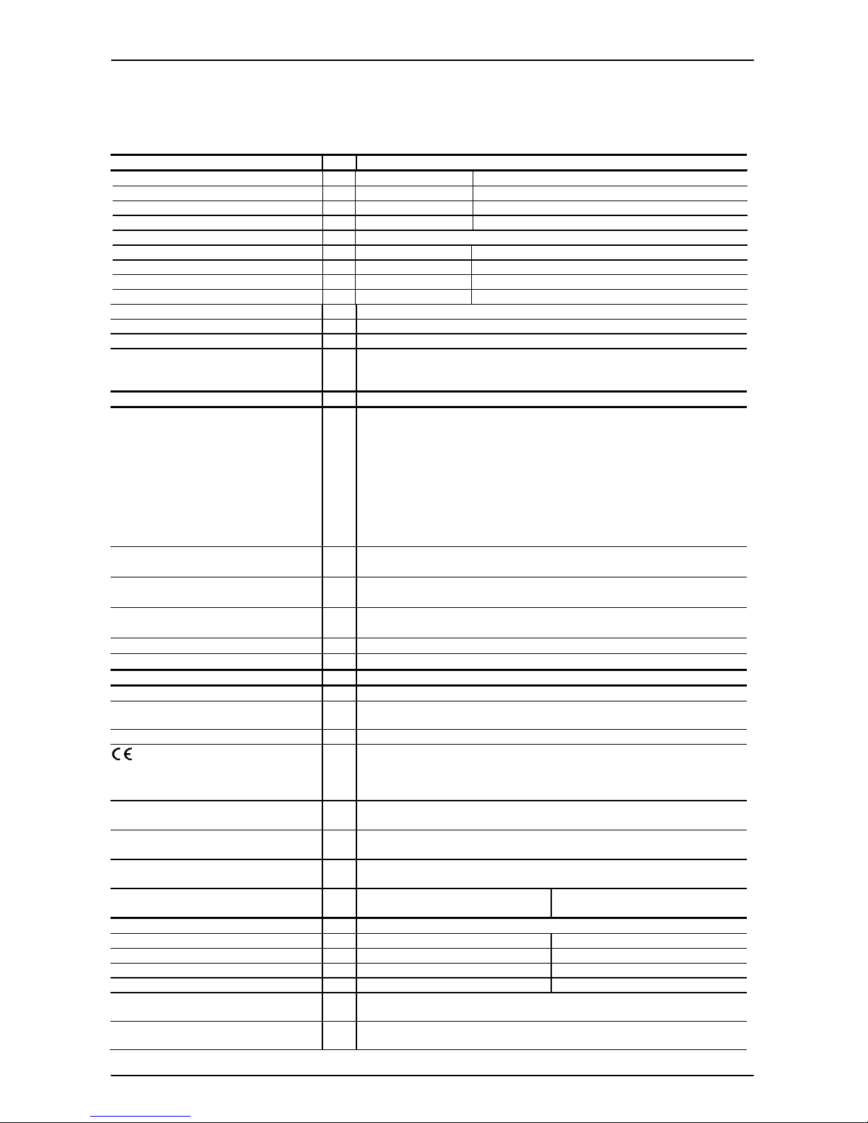
Schutzklassen und Einsatzbereiche / Protection types and zones:
ATEX
I M1 Ex ia I Ma
II 1G Ex ia IIC T4, T5, T6 Ga
II 1/2 G Ex ia IIC T4, T5, T6 Ga/Gb
II 2 G Ex ia IIC T4, T5, T6 Gb
II 1 D Ex ia IIIC T100°C Da
Bescheinigungsnummer/
Certificate no : BVS 07 ATEX E 041 X
Page 2

EDS 4000 mit ATEX-Zulassung Seite 2 von 26
Stand: 20.03.2018 HYDAC ELECTRONIC GMBH Mat. Nr.: 669736
Page 3

EDS 4000 mit ATEX-Zulassung Seite 3 von 26
Stand: 20.03.2018 HYDAC ELECTRONIC GMBH Mat. Nr.: 669736
Inhaltsverzeichnis
1. ALLGEMEINES ............................................................................................................... 4
2. FUNKTION ...................................................................................................................... 4
3. MONTAGE UND INBETRIEBNAHME ............................................................................ 4
4. WICHTIGE HINWEISE FÜR DIE CONDUIT-INSTALLATION ........................................ 5
5. SICHERHEITSHINWEISE ............................................................................................... 6
5.1 Bemerkungen zum Schaltausgang ............................................................................ 8
5.2 Sicherheitsbarrieren .................................................................................................... 8
5.3 Vorbereitende Überlegungen für die Auslegung eines Systems: ........................... 9
5.4 Berechnungsbeispiel: ............................................................................................... 10
6. TECHNISCHE DATEN .................................................................................................. 11
6.1 EDS 41xx / 43xx ......................................................................................................... 11
6.2 EDS 44xx .................................................................................................................... 12
7. TYPENSCHLÜSSEL ZUR IDENTIFIZIERUNG DES GELIEFERTEN
GERÄTES ..................................................................................................................... 14
7.1 Auswertetabelle (Protection concept): Zuordnung der Schutzklassen und
Einsatzbereiche.......................................................................................................... 15
7.2 Zubehör für den elektrischen Anschluss ................................................................ 16
8. SERIENNUMMER ......................................................................................................... 17
9. EINSTELLBEREICHE (NUR FÜR PROGRAMMIERBARE AUSFÜHRUNG) .............. 18
10. GERÄTEABMESSUNGEN .......................................................................................... 18
10.1 Mechanische Anschlussvarianten ......................................................................... 19
10.2 Elektrische Anschlussvarianten:............................................................................ 20
11. ZERTIFIKAT ................................................................................................................ 21
12. KONFORMITÄTSERKLÄRUNG ................................................................................. 25
Page 4

EDS 4000 mit ATEX-Zulassung Seite 4 von 26
Stand: 20.03.2018 HYDAC ELECTRONIC GMBH Mat. Nr.: 669736
1. Allgemeines
Falls Sie Fragen bezüglich der technischen Daten oder Eignung für Ihre Anwendungen
haben, wenden Sie sich bitte an unseren technischen Vertrieb. Die Druckschalter der
Serie EDS 4000 werden auf rechnergesteuerten Prüfplätzen abgeglichen und einem
Endtest unterzogen. Sie sind wartungsfrei und sollten beim Einsatz innerhalb der
Spezifikationen (siehe Technische Daten) einwandfrei arbeiten. Falls trotzdem Fehler
auftreten, wenden Sie sich bitte an den HYDAC-Service. Fremdeingriffe in das Gerät
führen zum Erlöschen jeglicher Gewährleistungsansprüche sowie der ATEX-Zulassung.
2. Funktion
Das vom Sensor gemessene Drucksignal wird intern in ein dem Druck proportionales
Signal umgewandelt. Bei einem fest eingestellten oder programmierbaren Schaltpunkt
reagiert der Schaltausgang. Der elektrische Anschluss erfolgt über einen Steckverbinder
oder eine fest angeschlossene Leitung.
3. Montage und Inbetriebnahme
Die Druckschalter können über den Gewindeanschluss direkt an der Hydraulikanlage
montiert werden. Um in kritischen Anwendungsfällen (z.B. starke Vibrationen oder
Schläge) einer mechanischen Zerstörung vorzubeugen, empfehlen wir das Gerät mittels
einer Schelle mit Elastomereinsatz zu befestigen, sowie den Hydraulikanschluss über
eine Minimessleitung zu entkoppeln.
Anzugsdrehmoment siehe Abmessungen.
Druckschalter mit Nenndruck < 100 bar besitzen einen Druckausgleich zum
Umgebungsdruck.
Hierzu befindet sich unter der Steckerbefestigung eine kleine Bohrung. Diese ist von
innen mit einer speziellen Membrane abgedeckt, die verhindert, dass Feuchtigkeit von
außen in das Gerät eindringen kann. Um eine Verstopfung der Bohrung zu verhindern,
sollte bei feuchter und staubhaltiger Umgebung die Montage daher waagerecht oder
senkrecht mit dem Druckanschluss nach unten erfolgen.
Der Anschluss muss von einem Fachmann nach den einschlägigen Normen für
explosionsgefährdete Räume durchgeführt werden (z. B. EN 60079-14).
Die Druckschalter der Serie EDS 4000 tragen das - Zeichen nach Richtlinie 2014/34
EU (ATEX).
Die Konformitätserklärung befindet sich im Anhang. Die Forderungen der Normen (siehe
techn. Daten) werden nur bei ordnungsgemäßer und fachmännischer Erdung des
Druckschaltergehäuses erreicht. Ein Potentialausgleich entlang des eigensicheren
Stromkreises ist in der Ausführungsvariante N (Isolationsspannung ≤ 50 VAC)
erforderlich. Bei Schlauchmontage des Druckschalters muss das Gehäuse separat
geerdet werden.
Bei der Serie EDS 4000 in der Ausführungsform H (Isolationsspannung ≤ 500 VAC) darf
die Kabellänge zum Druckschalter maximal 30 m betragen (Überspannungsschutz nach
DIN EN 61000-6-2). Wenn die Kabellänge 30 m überschreitet, muss der
Überspannungsschutz kundenseitig sichergestellt werden.
Bei Geräten mit Messbereich ≤ 100 bar ist sicherzustellen, dass bei Kabeln mit
Entlüftungsschlauch die Entlüftung nicht im Ex-Bereich erfolgen darf.
Die Montage des Sensors mit Conduit-Anschluss darf nur am Sechskant des
mechanischen Anschlussstücks erfolgen, nicht an den Schlüsselflächen des elektrischen
Anschlusses.
Page 5
EDS 4000 mit ATEX-Zulassung Seite 5 von 26
Stand: 20.03.2018 HYDAC ELECTRONIC GMBH Mat. Nr.: 669736
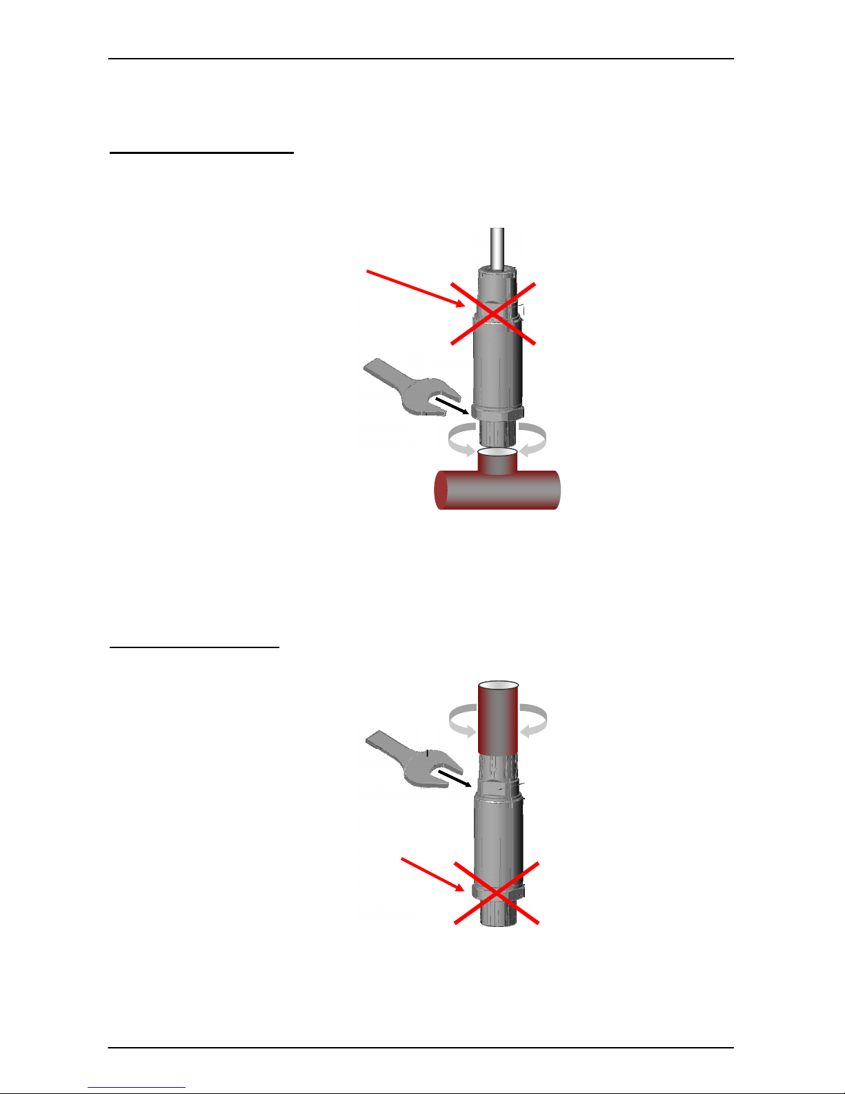
4. Wichtige Hinweise für die Conduit-Installation
Mechanische Installation
Elektrische Installation
Nicht zum Fixieren des
Sensors während der Conduit-
Installation verwenden!
Nicht zum Einschrauben in die
Hydraulikleitung verwenden!
Page 6

EDS 4000 mit ATEX-Zulassung Seite 6 von 26
Stand: 20.03.2018 HYDAC ELECTRONIC GMBH Mat. Nr.: 669736
5. Sicherheitshinweise
Wenn das Etikett nicht mehr lesbar ist, muss der Druckschalter außer Betrieb gesetzt
werden.
Die Dichtungen sind in regelmäßigen Abständen, in Abhängigkeit der klimatischen
Bedingungen und dem Medieneinfluss, auf ihre Funktionstüchtigkeit zu kontrollieren
und wenn erforderlich auszutauschen. Ersatzdichtungen sind als Ersatzteil bei
HYDAC ELECTRONIC erhältlich.
Es ist unbedingt auf die Verträglichkeit der Messmedien mit den verwendeten
Werkstoffen des Druckschalters zu achten; ebenso sind die Überlast- und Berstdrücke
einzuhalten (Angaben hierzu siehe "Technische Daten" und "Sicherheitstechnische
Daten" der EG Baumusterprüfbescheinigung).
Die interne Messmembrane des Druckschalters ist vor mechanischer Beschädigung zu
schützen. Dies gilt insbesondere bei gleichzeitigem Einsatz in Zone 0 und 1.
Bei Einsatz in Atmosphären von brennbaren Stäuben ist der Druckschalter
geschützt vor Beschädigungen und Schlag anzubringen.
Der Betrieb in Bereichen die Kategorie 1G Betriebsmittel erfordern, ist nur zulässig, wenn
anwendungs- und prozessbedingte intensive elektrostatische Aufladungsprozesse
ausgeschlossen sind.
Bei Betrieb in Bereichen, die das Geräteschutzniveau „Da“, „Db“, oder „Dc“ verlangen,
müssen externe Kabel- und Leitungsführungen so angeordnet sein, dass die Kabel und
Leitungen nicht der elektrostatischen Aufladung, durch einen Durchzug von Staub,
ausgesetzt sind.
Page 7
EDS 4000 mit ATEX-Zulassung Seite 7 von 26
Stand: 20.03.2018 HYDAC ELECTRONIC GMBH Mat. Nr.: 669736
Speziell für die programmierbare Ausführung des EDS 4000 gilt zusätzlich zu
beachten:
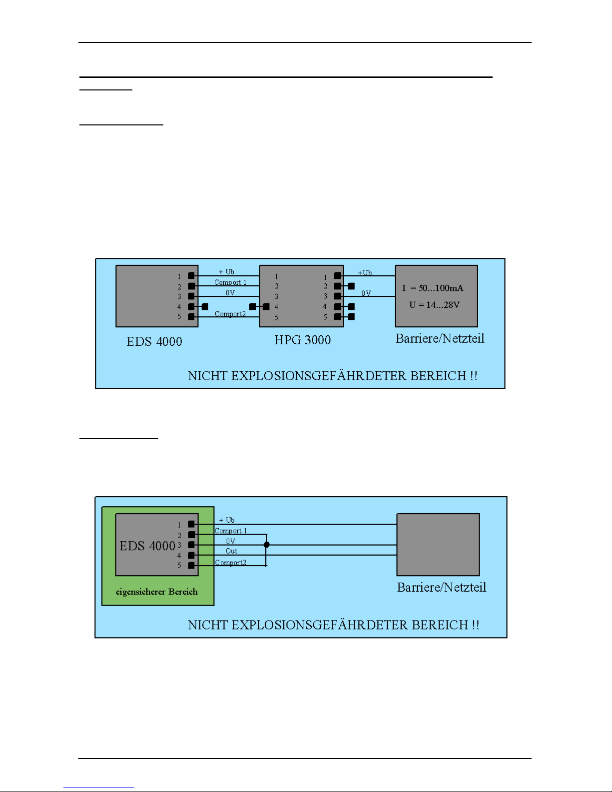
Programmierung
Diese Geräte dürfen nur außerhalb des explosionsgefährdeten Bereichs programmiert
werden. Die Programmierung darf nur mit dem von HYDAC ELECTRONIC angebotenen
Programmiergerät HPG 3000 oder ZBE-P1 vorgenommen werden. Die Versorgung des
Programmiergeräts muss mit einem Netzgerät oder Barriere, wie im EX-Bereich
vorgeschrieben, erfolgen. D.h. in das Programmiergerät dürfen maximal 28V und 100mA
eingespeist werden.
Eine minimale Versorgung von 14V und 50mA muss für den Betrieb des
Programmiergeräts zur Verfügung gestellt werden.
Inbetriebnahme
Bei Betrieb in explosionsgefährdeten Bereichen, sind die Programmierleitungen außerhalb
des explosionsgefährdeten Bereichs auf 0 V zu legen.
Page 8
EDS 4000 mit ATEX-Zulassung Seite 8 von 26
Stand: 20.03.2018 HYDAC ELECTRONIC GMBH Mat. Nr.: 669736
5.1 Bemerkungen zum Schaltausgang
Der Schaltausgang ist aus explosionstechnischen Gründen als Eingang definiert um die
Feldverdrahtung als einen Stromkreis zu betrachten. Dies erleichtert die Planung der
Feldverkabelung.
5.2 Sicherheitsbarrieren
Es sind duale Zener-Barrieren zu verwenden, bei denen der Signalzweig mit einer
Verpolungsdiode abgekoppelt ist. Der Signalzweig darf nur passiv belastet werden.
Folgende Sicherheitsbarrieren sind für die Serie “EDS 4000 Atex“ freigegeben:
Pepperl + Fuchs; www.pepperl-fuchs.com; Typ: Z 787
Telematic Ex STOCK; www.mtl.de; Modell Nr.: MTL 787
Andere, bauartgleiche Zener-Barrieren dürfen nur nach Rücksprache und mit
Zustimmung von HYDAC ELECTRONIC eingesetzt werden.
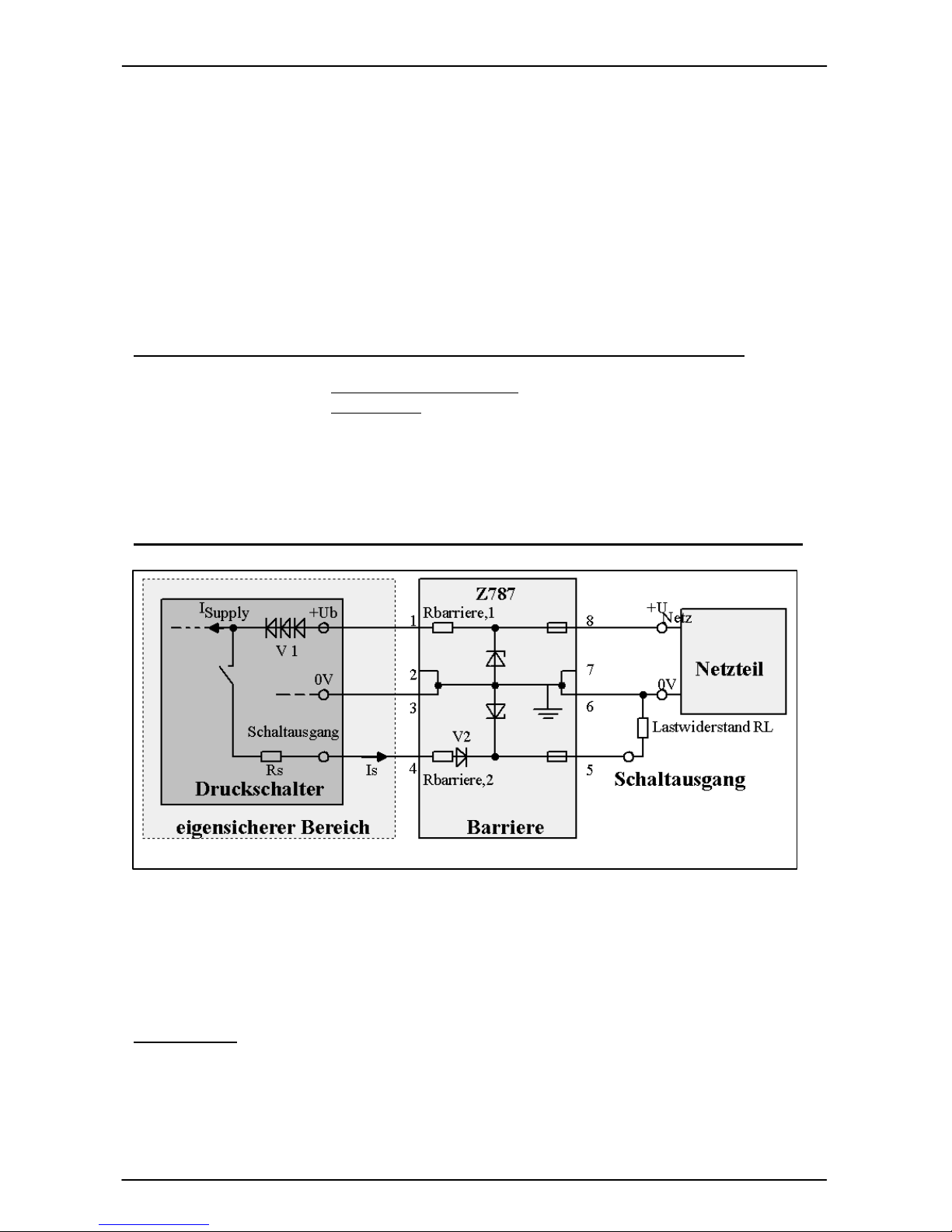
Beispiel für eine typ. Anordnung aus Netzteil, Zener-Barriere und Druckschalter:
Die vom Netzteil zur Verfügung gestellte Versorgungsspannung U
Netz
wird über die
Zener-Barriere zum Druckschalter geführt. In der Zener-Barriere befinden sich
Längswiderstände, Sicherungen und Zenerdioden als schützende Bauteile. Zudem
gewährleistet eine Diodenstrecke V1 im Druckschalter, dass keine Energie von außen
in den Schaltausgang fließen kann.
Anmerkung:
Der Betrieb des eigensicheren Druckschalters EDS 4000 im explosionsgefährdeten
Bereich erfordert bei der Auswahl der erforderlichen Zener-Barriere besondere Sorgfalt,
damit die Geräteeigenschaften in vollem Umfang genutzt werden können.
Page 9

EDS 4000 mit ATEX-Zulassung Seite 9 von 26
Stand: 20.03.2018 HYDAC ELECTRONIC GMBH Mat. Nr.: 669736
Suplly
barriere
bNetz
I
R
UU
I −
−
=
1,
min
max
max
2,
21
I
RRR
UUU
I
LbarriereS
VVb
S
≤
++
−−
=
2.
max
21
barriereS
VVb
L
RR
I
UUU
R −−
−
−
≥
2.
min
21*
barriereS
VVb
L
RR
I
UUU
R −−
−
−
≤
min
2,
21*
I
RRR
UUU
I
LbarriereS
VVb
S
≥
++
−−
=
1,min*
)(
barriereSupplyNetzb
RIIUU ⋅+−=
I
max
Max. Strom am
Schaltausgang
U
Netz
Ausgangsspannung am
Netzgerät
U
bmin
Min. Vers.-Spannung am
Druckschalter
R
barriere,1
Widerstand der Zener-
Barriere
im Versorgungskreis
I
Supply
Eigenverbrauch des
Druckschalters
U
V1
Spannung über die
Verpolungsdiode im
Druckschalter
UV2 Spannung über die Sperrdiode
in der Zener-Barriere
RS Innenwiderstand des
Druckschalters
R
barriere,2
Widerstand der Zener-Barriere
im Lastkreis
RL Lastwiderstand kundenseitig
I
max
Max. mögl. Strom am
Schaltausgang
U
b*
Für Anwendungsfall
erforderliche. Vers.-
Spannung
am Druckschalter
I
min
Min. erforderlicher Strom am
Schaltausgang
5.3 Vorbereitende Überlegungen für die Auslegung eines Systems:
Die Mindestversorgungsspannung U
b_min
= 14V des Druckschalters darf, auch bei
aktiviertem Schaltausgang, nicht unterschritten werden!
Es ist zu beachten, dass die Versorgungsspannung des Druckschalters aufgrund der
linearen Begrenzung der Zener-Barriere in Abhängigkeit des Strombedarfs des
Druckschalters und des Schaltausganges absinkt.
Zur Berechnung des maximal möglichen Schaltstroms ist der Spannungsabfall über der
Barriere und der Eigenstrom des Druckschalters zu berücksichtigen.
I
max
am Schaltausgang:
a) Der Lastwiderstand RL auf der Kundenseite muss nun so gewählt werden, dass der
aus dem Schaltausgang fließende Strom Is unterhalb I
max
bleibt. Dabei ist der
Spannungsabfall UV1 über die dreifach ausgelegte Verpolungsdiode V1, der
Spannungsabfall UV2 über der Barrierendiode V2, und der Spannungsabfall über dem
internen Widerstand R des Druckschalters sowie des Längswiderstands der Barriere
R
barriere,2
zu berücksichtigen:
Schaltstrom:
Bedingung für Lastwiderstand RL:
b) Ebenso muß bei der Auslegung des Lastwiderstands beachtet werden, dass der vom
Kunde geforderte minimale Laststrom I
min
erreicht werden kann.
Schaltstrom:
mit
Bedingung für Lastwiderstand RL:
Page 10

EDS 4000 mit ATEX-Zulassung Seite 10 von 26
Stand: 20.03.2018 HYDAC ELECTRONIC GMBH Mat. Nr.: 669736
Ω=Ω−Ω−
−
−
≥ 5,8236280
6,26
9,05,214
min
mA
VVV
R
L
VmAmAVUb 422,19327)410(24
*
=Ω⋅+−=
Ω=Ω−Ω−
−
−
≤ 2,128636280
10
9,05,2422,19
max
mA
VVV
R
L
mAmA
VV
I 6,264
327
1424
max
=−
Ω
−
≥
5.4 Berechnungsbeispiel:
Gegeben sind folgende Angaben:
Spezifische Daten der Nenndaten 28 V / 300 Ω
Zener-Barriere Z 787 R
barriere,1
= 327 Ω
R
barriere,2
= 36 Ω (+ 0,9V)
UV2 = 0,9 V
---------------------------------------------------------------------------------------------------------
Spezifische Daten des U
Netz
= 24V DC
Netzgerätes
---------------------------------------------------------------------------------------------------------
Spezifische Daten des Rs = 280 Ω
Druckschalters I
supply
= 4 mA
Ub
min
= 14 V
UV1 = 2,5 V
---------------------------------------------------------------------------------------------------------
Anforderung der Anwendung: I
s,min
= 10 mA
z.B.: digitaler SPS-Eingang mit 10mA Stromaufnahme
---------------------------------------------------------------------------------------------------------
Auslegung Lastwiderstand R
Lmin
:
Auslegung Lastwiderstand R
Lmax
:
Ergebnis:
Der Lastwiderstand muss zwischen
82,5 Ω
und
1286,2 Ω
liegen.
Page 11
EDS 4000 mit ATEX-Zulassung Seite 11 von 26
Stand: 20.03.2018 HYDAC ELECTRONIC GMBH Mat. Nr.: 669736
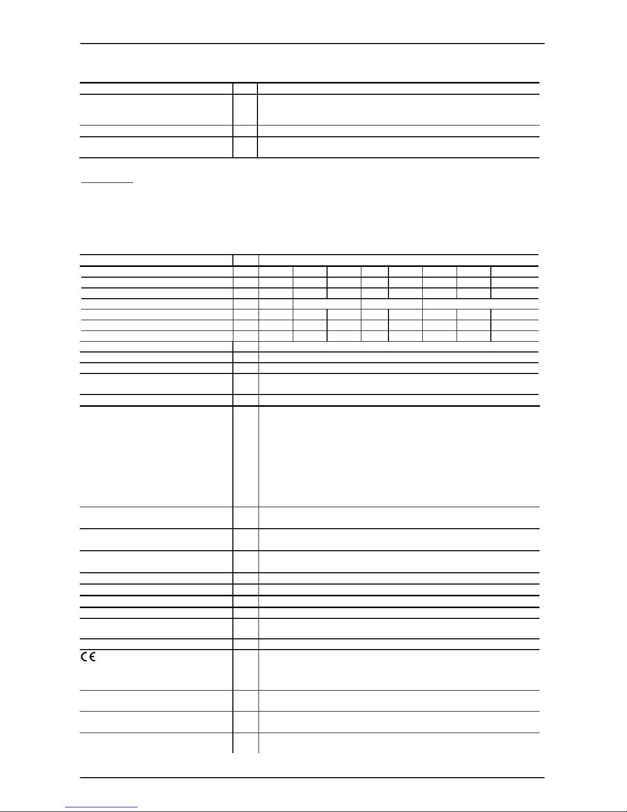
6. Technische Daten
6.1 EDS 41xx / 43xx
Eingangskenngrößen
EDS 4100 (Absolutdruck), EDS 4300 (Relativdruck)
absolut und relativ relativ
Messbereiche bar 1
2,5
4 6 10 16 25
40
Überlastbereiche bar 3
8
12 20 32 50 80
120
Berstdrücke bar 5
12
18 30 48 75 120
180
absolut und relativ relativ
Messbereiche psi 15
50
100 150 250 500
Überlastbereiche psi 45
150
290 450 725 1500
Berstdrücke psi 70
250
400 650 1000 2500
Mechanischer Anschluss siehe Typenschlüssel / Abmessungen
Anzugsdrehmoment, empfohlen siehe Abmessungen
Medienberührende Teile Sensor: Keramik
Anschlussstück: 1.4301
Dichtung: FPM / EPDM (siehe Typenschlüssel)
Ausgangsgrößen
Schaltausgang Transistorschaltausgang: PNP
Schaltstrom: im Betrieb I
max
≤ 34 mA
Schaltzyklen: > 100 Millionen
Schaltpunkt / Hysterese:
Je nach Version: fest eingestellt oder
frei programmierbar mit HYDAC HPG 3000/ ZBE P1
Anzugs- und Rückschaltverzögerung:
8 ms bis 2000 ms; (Standard 32 ms)
Je nach Version: fest eingestellt oder
frei programmierbar mit HYDAC HPG 3000/ ZBE P1
Genauigkeit nach DIN 16086,
Grenzpunkteinstellung
≤ ± 0,5 % FS typ.
≤ ± 1,0 % FS max.
Temperaturkompensation
Nullpunkt
≤ ± 0,02 % FS / °C typ.
≤ ± 0,03 % FS / °C max.
Temperaturkompensation
Spanne
≤ ± 0,02 % FS / °C typ.
≤ ± 0,03 % FS / °C max
Wiederholbarkeit
≤ ± 0,1 % FS bei 25 °C
Langzeitdrift
≤ ± 0,3 % FS / Jahr
Umgebungsbedingungen
Kompensierter Temperaturbereich -25 .. + 85 °C
Betriebs- /UmgebungsMediumstemperaturbereich
T6: Ta = -20 .. + 60 °C
T5,T4,T100: Ta = -25 .. + 70 °C
Lagertemperaturbereich -40 .. +100 °C
- Zeichen
EN 61000-6-1/ -2/ -3/ -4
EN 60079-0/-11/ 26
EN 61241-11
EN 50303
Vibrationsbeständigkeit nach
DIN EN 60068-2-6 bei 10 .. 500Hz
≤ 20 g
Schockfestigkeit nach
DIN EN 60068-2-27 (1 ms)
≤ 100 g
Schutzart nach DIN EN 60529
1)
Schutzart nach ISO 20653
IP 67 (Stecker M12x1, Stecker EN 175301-803)
IP 6K9K (1/2-14 NPT Conduit)
Relevante Daten
für die
Ex-Anwendung
I M1
II 1G, 1/2G, 2G
II 1 D
Versorgungsspannung 14 .. 28 V DC
Max. Eingangsstrom 100 mA 93 mA
Max. Eingangsleistung 0,7 W 0,65 W
Max. innere Kapazität 33 nF 33 nF
Max. innere Induktivität 0 mH 0 mH
Spannungsfestigkeit gegen Gehäuse
2)
50 VAC, mit integriertem Überspannungsschutz nach EN 61000-6-2
oder 500 VAC
Freigegebene Sicherheitsbarrieren Pepperl & Fuchs: Z 787
Telematic Ex STOCK: MTL 7087
Page 12
EDS 4000 mit ATEX-Zulassung Seite 12 von 26
Stand: 20.03.2018 HYDAC ELECTRONIC GMBH Mat. Nr.: 669736
Sonstige Größen
Verpolungsschutz der Versorgungsspannung, Lastkurzschlussfestigkeit,
Überspannungsschutz
vorhanden
Restwelligkeit Versorgungsspannung
≤ 5 %
Gewicht ca. 150 g (mit Stecker)
ca. 200g (mit ½-14NPT Conduit)
Anmerkung: FS (Full Scale) = bezogen auf den vollen Messbereich
1)
bei montierter Kupplungsdose entsprechender Schutzart
2)
siehe Typenschlüssel „Isolationsspannung“
6.2 EDS 44xx
Eingangskenngrößen
EDS 4400 (Relativdruck)
Messbereiche bar 60 100 250 400 600 1000 1600 2000
Überlastbereiche bar 120 200 500 800 1000 1600 2400 3000
Berstdrücke bar 300 500 1000 2000 2000 3000 3000 4000
Messbereiche psi 1000 3000 6000 9000 15000 20000 30000
Überlastbereiche psi 2900 7250 11600 14500 23200 38400 43500
Berstdrücke psi 7250 14500 29000 29000 43500 43500 58000
Mechanischer Anschluss siehe Typenschlüssel / Abmessungen
Anzugsdrehmoment siehe Abmessungen
Medienberührende Teile Edelstahl: 1.4542, 1.4548, 1.4301, 1.4435, 1.4571, 1.4404
Dichtung: FPM
Ausgangsgrößen
Schaltausgang
1)
1)
Transistorschaltausgang: PNP
Schaltstrom: im Betrieb I
max
≤ 34 mA
Schaltzyklen: > 100 Millionen
Schaltpunkt / Hysterese:
Je nach Version: fest eingestellt oder
frei programmierbar mit HYDAC HPG 3000/ ZBE P1
Anzugs- und Rückschaltverzögerung:
8 ms bis 2000 ms; (Standard 32 ms)
Je nach Version: fest eingestellt oder
frei programmierbar mit HYDAC HPG 3000/ ZBE P1
Genauigkeit nach DIN 16086,
Grenzpunkteinstellung
≤ ± 0,5 % FS typ.
≤ ± 1,0 % FS max.
Temperaturkompensation
Nullpunkt
≤ ± 0,02 % FS / °C typ.
≤ ± 0,03 % FS / °C max.
Temperaturkompensation
Spanne
≤ ± 0,02 % FS / °C typ.
≤ ± 0,03 % FS / °C max
Wiederholbarkeit
≤ ± 0,1 % FS bei 25 °C
Langzeitdrift
≤ ± 0,3 % FS / Jahr
Umgebungsbedingungen
Kompensierter Temperaturbereich -25 .. + 85 °C
Betriebs- /UmgebungsMediumstemperaturbereich
T6: Ta = -20 .. + 60 °C
T5,T4,T100: Ta = -25 .. + 70 °C
Lagertemperaturbereich -40 .. +100 °C
- Zeichen
EN 61000-6-1/ -2/ -3/ -4
EN 60079-0/-11/ 26
EN 61241-11
EN 50303
Vibrationsbeständigkeit nach
DIN EN 60068-2-6 bei 10 .. 500Hz
≤ 20 g
Schockfestigkeit nach
DIN EN 60068-2-27 (1 ms)
≤ 100 g
Schutzart nach DIN EN 60529
2)
Schutzart nach ISO 20653
IP 67 (Stecker M12x1, Stecker EN 175301-803)
IP 6K9K (1/2-14 NPT Conduit)
Page 13
EDS 4000 mit ATEX-Zulassung Seite 13 von 26
Stand: 20.03.2018 HYDAC ELECTRONIC GMBH Mat. Nr.: 669736
Relevante Daten für die
Ex-Anwendung
I M1
II 1G, 1/2G, 2G
II 1 D
Versorgungsspannung 14 .. 28 V DC
Max. Eingangsstrom 100 mA 93 mA
Max. Eingangsleistung 0,7 W 0,65 W
Max. innere Kapazität 33 nF 33 nF
Max. innere Induktivität 0 mH 0 mH
Spannungsfestigkeit gegen Gehäuse
3)
50 VAC, mit integriertem Überspannungsschutz nach EN 61000-6-2
oder 500 VAC
Freigegebene Sicherheitsbarrieren Pepperl & Fuchs: Z 787
Telematic Ex STOCK: MTL 7087
Sonstige Größen
Verpolungsschutz der Versorgungsspannung, Lastkurzschlussfestigkeit,
Überspannungsschutz
vorhanden
Restwelligkeit Versorgungsspannung
≤ 5 %
Gewicht ca. 150 g (mit Stecker)
ca. 200g (mit ½-14NPT Conduit)
Anmerkung: FS (Full Scale) = bezogen auf den vollen Messbereich
1)
Bei Messbereich > 9000psi muss die Schaltpunktprogrammierung mittels Programmiergerät ZBE-P1
erfolgen
2)
bei montierter Kupplungsdose entsprechender Schutzart
3)
siehe Typenschlüssel „Isolationsspannung“
Page 14

EDS 4000 mit ATEX-Zulassung Seite 14 von 26
Stand: 20.03.2018 HYDAC ELECTRONIC GMBH Mat. Nr.: 669736
7
. Typenschlüssel zur Identifizierung des gelieferten Gerätes
EDS 4 x x x – xxxx - x- A x x – xxx – x 1 (xxxx / xxxx bar) xx cm
Genauigkeit
1 = Keramik / Absolutdruck
3 = Keramik / Relativdruck
4 = Dünnfilm / Relativdruck
Mechanischer Anschluss
1 = G1/2 DIN EN 837
4 = G 1/4 A ISO 1179-2, Außengewinde
5 = 7/16-20 UNF 2B (SAE 4), Innengewinde
6 = 7/16-20 UNF 2A (SAE 4), Außengewinde
7 = 9/16-18 UNF 2A (SAE 6), Außengewinde
8 = 1/4-18 NPT, (Außengewinde)
B = F250C Autoclave (9/16-18UNF2B),
Innengewinde
C = 7/16-20 UNF 2B (SF-250-CX, Autoclave)
F = 1/4-18 NPT, Innengewinde
Elektrischer Anschluss
5 = Gerätestecker, EN 175301-803, 3 pol. + PE
6 = Gerätestecker, M12x1, 4 pol.
8 = Gerätestecker, M12x1, 5 pol.
A = Gerätestecker, EN 175301-803, 3 pol. +PE,
1/2“ Conduit Innengewinde
G = 1/2-14 NPT Conduit (Außengewinde),freies Kabelende
Messbereich
Angabe in bar oder psi
Schaltausgang
0 = Schließer
1 = Öffner
P = programmierbar
Zulassung
A = ATEX (genaue Angaben siehe Zertifikat)
Isolationsspannung
H = 500 V AC gegen Gehäuse
N = 50 V AC gegen Gehäuse
Schutzklassen und Einsatzgebiete (siehe Tabelle, Kap. 7.1)
1 = I M1 Ex ia I Ma
2 = II 1G Ex ia IIC T4, T5, T6 Ga
3 = II 2G Ex ia IIC T4, T5, T6 Gb/ II 1/2 G Ex ia IIC T4, T5, T6 Ga/Gb
8 = II 1D Ex ia IIIC T100°C Da
Modifikationsnummer
000 = Standard
Dichtungsmaterial (nur bei HDA 41xx / 43xx)
F = FPM-Dichtung (z.B für Hydrauliköle)
E = EPDM-Dichtung (z.B. für Kältemittel)
Anschlussmaterial (nur bei HDA 41xx / 43xx)
1 = Edelstahl
Schaltpunkt (entfällt bei programmierbarer Version)
Rückschaltpunkt (entfällt bei programmierbarer Version)
Einheit der Schaltpunkte
Kabellänge (nur für elektr. Anschluss „G“)
Angabe in cm oder inch im Klartext
Page 15

EDS 4000 mit ATEX-Zulassung Seite 15 von 26
Stand: 20.03.2018 HYDAC ELECTRONIC GMBH Mat. Nr.: 669736
7.1 Auswertetabelle (Protection concept): Zuordnung der Schutzklassen und
Einsatzbereiche
Protection concept (Schutzklassen und Einsatzbereiche)
Typenschlüssel-
Kennzahl
1 2 3 8
Schutzklasse
I M1 Ex ia I Ma
II 1G Ex ia IIC
T4, T5, T6 Ga
II 2G Ex ia IIC
T4,T5,T6 Gb
II 1/2G Ex ia IIC
T4,T5,T6 Ga/Gb
II 1D Ex ia IIIC
T100°C Da
Einsatzgebiete
Gruppe I
Kategorie M1
Bergbau
Schutzart:
Eigensicher (ia)
mit Barriere
Gruppe II
Kategorie 1G
Gase
Schutzart:
Eigensicher (ia)
mit Barriere
Einsatz in:
Zone 0,1,2
Gruppe II
Kategorie 2G, 1/2G
Gase
Schutzart:
Eigensicher (ia)
mit Barriere
Einsatz in:
Zone 1
Zone 2
Anbau an:
Zone 0
Gruppe II
Kategorie 1D
Stäube
Schutzart:
Eigensicher (ia)
mit Barriere
Einsatz in:
Zone 20
Zone 21
Zone 22
Anbau an:
Zone 20
Elektrischer
Anschluss
(siehe Typenschlüssel)
5, 6, 8, A, G 5, 6, 8, G 5, 6, 8, A, G 5, 6, 8, G
Page 16
EDS 4000 mit ATEX-Zulassung Seite 16 von 26
Stand: 20.03.2018 HYDAC ELECTRONIC GMBH Mat. Nr.: 669736
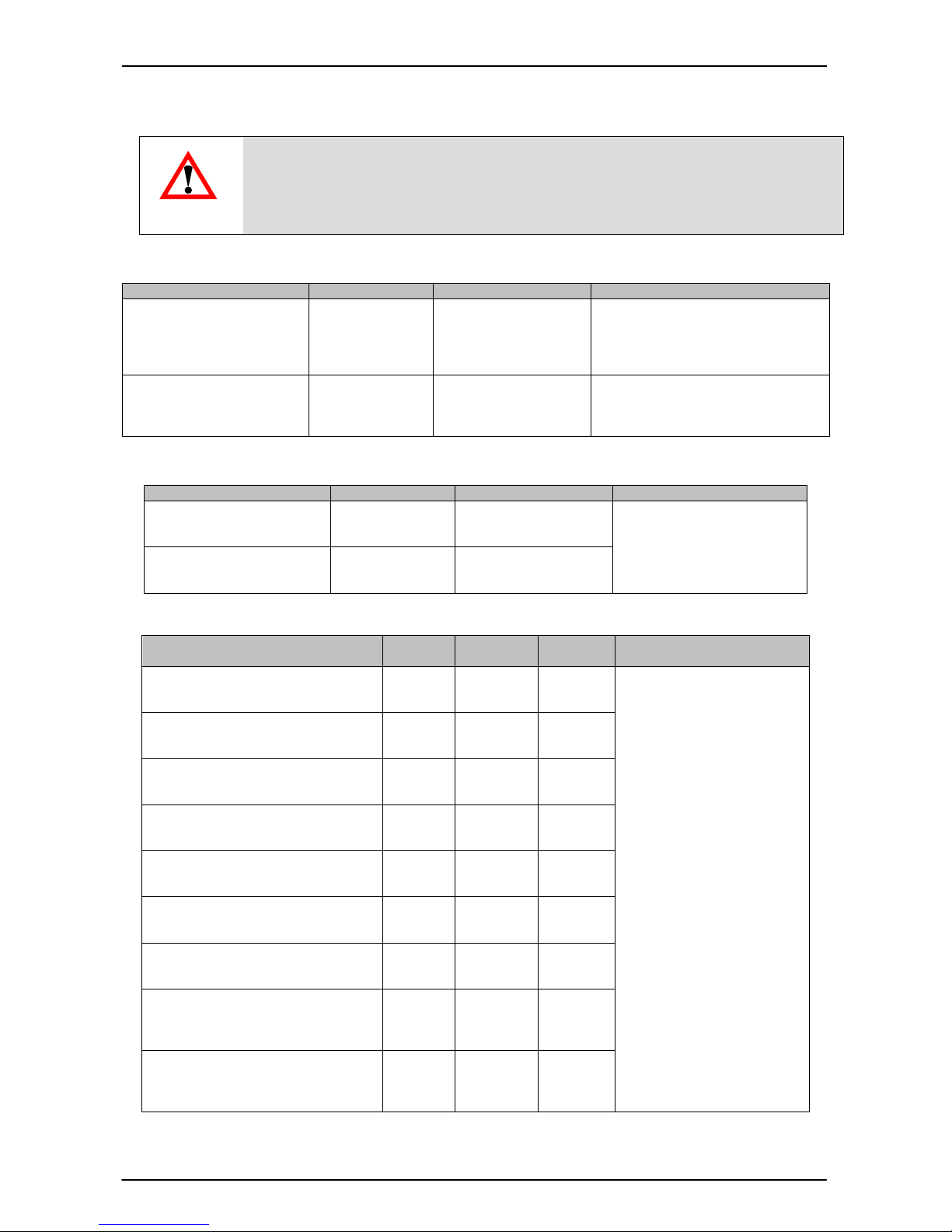
7.2 Zubehör für den elektrischen Anschluss
Nur die nachfolgend aufgeführten Anschlussstecker und -leitungen sind
in der Zulassung inbegriffen und dürfen für die entsprechenden
Einsatzbereiche verwendet werden.
ACHTUNG !
Konfektionierbare Stecker (im Lieferumfang der Anschlussvariante enthalten)
Steckertyp
Material
-
Nr. Anschluss
-
Variante
Einsatzbereich
Gerätestecker
DIN 43650 (3-pol. + PE)
5 I M1 Ex ia I Ma
II 1G Ex ia IIC T4,T5,T6 Ga
II 2G Ex ia IIC T4,T5,T6 Gb
II 1/2G Ex ia IIC T4,T5,T6 Ga/Gb
II 1D Ex ia IIIC T100°C Da
Gerätestecker
DIN 43650 (3-pol. + PE)
1/2“ Conduit Innengewinde
A I M1 Ex ia I Ma
II 2G Ex ia IIC T4,T5,T6 Gb
II 1/2G Ex ia IIC T4,T5,T6 Ga/Gb
Konfektionierbare Stecker (nicht im Lieferumfang der Anschlussvariante enthalten)
Steckertyp
Material
-
Nr. Anschluss
-
Variante
Einsatzbereich
ZBE 06
Kupplungsdose M12x1
4-pol., abgewinkelt
6006788 6
II 1D Ex ia IIIC T100°C Da
ZBE 08
Kupplungsdose M12x1
5-pol., abgewinkelt
6006786 8
Anschlussleitungen M12x1 (nicht im Lieferumfang der Anschlussvariante enthalten)
Typ Material
-
Nr.
Anschluss
-
Variante
Schirm
Einsatzbereich
ZBE 06-02
Kupplungsdose M12x1 mit 2m Leitung
4-pol., abgewinkelt
6006790 6 nein
I M1 Ex ia I Ma
II 1G Ex ia IIC T4,T5,T6 Ga
II 2G Ex ia IIC T4,T5,T6 Gb
II 1/2G Ex ia IIC T4,T5,T6 Ga/Gb
II 1D Ex ia IIIC T100°C Da
ZBE 06-05
Kupplungsdose M12x1 mit 5m Leitung
4-pol., abgewinkelt
6006789 6 nein
ZBE 06S-05
Kupplungsdose M12x1 mit 5m Leitung
4-pol., abgewinkelt
6044891 6 ja
ZBE 08-02
Kupplungsdose M12x1 mit 2m Leitung
5-pol., abgewinkelt
6006792 6 + 8 nein
ZBE 08-05
Kupplungsdose M12x1 mit 5m Leitung
5-pol., abgewinkelt
6006791 6 + 8 nein
ZBE 08S-02
Kupplungsdose M12x1 mit 2m Leitung
5-pol., abgewinkelt
6019455 6 + 8 ja
ZBE 08S-05
Kupplungsdose M12x1 mit 5m Leitung
5-pol., abgewinkelt
6019456 6 + 8 ja
ZBE 08S-10
Kupplungsdose M12x1 mit 10m
Leitung
5-pol., abgewinkelt
6023102 6 + 8 ja
ZBE 08S-30
Kupplungsdose M12x1 mit 30m
Leitung
5-pol., abgewinkelt
6035063 6 + 8 ja
Alle oben aufgeführten Anschlussleitungen besitzen eine Leitungs-Kapazität von < 200 nF
/ km sowie eine Leitungs-Induktivität von < 1 mH / km.
Page 17

EDS 4000 mit ATEX-Zulassung Seite 17 von 26
Stand: 20.03.2018 HYDAC ELECTRONIC GMBH Mat. Nr.: 669736
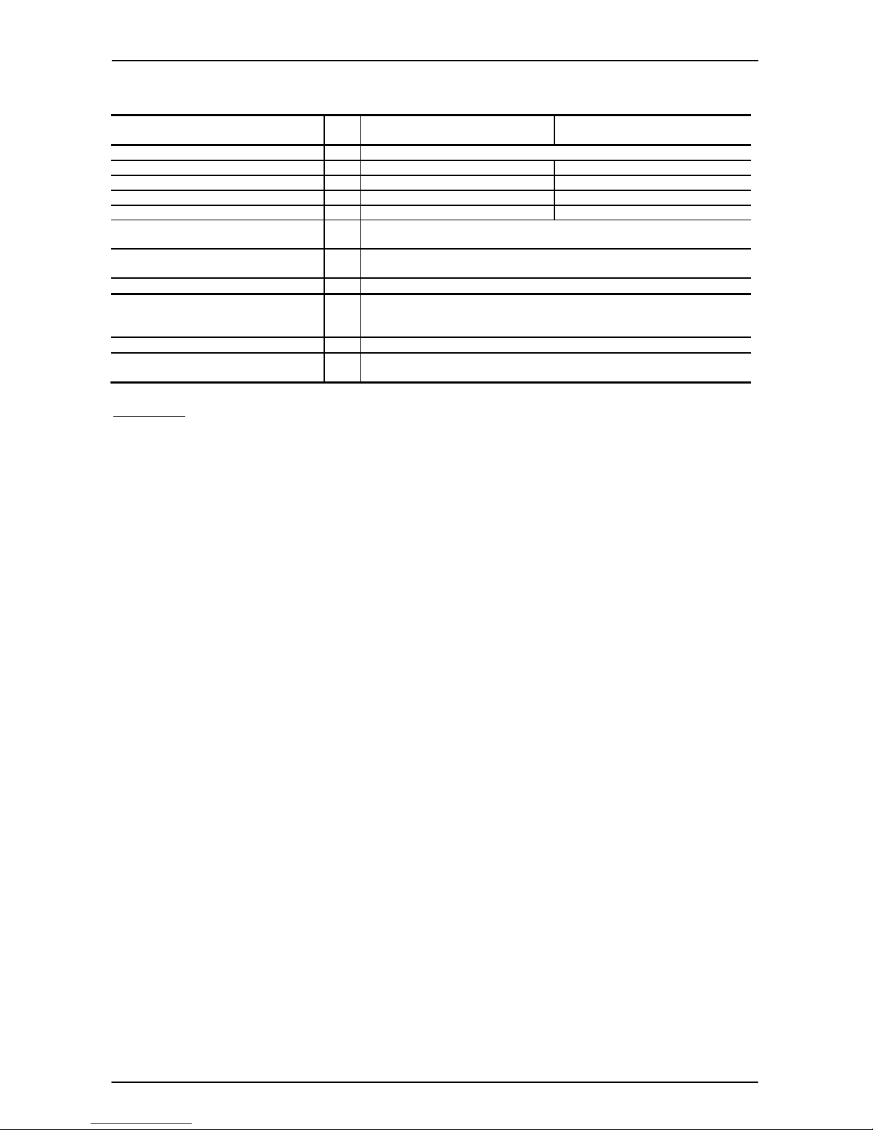
8. Seriennummer
In der Seriennummer ist neben der fortlaufenden Seriennummer die Kalenderwoche
und das Jahr der Herstellung des Gerätes enthalten.
Aufbau Seriennummer:
XX Fertigungsjahr z.B. : 07 2017
yy Kalenderwoche z.B. : 33
k Seriennummer-Index z.B. : -, A, B
zzzzzz fortlaufende Seriennummer z.B. : 000001
xxyykzzzzzz
733A000001
Page 18

EDS 4000 mit ATEX-Zulassung Seite 18 von 26
Stand: 20.03.2018 HYDAC ELECTRONIC GMBH Mat. Nr.: 669736
9. Einstellbereiche (nur für programmierbare Ausführung)
Mit dem Programmiergerät HPG 3000 oder ZBE-P1 können folgende Einstellungen
vorgenommen werden:
Messbereich
in bar
Schaltpunkt
↵↵↵↵ in bar
Hys
terese
in bar
Schrittweite
↵↵↵↵ in bar
Voreinstellung
Schaltpunkt
Voreinstellung
Hysterese
1; 2,5; 4; 6
5 % .. 100 %
des
Mess-
bereichs
1 % .. 96 %
des
Mess-
bereichs
0,01
50 %
des
Mess-
bereichs
25 %
des
Mess-
bereichs
10; 16 0,05
25; 40 0,1
60; 100 0,2
250 0,5
400; 600 1
1000 2
1600 5
2000 5
Messbereich
in psi
Schaltpunkt
in psi
Hysterese
in psi
Schrittweite
in psi
Voreinstellung
Schaltpunkt
Voreinstellung
Hysterese
15; 30; 50
5 % .. 100 %
des
Mess-
bereichs
1 % .. 96 %
des
Mess-
bereichs
0,1
50 %
des
Mess-
bereichs
25 %
des
Mess-
bereichs
100; 150; 250 0,5
500 1
1000 2
3000 5
6000 10
9000 20
150001) 50
200001) 50
300001) 50
Min. Dauer
in ms
Max. Dauer
in ms
Schrittweite
in ms
Voreinstellung
Verzögerung
in ms
Einschaltverzögerung
Ton1 / Ton2
8 2040 8 32
Ausschaltverzögerung
ToF1 / ToF2
8 2040 8 32
1)
Bei Messbereich > 9000psi muss die Schaltpunktprogrammierung mittels Programmiergerät ZBE-P1
erfolgen
Page 19

EDS 4000 mit ATEX-Zulassung Seite 19 von 26
Stand: 20.03.2018 HYDAC ELECTRONIC GMBH Mat. Nr.: 669736
10. Geräteabmessungen
10.1 Mechanische Anschlussvarianten
7/16-20 UNF 2B (SAE 4), 7/16-20 UNF 2A (SAE 4),
Innengewinde Außengewinde
Anzugsdrehmoment: 15 Nm Anzugsdrehmoment: 15 Nm
9/16-18 UNF 2A (SAE 6), 7/16-20 UNF 2B
Außengewinde (SF-250-CX, Autoclave), Innengewinde
Anzugsdrehmoment: 20 Nm Anzugsdrehmoment: 15 Nm
1/4-18 NPT, 1/4-18 NPT,
Außengewinde Innengewinde
Anzugsdrehmoment: maximal 40 Nm Anzugsdrehmoment: maximal 40 Nm
G1/4A ISO 1179-2,
Außengewinde
Anzugsdrehmoment: 20 Nm
Gerätestecker
EN 175301-803
3 pol. + PE
Page 20

EDS 4000 mit ATEX-Zulassung Seite 20 von 26
Stand: 20.03.2018 HYDAC ELECTRONIC GMBH Mat. Nr.: 669736
G1/2 DIN EN 837 F250C Autoclave (9/16-18 UNF2B), Innengewinde
Anzugsdrehmoment: maximal 45Nm Anzugsdrehmoment: maximal 40 Nm
10.2 Elektrische Anschlussvarianten:
1/2-14 NPT Conduit (Außengewinde)
Gerätestecker, M 12 x 1, 4 oder 5 pol.
Gerätestecker EN 175301-803 , 3 pol. + PE,
1/2" Conduit Innengewinde
Page 21

EDS 4000 mit ATEX-Zulassung Seite 21 von 26
Stand: 20.03.2018 HYDAC ELECTRONIC GMBH Mat. Nr.: 669736
11. Zertifikat
Page 22

EDS 4000 mit ATEX-Zulassung Seite 22 von 26
Stand: 20.03.2018 HYDAC ELECTRONIC GMBH Mat. Nr.: 669736
Page 23

EDS 4000 mit ATEX-Zulassung Seite 23 von 26
Stand: 20.03.2018 HYDAC ELECTRONIC GMBH Mat. Nr.: 669736
Page 24

EDS 4000 mit ATEX-Zulassung Seite 24 von 26
Stand: 20.03.2018 HYDAC ELECTRONIC GMBH Mat. Nr.: 669736
Page 25

EDS 4000 mit ATEX-Zulassung Seite 25 von 26
Stand: 20.03.2018 HYDAC ELECTRONIC GMBH Mat. Nr.: 669736
12. Konformitätserklärung
Page 26

EDS 4000 mit ATEX-Zulassung Seite 26 von 26
Stand: 20.03.2018 HYDAC ELECTRONIC GMBH Mat. Nr.: 669736
HYDAC ELECTRONIC GMBH
Hauptstraße 27
D-66128 Saarbrücken
Germany
Web: www.hydac.com
E-Mail: electronic@hydac.com
Tel.: +49-(0)6897-509-01
Fax: +49-(0)6897-509-1726
HYDAC Service
Für Fragen zu Reparaturen steht
Ihnen der HYDAC Service zur
Verfügung:
HYDAC SERVICE GMBH
Hauptstr. 27
D-66128 Saarbrücken
Germany
Tel.: +49-(0)6897-509-1936
Fax: +49-(0)6897-509-1933
Anmerkung
Die Angaben in diesem Handbuch beziehen sich auf die beschriebenen Betriebsbedingungen
und Einsatzfälle. Bei abweichenden Einsatzfällen und/oder Betriebsbedingungen wenden Sie
sich bitte an die entsprechende Fachabteilung.
Bei technischen Fragen, Hinweisen oder Störungen nehmen Sie bitte Kontakt mit Ihrer
HYDAC- Vertretung auf.
Technische Änderungen sind vorbehalten.
Page 27

Status: 2018-03-20 HYDAC ELECTRONIC GMBH Mat. No.: 669736
Operating Instructions
Pressure Switch Series EDS 4000
for Intrinsically Safe
ATEX- approval
( Translation of original manual )
Protection ratings and applications:
I M1 Ex ia I Ma
II 1G Ex ia IIC T4, T5, T6 Ga
II 1/2 G Ex ia IIC T4, T5, T6 Ga/Gb
II 2 G Ex ia IIC T4, T5, T6 Gb
II 1 D Ex ia IIIC T100°C Da
Certificate no.: BVS 07 ATEX E 041 X
X (for special notes)
Inspection unit: DEKRA EXAM GmbH
Identification number of CE-Inspection unit EXAM: 0158
Page 28

EDS 4000 for Intrinsically Safe Circuits Page 2 of 26
Status: 2018-03-20 HYDAC ELECTRONIC GMBH Mat. No.: 669736
Page 29

EDS 4000 for Intrinsically Safe Circuits Page 3 of 26
Status: 2018-03-20 HYDAC ELECTRONIC GMBH Mat. No.: 669736
Table of content
1. General Remarks ........................................................................................................... 4
2. Function .......................................................................................................................... 4
3. Installation and Commissioning Information .............................................................. 4
4. Important mounting instructions for Conduit connection ......................................... 5
5. Safety instructions ......................................................................................................... 6
5.1 Notes on switching output .......................................................................................... 8
5.2 Safety barriers ........................................................................................................... 8
5.3 Preliminary considerations for designing a system: ................................................... 9
5.4 Calculation example: ............................................................................................... 10
6. Technical Data ............................................................................................................. 11
6.1 EDS 41xx / 43xx ...................................................................................................... 11
6.2 EDS 44xx ................................................................................................................. 12
7. Model code to identify the delivered part .................................................................. 14
7.1 Evaluation table (Protection concept): Assignment of the protection types and
application areas ........................................................................................................... 15
7.2 Accessories for the electrical connection ................................................................. 16
8. Serial Number .............................................................................................................. 17
9. Settings ranges (only for programmable version) .................................................... 18
10. Dimensions ................................................................................................................ 19
10.1 Mechanical Connection: ........................................................................................ 19
10.2 Electrical connection: ............................................................................................. 20
11. Certificat ..................................................................................................................... 21
12. Declaration of conformity ......................................................................................... 25
Page 30

EDS 4000 for Intrinsically Safe Circuits Page 4 of 26
Status: 2018-03-20 HYDAC ELECTRONIC GMBH Mat. No.: 669736
1. General Remarks
If you have any questions regarding the technical specifications or the suitability for your
applications, please contact our Technical Sales Department. The series EDS 4000
pressure switches are individually tested and factory-calibrated at a computer operated
test station. They are maintenance-free and operate perfectly when used according to
the data (see Technical Specifications). If faults do nonetheless occur, please contact
HYDAC Service. Interference by anyone other than HYDAC personnel will invalidate all
warranty claims as well as the ATEX approval.
2. Function
The pressure signal measured by the sensor is converted internally into a signal which is
proportional to the pressure.
At a fixed or programmable switch point, the switching output will react.
The power supply is connected via a plug connector or a permanently attached cable.
3. Installation and Commissioning Information
The pressure switches can be mounted directly to the hydraulic system via the threaded
connection. In order to prevent mechanical damage in the case of critical applications
involving heavy vibrations or knocks, we recommend securing the unit with an elastomer
clamp and decoupling the hydraulic port via a Minimess hose.
Tightening torque see dimensions.
Pressure switches with a rated pressure of < 100 bar provide for pressure equalization
with the ambient pressure.
This is enabled by a small hole underneath the plug connector. The connector is covered
on the inside by a special membrane which prevents moisture from seeping into the unit
from the outside. In order to prevent the hole from becoming clogged, in moist or dusty
environments the pressure switch should be mounted in a horizontal position, or vertically
with the pressure port pointing downwards.
Connection must be carried out by a properly qualified specialist in accordance with the
regulations relating to potentially explosive areas (e.g. EN 60079-14).
The series 4000 pressure switches carry the mark in accordance with directive
2014/34 EU (ATEX).
The Certificate of Conformity is enclosed. The requirements of the standards (see
technical specifications) are fulfilled only if the pressure switch housing is grounded
correctly by a qualified person. Potential equalization is required along the intrinsically
safe electrical circuit in the N type model (insulation voltage
≤ 50 VAC). If the pressure switch is connected using hoses, the housing must be
grounded separately.
On the EDS 4000 series, type H (insulation voltage ≤ 500 VAC), the cable length to the
pressure switch must be max. 30 m (overvoltage protection to DIN EN 61000-6-2). If the
cable length exceeds 30 m, overvoltage protection must be provided by the customer.
On units with a measuring range ≤ 100 bar the operator must make sure that on cables
with venting hose, venting only occurs in the Non-Ex area.
The fitting of sensors with a conduit connection may only be carried out utilising the
tightening nut on the mechanical connection and not using the flats on the cable outlet.
Page 31

EDS 4000 for Intrinsically Safe Circuits Page 5 of 26
Status: 2018-03-20 HYDAC ELECTRONIC GMBH Mat. No.: 669736
4. Important mounting instructions for Conduit connection
Mechanical installation
Electrical installation
Do not use for screwing into the
mechanical connection!
Do not use for fixing the
sensor during electrical
conduit installation!
Page 32

EDS 4000 for Intrinsically Safe Circuits Page 6 of 26
Status: 2018-03-20 HYDAC ELECTRONIC GMBH Mat. No.: 669736
5. Safety instructions
The pressure switch may no longer be used when the label becomes illegible.
The seals and gaskets must be checked at regular intervals to check that they function
properly in keeping with the climatic conditions and the influence of the media, and must
be changed as required. Replacement seals and gaskets can be obtained from HYDAC
ELECTRONIC GMBH.
It is imperative that the measurement fluid is compatible with the materials used in the
pressure switch; similarly, the overload pressures and burst pressures must be strictly
adhered to (see the “Technical Specifications” and “Safety Information” of the EC type
examination certificate).
The internal measurement membrane of the pressure switch must be protected against
mechanical damage. This applies especially if the unit is used simultaneously in zones 0
and 1.
When used in atmospheres containing combustible dusts, the pressure switch must be
installed in such a way that it is protected from damage and knocks.
Operation in areas requiring category 1G equipment is only permitted if operational and
process-related intensive electrostatic charges are eliminated.
When operated in locations requiring an equipment protection level „Da“, „Db“, or „Dc“,
electrostatic charge due to draft of dust-laden air at external cables and leads must be
prevented. The installation of the external cables and leads must be carried out
accordingly.
Page 33

EDS 4000 for Intrinsically Safe Circuits Page 7 of 26
Status: 2018-03-20 HYDAC ELECTRONIC GMBH Mat. No.: 669736
Barrier/Power supply
Non
-
potentially explosive area !!
EDS 4000 HPG 3000
Non
-
potentially explosive area !!
Barrier/Power supply
Intrinsically safe area
The following instructions apply specifically and additionally to the programmable
version of the EDS 4000:
Programming
These devices may only be programmed outside the potentially explosive location.
Programming may only be carried out using the HPG 3000 or ZBE-P1 programming unit
available from HYDAC ELECTRONIC. The electrical supply to the programming unit must
be via a power supply or barrier, as stipulated for the EX location; i.e. the programming
unit may only be supplied with maximum 28V and 100mA.
A minimum supply of 14V and 50mA must be made available to operate the programming
unit.
Commissioning
Before operating in potentially explosive areas, remove the programming cables from the
potentially explosive area or set at 0V.
Page 34

EDS 4000 for Intrinsically Safe Circuits Page 8 of 26
Status: 2018-03-20 HYDAC ELECTRONIC GMBH Mat. No.: 669736
5.1 Notes on switching output
For technical reasons relating to explosions the switching output is defined as an input
in order to treat the field wiring as an electric circuit. This facilitates the design of the
field cabling.
5.2 Safety barriers
Dual Zener barriers must be used in which the signal branch is disconnected using a
reverse polarity diode. The signal branch may only take a passive load.
The following safety barriers are approved for the “EDS 4000 Atex“ series:
Pepperl + Fuchs; www.pepperl-fuchs.com; Type: Z 787
Telematic Ex STOCK; www.mtl.de; Model No.: MTL 787
Other Zener barriers of similar design may only be used after consulting and obtaining
the agreement of HYDAC ELECTRONIC.
Example of a typical configuration of power supply, Zener barrier and pressure
switch:
The supply voltage U
Netz
provided by the mains supply is carried via the Zener barrier to
the pressure switch. In the Zener barrier the protective components are series
resistance, fuses and Zener diodes. In addition a diode region V1 in the pressure switch
ensures that no energy can flow from the outside into the switch output.
Note:
Operating the intrinsically safe pressure switch EDS 4000 in a potentially explosive
location demands particular care when selecting the required Zener barrier in order that
the device characteristics can be used to the full extent.
Pressure switch
Barrier
Intrinsically safe area
Switching output
Load resistance R
L
Power
supply
+
U
S
upply
Switching output
Page 35

EDS 4000 for Intrinsically Safe Circuits Page 9 of 26
Status: 2018-03-20 HYDAC ELECTRONIC GMBH Mat. No.: 669736
Supply
barrier
bSupply
I
R
UU
I −
−
=
1,
min
max
max
2,
21
I
RRR
UUU
I
LbarrierS
VVb
S
≤
++
−
−
=
2.
max
21
barrierS
VVb
L
RR
I
UUU
R −−
−−
≥
2.
min
21*
barrierS
VVb
L
RR
I
UUU
R −−
−−
≤
min
2,
21*
I
RRR
UUU
I
LbarrierS
VVb
S
≥
++
−
−
=
1,min*
)(
barrierSupplySupplyb
RIIUU ⋅+−=
I
max
Max. current at switch output
U
Supply
Output voltage at power
supply unit
U
bmin
Min. Supply voltage at the
pressure switch
R
barrier ,1
Resistance of the Zener
barrier in the supply circuit
I
Supply
Power consumption of the
pressure switch
U
V1
voltage via the reverse polarity
diode in the pressure switch
UV2 Voltage via the blocking diode in
the Zener barrier
RS Internal resistance of the
pressure switch
R
barrier,2
Resistance of the Zener barrier
in the load circuit
RL
Load resistance on the customer
side
I
max
Max. poss. current at the
switching output
U
b*
Supply voltage required for
application at pressure switch
I
min
Min. Current required at
switch output
5.3 Preliminary considerations for designing a system:
The voltage must not fall below the minimum supply voltage U
b_min
= 14V of the
pressure switch, also on an activated switching output!
Please note that the supply voltage of the pressure switch can drop due to the linear
limit of the Zener barrier subject to the power requirement of the pressure switch and
the switch output.
To calculate the maximum possible switching current, the voltage drop via the barrier
and the intrinsic current of the pressure switch must be taken into consideration.
I
max
at switch output:
a) The load resistance RL on the customer side must now be selected in such a way
that the current Is flowing out of the switch output remains below I
max
. At the same time
the voltage drop UV1 across the threefold reverse polarity diode V1, the voltage drop UV2
across the barrier diode V2, the voltage drop via the internal resistance R of the
pressure switch and the series resistance of the barrier R
barrier,2
must be taken into
account:
Switching current:
Condition for load resistance RL:
b) Equally, when designing the load resistance, ensure that the minimum load current
I
min
required by the customer can be achieved.
Switching current:
with
condition for load resistance RL:
Page 36

EDS 4000 for Intrinsically Safe Circuits Page 10 of 26
Status: 2018-03-20 HYDAC ELECTRONIC GMBH Mat. No.: 669736
Ω=Ω−Ω−
−
−
≥ 5.8236280
6.26
9.05.214
min
mA
VVV
R
L
VmAmAVUb
422.19327)410(24
*
=Ω⋅+−=
Ω=Ω−Ω−
−
−
≤
2.128636280
10
9.05.2422.19
max
mA
VVV
R
L
mAmA
VV
I
6.264
327
1424
max
=−
Ω
−
≥
5.4 Calculation example:
The following parameters are given:
Specifications of the Nominal data 28 V / 300 Ω
Zener barrier Z 787 R
barrier,1
= 327 Ω
R
barrier,2
= 36 Ω (+ 0.9V)
UV2 = 0.9 V
--------------------------------------------------------------------------------------------------------------
Specifications of the U
Supply
= 24V DC
Power supply unit
--------------------------------------------------------------------------------------------------------------
Specifications of the Rs = 280 Ω
Pressure switch I
supply
= 4 mA
Ub
min
= 14 V
UV1 = 2,5 V
--------------------------------------------------------------------------------------------------------------
Requirement of the application: I
s,min
= 10 mA
e.g.: digital PLC input with 10mA current consumption
--------------------------------------------------------------------------------------------------------------
Design load resistance R
Lmin
:
Design load resistance R
Lmax
:
Result:
The load resistance must be between 82.5 Ω and 1286.2 Ω.
Page 37

EDS 4000 for Intrinsically Safe Circuits Page 11 of 26
Status: 2018-03-20 HYDAC ELECTRONIC GMBH Mat. No.: 669736
6. Technical Data
6.1 EDS 41xx / 43xx
Input data
EDS 4100 (absolute pressure), EDS 4300 (relative pressure)
absolute and relative relative
Measuring ranges bar
1
2,5 4
6 10 16 25
40
Overload pressures bar
3
8 12 20 32 50 80 120
Burst pressures bar
5
12 18 30 48 75 120 180
absolute and relative relative
Measuring ranges psi 15
50
100 150
250 500
Overload pressures psi 45
150
290 450
725 1500
Burst pressures psi 70
250
400 650
1000 2500
Mechanical connection see model code / dimensions
Torque rating, recommended see dimensions
Parts in contact with media Sensor: Ceramic
Connector: 1.4571 (1.4462)
Seal: FPM / EPDM (see model code)
Output data
Switching output Transistor switching output: PNP
Switching current: during operation I
max
≤ 34 mA
Switching cycles: > 100 million
Switch point / hysteresis:
depending on the version: factory set or
user-programmable with HYDAC HPG 3000/ ZBE P1
Switch on and switch-off delay:
8 ms to 2000 ms; (Standard 32 ms)
depending on the version: factory set or
user-programmable with HYDAC HPG 3000/ ZBE P1
Accuracy to DIN 16086, terminal
besed
≤ ± 0,5 % FS typ.
≤ ± 1,0 % FS max.
Temperature compensation
Zero point
≤ ± 0,02 % FS / °C typ.
≤ ± 0,03 % FS / °C max.
Temperature compensation
Span
≤ ± 0,02 % FS / °C typ.
≤ ± 0,03 % FS / °C max
Repeatability
≤ ± 0.1 % FS at 25 °C
Long term drift
≤ ± 0.3 % FS / year
Ambient conditions
Compensated temperature range -25 .. + 85 °C
Operation / ambient temperature range T6: Ta = -20 .. + 60 °C
T5,T4,T100: Ta = -25 .. + 70 °C
Storage temperature range -40 .. +100 °C
- mark
EN 61000-6-1/ -2/ -3/ -4
EN 60079-0/-11/ 26
EN 61241-11
EN 50303
Vibration resistance to
DIN EN 60068-2-6 at 10 .. 500Hz
≤ 20 g
Shock resistance to
DIN EN 60068-2-27 (1 ms)
≤ 100 g
Protection class to DIN EN 60529
1)
Protection class to ISO 20653
IP 67 (connector M12x1, connector EN 175301-803)
IP 6K9K (1/2-14 NPT Conduit)
Relevant data for
Ex applications
I M1
II 1G, 1/2G, 2G
II 1 D
Supply voltage 14 .. 28 V DC
Max. supply current 100 mA 93 mA
Max. supply power 0.7 W 0.65 W
Max. internal capacitance 33 nF 33 nF
Max. internal inductance 0 mH 0 mH
Insulation voltage2) 50 V AC, with integrated overvoltage protection to EN 61000-6-2 or
500 V AC
Safety barriers approved Pepperl & Fuchs: Z 787
Telematic Ex STOCK: MTL 7087
Page 38

EDS 4000 for Intrinsically Safe Circuits Page 12 of 26
Status: 2018-03-20 HYDAC ELECTRONIC GMBH Mat. No.: 669736
Other data
Reverse polarity protection of the
supply voltage, load short-circuit and
overvoltage protection
Available
Residual ripple supply voltage
≤ 5 %
Weight approx. 150 g (with connector)
approx 200g (with ½-14NPT Conduit)
Note: FS (Full Scale) = relative to the full measuring range
1)
with mounted mating connector in corresponding protection class
2)
see model code „Insulation voltage“
6.2 EDS 44xx
Input data
EDS 4400 (relative pressure)
Measuring ranges bar 60 100 250 400 600 1000 1600 2000
Overload pressures bar 120 200 500 800 1000 1600 2400 3000
Burst pressures bar 300 500 1000 2000 2000 3000 3000 4000
Measuring ranges psi 1000 3000 6000 9000 15000 20000 30000
Overload pressures psi 2900 7250 11600 14500 23200 38400 43500
Burst pressures psi 7250 14500 29000 29000 43500 43500 58000
Mechanical connection see model code / dimensions
Torque rating, recommended see dimensions
Parts in contact with media Stainless steel: 1.4542, 1.4548, 1.4301, 1.4435, 1.4571, 1.4404
Seal: FPM
Output data
Switching output
1)
1)
Transistor output: PNP
Switching current: during operation I
max
≤ 34 mA
Switching cycles: > 100 million
Switch point / hysteresis:
depending on the version: factory set or
user-programmable with HYDAC HPG 3000/ ZBE P1
Switch on and switch-off delay:
8 ms to 2000 ms; (Standard 32 ms)
depending on the version: factory set or
user-programmable with HYDAC HPG 3000/ ZBE P1
Accuracy to DIN 16086, terminal
based
≤ ± 0,5 % FS typ.
≤ ± 1,0 % FS max.
Temperature compensation
Zero point
≤ ± 0,02 % FS / °C typ.
≤ ± 0,03 % FS / °C max.
Temperature compensation
Span
≤ ± 0,02 % FS / °C typ.
≤ ± 0,03 % FS / °C max
Repeatability
≤ ± 0.1 % FS at 25 °C
Long term drift
≤ ± 0.3 % FS / year
Ambient conditions
Compensated temperature range -25 .. + 85 °C
Operation / ambient temperature range T6: Ta = -20 .. + 60 °C
T5,T4,T100: Ta = -25 .. + 70 °C
Storage temperature range -40 .. +100 °C
- mark
EN 61000-6-1/ -2/ -3/ -4
EN 60079-0/-11/ 26
EN 61241-11
EN 50303
Vibration resistance to
DIN EN 60068-2-6 at 10 .. 500Hz
≤ 20 g
Shock resistance to
DIN EN 60068-2-27 (1 ms)
≤ 100 g
Protection class to DIN EN 60529
2)
Protection class to ISO 20653
IP 67 (connector M12x1, connector EN 175301-803)
IP 6K9K (1/2-14 NPT Conduit)
Page 39

EDS 4000 for Intrinsically Safe Circuits Page 13 of 26
Status: 2018-03-20 HYDAC ELECTRONIC GMBH Mat. No.: 669736
Relevant data for
Ex applications
I M1
II 1G, II 1/2G, II 2G
II 1 D
Supply voltage 14 .. 28 V DC
Max. supply current 100 mA 93 mA
Max. supply power 0.7 W 0.65 W
Max. internal capacitance 33 nF 33 nF
Max. internal inductance 0 mH 0 mH
Insulation voltage
3
)
50 V AC, with integrated overvoltage protection to EN 61000-6-2 or
500 V AC
Safety barriers approved Pepperl & Fuchs: Z 787
Telematic Ex STOCK: MTL 7087
Other data
Reverse polarity protection of the
supply voltage, load short-circuit and
overvoltage protection
Available
Residual ripple supply voltage
≤ 5 %
Weight approx. 150 g (with connector)
approx 200g (with ½-14NPT Conduit)
Note: FS (Full Scale) = relative to the full measuring range
1)
At measuring range > 9000psi the switching point programming must be performed by the programming unit ZBE-P1
2)
with mounted mating connector in corresponding protection class
3)
see model code „Insulation voltage“
Page 40

EDS 4000 for Intrinsically Safe Circuits Page 14 of 26
Status: 2018-03-20 HYDAC ELECTRONIC GMBH Mat. No.: 669736
7. Model code to identify the delivered part
EDS 4 x x x – xxxx - x- A x x – xxx – x 1 (xxxx / xxxx bar) xx cm
Accuracy
1 = Ceramic / Absolute pressure
3 = Ceramic / Relative pressure
4 = Thin film / Relative pressure
Mechanical connection
1 = G1/2 DIN EN 837
4 = G 1/4 A ISO 1179-2, male
5 = 7/16-20 UNF 2B (SAE 4), female
6 = 7/16-20 UNF 2A (SAE 4), male
7 = 9/16-18 UNF 2A (SAE 6), male
8 = 1/4-18 NPT, male
B = F250C Autoclave (9/16-18UNF2B), female
C = 7/16-20 UNF 2B (SF-250-CX, Autoclave),
female
F = 1/4-18 NPT, female
Electrical connection
5 = DIN 43650, 3 pole + PE, male connection
6 = M 12 x 1, 4 pole, male connection
8 = M 12 x 1, 5 pole, male connection
A = DIN 43650, 3 pole + PE, 1/2" Conduit female
G = Conduit connection (1/2-14 NPT male),
jacketed cable
Measuring range
Measuring ranges are shown in bar or psi
Switching output
0 = NO function
1 = NC function
P = programmable
Approval
A = ATEX (for details please see certificate)
Insulation voltage
H = 500 V AC to housing
N = 50 V AC to housing
Types of protection and application areas (see table 7.1)
1 = I M1 Ex ia I Ma
2 = II 1G Ex ia IIC T4, T5, T6 Ga
3 = II 2G Ex ia IIC T4, T5, T6 Gb/ II 1/2 G Ex ia IIC T4, T5, T6 Ga/Gb
8 = II 1D Ex ia IIIC T100°C Da
Modification number
000 = Standard
Sealing material
(does not apply to EDS 44xx)
F = FPM seal (e.g. for hydraulic oils)
E = EPDM seal (e.g. for refrigerants)
Material, mechanical connection
(does not apply to EDS 44xx)
1 = Stainless steel
Switch point (does not apply to programmable Version)
Switch back point (does not apply to programmable Version)
Unit of switch points
Cable length (only for electric connection “G”)
Shown in cm or inch
Page 41

EDS 4000 for Intrinsically Safe Circuits Page 15 of 26
Status: 2018-03-20 HYDAC ELECTRONIC GMBH Mat. No.: 669736
7.1 Evaluation table (Protection concept): Assignment of the protection types and
application areas
Protection concept
Model code -
characteristic
1 2 3 8
Protection class
I M1 Ex ia I Ma
II 1G Ex ia IIC
T4, T5, T6 Ga
II 2G Ex ia IIC
T4,T5,T6 Gb
II 1/2G Ex ia IIC
T4,T5,T6 Ga/Gb
II 1D Ex ia IIIC
T100°C Da
Application
Group I
Category M1
Mining
Type of protection:
intrinsically safe
(ia) with barrier
Group II
Category 1G
Gases
Type of protection:
intrinsically safe
(ia) with barrier
Use in:
Zone 0
Group II
Category 2G, 1/2G
Gases
Type of protection:
intrinsically safe
(ia) with barrier
Use in:
Zone 1
Zone 2
Mount to:
Zone 0
Group II
Category 1D
Dust
Type of protection:
intrinsically safe
(ia) with barrier
Use in:
Zone 20
Zone 21
Zone 22
Mount to:
Zone 20
Electrical
connection
(see model code)
5, 6, 8, A, G 5, 6, 8, G 5, 6, 8, A, G 5, 6, 8, G
Page 42

EDS 4000 for Intrinsically Safe Circuits Page 16 of 26
Status: 2018-03-20 HYDAC ELECTRONIC GMBH Mat. No.: 669736
7.2 Accessories for the electrical connection
Only the following electrical connectors and cables are approved and
they may only used in the indicated application areas.
ATTENTION!
Connector assembly (the following connection types are supplied with a connector)
Type Stock no.
Electrical
connection
Application area
Right-angled plug
DIN 43650 (3 pole + PE)
5 I M1 Ex ia I Ma
II 1G Ex ia IIC T4,T5,T6 Ga
II 2G Ex ia IIC T4,T5,T6 Gb
II 1/2G Ex ia IIC T4,T5,T6 Ga/Gb
II 1D Ex ia IIIC T100°C Da
Right-angled plug
DIN 43650 (3 pole + PE)
1/2“ Conduit Innengewinde
A I M1 Ex ia I Ma
II 2G Ex ia IIC T4,T5,T6 Gb
II 1/2G Ex ia IIC T4,T5,T6 Ga/Gb
Connector assembly (the following connection types are not supplied with a connector)
Type Stock no.
Electrical connection
Applicat
ion area
ZBE 06
Right-angled plug M12x1
4 pole
6006788 6
II 1D Ex ia IIIC T100°C Da
ZBE 08
Right-angled plug M12x1
5 pole
6006786 8
Connecting Cable M12x1 (the following connection types are not supplied with a
connecting cable)
Type Stock no.
Elec
trical
connection
Screening
Application area
ZBE 06-02
Right-angled plug
M12x1 4 pole with 2m lead
6006790 6 no
I M1 Ex ia I Ma
II 1G Ex ia IIC T4,T5,T6 Ga
II 2G Ex ia IIC T4,T5,T6 Gb
II 1/2G Ex ia IIC T4,T5,T6 Ga/Gb
II 1D Ex ia IIIC T100°C Da
ZBE 06-05
Right-angled plug
M12x1, 4 pole with 5m lead
6006789 6 no
ZBE 06S-05
Right-angled plug
M12x1, 4 pole with 5m lead
6044891 6 yes
ZBE 08-02
Right-angled plug
M12x1, 5 pole with 2m lead
6006792 6 + 8 no
ZBE 08-05
Right-angled plug
M12x1, 5 pole with 5m lead
6006791 6 + 8 no
ZBE 08S-02
Right-angled plug
M12x1, 5 pole with 2m lead
6019455 6 + 8 yes
ZBE 08S-05
Right-angled plug
M12x1, 5 pole with 5m lead
6019456 6 + 8 yes
ZBE 08S-10
Right-angled plug
M12x1, 5 pole with 10m lead
6023102 6 + 8 yes
ZBE 08S-30
Right-angled plug
M12x1, 5 pole with 30m lead
6035063 6 + 8 yes
All above sensor cables have a capacitance of < 220 nF/ km and an inductance of < 1mH / km.
Page 43

EDS 4000 for Intrinsically Safe Circuits Page 17 of 26
Status: 2018-03-20 HYDAC ELECTRONIC GMBH Mat. No.: 669736
8. Serial Number
The serial number includes the calendar week and year of manufacture of the unit,
adjacent to the sequential serial number.
Configuration of serial number:
XX Manufacturing date e.g. : 07 2017
yy Calendar week e.g. : 33
k Change control status e.g. : -, A, B
zzzzzz Sequential serial number e.g. : 000001
733A000001
xxyykzzzzzz
Page 44

EDS 4000 for Intrinsically Safe Circuits Page 18 of 26
Status: 2018-03-20 HYDAC ELECTRONIC GMBH Mat. No.: 669736
9. Settings ranges (only for programmable version)
By using the programming unit HPG 3000 or ZBE-P1, it is possible to make the following
settings :
Measuring
range in bar
Switch point
in bar
Hysteresis
in bar
Increment
in bar
Default
Switch point
Default
Hysteresis
1; 2,5; 4; 6
5 % .. 100 %
of
measuring
range
1 % .. 96 %
of
measuring
range
0.01
50 %
of
measuring
range
25 %
of
measuring
range
10; 16 0.05
25; 40 0.1
60; 100 0.5
250 1
400; 600 1
1000 2
1600 5
2000 5
Measuring
range in psi
Switch point
in psi
Hysteresis
in psi
Increment
in psi
Default
Switch point
Default
Hysteresis
15; 30; 50
5 % .. 100 %
of
measuring
range
1 % .. 96 %
of
measuring
range
0,1
50 %
of
measuring
range
25 %
of
measuring
range
100; 150; 250 0,5
500 1
1000 2
3000 5
6000 10
9000 20
150001) 50
200001) 50
300001) 50
Min. time
value
in ms
Max. time value
in ms
Increment
in ms
D
efault
Delay time
in ms
Switch on delay
Ton1 / Ton2
8 2040 8 32
Switch off delay
ToF1 / ToF2
8 2040 8 32
1)
At measuring range > 9000psi the switching point programming must be performed by the
programming unit ZBE-P1
Page 45

EDS 4000 for Intrinsically Safe Circuits Page 19 of 26
Status: 2018-03-20 HYDAC ELECTRONIC GMBH Mat. No.: 669736
10. Dimensions
10.1 Mechanical Connection:
7/16-20 UNF 2B (SAE 4), 7/16-20 UNF 2A (SAE 4),
female male
Torque rating: 15 Nm Torque rating: 15 Nm
9/16-18 UNF 2A (SAE 6), 7/16-20 UNF 2B
male (SF-250-CX, Autoclave), female
Torque rating: 20 Nm Torque rating: 15 Nm
1/4-18 NPT, 1/4-18 NPT,
male female
Torque rating: max. 40 Nm Torque rating: max. 40 Nm
G1/4A ISO 1179-2,
male
Torque rating: 20 Nm
Appliance plug,
EN 175301-803,
3 pole + PE
Page 46

EDS 4000 for Intrinsically Safe Circuits Page 20 of 26
Status: 2018-03-20 HYDAC ELECTRONIC GMBH Mat. No.: 669736
G1/2 DIN EN 837 F250C Autoclave (9/16-18 UNF2B), female
Torque rating: max. 45Nm Torque rating: max. 40 Nm
10.2 Electrical connection:
1/2-14 NPT Conduit (male)
M12 x 1, 4 or 5 pole male connection
DIN 43650 , 3 pole + PE,
1/2" Conduit female
Page 47

EDS 4000 for Intrinsically Safe Circuits Page 21 of 26
Status: 2018-03-20 HYDAC ELECTRONIC GMBH Mat. No.: 669736
11. Certificat
Page 48

EDS 4000 for Intrinsically Safe Circuits Page 22 of 26
Status: 2018-03-20 HYDAC ELECTRONIC GMBH Mat. No.: 669736
Page 49

EDS 4000 for Intrinsically Safe Circuits Page 23 of 26
Status: 2018-03-20 HYDAC ELECTRONIC GMBH Mat. No.: 669736
Page 50

EDS 4000 for Intrinsically Safe Circuits Page 24 of 26
Status: 2018-03-20 HYDAC ELECTRONIC GMBH Mat. No.: 669736
Page 51

EDS 4000 for Intrinsically Safe Circuits Page 25 of 26
Status: 2018-03-20 HYDAC ELECTRONIC GMBH Mat. No.: 669736
12. Declaration of conformity
Page 52

EDS 4000 for Intrinsically Safe Circuits Page 26 of 26
Status: 2018-03-20 HYDAC ELECTRONIC GMBH Mat. No.: 669736
HYDAC ELECTRONIC GMBH
Hauptstraße 27
D-66128 Saarbrücken
Germany
Web : www.hydac.com
E-mail : electronic@hydac.com
Tel.: +49-(0)6897-509-01
Fax: +49-(0)6897-509-1726
HYDAC SERVICE
If you have any questions
concerning repairwork, please
don’t hesitate to contact HYDAC
SERVICE:
HYDAC SERVICE GMBH
Hauptstr. 27
D-66128 Saarbrücken
Germany
Tel.: +49-(0)6897-509-1936
Fax: +49-(0)6897-509-1933
Notice
The information and particulars provided in this manual apply to the operating conditions and
applications described herein. In the event of deviating applications and/or operating
conditions, please contact the respective HYDAC department concerned.
If you have any questions, suggestions, or encounter any problems of a technical nature,
please contact your HYDAC representative.
All technical details are subject to change without notice.
 Loading...