

Page 1
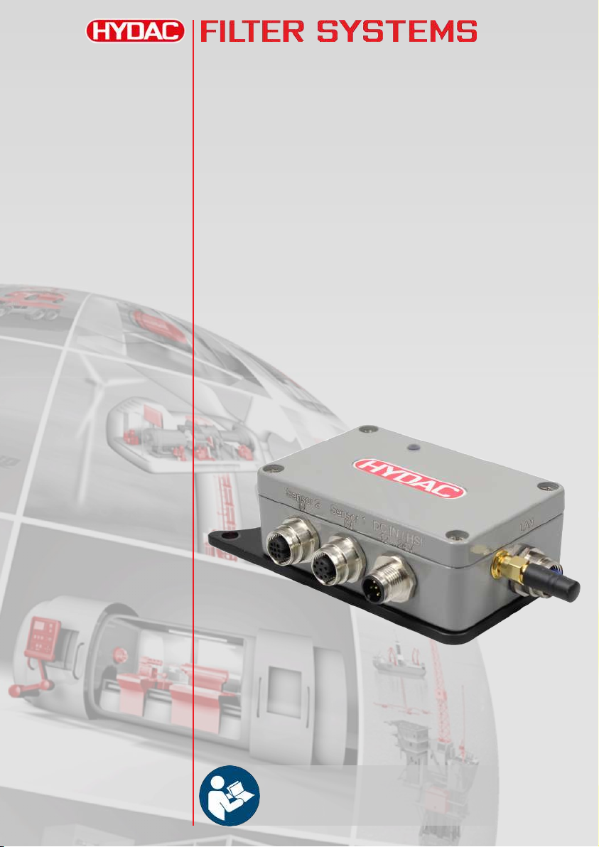
CSI-C-11
ConditionSensor Interface
Operating Instruction
English • (translation of original instructions)
Document No. : 4191469a • 3/19/2019
Follow these instructions for proper and safe use.
Keep for future reference.
Valid from firmware versions up V 2.30
Page 2

Table of Contents
HYDAC FILTER SYSTEMS GMBH
Table of Contents
1 General ..................................................................................................................... 4
1.1 Imprint ..............................................................................................................4
1.2 Documentation Representative........................................................................ 4
1.3 Purpose of this manual .................................................................................... 5
1.4 Target group of the manual.............................................................................. 5
1.5 Target group - Required qualifications/training ................................................ 6
1.6 Illustrations in the manual ................................................................................ 7
1.6.1 Illustration on the title page.................................................................. 7
1.6.2 Representation of requirements .......................................................... 8
1.6.3 Representation of procedural instructions ........................................... 8
1.6.4 Representation of intermediate results/results .................................... 9
1.6.5 Representation of warning/general safety information ...................... 10
1.6.6 Signal words and their meaning in the safety information and instruc-
tions ................................................................................................... 11
1.7 Representation/explanation of pictograms..................................................... 12
1.8 Supplementary symbols................................................................................. 13
1.9 Exclusion of liability/warranty ......................................................................... 13
1.10 Notes on copyright ......................................................................................... 14
1.11 Validity of this manual .................................................................................... 14
2 General safety information ...................................................................................... 15
3 Product overview..................................................................................................... 17
3.1 Scope of delivery............................................................................................ 18
3.2 Dimensions .................................................................................................... 19
3.3 Proper/Designated Use.................................................................................. 20
3.4 Improper Use or Use Deviating from Intended Use ....................................... 21
3.5 Technical Data ............................................................................................... 22
3.6 Decoding the model code label...................................................................... 24
3.6.1 Model code ........................................................................................ 25
4 Storage and transport ............................................................................................. 26
ii Bewa CSI-C-11 4191469a en-us lq
Page 3

HYDAC FILTER SYSTEMS GMBH Table of Contents
5 Assembly, installation and commissioning.............................................................. 27
5.1 Assembling the CSI........................................................................................ 27
5.2 Connection overview...................................................................................... 29
5.2.1 Pin assignment – DC IN / HSI............................................................ 30
5.2.2 Pin assignment – Sensor 1 IN ........................................................... 30
5.2.3 Pin assignment – Sensor 2 IN ........................................................... 31
5.2.4 Pin assignment - LAN........................................................................ 31
5.2.5 Connection examples ........................................................................ 32
5.3 Commissioning............................................................................................... 34
5.3.1 Parametrizing the CSI ....................................................................... 34
5.3.2 Parameterizing the CSI via FluMoS mobile (Android) ....................... 34
6 Factory settings....................................................................................................... 35
6.1 Description of the factory settings .................................................................. 35
6.2 Overview of the factory settings ..................................................................... 37
7 Operation ................................................................................................................ 39
7.1 Evaluating/reading measurement protocols/values ....................................... 40
7.1.1 Evaluating/reading measurement reports/values with FluMoS ......... 40
7.1.2 Reading measurement protocols/values via Modbus........................ 41
7.1.2.1 Mapping - new format ............................................................... 42
7.1.2.2 Mapping -old format.................................................................. 44
7.1.2.3 Example with CS1000 / AS1000............................................... 46
7.1.3 Reading measurement protocols/values via FluMoT ........................ 47
8 Maintenance............................................................................................................ 48
9 Troubleshooting/fault rectification ........................................................................... 49
10 Removing / Disposal ............................................................................................... 51
11 Appendix ................................................................................................................. 52
11.1 Accessories.................................................................................................... 52
Glossary .................................................................................................................. 58
Index ....................................................................................................................... 60
Bewa CSI-C-11 4191469a en-us lq iii
Page 4

1 | General HYDAC FILTER SYSTEMS GMBH
1 General
In this chapter, you will find helpful notes on handling these instructions.
1.1 Imprint
Manufacturer / publisher and responsible for the content:
Address of the manufacturer Contact address
HYDAC FILTER SYSTEMS
GMBH
Industriegebiet
66280 Sulzbach / Saar
Germany Germany
E-mail: [email protected]
Homepage: www.hydac.com
Court of Registration: Saarbrücken , HRB 17216
Executive director: Mathias Dieter ,
Tab.1:
Impressum
HYDAC FILTER SYSTEMS
GMBH
Justus-von-Liebig-Str., Werk
20
66280 Sulzbach / Saar
Dipl.Kfm. Wolfgang Haering
1.2 Documentation Representative
The contact data of the person authorized with the documentation is:
Mr. Günter Harge
c/o HYDAC International GmbH, Industriegebiet, 66280
Sulzbach / Saar
Germany
Phone: +49 6897 509 1511
Fax: +49 6897 509 1394
E-mail: [email protected]
Tab.2:
Documentation Representative
4 / 64 Bewa CSI-C-11 4191469a en-us lq
Page 5

HYDAC FILTER SYSTEMS GMBH General | 1
1.3 Purpose of this manual
Before you use this product for the first time or if you have
been asked to carry out other work on the product, please read
this manual.
The use and the handling of the product described in the following, as well as its use, are not self-explanatory and are described in detail in this manual and the associated technical
documentation.
This manual will help you to use the product as intended, properly, effectively, and safely. Therefore, you are requested to
read the following chapters attentively and carefully. Please refer to it every time you require decisive details.
This manual informs and warns you of risks, against which the
risk reduction through the design and protective measures may
not be effective or not fully effective.
1.4 Target group of the manual
This manual was created for the following target group.
Target group Tasks
Owner This manual and the associated docu-
ments must be kept accessible at the installation location and also for later use.
Ask the employees to read and follow the
manual and the associated documents, in
particular, the safety and warning instructions.
Observe the additional product-related instructions and requirements.
Specialist personnel
Read, observe and follow this manual and
the associated documents, in particular,
the safety and warning instructions.
Tab.3:
Target group
Bewa CSI-C-11 4191469a en-us lq 5 / 64
Page 6

1 | General HYDAC FILTER SYSTEMS GMBH
1.5 Target group - Required qualifications/training
Persons who work on the equipment must be aware of the
hazards associated with its use.
These operating instructions are intended for:
Auxiliary personnel:
Such persons have been instructed about the
sensor and informed about potential hazards
that can result from improper use.
Specialist personnel:
Such persons have corresponding specialist
training and several years' work experience.
They are able to assess and perform the
work assigned to them, they are also able to
recognize potential dangers.
Life phase Person Required knowledge
Transport /
Storage
Electrical installation,
commissioning,
Auxiliary
personnel
Specialist
electrician
No specialist knowledge required.
Safe handling/use of tools.
Fitting and connection of
electrical lines.
troubleshooting,
decommissioning
Knowledge of network communication.
Knowledge of using Windows
PCs and of program installation.
Product-specific knowledge.
Operation,
operations control
Specialist Knowledge of using Windows
PCs/mobile end devices.
Product-specific knowledge.
Dismantling,
disposal
Specialist Proper and environmentally
friendly disposal of materials
and substances.
Knowledge about reuse.
Tab.4:
Required qualifications/training
6 / 64 Bewa CSI-C-11 4191469a en-us lq
Page 7
HYDAC FILTER SYSTEMS GMBH General | 1
Short name of the product
Product name
Operating and Maintenance Instructions
12345678 ● ##.##.####
English (translation of original instructions)
Valid from:
- from s/no.
- ... ...
- ... ...
1
5
2
4
3
1.6 Illustrations in the manual
You will find illustrations in this manual. You can find details regarding these in the following chapters.
1.6.1 Illustration on the title page
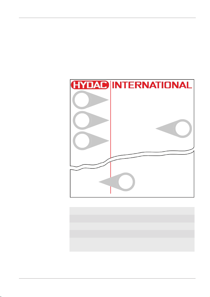
You will find the following information on the title page of this
manual:
Bewa CSI-C-11 4191469a en-us lq 7 / 64
Fig.1:
Overview / labeling of the title page
1 Short name of the product / product name
2 Type of document
3 Language
4 Document no./Index ● Date of printing
5 Supplementary instructions regarding the validity of the
manual (optional)
Page 8
1 | General HYDAC FILTER SYSTEMS GMBH
Please note that you can directly access information
through the directories. However, this does not release you from the obligation to read this manual
fully before commissioning.
The document no. with the index (4) is meant for identifying
and reordering the manual. The index is incremented every
time the manual is revised or changed.
The manual contains a table of contents, a list of tables and
figures, an index and a glossary.
1.6.2 Representation of requirements
These are absolutely required for carrying out a work activity
on the product and are marked with a check mark and are in
bold in the text.
An example for the representation of requirements:
ü The product is assembled and connected.
ü The product is switched off.
1. Switch the product on.
1.6.3 Representation of procedural instructions
In the case of procedural instructions, there are the two following representations:
Procedural instructions with a fixed sequence
Procedural instructions, whose sequence must be complied
with without fail, are listed with sequential numbering (1., 2., 3.,
etc.).
An example for procedural instructions with a fixed sequence:
1. Remove the transport securing device.
2. First fill the product.
3. Switch the product on.
8 / 64 Bewa CSI-C-11 4191469a en-us lq
Page 9

HYDAC FILTER SYSTEMS GMBH General | 1
Procedural instructions with a random sequence
Procedural instructions that have a random sequence are
listed as bullet points (-).
An example of a procedural instruction with a random sequence:
– Clean the display.
– Rinse the product.
1.6.4 Representation of intermediate results/results
In the case of some activities, it is necessary to carry out work
steps with intermediate results and end results.
Intermediate results are the consequence of activities; they are
marked with an indented arrow.
End results represent the end of an activity and are represented with a flag.
An example for a procedural instruction with intermediate result and final result:
1. Switch the product on.
ð The display lights up.
2. Press the button.
O The product is now ready for use.
Bewa CSI-C-11 4191469a en-us lq 9 / 64
Page 10
1 | General HYDAC FILTER SYSTEMS GMBH
CAUTION
Type and source of danger
Hazard symbol
Consequence of the danger
Measures to avert danger
►
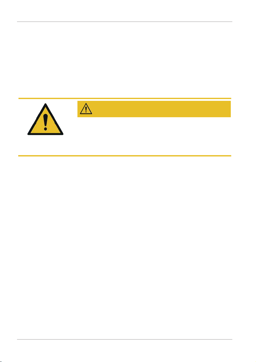
1.6.5 Representation of warning/general safety information
All the warning / general safety information in this manual are
highlighted with pictograms and signal words. The pictogram
and the signal word give you an indication of the severity of the
danger.
Warning / general safety information, which are placed ahead
of each activity, are represented as follows:
10 / 64 Bewa CSI-C-11 4191469a en-us lq
Page 11
HYDAC FILTER SYSTEMS GMBH General | 1
DANGER
WARNING
CAUTION
NOTICE
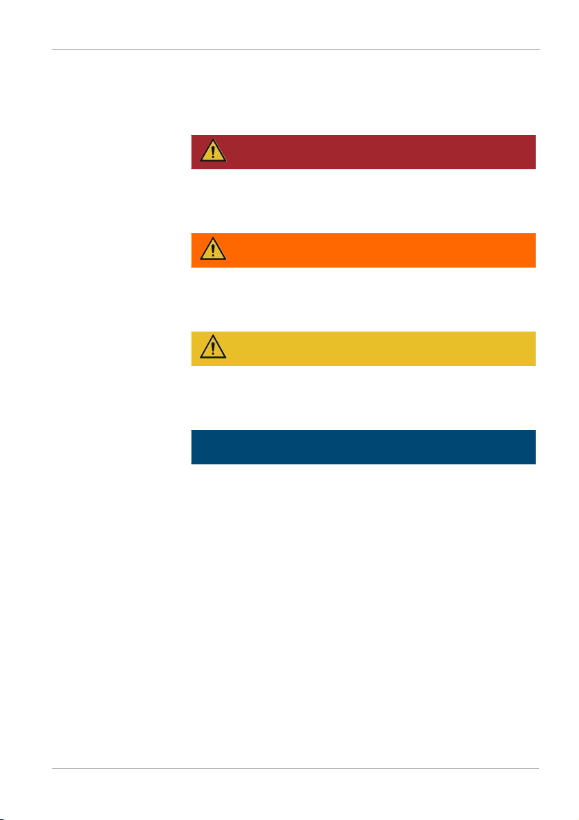
1.6.6 Signal words and their meaning in the safety information and instructions
In these instructions you will find the following signal words:
DANGER – The signal word indicates a hazardous situation
with a high level of risk, which, if not avoided, will result lethal
or serious injury.
WARNING – The signal word indicates a hazardous situation
with a medium level of risk, which, if not avoided, can result
lethal or serious injury.
CAUTION – The signal word indicates a hazardous situation
with a low level of risk, which, if not avoided, can result in minor or moderate injury.
NOTICE – The signal word indicates a hazardous situation
with a high level of risk, which, if not avoided, will result in
damage to property.
Bewa CSI-C-11 4191469a en-us lq 11 / 64
Page 12
1 | General HYDAC FILTER SYSTEMS GMBH
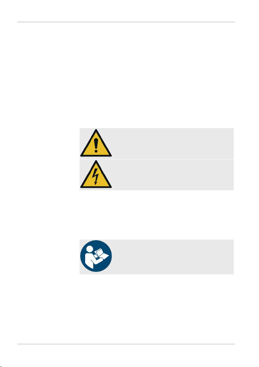
1.7 Representation/explanation of pictograms
The following are the safety symbols / pictograms in this manual. They indicate specific dangers to persons, property or to
the environment. Observe these safety symbols / pictograms
and act with particular caution in such cases. Always keep all
symbols / pictograms intact and legible.
Warning signs used
These signs are listed for all safety information and instructions
in these operating instructions which indicate particular hazards to persons, property or the environment.
Danger point warning
Dangerous electrical voltage warning
Signs used for giving orders
These symbols are listed for all safety information and instructions in these operating instructions which indicate particular
hazards to persons, property or the environment.
Follow the instructions.
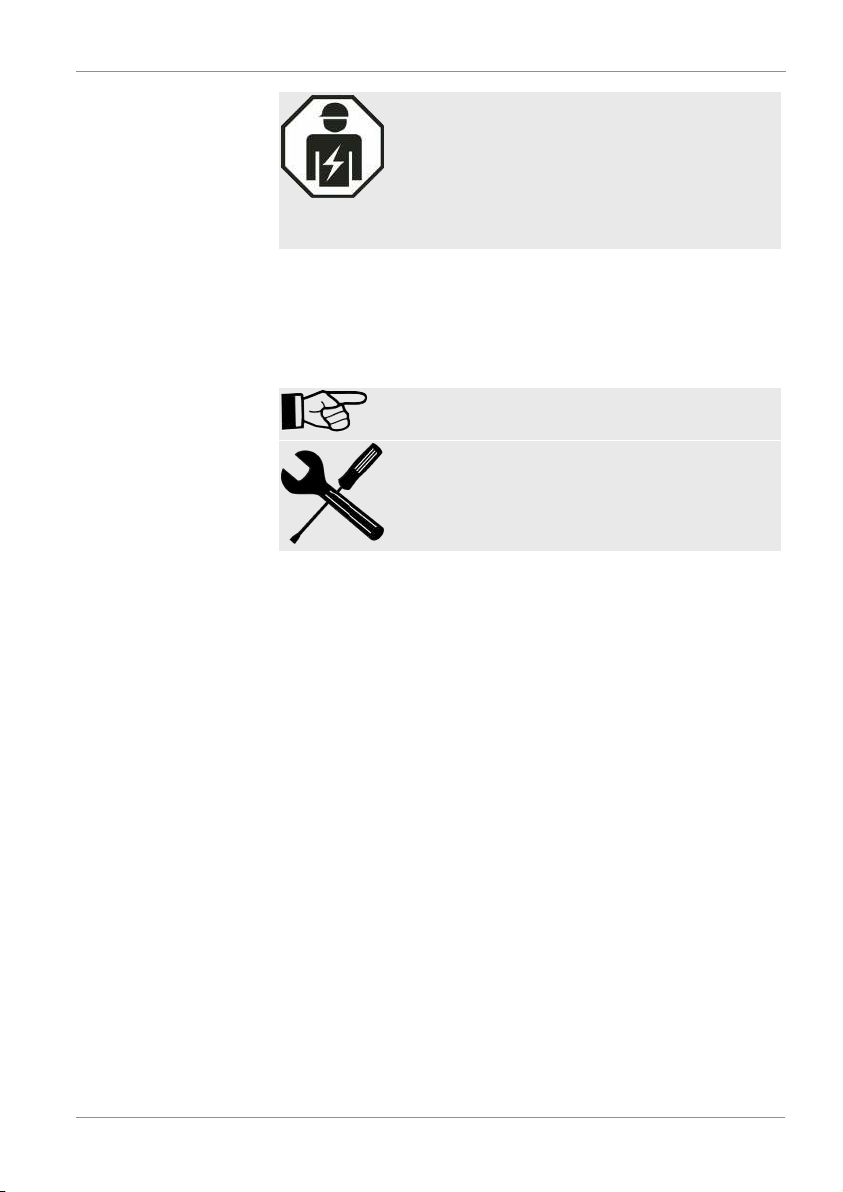
Signs used for the required specialist personnel
These symbols show the required training/knowledge for installation work and/or maintenance work.
12 / 64 Bewa CSI-C-11 4191469a en-us lq
Page 13
HYDAC FILTER SYSTEMS GMBH General | 1
Specialist personnel - Electrician
Such persons have specific specialist training
and several years' work experience. They are
able to assess and perform the work assigned to
them, they are also able to recognize potential
hazards.
1.8 Supplementary symbols
You will find the following symbols in the manual as additional
details:
Tip for handling the product
Required tools
1.9 Exclusion of liability/warranty
For the warranty provided by us, please refer to the Terms of
Delivery. They are made available to you at the conclusion of
the contract at the latest. You will also find these under
www.hydac.com -> General Terms and Conditions (T&C).
This manual was prepared to the best of our knowledge. Nevertheless and despite the greatest care taken, it may contain
errors. Therefore, please understand that, in the absence of
any provisions to the contrary hereinafter, our warranty and liability – for any legal reasons whatsoever – are excluded in respect of the information in this manual. In particular, we shall
not be liable for lost profit or other financial loss.
This exclusion of liability does not apply in cases of intent and
gross negligence. Moreover, it does not apply to defects which
have been deceitfully concealed or whose absence has been
guaranteed, nor in cases of culpable harm to life, physical injury and damage to health. If we negligently breach any mate-
Bewa CSI-C-11 4191469a en-us lq 13 / 64
Page 14

1 | General HYDAC FILTER SYSTEMS GMBH
rial contractual obligation, our liability shall be limited to foreseeable damage. Claims due to the Product Liability shall remain unaffected.
1.10 Notes on copyright
All rights to this documentation, in particular to the right to reproduction and distribution, as well as to the translation, are
property of HYDAC FILTER SYSTEMS GMBH.
Distributing and copying this document and utilizing and disclosing its content is not permitted, except where this has been
agreed upon explicitly. Any infringement will entail liability for
damages. All rights reserved in the case of a patent being
granted or a utility model or the design being registered.
1.11 Validity of this manual
The diagrams and visualizations in this manual are meant for
general illustration purposes. Therefore, representations and
functional options can deviate from the delivered product.
We reserve the right to changes to the contents of this manual
without prior notice.
14 / 64 Bewa CSI-C-11 4191469a en-us lq
Page 15
HYDAC FILTER SYSTEMS GMBH General safety information | 2
2 General safety information
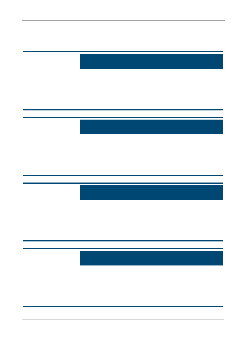
The following residual risks can occur through intended use:
NOTICE
Identical bus addresses of SMART sensors
Erroneous or no communication.
u
Take note of different bus addresses of the HYDAC
SMART sensors.
NOTICE
Wrong sensor
Erroneous or no communication.
u
Connect the CSI-C-11 only with HYDAC SMART sensors
or the permitted analog sensors.
NOTICE
Connecting more than two HYDAC SMART sensors
Erroneous or no communication.
u
Connect a maximum of two HYDAC SMART sensors to
the CSI-C-11.
NOTICE
Connection of more than 4 permitted analog sensors
Erroneous or no communication.
u
Connect a maximum of 4 permitted analog sensors to the
CSI-C-11.
Bewa CSI-C-11 4191469a en-us lq 15 / 64
Page 16

2 | General safety information HYDAC FILTER SYSTEMS GMBH
NOTICE
Exceeding the maximum permissible line length
Erroneous or no communication.
u
Observe the maximum permissible line lengths.
16 / 64 Bewa CSI-C-11 4191469a en-us lq
Page 17

HYDAC FILTER SYSTEMS GMBH Product overview | 3
3 Product overview
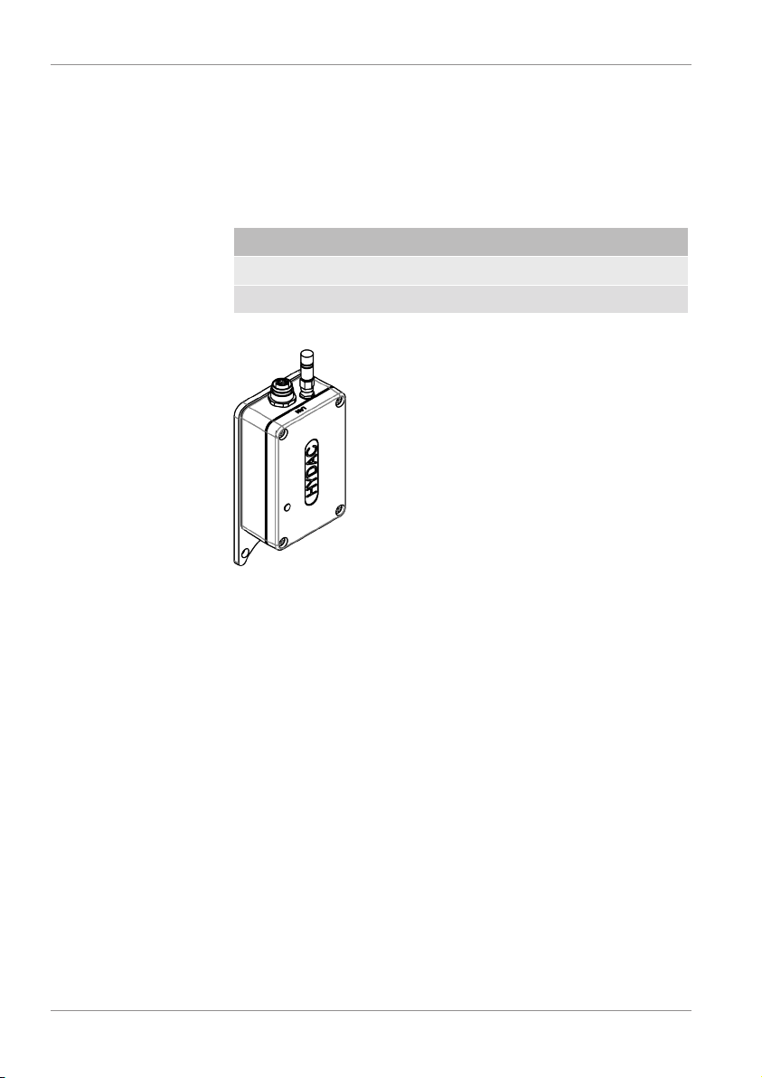
The ConditionSensor Interface CSI-C-11 is used for the implementation of digital and analog sensor signals of HYDAC sensors in network and field bus protocols (e.g. Modbus®) for either cable-connected (LAN) or wireless (WLAN) transmission
to stationary (e.g. desktop PC) and mobile end devices (e.g.
smartphone). In addition, the CSI-C-11 has an internal memory
through which the interface module can also be used as a data
logger.
Depending on the device type, up to two HYDAC SMART sensors and four analog sensors can be connected to the interface module and supplied with voltage. Furthermore, the
CSI-C-11 is equipped with a fieldbus/ethernet interface that enables the integration of connected sensors into company networks or a higher-level ConditionMonitoringSystem CMS and
control systems (SPS) and process control systems (SCADA).
The special features of the CSI-C-11 include:
– 2 input channels for HYDAC SMART sensors
– 4 input channels for analog sensors (optional)
– Direct connection of the sensors via M12x1 connectors
– Simple network and system integration/field bus integra-
tion via network connection (M12x1)
– Wireless transfer and display of sensor measured values
via WLAN and FluMoS/FluMoS mobile
– Measured data storage in CSI-C-11 with date and time
(data logger)
– Parametrization of the interface (e.g. IP address, subnet
mask) possible via WLAN and FluMoS mobile
– Integrated assembly plate for wall mounting or directly on
the HYDAC ConditionSensor Module CSM Economy
– Compact design for space-saving assembly
– High protection class with IP66, no need for switch cabi-
net
Bewa CSI-C-11 4191469a en-us lq 17 / 64
Page 18
3 | Product overview HYDAC FILTER SYSTEMS GMBH
3.1 Scope of delivery
The ConditionSensorInterface comes packed, factory-assembled, and preset. Before starting up the CS-C-11, check that
the content of the package is complete.
The following items are supplied:
Qty Designation
1 ConditionSensorInterface CSI-C-11
1 Operating Instruction (this document)
Tab.5:
Scope of delivery
18 / 64 Bewa CSI-C-11 4191469a en-us lq
Page 19
HYDAC FILTER SYSTEMS GMBH Product overview | 3
3.2 Dimensions
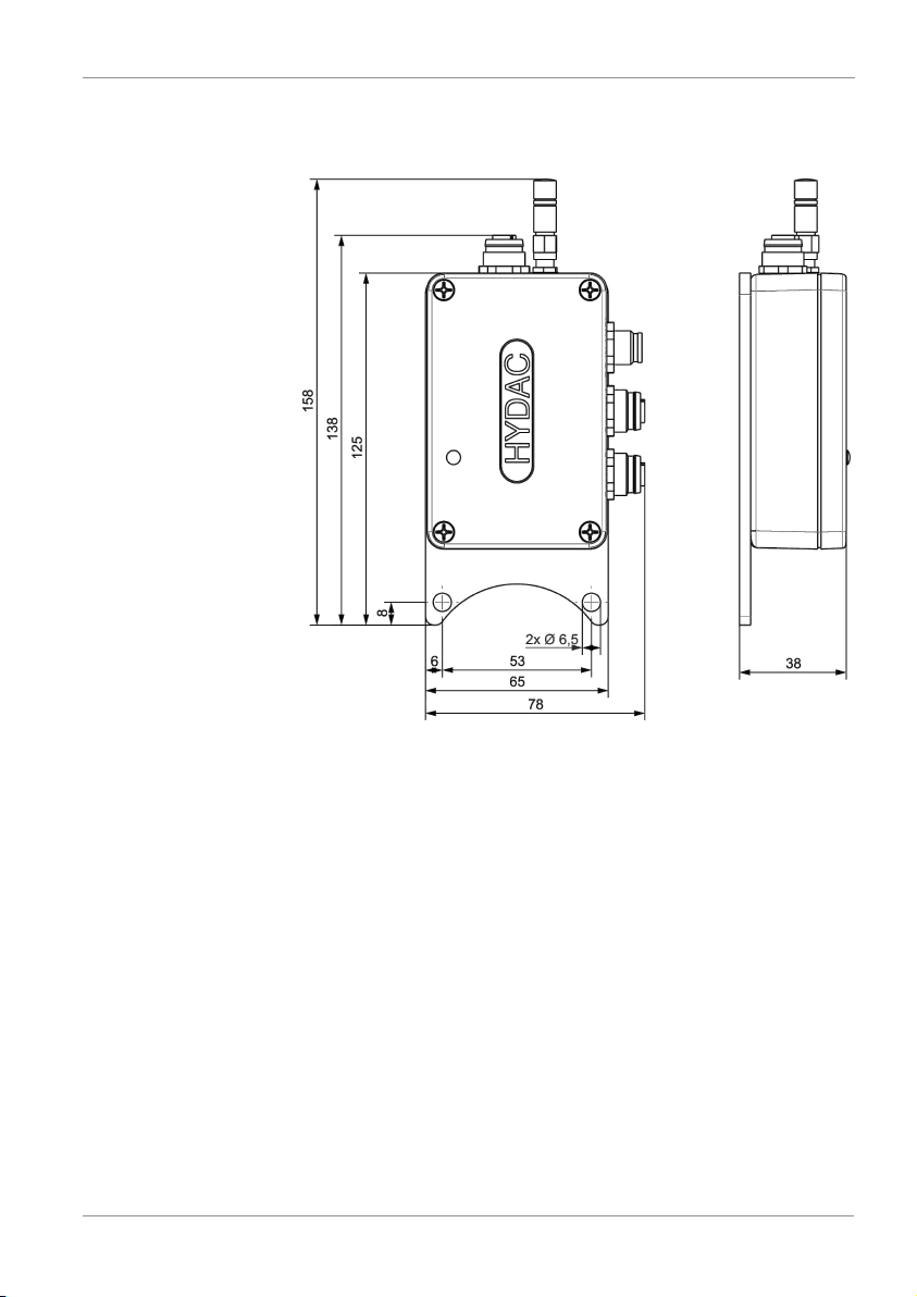
The CSI-C-11 has the following dimensions.
Fig.2:
CSI-C-11 dimensions
All dimensions in mm.
Bewa CSI-C-11 4191469a en-us lq 19 / 64
Page 20

3 | Product overview HYDAC FILTER SYSTEMS GMBH
3.3 Proper/Designated Use
Use the ConditionSensorInterface CSI-C-11 only for the application described in the following.
Depending on the device type, the ConditionSensorInterface
CSI-C-11 serves to implement digital (HYDAC SMART sensors with the HydacSensorInterface HSI) and analog sensor
signals (e.g. 4 - 20 mA) in multiple network protocols (e.g.
HSITCP/IP and Modbus® TCP), and field bus protocols (e.g.
Modbus® RTU) which can be transmitted both by cable (LAN)
and wirelessly (WLAN) to stationary (e.g. desktop PC) and mobile end devices (e.g. smartphone). In addition, the CSI-C-11
has an internal memory through which the interface module
can also be used as a data logger. Depending on the type of
device, for example, two HYDAC SMART sensors and four
analog sensors can be connected.
For example:
Permitted HYDAC SMART sensors (digital):
– CS1000 Series
– AS1000 Series
– MetallicContaminationsensor MCS1000 series
– HYDACLab HLB1000 series
Permitted analog sensors with an analog output:
– 4-20mA (load =500Ω)
– 0-20mA (load =500Ω)
– 0…10VDC
– 0…5VDC
– 2…10VDC
– 1…5VDC
– Example: Temperature measurement transformer,
pressure measurement transformer, differential pressure sensors, volumetric flow sensors or level sensors
20 / 64 Bewa CSI-C-11 4191469a en-us lq
Page 21

HYDAC FILTER SYSTEMS GMBH Product overview | 3
3.4 Improper Use or Use Deviating from Intended Use
Improper use or use deviating from intended may result in hazards and/or will damage the sensor. Examples of improper use
or use deviating from intended use include:
– Operation with non-approved sensors.
– Operation with more than two HYDAC SMART sensors.
– Operation with more than four analog sensors.
– Modifications to the interface made by the user or pur-
chaser.
Bewa CSI-C-11 4191469a en-us lq 21 / 64
Page 22

3 | Product overview HYDAC FILTER SYSTEMS GMBH
3.5 Technical Data
The CSI-C-11 has the following technical data:
HSI interface HYDACSensorInterface for
the connection of two
HYDAC SMART sensors
Analog interface Sensor interface for the con-
nection of a maximum of four
analog sensors (type selectable):
- 4-20mA (load: 500Ω)
- 0-20mA (load: 500Ω)
- 0-10V
- 0-5V
- 2-10V
- 1-5V
measurement accuracy
<0.2%FS (FullScale)
Tab.6:
Input data
Ethernet:
10 Base-T / 100 Base-TX
WLAN (only HSI):
Protocols:
- HSI TCP/IP (Port 49322)
- Modbus® TCP (Port 502)
2.4GHz, IEEE 802.11 b/g/n
RS485:
2-wire, half-duplex
Tab.7:
Outputs
Protocol:
- Modbus® RTU
Power supply 12 … 24 VDC ±10%
Current consumption 100 mA
in addition to the connected
sensors, sensor supply 1224VDC (looped through)
Power supply Connector, M12, 5-pin, male
HYDAC SMART sensor 1 and
Bushing, M12, 8-pin, female
analog sensors 1-4:
HYDAC SMART sensor 2 Bushing, M12, 5-pin, female
22 / 64 Bewa CSI-C-11 4191469a en-us lq
Page 23

HYDAC FILTER SYSTEMS GMBH Product overview | 3
LAN Bushing, M12, 4-pin, D en-
coded
(acc. to IEC61076-2-101)
WLAN antenna RP-SMA bushing
Parameterization Via device connector M12x1,
5-pin, according to
DINVDE0627 or WLAN with
FluMoS mobile or LAN with
FluMoS professional
Tab.8:
Electrical data
Variable 64 MB
Storage interval @ 60 seconds
>1300 days (at CS1000 +
HLB1400)
Storage interval @ 60 minutes >83000 days (at CS1000 +
HLB1400)
Tab.9:
Internal measurement data memory
Permitted ambient tempera-
-25…85 °C
ture range
Permissable relative humidity 0 - 70%, non-condensing
Permitted storage temperature
-30…85 °C
range
Protection class in accordance
IP66
with DIN 40050
Housing dimensions 131 x 77.5 x 35.5 mm
Body Aluminum housing
Weight ≈ 360 g
Tab.10:
Bewa CSI-C-11 4191469a en-us lq 23 / 64
Other data
Page 24
3 | Product overview HYDAC FILTER SYSTEMS GMBH
3.6 Decoding the model code label
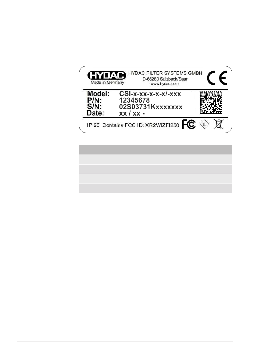
For identification details of the CSI, see the type label. Always
mention the part no. and the serial no. when contacting
HYDAC.
Fig.3:
Type label
Row Description
Model For details, see Model code [}25]
P/N Part no.
S/N Serial number
Date Year/week of production - hardware index
Tab.11:
Decoding the model code label
24 / 64 Bewa CSI-C-11 4191469a en-us lq
Page 25

HYDAC FILTER SYSTEMS GMBH Product overview | 3
Product series
Signal output (report) 1
Body
CSI - C - 11 - 0 - 0 - 0 /- 000
Signal output (report) 2
Signal input
CSI = ConditionSensor Interface
11 = Ethernet (Modbus TCP, HSI TCP/IP),
C = Metal housing, compact
Modification
Signal output (report) 3
0 = 2x HSI
1 = 2x HSI + 4x analog
WLAN (HSI TCP/IP)
0 = RS485 (Modbus RTU)
000 = Standard
0 = without
®
®
3.6.1 Model code
The CSI-C-11 has the following model code:
Fig.4:
Model code CSI-C-11
Bewa CSI-C-11 4191469a en-us lq 25 / 64
Page 26

4 | Storage and transport HYDAC FILTER SYSTEMS GMBH
4 Storage and transport
Please transport the CSI packed in the packaging supplied.
Store the CSI in a clean, dry place, in the supplied packaging
as far as is possible. Only remove the packing just before installing the unit.
Observe the storage conditions given in Chapter Technical
Data [}22].
26 / 64 Bewa CSI-C-11 4191469a en-us lq
Page 27
HYDAC FILTER SYSTEMS GMBH Assembly, installation and commissioning | 5
5 Assembly, installation and commissioning
This chapter provides information on assembly, installation and
commissioning.
5.1 Assembling the CSI
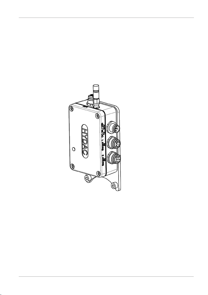
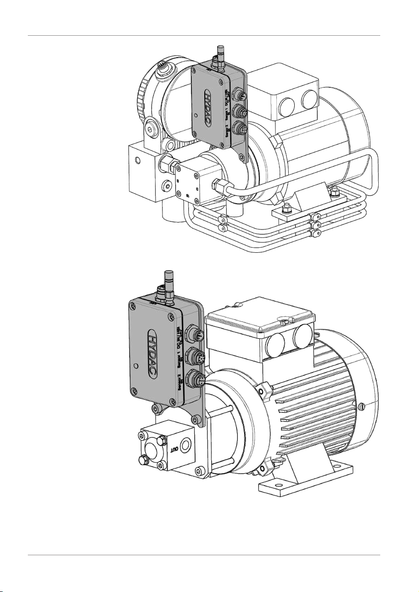
The CSI-C-11 has an assembly plate with two boreholes for
wall mounting or mounting on an electric motor. The position of
the CSI can be as required while doing this.
Fig.5:
Assembling the CSI-C-11
This mounting plate is also meant for direct mounting on the
HYDAC ConditionSensor Module CSM Economy.
Bewa CSI-C-11 4191469a en-us lq 27 / 64
Page 28
5 | Assembly, installation and commissioning HYDAC FILTER SYSTEMS GMBH
Fig.6:
Example: CSI-C-11 assembled on a CSM-E
Fig.7:
Example: CSI-C-11 assembled on a motor-pump assembly
28 / 64 Bewa CSI-C-11 4191469a en-us lq
Page 29
HYDAC FILTER SYSTEMS GMBH Assembly, installation and commissioning | 5
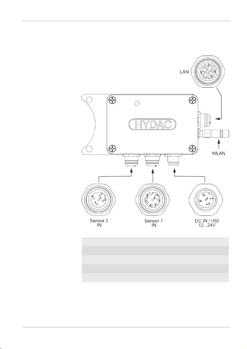
5.2 Connection overview
Connect the CSI-C-11 to the sensors and the power supply as
shown below.
Fig.8:
Connection overview
LAN Local Area Network
WLAN Wireless Local Area Network
Sensor 2 IN Sensor 2
Sensor 1 IN Sensor 1
DC IN / HSI Power supply
Bewa CSI-C-11 4191469a en-us lq 29 / 64
Page 30
5 | Assembly, installation and commissioning HYDAC FILTER SYSTEMS GMBH
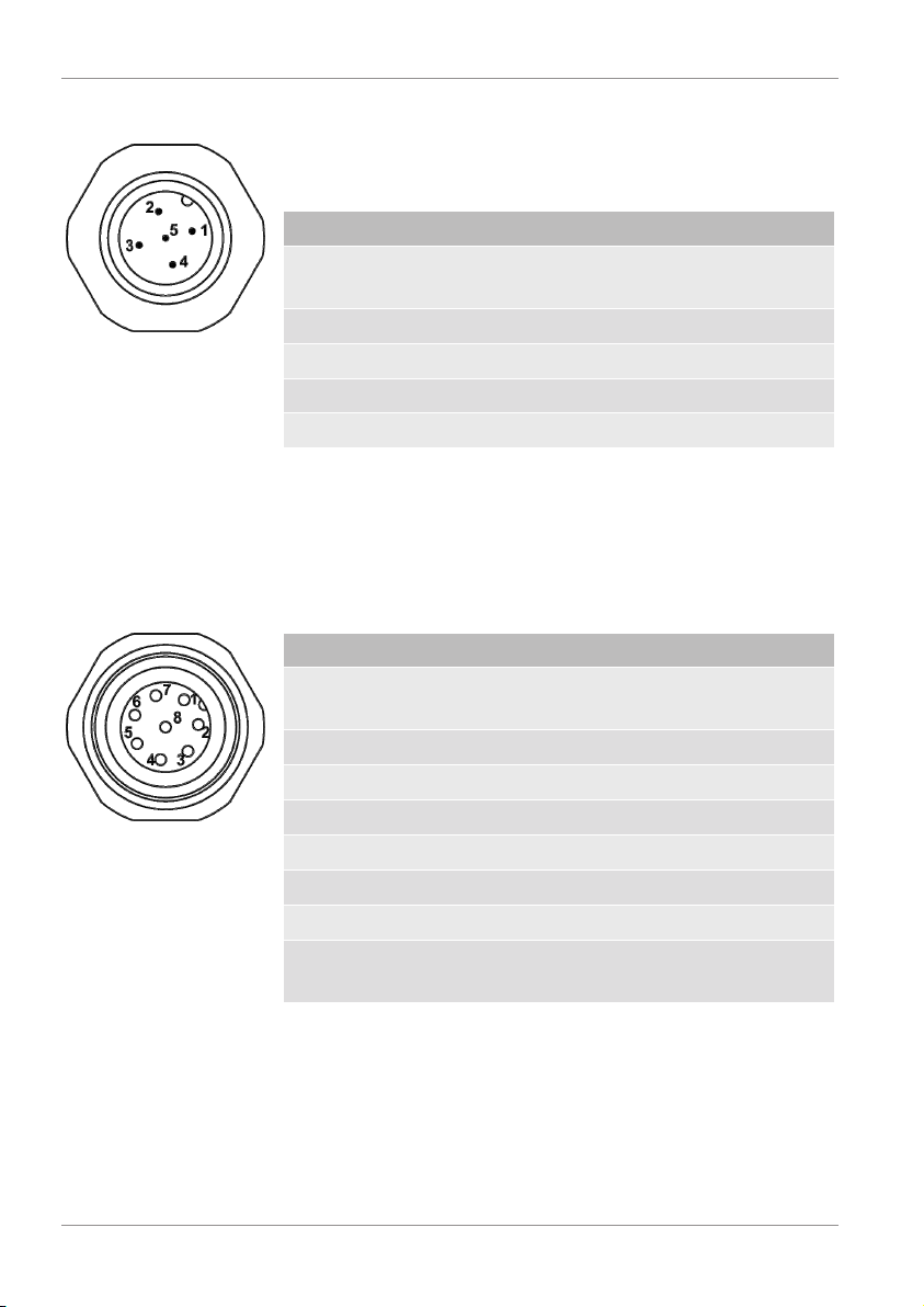
5.2.1 Pin assignment – DC IN / HSI
The connection socket DC IN / HSI has the following pin assignment.
Pin Signal Description
1 DCIN
Supply voltage +
12…24VDC
2 RS485 - Modbus RTU
Fig.9:
DC IN / HSI
3 GND Supply voltage GND
4 RS485 + Modbus RTU
5 HSI Parameterization
Tab.12:
Pin assignment – DC IN / HSI
5.2.2 Pin assignment – Sensor 1 IN
The connection socket Sensor 1 IN has the following pin assignment.
Pin Signal Description
Fig.10:
Sensor 1 IN
1 S1
12…24VDC
2 A1 Analog sensor 1 Analog input 1
3 S1 GND SMART sensor 1 GND supply voltage
4 A2 Analog sensor 2 Analog input 2
5 S1 HSI SMART sensor 1 HSI signal input
6 A3 Analog sensor 3 Analog input 3
7 A4 Analog sensor 4 Analog input 4
8 A1 – A4 GND Analog sensor
Tab.13:
Pin assignment – Sensor 1 IN
SMART sensor 1 + Supply voltage
Analog input GND
1-4
30 / 64 Bewa CSI-C-11 4191469a en-us lq
Page 31
HYDAC FILTER SYSTEMS GMBH Assembly, installation and commissioning | 5
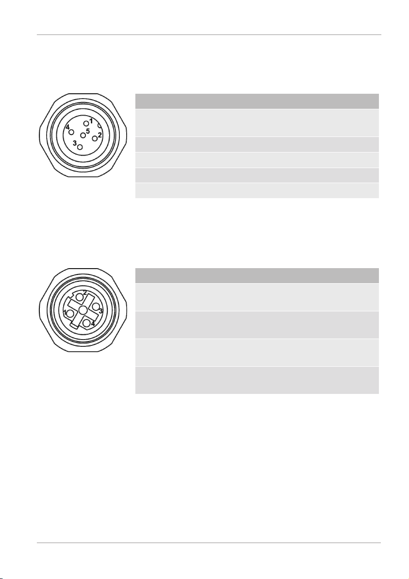
5.2.3 Pin assignment – Sensor 2 IN
The connection socket Sensor 2 IN has the following pin assignment.
Pin Signal Description
3.1 S2
SMART sensor 2 + Supply voltage
12…24VDC
3.2 - - not allocated
3.3 S2 GND SMART sensor 2 GND supply voltage
3.4 - - not allocated
Fig.11:
Sensor 2 IN
3.5 S2 HSI SMART sensor 2 HSI signal input
Tab.14:
Pin assignment – Sensor 2 IN
5.2.4 Pin assignment - LAN
The LAN connection socket has the following assignment.
Pin Signal Description
1 ETH TX+ Network (LAN) Ethernet port for data
transmission +
2 ETH RX+ Network (LAN) Ethernet port for re-
ceiving data +
3 ETH TX- Network (LAN) Ethernet port for data
Fig.12:
LAN
4 ETH RX- Network (LAN) Ethernet port for re-
Tab.15:
Pin assignment - LAN
transmission -
ceiving data -
Bewa CSI-C-11 4191469a en-us lq 31 / 64
Page 32
5 | Assembly, installation and commissioning HYDAC FILTER SYSTEMS GMBH
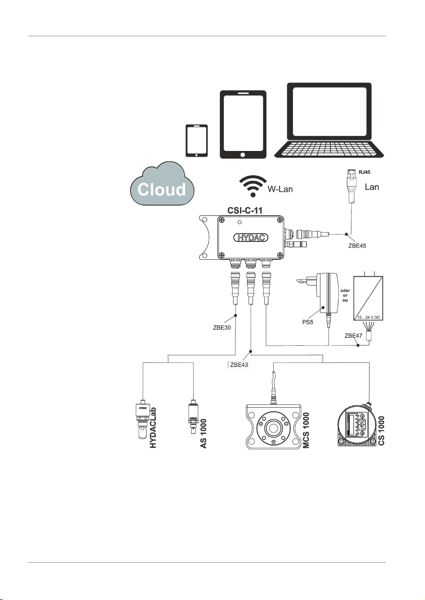
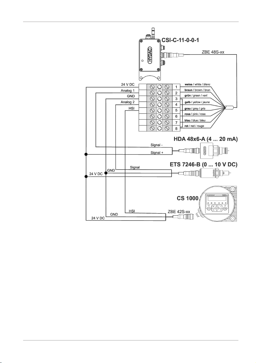
5.2.5 Connection examples
Here, you will find connection examples for the CSI-C-11.
Fig.13:
Connection example CSI-C-11-0-0-0
32 / 64 Bewa CSI-C-11 4191469a en-us lq
Page 33
HYDAC FILTER SYSTEMS GMBH Assembly, installation and commissioning | 5
Fig.14:
Connection example CSI-C-11 - CS1000 - HDA48x6-A -
ETS7246-B
Bewa CSI-C-11 4191469a en-us lq 33 / 64
Page 34

5 | Assembly, installation and commissioning HYDAC FILTER SYSTEMS GMBH
5.3 Commissioning
Parametrize the CSI before operation according to the following chapter.
5.3.1 Parametrizing the CSI
In order to connect the CSI to the network environment, adjust
the factory settings such as the IP address, subnet mask,
SSID, and the communication of the connected sensors to
your requirements/conditions.
5.3.2 Parameterizing the CSI via FluMoS mobile (Android)
In order to parametrize the CSI via FluMoS mobile, load the
app for the Android operating system from the
Google Play Store and install it on your mobile end device.
Then, establish a connection to your mobile end device via
WLAN. The CSI answers with the SSID: HYDAC_AP (factory
setting).
When the connection is established, you can make all the required settings in the dialog menu.
34 / 64 Bewa CSI-C-11 4191469a en-us lq
Page 35

HYDAC FILTER SYSTEMS GMBH Factory settings | 6
6 Factory settings
The CSI is delivered with the following factory settings.
6.1 Description of the factory settings
You will find a description of the settings and the limit values
here.
Menu item Description
SmartSensor Count Number of the connected
HYDAC SMART sensors
Device Address HSI bus address of the CSI
Save Time (s) Storage interval for the data logger (1-
65535 seconds).
SSID Name of the access point (maximum 31
characters).
Security WLAN encryption can be switched on
(WPA2).
Key Password for encryption (maximum 15
characters).
IP IP address of the LAN connection.
Subnet Subnet mask for the LAN connection.
Gateway Standard gateway for the LAN connec-
tion.
Time (hh:mm:ss) Time for the data logger.
Date (dd/mm/yy) Date for the data logger.
Analog 1-4 Parametrizing the connected analog
sensors.
Channel Type Analog channel type can be selected
between:
-OFF
- 4-20mA,
- 0-20mA,
- 0-10V
Bewa CSI-C-11 4191469a en-us lq 35 / 64
Page 36

6 | Factory settings HYDAC FILTER SYSTEMS GMBH
Menu item Description
- 0-5V
- 2-10V,
- 1-5V
Name Name of the analog channel.
Unit Unit of the analog channel.
Lower Range Minimum value of the analog channel.
Upper Range Maximum value of the analog channel.
Modbus ID 1
Register offset 0
Format Reading out measurement protocols/
values via Modbus [}41]
Baud rate 19200
Parity None
Data bits 8
Stop bits 1
Input register map-
Example with CS1000/AS1000 [}46]
ping
Tab.16:
Description of the factory settings
36 / 64 Bewa CSI-C-11 4191469a en-us lq
Page 37

HYDAC FILTER SYSTEMS GMBH Factory settings | 6
6.2 Overview of the factory settings
The following factory settings are stored in the dialog menu:
Main Menu Factory set-
tings
Device Settings
WiFi Settings SSID HYDAC_AP
Ethernet Settings
Time/Date
settings
Analog Settings
SmartSensor
2
Count
Device Address a
Save Time (s) 60
Security OFF
Key 12345678
IP 192.168.0.30
Subnet 255.255.255.0
Gateway 192.168.0.1
Time
(hh:mm:ss)
Date (dd/mm/
yy)
Analog 1 Channel Type OFF
Name Analog 1
Unit bar
Lower Range 0
Upper Range 100
Analog 2 Channel Type OFF
Name Analog 2
Unit bar
Lower Range 0
Upper Range 100
Analog 3 Channel Type OFF
Name Analog 3
Unit bar
Lower Range 0
Bewa CSI-C-11 4191469a en-us lq 37 / 64
Page 38

6 | Factory settings HYDAC FILTER SYSTEMS GMBH
Upper Range 100
Analog 4 Channel Type OFF
Name Analog 4
Unit bar
Lower Range 0
Upper Range 100
Modbus settings
Modbus ID 1
Register offset 0
Format New format
Modbus RTU
settings
Baud rate 19200
Parity None
Data bits 8
Stop bits 1
Input register
See example
map
Tab.17:
Factory settings of CSI-C-11-0-0-1/-000
38 / 64 Bewa CSI-C-11 4191469a en-us lq
Page 39
HYDAC FILTER SYSTEMS GMBH Operation | 7
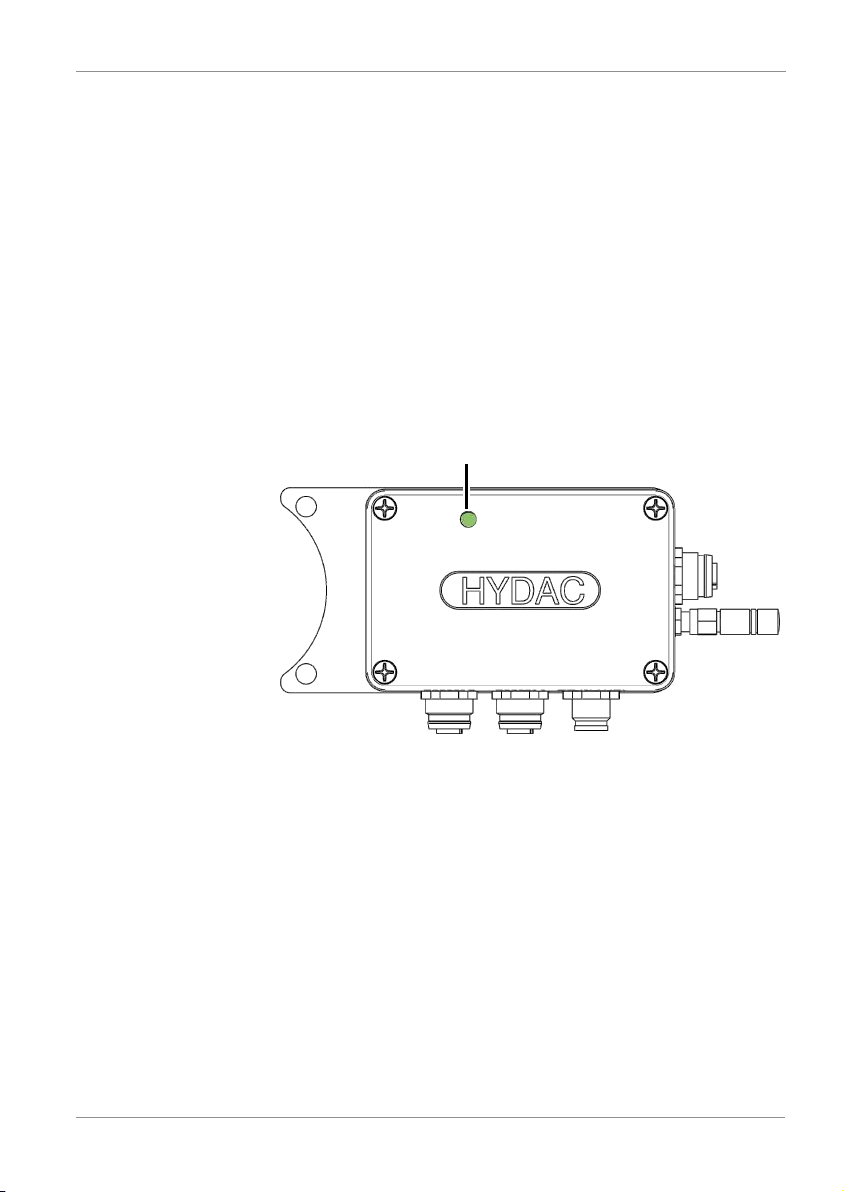
Status LED
7 Operation
For operation, switch the voltage supply to the CSI on or plug
the power supply unit into a suitable socket.
During operation, note the status LED on the CSI.
– If the status LED is not lit, the CSI is not being supplied
with power.
– If the status LED is orange, the CSI is still booting up.
– If the status LED is green, the CSI is functioning normally.
– If the status LED is red, there is a fault. Details regarding
this can be found in the chapter Troubleshooting/fault rec-
tification [}49]
Fig.15:
Status LED
Bewa CSI-C-11 4191469a en-us lq 39 / 64
Page 40
7 | Operation HYDAC FILTER SYSTEMS GMBH
7.1 Evaluating/reading measurement protocols/values
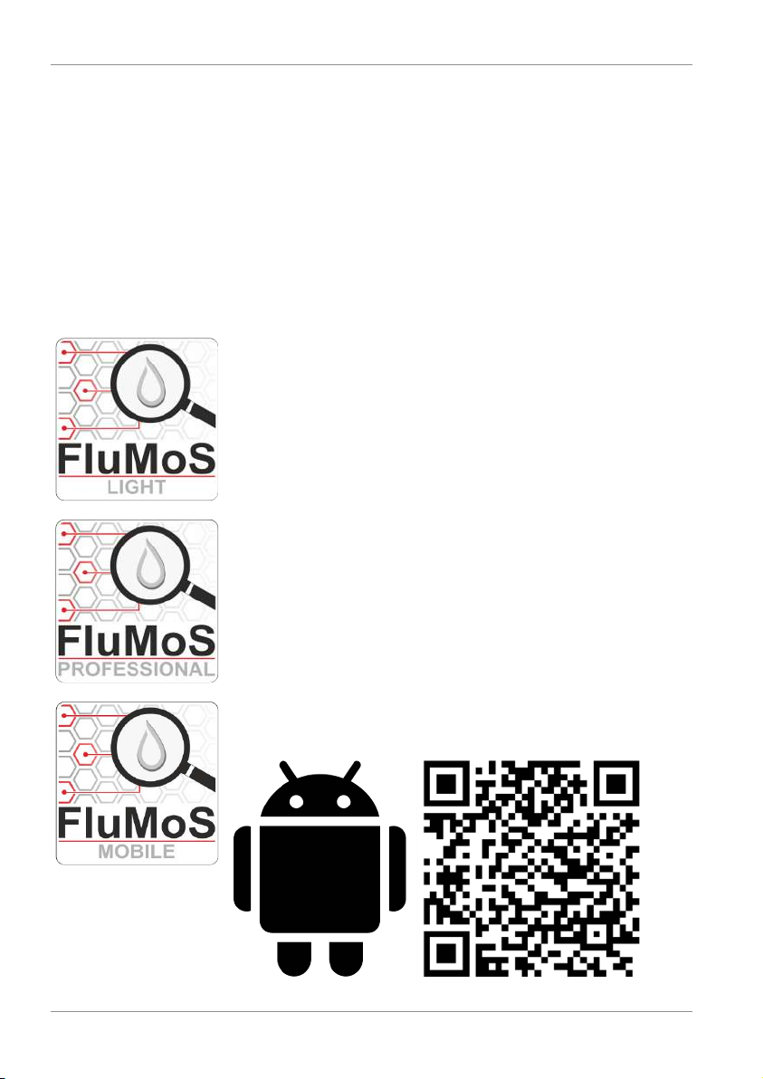
In order to read/evaluate measurement protocols, you can select one of the following software/protocols.
7.1.1 Evaluating/reading measurement reports/values with FluMoS
The FluidMonitoringsoftware FluMoS is meant for reading and
analyzing measurement protocols/measured values from
HYDAC sensors/interfaces or devices.
FluMoS light is available as a download from the homepage at
www.hydac.com.
You can order FluMoS professional as an accessory for a fee.
You can get FluMoS mobile for your Android mobile device on
the Google Play Store.
40 / 64 Bewa CSI-C-11 4191469a en-us lq
Page 41

HYDAC FILTER SYSTEMS GMBH Operation | 7
7.1.2 Reading measurement protocols/values via Modbus
Through the Ethernet or RS485 interface with an implemented
Modbus® protocol, you can integrate the connected sensors
into a network or the higher-level ConditionMonitoringSystem
CMS or the control systems (PLC) and process control systems.
Here, the measurement protocols or measured data are made
available via Ethernet (Modbus® TCP) or RS485 (Modbus
RTU). The input registers described in the following are applicable to the TCP as well as the RTU models.
Modbus® function "Read Input Register" - (function code
0x04)
Using the Modbus® function, the "Read Input Register" reads
one or more registers and sends the data back. Per register,
two bytes will be sent (high byte first). For that, you can set two
different formats for the registers, "New format" or "Old format".
For details, see factory settings.
®
Bewa CSI-C-11 4191469a en-us lq 41 / 64
Page 42

7 | Operation HYDAC FILTER SYSTEMS GMBH
7.1.2.1 Mapping - new format
Here, you will find the mapping for the Modbus - new format.
CSI-C-11 Input registers
Device ID (16 characters)
8 registers with 2
characters each
Status code 0x0008 + Register Offset
Error code 0x0009 + Register Offset
Channel 1 (32bit) 0x000A + Register offset high byte
Channel 2 (32bit) 0x000C + Register offset high byte
Channel 3 (32bit) 0x000E + Register offset high byte
Channel 4 (32bit) 0x0010 + Register offset high byte
Channel 5 (32bit) 0x0012 + Register offset high byte
Channel 6 (32bit) 0x0014 + Register offset high byte
Channel 7 (32bit) 0x0016 + Register offset high byte
Channel 8 (32bit) 0x0018 + Register offset high byte
Channel 9 (32bit) 0x001A + Register offset high byte
0x0000 + Register Offset
0x0001 + Register Offset
0x0002 + Register Offset
0x0003 + Register Offset
0x0004 + Register Offset
0x0005 + Register Offset
0x0006 + Register Offset
0x0007 + Register Offset
0x000B + Register offset low byte
0x000D + Register offset low byte
0x000F + Register offset low byte
0x0011 + Register offset low byte
0x0013+ Register offset low byte
0x0015 + Register offset low byte
0x0017 + Register offset low byte
0x0019 + Register offset low byte
0x001B + Register offset low byte
42 / 64 Bewa CSI-C-11 4191469a en-us lq
Page 43

HYDAC FILTER SYSTEMS GMBH Operation | 7
CSI-C-11 Input registers
… … …
… …
Channel 24 (32bit) 0x0038 + Register offset high byte
0x0039 + Register offset low byte
Tab.18:
Mapping - new format
The register offset can be parametrized in the dialog menu
(factory setting: 0x0000).
Bewa CSI-C-11 4191469a en-us lq 43 / 64
Page 44

7 | Operation HYDAC FILTER SYSTEMS GMBH
See also
2 Factory settings [}35]
7.1.2.2 Mapping -old format
Here, you will find the mapping of the Modbus - old format.
Input registers
Sensor 1 Input registers
Device ID (16 characters) 8 registers
with 2 characters
each
Status code 0x1000
Error code 0x1001
Channel 1 (32bit) 0x2000 high byte
… … …
Channel 32 (32bit) 0x203E high byte
… … …
Sensor 2 + analog
module
Device ID (16 characters) 8 registers
with 2 characters
each
0x0000
0x0001
0x0002
0x0003
0x0004
0x0005
0x0006
0x0007
0x2001 low byte
… …
0x203F low byte
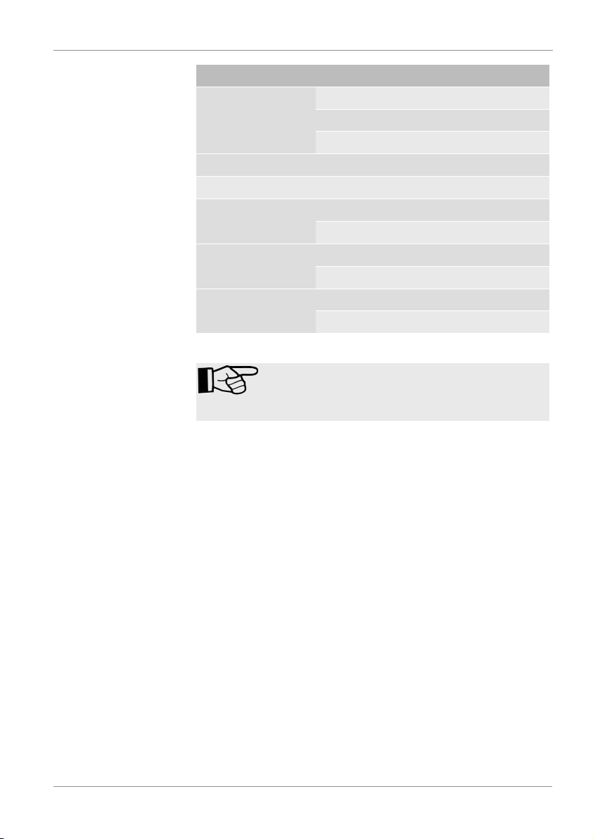
Input register (offset
0x8000)
0x8000
0x8001
0x8002
0x8003
0x8004
44 / 64 Bewa CSI-C-11 4191469a en-us lq
Page 45
HYDAC FILTER SYSTEMS GMBH Operation | 7
Input registers
0x8005
0x8006
0x8007
Status code 0x9000
Error code 0x9001
Channel 1 (32bit) 0xA000 high byte
0xA001 low byte
… … …
… …
Channel 32 (32bit) 0xA03E high byte
0xA03F low byte
Tab.19:
Mapping – old format
The allocation of the input register can be called
up in the dialog menu. It depends on the sensors
actually connected.
Bewa CSI-C-11 4191469a en-us lq 45 / 64
Page 46
7 | Operation HYDAC FILTER SYSTEMS GMBH
See also
2 Factory settings [}35]
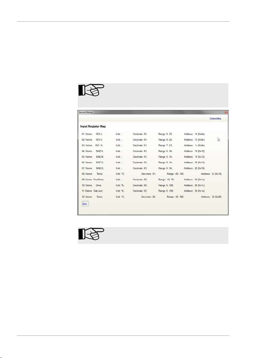
7.1.2.3 Example with CS1000 / AS1000
The following is an example with the CS1000 and AS1000.
The allocation of the input register can be called
up in the dialog menu. It depends on the sensors
actually connected.
Fig.16:
Example: sensor dialog
Sensor 1 + sensor 2 must have different bus addresses.
46 / 64 Bewa CSI-C-11 4191469a en-us lq
Page 47

HYDAC FILTER SYSTEMS GMBH Operation | 7
7.1.3 Reading measurement protocols/values via FluMoT
The FluidMonitoring Toolkit FluMoT is a package of drivers
and programs that helps you to connect HYDAC sensors to
your own user environment/software.
For this purpose you have access to all HYDAC program libraries, a detailed description and help, and example programs in various software languages.
Bewa CSI-C-11 4191469a en-us lq 47 / 64
Page 48

8 | Maintenance HYDAC FILTER SYSTEMS GMBH
8 Maintenance
The ContaminationSensorInterface CSI is maintenance-free.
48 / 64 Bewa CSI-C-11 4191469a en-us lq
Page 49

HYDAC FILTER SYSTEMS GMBH Troubleshooting/fault rectification | 9
9 Troubleshooting/fault rectification
The following errors can occur during operation of the CSI.
LED High
Byte
Low
Byte
Description Rectification
- - - The CSI is not being supplied with
power.
Green 0 0 No error. -
Orange
0 0 Booting phase, the
CSI does not answer during this
time.
Red 0 1 Error in communi-
cation with sensor
1.
Red 0 2 Error in communi-
cation with sensor
2
Red 0 3 Error in initializing
the analog module.
Red 0 4 Error in initializing
the WIFI module.
Red 0 5 Initializing the CSI -
Red 0 6 Error in the flash
memory.
Red 0 16 Error in loading the
user settings.
Switch on the
power supply to
the CSI.
Wait until the LED
lights up green or
red.
Check SMART
Sensor Count in
Device Settings,
restart CSI, check
sensor 1, check
cabling
Check
SMARTSensor
Count in Device
Settings, restart
CSI, check sensor
2, check cabling
Restart the CSI.
Restart the CSI.
Delete the log
memory and
restart the CSI.
Restart the CSI.
Bewa CSI-C-11 4191469a en-us lq 49 / 64
Page 50
9 | Troubleshooting/fault rectification HYDAC FILTER SYSTEMS GMBH
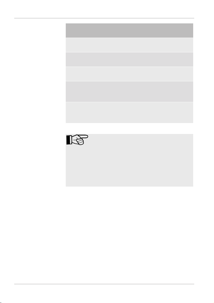
LED High
Byte
Low
Byte
Description Rectification
Red 0 17 Error in saving the
user settings.
Red 0 18 Error in loading the
factory settings.
Red 0 19 Error in saving the
factory settings.
Red 1 X x = Error code from
sensor 1.
Red 2 y y = Error code from
sensor 2.
Tab.20:
Troubleshooting
If a connection is not possible via WLAN/WiFi to
the CSI, check the following points:
- Reception is disrupted by environmental factors, e.g. the antenna being covered.
- The distance to the CSI is too large.
The PC or smartphone/tablet is connected with a
different access point in WLAN.
Restart the CSI.
Restart the CSI.
Restart the CSI.
Read the details
in the documentation for sensor 1.
Read the details
in the documentation on sensor 2.
50 / 64 Bewa CSI-C-11 4191469a en-us lq
Page 51

HYDAC FILTER SYSTEMS GMBH Removing / Disposal | 10
10 Removing / Disposal
– Dismount the product completely, including all of its com-
ponents, before decommissioning. Disconnect or remove
the electrical connection.
– Dispose of the packaging material in an environmentally
friendly manner.
– After dismantling the product and separating its various
materials into categories, dispose of all parts in an environmentally friendly manner.
Bewa CSI-C-11 4191469a en-us lq 51 / 64
Page 52
11 | Appendix HYDAC FILTER SYSTEMS GMBH
11 Appendix
In this annex, you will find supplementary information on the
product.
11.1 Accessories
For optimum system integration of the HYDAC
ConditionSensorInterface CSI-C-11, the following original accessories are available:
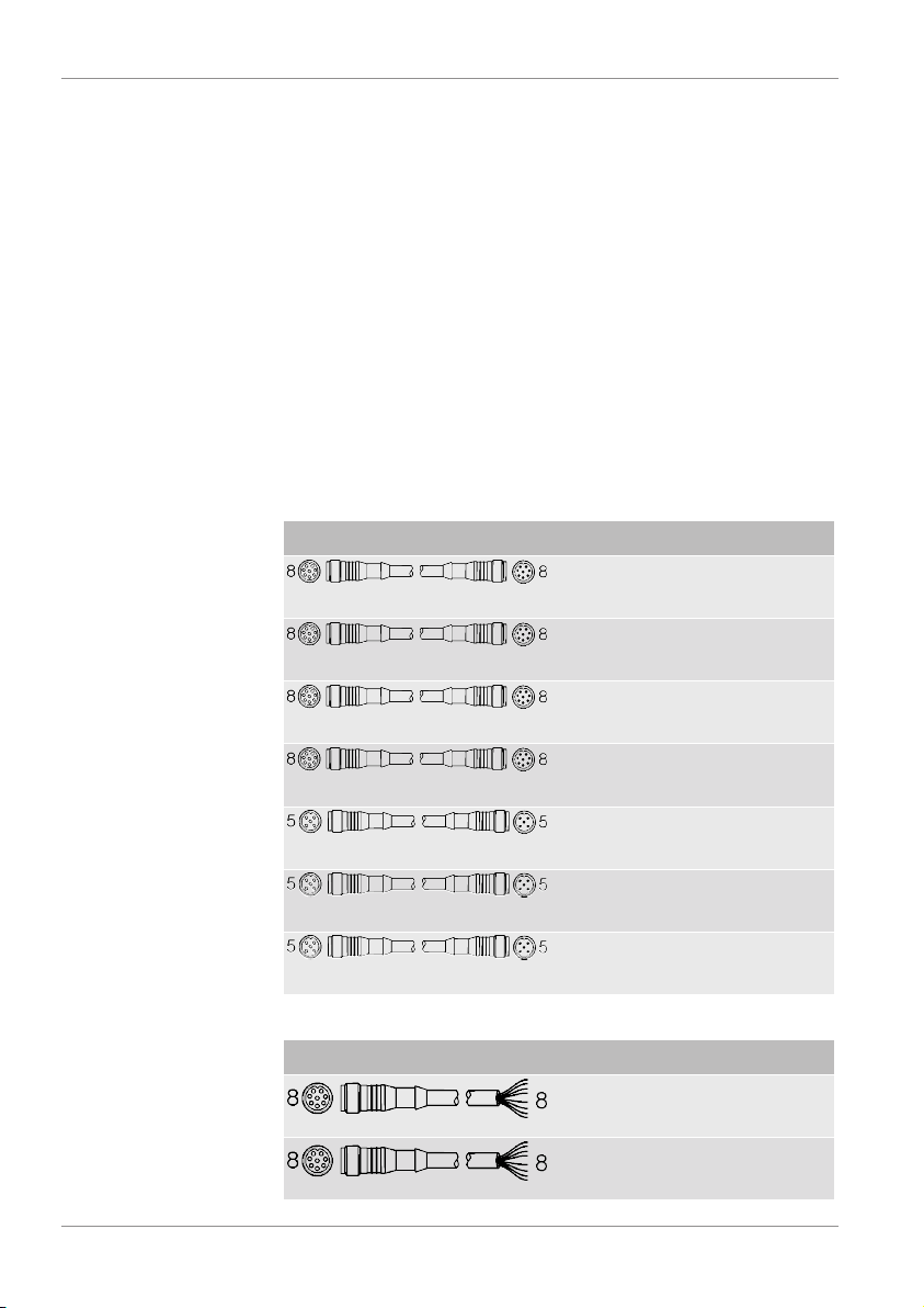
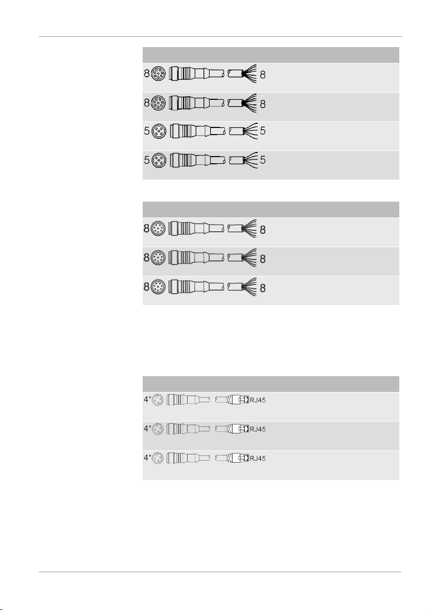
Connection cables
The following connection cables for the sensors are available:
Socket <-> plug/open end Length Part no.
10 m ZBE43-103519768
0.5 m ZBE43-
4193544
005
5 m ZBE43-053281240
10 m ZBE43-103519768
0.5 m ZBE30-
4193586
005
5 m ZBE30-056040852
10 m ZBE30-103729098
Tab.21:
Connection cable - socket <-> plug
Socket <-> open end Length Part no.
2 m ZBE42S
3281220
-02
5 m ZBE42S
3281239
-05
52 / 64 Bewa CSI-C-11 4191469a en-us lq
Page 53
HYDAC FILTER SYSTEMS GMBH Appendix | 11
Socket <-> open end Length Part no.
10 m ZBE42S
3449681
-10
20 m ZBE42S
3654932
-20
5 m ZBE47S
3527626
-05
10 m ZBE47S
3527627
-10
Tab.22:
Connection cable – socket <-> open end
Plug <-> open end Length Part no.
2 m ZBE48S
6072261
-02
5 m ZBE48S
6070712
-05
10 m ZBE48S
6072262
-10
Tab.23:
Connection cable – plug <-> open end
Connecting cable – Ethernet
The following connection cables for Ethernet are available:
Length Part no.
5 m ZBE45-053281240
10 m ZBE45-103519768
30 m ZBE45-304217234
Tab.24:
Connection cable - sensors
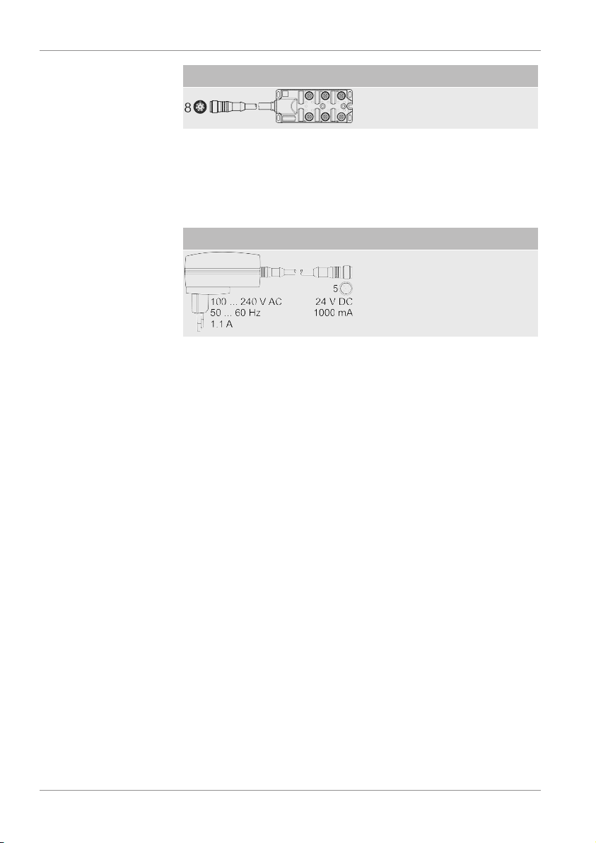
Connection adapters
The following connection adapters for connecting analog sensors and signals are available:
Bewa CSI-C-11 4191469a en-us lq 53 / 64
Page 54
11 | Appendix HYDAC FILTER SYSTEMS GMBH
Length Part no.
1 m ZBECSI
4420372
-60
Tab.25:
Connection adapters
Power supply unit
The following power supply units are available:
Length Part no.
1.8 m PS5 3399939
Tab.26:
Power supply unit
54 / 64 Bewa CSI-C-11 4191469a en-us lq
Page 55

HYDAC FILTER SYSTEMS GMBH Table of Illustrations
Table of Illustrations
Fig. 1 Overview / labeling of the title page .........................................................
Fig. 2 CSI-C-11 dimensions ...............................................................................
Fig. 3 Type label.................................................................................................
Fig. 4 Model code CSI-C-11...............................................................................
Fig. 5 Assembling the CSI-C-11.........................................................................
Fig. 6 Example: CSI-C-11 assembled on a CSM-E ...........................................
Fig. 7 Example: CSI-C-11 assembled on a motor-pump assembly ...................
Fig. 8 Connection overview ................................................................................
Fig. 9 DC IN / HSI...............................................................................................
Fig. 10 Sensor 1 IN ..............................................................................................
Fig. 11 Sensor 2 IN ..............................................................................................
Fig. 12 LAN...........................................................................................................
Fig. 13 Connection example CSI-C-11-0-0-0 .......................................................
Fig. 14 Connection example CSI-C-11 - CS1000 - HDA48x6-A - ETS7246-B ....
Fig. 15 Status LED ...............................................................................................
7
19
24
25
27
28
28
29
30
30
31
31
32
33
39
Fig. 16 Example: sensor dialog ............................................................................
Bewa CSI-C-11 4191469a en-us lq 55 / 64
46
Page 56

Index of Tables HYDAC FILTER SYSTEMS GMBH
Index of Tables
Tab. 1 Impressum................................................................................................
Tab. 2 Documentation Representative ................................................................
Tab. 3 Target group.............................................................................................
Tab. 4 Required qualifications/training ................................................................
Tab. 5 Scope of delivery......................................................................................
Tab. 6 Input data .................................................................................................
Tab. 7 Outputs.....................................................................................................
Tab. 8 Electrical data...........................................................................................
Tab. 9 Internal measurement data memory ........................................................
Tab. 10 Other data ................................................................................................
Tab. 11 Decoding the model code label ................................................................
Tab. 12 Pin assignment – DC IN / HSI ..................................................................
Tab. 13 Pin assignment – Sensor 1 IN ..................................................................
Tab. 14 Pin assignment – Sensor 2 IN ..................................................................
Tab. 15 Pin assignment - LAN...............................................................................
4
4
5
6
18
22
22
22
23
23
24
30
30
31
31
Tab. 16 Description of the factory settings ............................................................
Tab. 17 Factory settings of CSI-C-11-0-0-1/-000 ..................................................
Tab. 18 Mapping - new format...............................................................................
Tab. 19 Mapping – old format................................................................................
Tab. 20 Troubleshooting........................................................................................
Tab. 21 Connection cable - socket <-> plug..........................................................
Tab. 22 Connection cable – socket <-> open end .................................................
Tab. 23 Connection cable – plug <-> open end.....................................................
Tab. 24 Connection cable - sensors......................................................................
56 / 64 Bewa CSI-C-11 4191469a en-us lq
35
37
42
44
49
52
52
53
53
Page 57

HYDAC FILTER SYSTEMS GMBH Index of Tables
Tab. 25 Connection adapters ................................................................................
Tab. 26 Power supply unit .....................................................................................
54
54
Bewa CSI-C-11 4191469a en-us lq 57 / 64
Page 58
Glossary HYDAC FILTER SYSTEMS GMBH
Glossary
DIN
Abbreviation for Deutsches Institut
für Normung.
FluMoS mobile
General Terms and Conditions
The General Terms and Conditions
are available at our home page
www.hydac.com -> General Terms
and Conditions.
WIFI
Abbreviation for "wireless fidelity".
Is also a synonym for W-LAN.
WLAN
You can get FluMoS mobile for your
mobile end device on Android oper-
ating system on the Google Play
Store.
58 / 64 Bewa CSI-C-11 4191469a en-us lq
Page 59

HYDAC FILTER SYSTEMS GMBH Glossary
Is the abbreviation for Wireless LAN
(Local Area Network). Also a syn-
onym for WiFi.
Bewa CSI-C-11 4191469a en-us lq 59 / 64
Page 60

Index HYDAC FILTER SYSTEMS GMBH
Index
D
decommissioning 51
disposal 51
E
exclusion of liability 13
I
Imprint 4
M
manufacturer 4
P
Person authorized with the documenta-
tion 4
T
Terms and Conditions 13
Terms of Delivery 13
W
Warranty 13
60 / 64 Bewa CSI-C-11 4191469a en-us lq
Page 61

Page 62

Page 63

Page 64

 Loading...