

Page 1
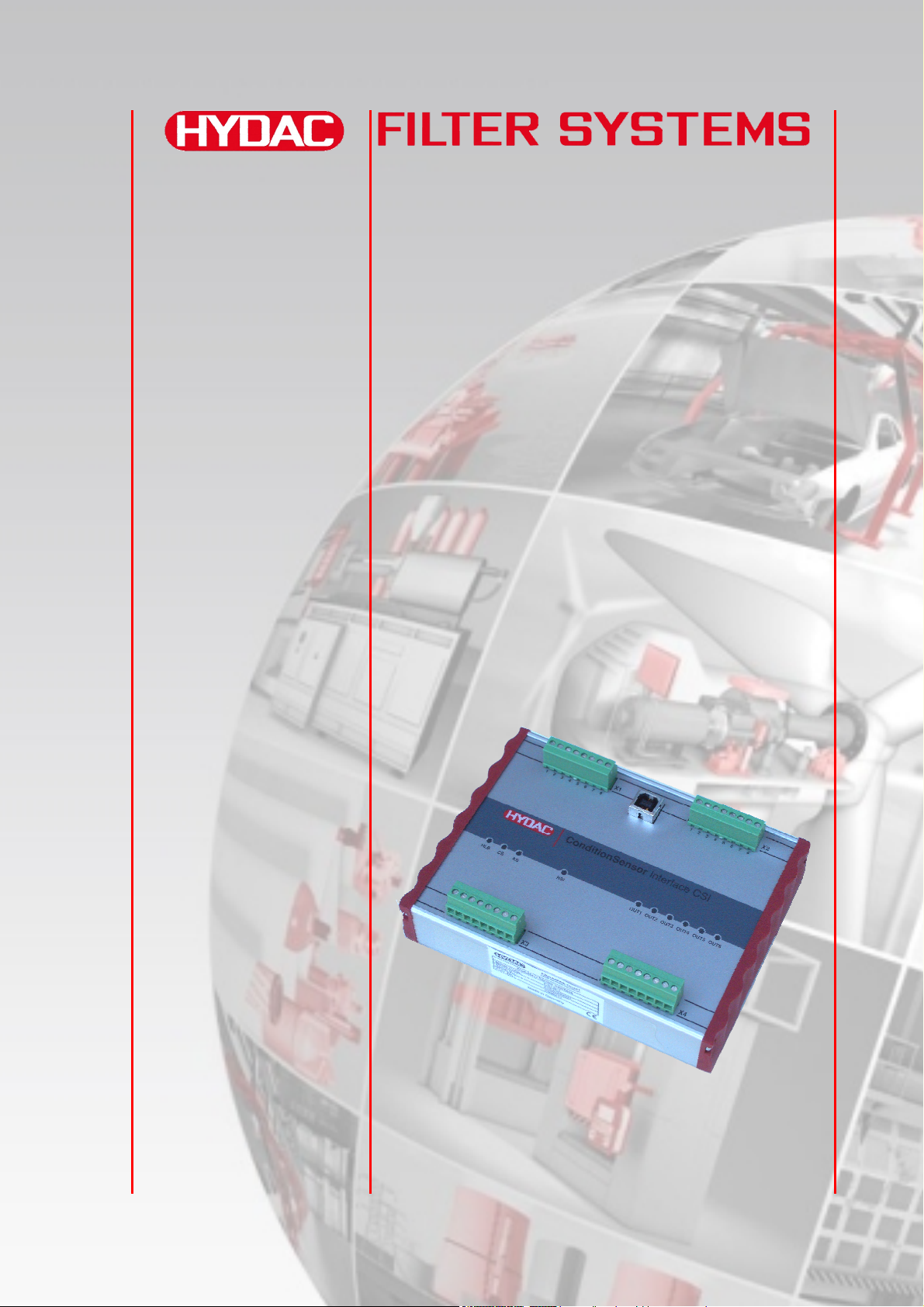
CSI-B-1
ConditionSensor Interface
Operating Instruction
English (translation of original instructions)
Valid from firmware versions V 1.11 up
Documentation no.: 3424452b
Page 2

CSI-B-1 Imprint
Imprint
Publisher and responsible for the content:
HYDAC FILTER SYSTEMS GMBH
Postfach 1251
66273 Sulzbach / Saarland
Germany
Telephone: +49 (0)6897 509 01
Fax: +49 (0)6897 509 846
E-mail:
Homepage: www.hydac.com
Court of Registration: Saarbrücken, HRB 17216
Executive director: Mathias Dieter,
Dipl.Kfm. Wolfgang Haering
Documentation Representative
Mr. Günter Harge
c/o HYDAC International GmbH, Industriegebiet, 66280 Sulzbach / Saar
Telephone: ++49 (0)6897 509 1511
Telefax:
E-mail:
++49 (0)6897 509 1394
© HYDAC FILTER SYSTEMS GMBH
All rights reserved. No part of this work may be reproduced in any form (print,
photocopy or by other means) or processed, duplicated or distributed using
electronic systems without the written consent of the publisher.
These documents have been created and inspected with the greatest care.
However, errors cannot be ruled out completely.
All details are subject to technical modifications. Technical specifications are subject
to change without notice.
The trademarks of other companies are exclusively used for the products of those
companies.
HYDAC FILTER SYSTEMS GMBH
BeWa CSI-B-1 3424452b 2012-04-20 en-us.doc 2012-04-20
en(us)
Page 2 / 36
Page 3

CSI-B-1 Contents
Contents
Imprint .......................................................................................................................2
Documentation Representative...............................................................................2
Contents....................................................................................................................3
Preface ......................................................................................................................5
Technical Support...................................................................................................6
Modifications to the Product ...................................................................................6
Warranty .................................................................................................................6
Using the Documentation .......................................................................................7
General ...................................................................................................................... 8
Using this Manual ...................................................................................................8
Explanation of Symbols and Warnings ................................................................... 8
Checking the Scope of Delivery.............................................................................. 9
CSI-B-1 Features ....................................................................................................10
System Requirements............................................................................................ 11
System requirements for hardware....................................................................... 11
Software................................................................................................................ 11
Observe before connecting................................................................................... 11
Assembling the CSI-B-1......................................................................................... 11
Installing USB Driver(s) .........................................................................................12
CSI-B-1 Connection Overview...............................................................................13
Checking CS1000 hardware index .......................................................................14
Connecting CS1000 with Hardware Index "a" or "b"............................................. 15
Connecting CS1000 with hardware index "c" or later ........................................... 15
Connecting AS1000..............................................................................................16
Connecting HLB1000............................................................................................ 16
Setting up Connection with PC ............................................................................. 17
Connecting the Voltage Supply ............................................................................17
CSI-B-1 is detected by the PC ............................................................................... 18
Parameterizing CSI-B-1 with the HyperTerminal.................................................19
Checking/setting interface parameters ................................................................. 20
Parameter Mode .....................................................................................................23
HSI Transparent Mode ...........................................................................................24
Configuring Analog Output ................................................................................... 25
Configuring Switching Output R1 / R2 / R3 / R4 .................................................. 25
CS 1000 - Reading out measured values .............................................................26
HYDACLab - Reading out measured values ........................................................28
AS 1000 - Reading out measured values .............................................................29
Accessories ............................................................................................................30
Plugs.....................................................................................................................30
Connection Cable, Shielded .................................................................................30
Cable Coding ........................................................................................................ 31
HYDAC FILTER SYSTEMS GMBH
BeWa CSI-B-1 3424452b 2012-04-20 en-us.doc 2012-04-20
en(us)
Page 3 / 36
Page 4

CSI-B-1 Contents
Power Supply Unit for CS1000 ............................................................................. 31
Disposing of the CSI-B-1 .......................................................................................32
Model Code ............................................................................................................. 32
Technical Data ........................................................................................................ 33
HYDAC FILTER SYSTEMS GMBH
BeWa CSI-B-1 3424452b 2012-04-20 en-us.doc 2012-04-20
en(us)
Page 4 / 36
Page 5

CSI-B-1 Preface
Preface
For you, as the owner of a product manufactured by us, we have produced this
manual, comprising the most important instructions for its operation and
maintenance.
It is intended to help you become acquainted with the ins and outs of the product
and use it properly.
You should keep it in the vicinity of the product so it is always at your fingertips.
Sometimes the information contained in the documentation cannot always keep up
with changes made to the product as we attach considerable importance to keeping
our products cutting-edge. Consequently, there might be deviations in technical
details, illustrations and dimensions.
If you discover errors while reading the documentation or have suggestions or other
useful information, please don’t hesitate to contact us:
HYDAC FILTER SYSTEMS GMBH
Technische Dokumentation
Postfach 12 51
66273 Sulzbach / Saar
Germany
We look forward to receiving your input.
Our motto: “Putting experience into practice”
HYDAC FILTER SYSTEMS GMBH
BeWa CSI-B-1 3424452b 2012-04-20 en-us.doc 2012-04-20
en(us)
Page 5 / 36
Page 6

CSI-B-1 Preface
Technical Support
If you have any questions, suggestions, or encounter any problems of a technical
nature, please don't hesitate to contact us. When contacting us, please always
include the model/type designation and article no. of the product:
Fax: +49 (0) 6897 / 509 - 846
E-mail:
Modifications to the Product
We would like to point out that changes to the product (e.g. purchasing options, etc.)
may result in the information in the operating instructions no longer being completely
accurate or sufficient.
When making modifications or performing repair work to components affecting the
safety of the product, the product may not be put back into operation until it has
been examined and released by a HYDAC representative.
Please notify us immediately of any modifications made to the product whether by
you or a third party.
Warranty
For the warranty provided by us, please refer to the General Terms of Sale and
Delivery of HYDAC FILTER SYSTEMS GmbH.
You will find these under www.hydac.com -> General terms and conditions.
HYDAC FILTER SYSTEMS GMBH
BeWa CSI-B-1 3424452b 2012-04-20 en-us.doc 2012-04-20
en(us)
Page 6 / 36
Page 7
CSI-B-1 Preface
Using the Documentation
Please note that the method described above of locating specific
information does not release you from your responsibility for carefully
reading the entire manual prior to starting the unit up for the first time
and carefully rereading the manual at regular intervals later on.
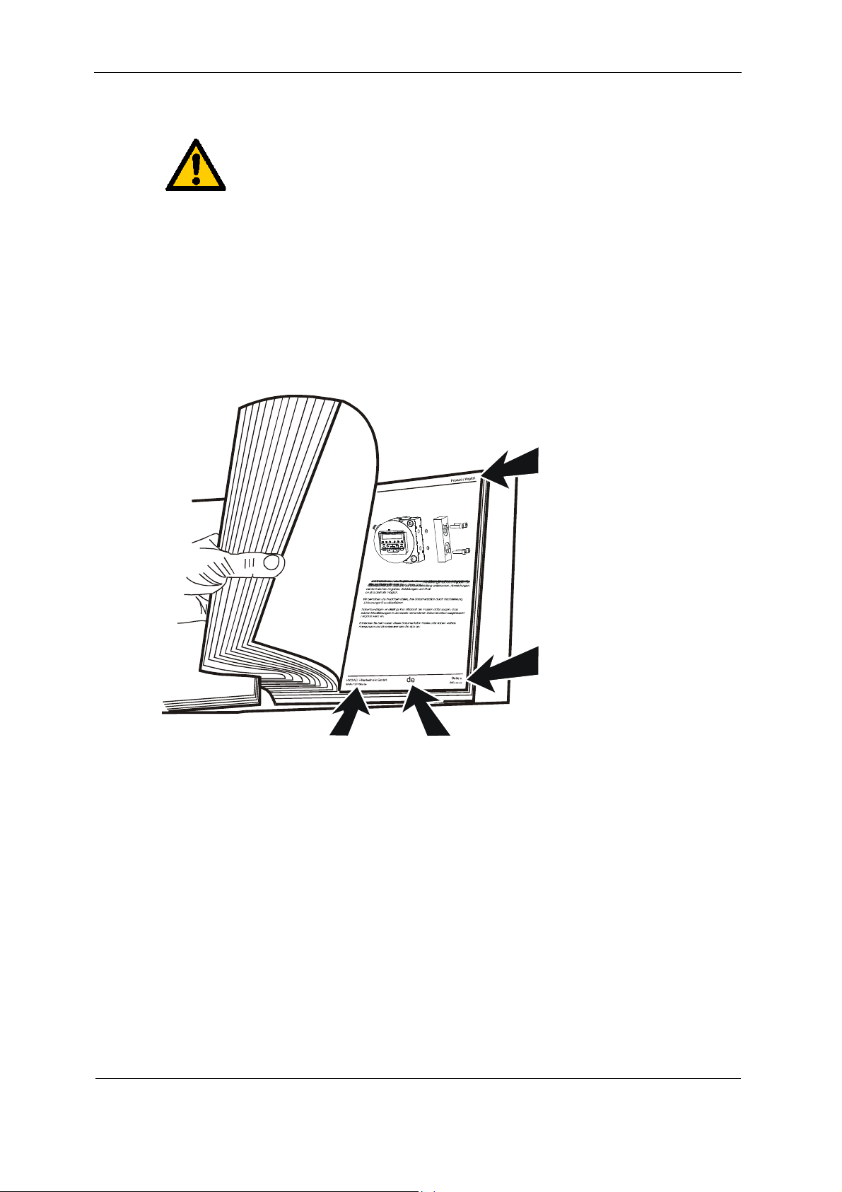
WHAT do you want to know?
I determine which topic I am looking for.
WHERE can I find the information I’m looking for?
The document has a table of contents at the beginning. I select the chapter I'm
looking for and the corresponding page number.
Product description /
Chapter heading
Page number
Edition date
Documentation No.
with Index /
File name
Document language
The documentation number with its index enables you to order another copy of the
operating an
d maintenance instructions. The index is incremented every time the
manual is revised or changed.
HYDAC FILTER SYSTEMS GMBH
BeWa CSI-B-1 3424452b 2012-04-20 en-us.doc 2012-04-20
en(us)
Page 7 / 36
Page 8
CSI-B-1 General
General
With the ConditionSensor Interface (henceforth only referred to as CSI), the
following devices can be conveniently monitored:
ContaminationSensor CS1000
AquaSensor AS1000
HYDACLab HLB1000
The CSI-B-1 can read out only a maximum of 1 sensor!
Using this Manual
In order to keep the instructions simple, the software is explained using examples
with the CS1000 sensor. These explanations naturally also apply analogously to the
AS1000, HYDACLab (HLB1000).
In this manual, we assume that the user has a working knowledge of
Windows, as well as how Windows programs are structured and installed.
Explanation of Symbols and Warnings
The following designations and symbols are used in this manual:
Important information is summarized under this symbol.
This symbol designates tips for use and other particularly useful
information.
This symbol provides important tips for the proper handling and
operation of the product. The non-observance of these instructions
can lead to false use or malfunction of the product.
For any questions or queries regarding FluMoS light, please contact our technical
sales department.
HYDAC FILTER SYSTEMS GMBH
Postfach 12 51
66273 Sulzbach / Saar
Germany
E-mail:
Fax: +49 (0) 6897 509 846
HYDAC FILTER SYSTEMS GMBH
BeWa CSI-B-1 3424452b 2012-04-20 en-us.doc 2012-04-20
en(us)
Page 8 / 36
Page 9
CSI-B-1 Checking the Scope of Delivery
Checking the Scope of Delivery
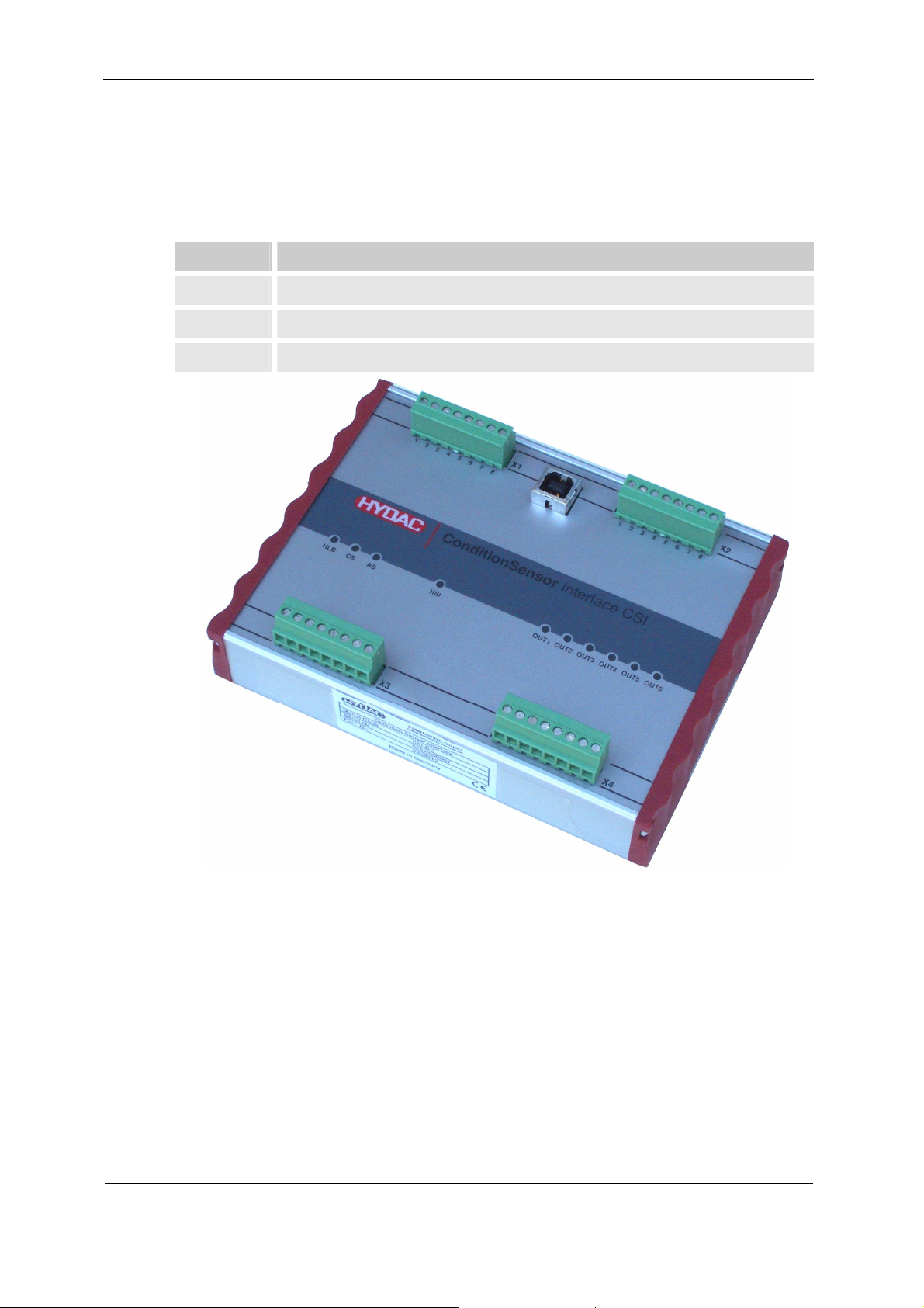
The ConditionSensor Interface comes packed and factory-assembled. Before
starting up the CSI-B-1, check that the content of the package is complete.
The following items are supplied:
Qty Description
1 ConditionSensor Interface CSI-B-1
1 Support CD with USB driver software and Operating Instruction
1 Operating Instruction (this document)
HYDAC FILTER SYSTEMS GMBH
BeWa CSI-B-1 3424452b 2012-04-20 en-us.doc 2012-04-20
en(us)
Page 9 / 36
Page 10

CSI-B-1 CSI-B-1 Features
CSI-B-1 Features
The condition sensor interface CSI-B-1 makes it possible to easily integrate the
following sensors into analog data acquisition systems:
- ContaminationSensor CS1000,
- AquaSensor AS1000,
- HYADCLab HLB1000.
These sensors determine two or four measured values which can be extracted via a
digital interface or an analog output.
In the case of analog output, the two or four measured values are either transferred
chronologically one after the other or the output is permanently set to a single
measurement channel.
In view of the fact that the data collection systems which are used often do not
enable any simple decoding of the chronologically coded analog signal, the CSI-B-1
is made available as an easy-to-use module which outputs the sensor data in the
form of four separate analog signals.
The connected sensor is recognized automatically – no configuration of the CSI-B-1
is required.
In addition, the module can be utilized as a miniature monitoring system. A readily
programmable switching output is available for each of the four measurement
channels which can be used to monitor whether a measurement parameter is within
or outside of a range or whether limit values are exceeded or not achieved.
The ConditionSensor Interface CSI-1-B can be parameterized through the USB
interface via hyperterminal.
HYDAC FILTER SYSTEMS GMBH
BeWa CSI-B-1 3424452b 2012-04-20 en-us.doc 2012-04-20
en(us)
Page 10 / 36
Page 11
CSI-B-1 System Requirements
System Requirements
System requirements for hardware
Pentium processor 200 MHz or higher
64 MB RAM memory
Microsoft Internet Explorer 4.0 or higher
VGA graphic card (800x600 min.)
Hard disk with a minimum of 15 MB free disk space
A free USB port that is not being used by any other program (e.g. terminal,
modem or network software)
Microsoft Windows-compatible mouse
Software
Operating system: WINDOWS 2000, XP,
WINDOWS 7 only with installed HyperTerminal
Administrator rights to software installation
Observe before connecting
Uninstall older versions of the USB driver from your PC to ensure that the software
functions properly.
Read the Operating Instruction all the way through.
Assembling the CSI-B-1
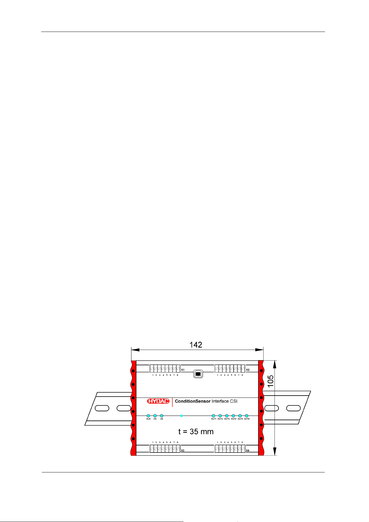
The CSI-B-1 is intended for installation on size 35 top hat rails in accordance with
EN 60715. The CSI-B-1 has a corresponding fastening profile on its rear side for this
purpose.
(Dimension t = component height. All dimensions in mm)
HYDAC FILTER SYSTEMS GMBH
BeWa CSI-B-1 3424452b 2012-04-20 en-us.doc 2012-04-20
en(us)
Page 11 / 36
Page 12
CSI-B-1 Installing USB Driver(s)
Installing USB Driver(s)
Before connecting the CSI-B-1 to the PC, install the USB driver from the support CD
as described below.
Note that the USB driver provided is software which is subject to the conditions
outlined in our "Special Sales and Delivery Conditions for Software Products and
Freeware", with which your are already familiar.
These can be found on our homepage under:
www.hydac.com
=> General Terms and Conditions
With the installation of the software, you declare your consent to the "Special Sales
and Delivery Conditions for Software Products and Freeware".
Administrator rights for the PC on which the USB driver is to be installed are
required for such installation.
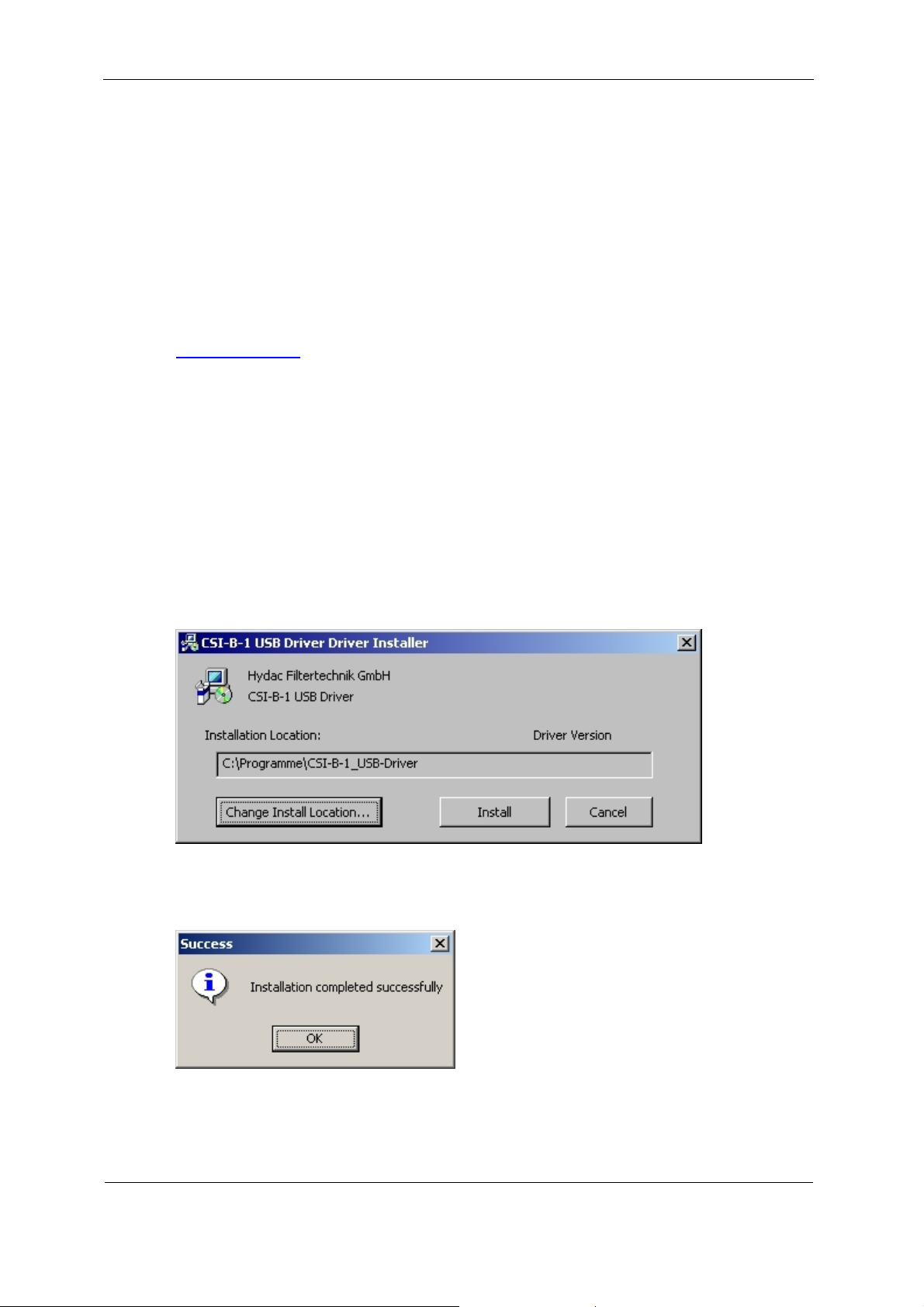
Double-click to start the file "CP210xVCPInstaller.exe", which is found on the
Support CD in the CSI-B-1 USB driver directory.
You will receive the following message if the installation has been successfully
completed:
Restart the PC.
HYDAC FILTER SYSTEMS GMBH
BeWa CSI-B-1 3424452b 2012-04-20 en-us.doc 2012-04-20
en(us)
Page 12 / 36
Page 13
CSI-B-1 CSI-B-1 Connection Overview
CSI-B-1 Connection Overview
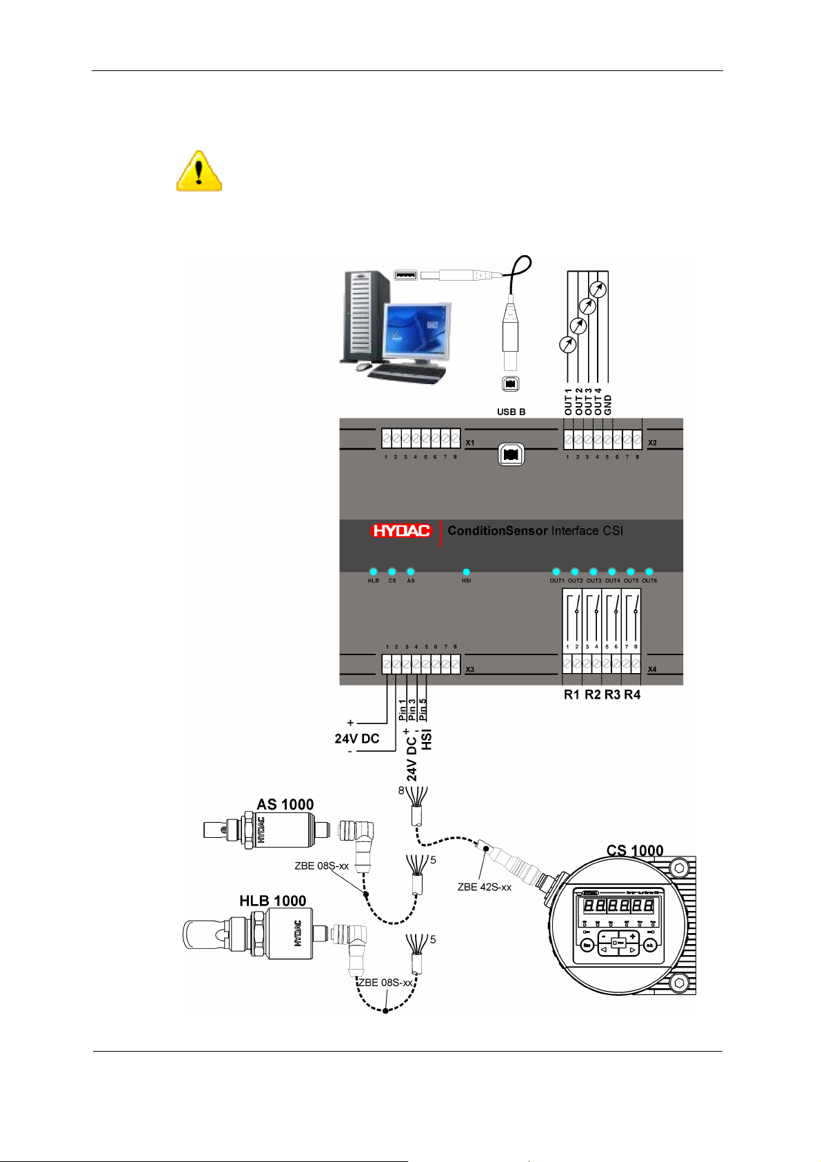
The maximum line length from CSI to the sensor is 10 m.
Connect the CSI-B-1 as described below:
HYDAC FILTER SYSTEMS GMBH
BeWa CSI-B-1 3424452b 2012-04-20 en-us.doc 2012-04-20
en(us)
Page 13 / 36
Page 14
CSI-B-1 CSI-B-1 Connection Overview
x
x
Checking CS1000 hardware index
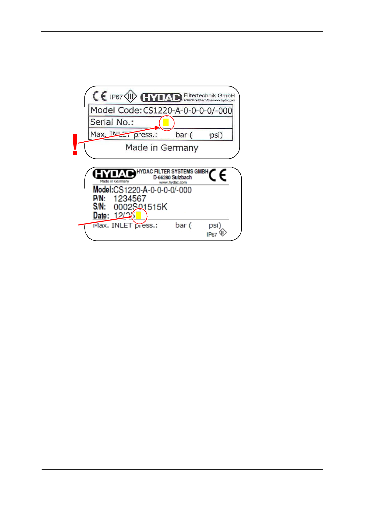
For identification details of the CS1000, see the type label. This is located in a very
visible spot on the upper side of the device and includes the hardware index in the
serial number.
C
6 00083230
xxx
1234567
E
xx
!
xxxx
xxx
HYDAC FILTER SYSTEMS GMBH
BeWa CSI-B-1 3424452b 2012-04-20 en-us.doc 2012-04-20
en(us)
Page 14 / 36
Page 15
CSI-B-1 CSI-B-1 Connection Overview
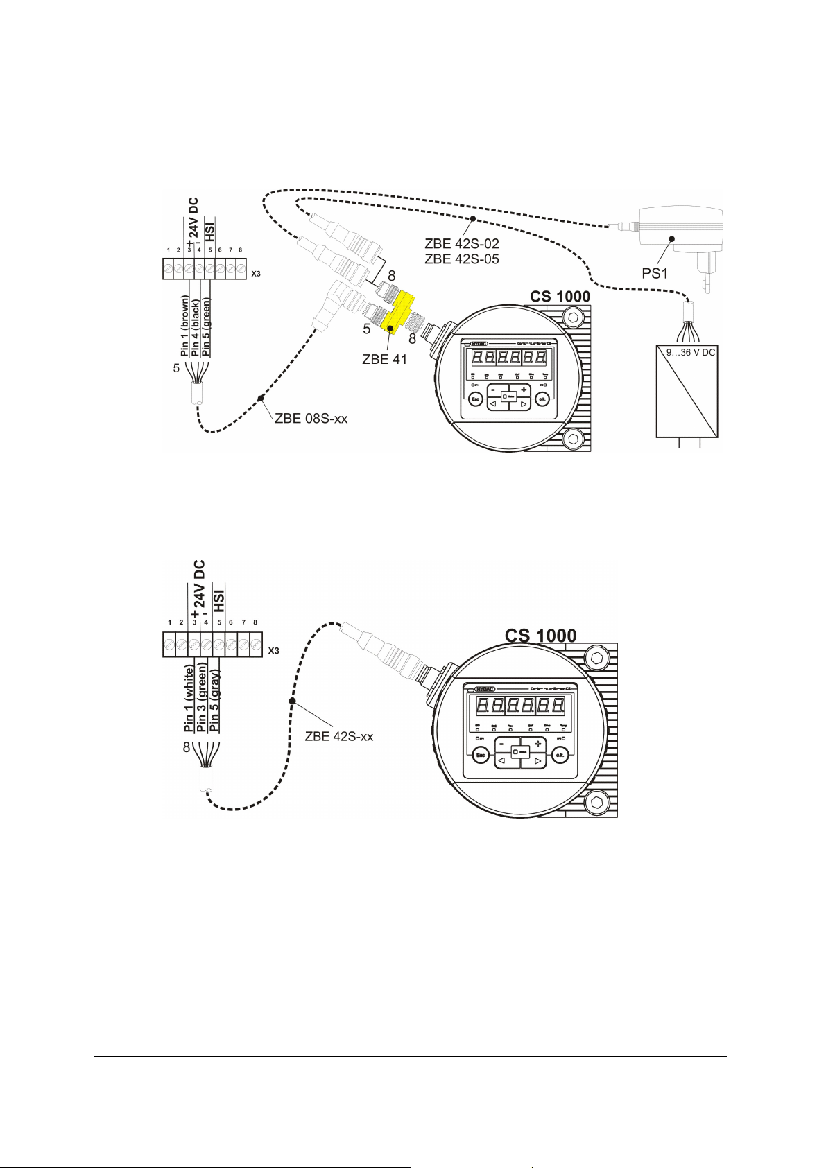
Connecting CS1000 with Hardware Index "a" or "b"
When connecting a CS1000 with the hardware index "a" or "b", use a separate
power supply unit for the voltage supply for the CS1000. Use the Y adapter ZBE41
for this circuit. You will find the part no. in the chapter Accessories on page 30.
Connect the pins 1/3/5 of the CS1000 sensor to the terminals 3/4/5 on terminal
block X3.
Connecting CS1000 with hardware index "c" or later
Connect the pins 1/3/5 of the CS1000 sensor to the terminals 3/4/5 on terminal
block X3.
HYDAC FILTER SYSTEMS GMBH
BeWa CSI-B-1 3424452b 2012-04-20 en-us.doc 2012-04-20
en(us)
Page 15 / 36
Page 16
CSI-B-1 CSI-B-1 Connection Overview
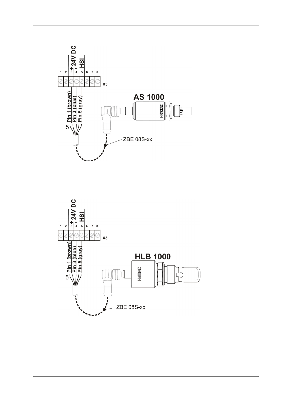
Connecting AS1000
Connect the pins 1/3/5 of the AS1000 sensor to the terminals 3/4/5 on terminal
block X3.
Connecting HLB1000
Connect the pins 1/3/5 of the HLB1000 sensor to the terminals 3/4/5 on terminal
block X3.
HYDAC FILTER SYSTEMS GMBH
BeWa CSI-B-1 3424452b 2012-04-20 en-us.doc 2012-04-20
en(us)
Page 16 / 36
Page 17
CSI-B-1 CSI-B-1 Connection Overview
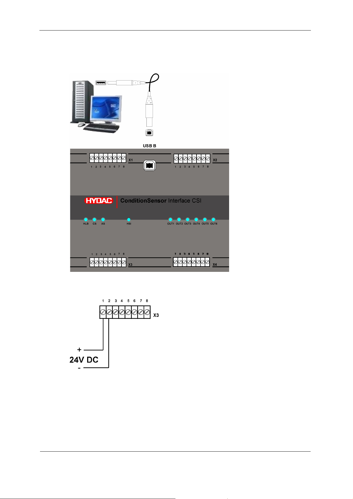
Setting up Connection with PC
Before connecting the CSI-B-1 to the PC, install the USB driver from the support CD
as described below (see page 12).
Connecting the Voltage Supply
Connect the 24 V DC voltage supply with terminals 1 and 2 on the clamp gib X3.
Check that the polarity is correct.
After the voltage has been switched on, the CSI-B-1 begins to operate; the sensors
are supplied with voltage through the CSI-B-1.
If the corresponding sensor is detected at the input, the LED on the CSI-B-1 lights
up green.
HYDAC FILTER SYSTEMS GMBH
BeWa CSI-B-1 3424452b 2012-04-20 en-us.doc 2012-04-20
en(us)
Page 17 / 36
Page 18
CSI-B-1 CSI-B-1 is detected by the PC
g
CSI-B-1 is detected by the PC
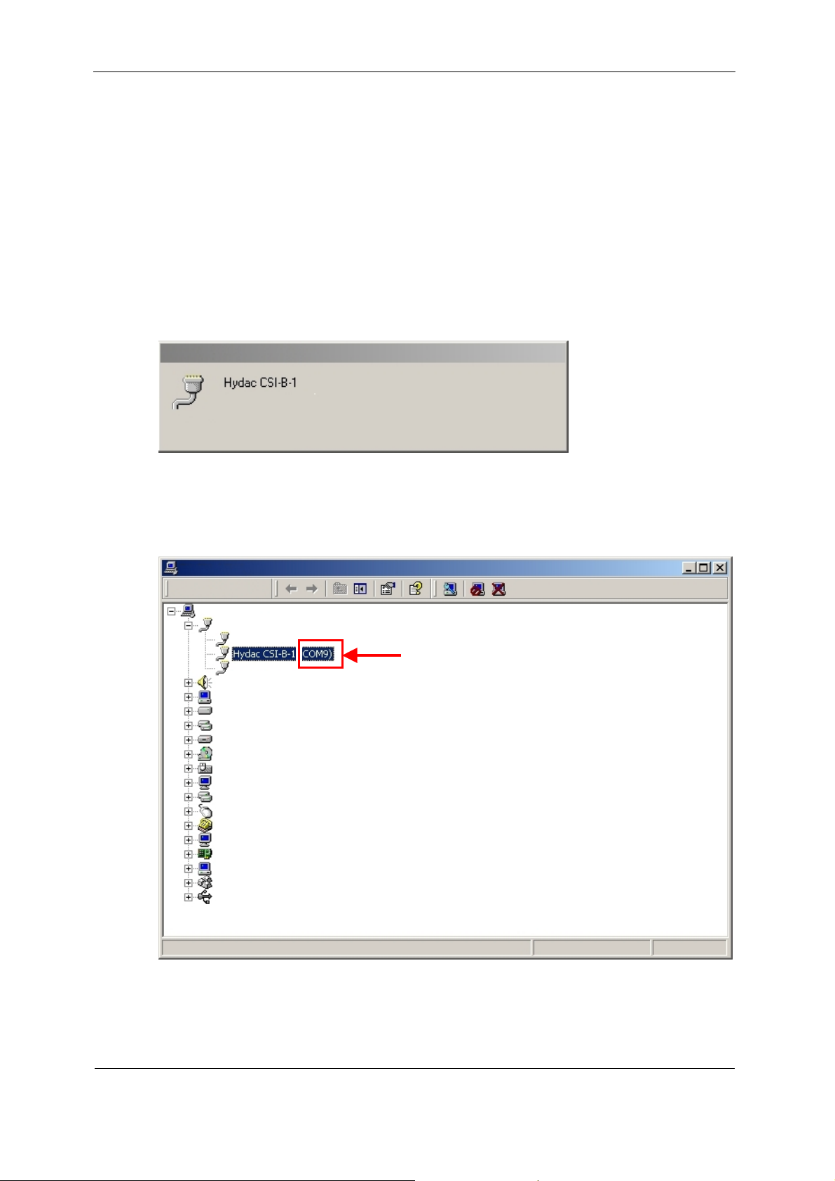
The PC detects the CSI-B-1 after the following steps have been carried out:
- USB driver is installed
- CSI-B-1 is connected with the PC via a USB cable
- the PC is switched on
- the CSI-B-1 is equipped with voltage
You will receive the following message only after the first time the CSI-B-1 is
connected:
New hardware found
Installation ....
This comple
Run the Windows DeviceManager as follows in order to determine the COM
interface at which the CSI-B-1 is now located.
Settings -> System Control -> System -> Hardware -> DeviceManager
De
tes the installation of the CSI-B-1.
viceMana
er
!
If the CSI-B-1 has been detected by the system, then this will be identified in the
DeviceManager with the corresponding COM interface (here: COM9).
Please make a note of this COM interface for yourself. This information will be
needed again when the HyperTerminal is opened.
HYDAC FILTER SYSTEMS GMBH
BeWa CSI-B-1 3424452b 2012-04-20 en-us.doc 2012-04-20
en(us)
Page 18 / 36
Page 19
CSI-B-1 Parameterizing CSI-B-1 with the HyperTerminal
y
Parameterizing CSI-B-1 with the HyperTerminal
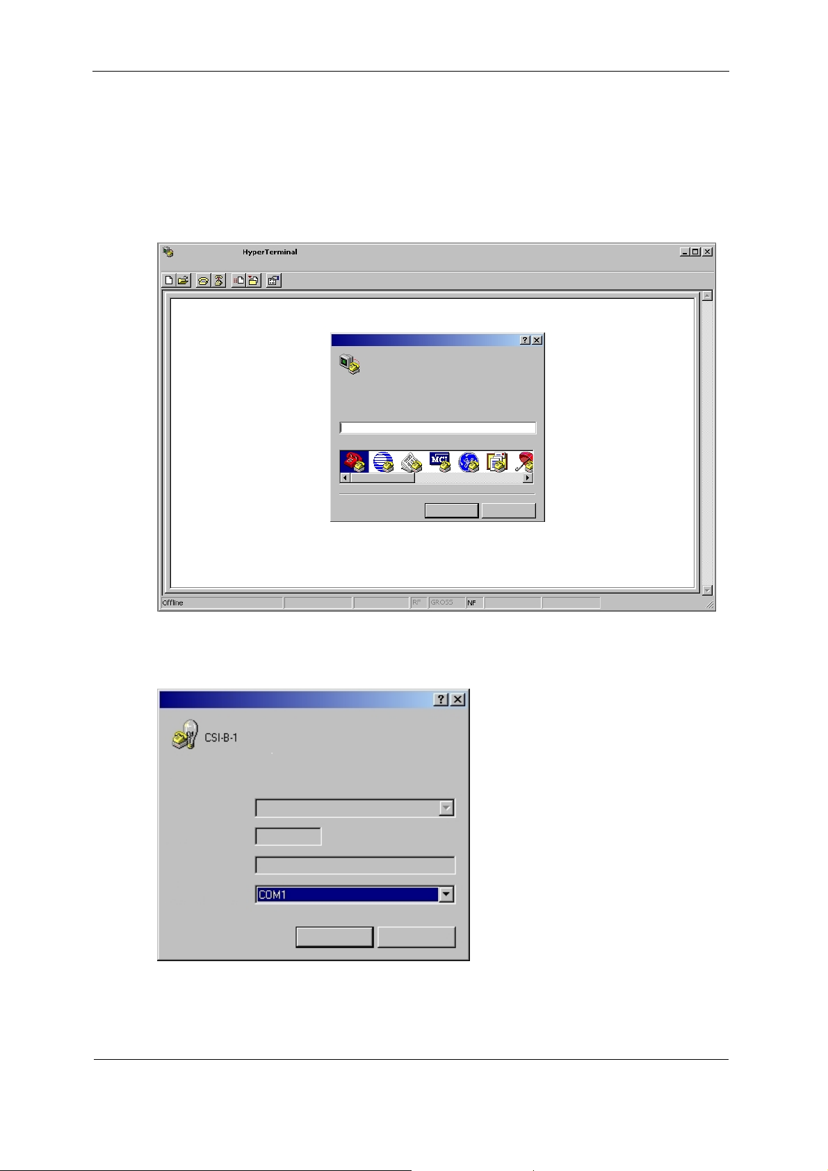
You will require the standard software HyperTermainal to parameterize the CSI-B-1.
This program is part of the Window Standard Installation. You can find it in Windows
under:
Programs -> Accessories -> Communications -> HyperTerminal
Ne
w connection
Name:
CSI-B-1
mbol:
S
OK
Cancel
After the Start you will be prompted to give this connection a
1) and you can select a suitable symbol.
Connect with
Connect via:
name (example: CSI-B-
OK
Cancel
Now select f
or the "Connect via" point the interface which you had determined
previously via DeviceManager (see page 18).
HYDAC FILTER SYSTEMS GMBH
BeWa CSI-B-1 3424452b 2012-04-20 en-us.doc 2012-04-20
en(us)
Page 19 / 36
Page 20
CSI-B-1 Parameterizing CSI-B-1 with the HyperTerminal
Checking/setting interface parameters
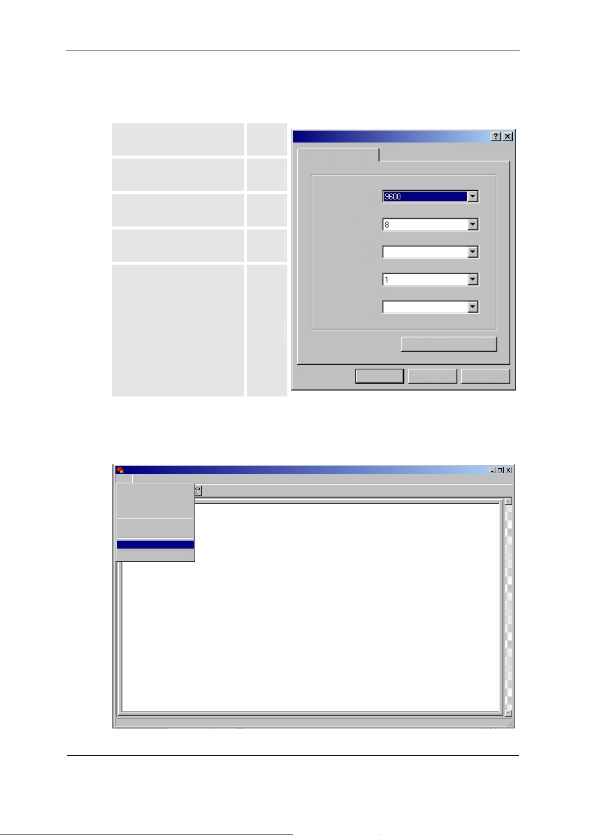
Check the HyperTerminal for the following settings in order to ensure the data
exchange between CSI-B-1 and the PC.
Transfer rate (bps) 9600
Connection settings
Data bit 8
Transfer rate (bps):
Parity No
Data bits:
Stop bits 1
Handshake / Protocol /
Flow control
None
Stop bits:
Flow control:
Parity:
None
None
OK
Restore Standa
Cancel
rd
Apply
The HyperTerminal opens after the acknowledgement of the interface parameters
and the adjustment of the ASCII configuration.
Open the "Properties" of the HyperTerminal via the File menu.
File
New connection
Open...
Save
Print
Properties
Close
HYDAC FILTER SYSTEMS GMBH
BeWa CSI-B-1 3424452b 2012-04-20 en-us.doc 2012-04-20
en(us)
Page 20 / 36
Page 21
CSI-B-1 Parameterizing CSI-B-1 with the HyperTerminal
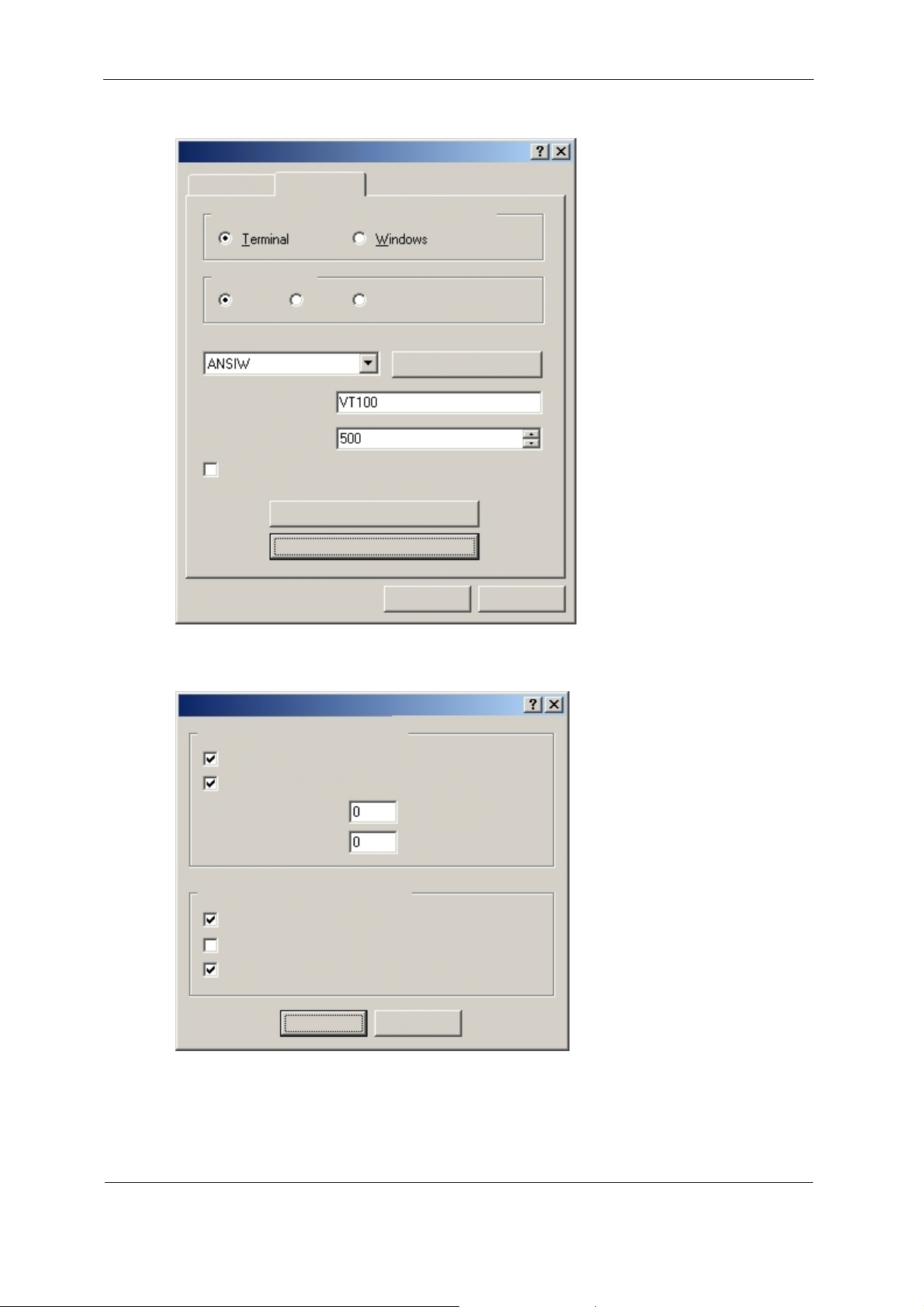
Check the properties for the following settings:
Properties of CSI-B-1
Connect w
Telnet terminal
Lines in image run buffer
ith
Program settings
Assignment of the function, arro
Backspace key
Ctrl+H
Emulation
Acoustic signal when connecting or disconnecting
Translation of the input data
Del
ASCII configuration
Ctrl+H, Empty space, Ctrl+H
w and Ctrl keys
Terminal configuration
OK
Cancel
ACSII configuration:
SCII configuration
A
Settings for ASCII transmission
Lines sent end with line feed
Local outputting of entered character (local echo)
Line delay:
Character delay:
Settings for ASCII reception
Line feed at line end during reception
Receive input data in 7-bit ASCII format
Wrap overlong lines in terminal window
OK
Milliseconds
Milliseconds
Cancel
HYDAC FILTER SYSTEMS GMBH
BeWa CSI-B-1 3424452b 2012-04-20 en-us.doc 2012-04-20
en(us)
Page 21 / 36
Page 22
CSI-B-1 Parameterizing CSI-B-1 with the HyperTerminal
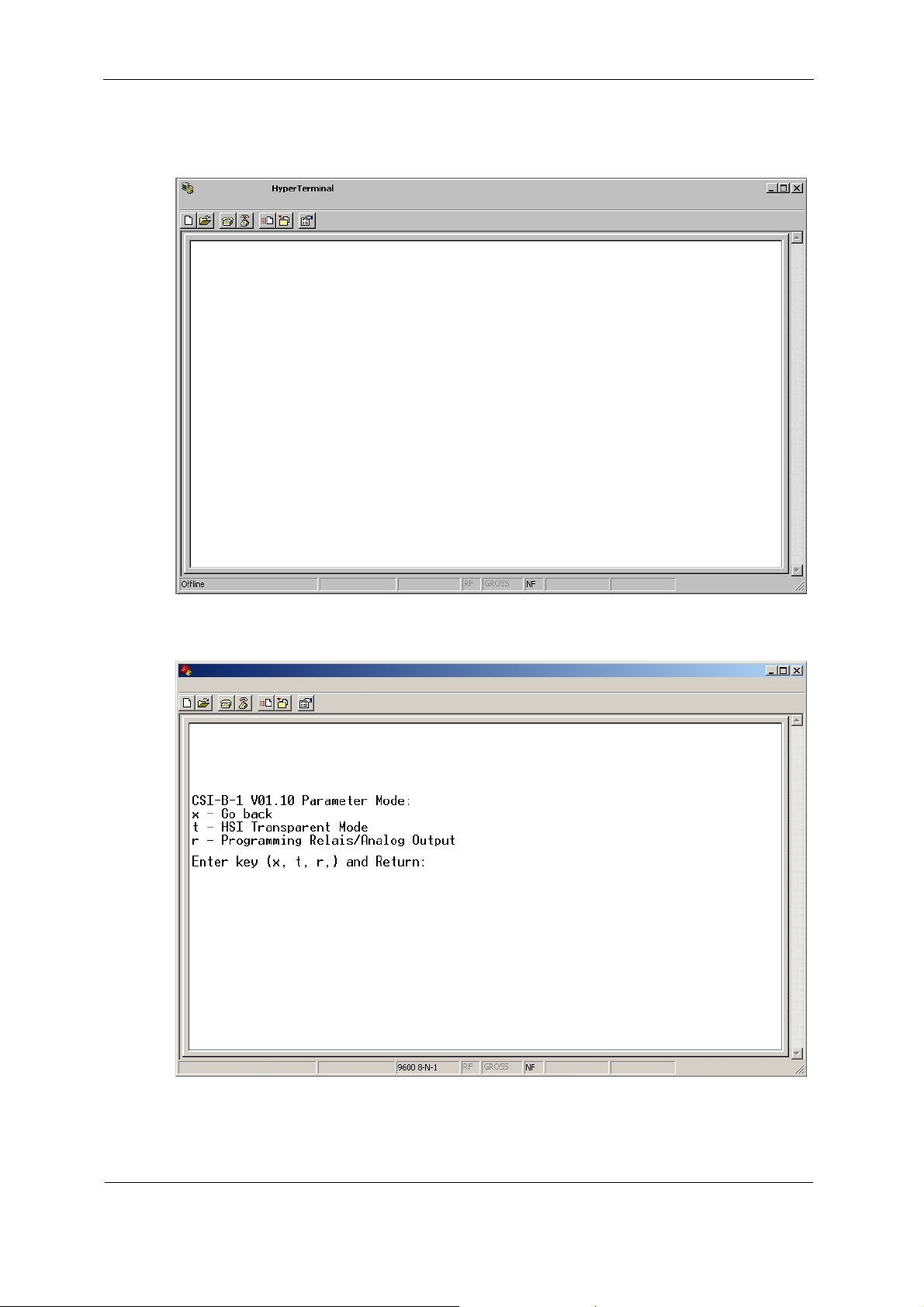
The HyperTerminal is available to you for parameterization after the
acknowledgement of the interface parameters and the adjustment of the ASCII
configuration.
Press the Return key to start the communication with the CSI-B-1.
HYDAC FILTER SYSTEMS GMBH
BeWa CSI-B-1 3424452b 2012-04-20 en-us.doc 2012-04-20
en(us)
Page 22 / 36
Page 23

CSI-B-1 Parameter Mode
Parameter Mode
Parameter Mode:
x - Go back
t - HSI Transparent Mode
r - Programming Relay/Analog Output
Enter key (x, t, r) and Return:
t HSI Transparent Mode: 0
x - Go back
1 - HSI Transparent Mode: On
0 - HSI Transparent Mode: Off
Enter key (x, 0, 1) and Return:
r r – Choose Relay number/Analog Output channel you want to program
a – Configuration Analog Output Function
c – Choose measure channel
f – Choose function of switch
l – Enter limits
x – Go back
Enter key (x, a, c, f, l) and Return:
r Relay number/Analog Output channel: 1
Enter key (x, 1-4) and Return:
a Analog Output channel 1 is: 0
x - Go back
1 - CURRENT Output
0 - VOLTAGE Output
Enter key (x, 0, 1) and Return:
c Relay 1 - Measure channel: 1
CS1000
1=ISO 4, 2=ISO 6, 3=ISO 14, 4=SAE A, 5=SAE B, 6=SAE C,
7=SAE D, 8=Temp, 9=Flow, 10=Drive
HLB1000:
HYDAC FILTER SYSTEMS GMBH
BeWa CSI-B-1 3424452b 2012-04-20 en-us.doc 2012-04-20
en(us)
Page 23 / 36
Page 24

CSI-B-1 HSI Transparent Mode
1=Temperature, 2=Osc. Div., 3=DK. Div., 4=rel. Hum.
AS1000:
1=rel. Hum., 2=abs. Hum., 3=Temperature
Enter key (x, 1-10) and Return:
f Relay 1 - Function of switch: 1
- 1=no function, 2=within range, 3=outside range, 4=exceed,
5=fall below
Enter key (x, 1-5) and Return:
l Relay 1 - Switch values: 10.00 – 20.00
Enter key or Relay switch values (x, Lower Higher(e.g. 10.00
20.00)) and Return:
HSI Transparent Mode
The HSI Transparent Mode can be used to switch the operating mode of the CSI-B1 from:
(off) via limit values and switching statuses of programmable controller and
(on) simple interface converter between HSI <-> USB
Details about paramterization can be found in chapter Parameter Mode.
HYDAC FILTER SYSTEMS GMBH
BeWa CSI-B-1 3424452b 2012-04-20 en-us.doc 2012-04-20
en(us)
Page 24 / 36
Page 25
CSI-B-1 Configuring Analog Output
Configuring Analog Output
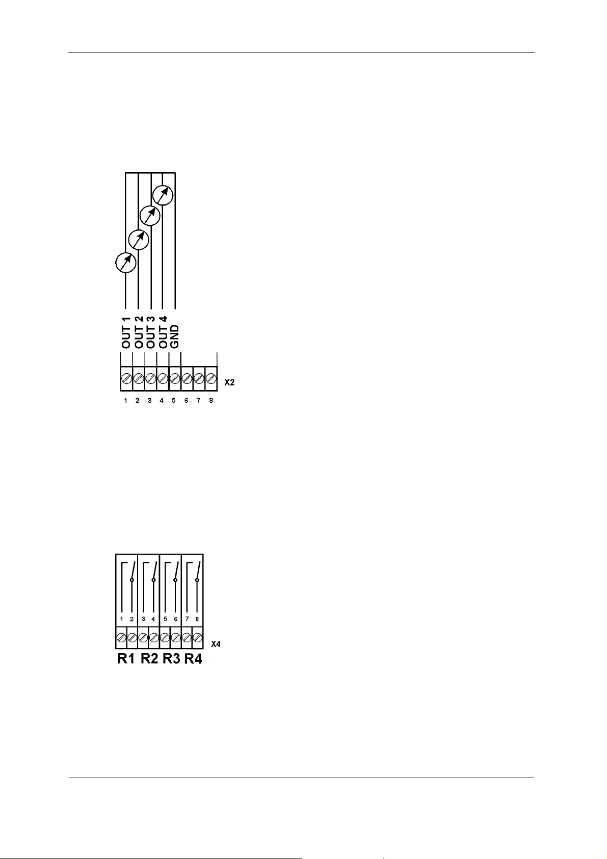
The analog output is parameterizable via the HyperTerminal so that each channel
can be individually used as a current output 4 ... 20 mA (LED = red) or voltage
output 2 ... 10 V (LED = green).
Details about paramterization can be found in chapter Parameter Mode.
Configuring Switching Output R1 / R2 / R3 / R4
The switching output can be parameterized in the following points via HyperTerminal
with respect to:
Switching functions
Limit values
Details about paramterization can be found in chapter Parameter Mode.
HYDAC FILTER SYSTEMS GMBH
BeWa CSI-B-1 3424452b 2012-04-20 en-us.doc 2012-04-20
en(us)
Page 25 / 36
Page 26

CSI-B-1 CS 1000 - Reading out measured values
CS 1000 - Reading out measured values
If a CS 1000 is detected at the sensor input, then the CSI-B-1 outputs the following
analog signals:
Output
OUT1 SAE A (0.0 … 14.0) or ISO >4 µm (9.6 … 23.7)
OUT2 SAE B (0.0 … 14.0) or ISO >6 µm (8.3 … 22.3)
OUT3 SAE C (0.0 … 14.0) or ISO >14 µm (5.8 … 19.8)
OUT4 SAE D (0.0 … 14.0)
The values in the tables can be calculated as follows:
Value Formula
Voltage U = 2 + 8 x SAE class / 14
Current I = 4 + 16 x SAE class / 14
SAE class = (voltage U - 2) x 14 / 8
SAE class = (current I - 4) x 14 / 16
ISO > 4µm ~ SAE A + 9.6
ISO > 6µm ~ SAE B + 8.3
ISO > 14µm ~ SAE C + 5.8
ISO > 21µm ~ SAE D + 3.3
HYDAC FILTER SYSTEMS GMBH
BeWa CSI-B-1 3424452b 2012-04-20 en-us.doc 2012-04-20
en(us)
Page 26 / 36
Page 27

CSI-B-1 CS 1000 - Reading out measured values
Current Voltage SAE ISO ISO ISO
I U A/B/C >4 µm >6 µm >14 µm
4.0 mA 2.0 V 0.0 9.6 8.3 5.8
4.6 mA 2.3 V 0.5 10.1 8.8 6.2
5.1 mA 2.6 V 1.0 10.6 9.3 6.8
5.7 mA 2.9 V 1.5 11.1 9.8 7.2
6.3 mA 3.1 V 2.0 11.6 10.3 7.8
6.9 mA 3.4 V 2.5 12.1 10.8 8.3
7.4 mA 3.7 V 3.0 12.6 11.3 8.8
8.0 mA 4.0 V 3.5 13.1 11.8 9.3
8.6 mA 4.3 V 4.0 13.6 12.3 9.8
9.1 mA 4.6 V 4.5 14.1 12.8 10.3
9.7 mA 4.9 V 5.0 14.6 13.3 10.8
10.3 mA 5.1 V 5.5 15.1 13.8 11.3
10.9 mA 5.4 V 6.0 15.6 14.3 11.8
11.4 mA 5.7 V 6.5 16.1 14.8 12.3
12.0 mA 6.0 V 7.0 16.6 15.3 12.8
12.6 mA 6.3 V 7.5 17.1 15.8 13.3
13.1 mA 6.6 V 8.0 17.7 16.3 13.8
13.7 mA 6.9 V 8.5 18.2 16.8 14.3
14.3 mA 7.1 V 9.0 18.7 17.3 14.8
14.9 mA 7.4 V 9.5 19.2 17.8 15.3
15.4 mA 7.7 V 10.0 19.7 18.3 15.8
16.0 mA 8.0 V 10.5 20.2 18.8 16.3
16.6 mA 8.3 V 11.0 20.7 19.3 16.8
17.1 mA 8.6 V 11.5 21.2 19.8 17.3
17.7 mA 8.9 V 12.0 21.7 20.3 17.8
18.3 mA 9.1 V 12.5 22.2 20.8 18.3
18.9 mA 9.4 V 13.0 22.7 21.3 18.8
19.4 mA 9.7 V 13.5 23.2 21.8 19.3
20.0 mA 10.0 V 14.0 23.7 22.3 19.8
HYDAC FILTER SYSTEMS GMBH
BeWa CSI-B-1 3424452b 2012-04-20 en-us.doc 2012-04-20
en(us)
Page 27 / 36
Page 28

CSI-B-1 HYDACLab - Reading out measured values
HYDACLab - Reading out measured values
If a HYDACLab is detected at the sensor input, then the CSI-B-1 outputs the
following analog signals:
Output Value
OUT1 Temperature T (−25°C … +100°C)
Voltage U = Voltage
2 + 8 x (T + 25°C) / 125°C
U =
Current I = Current
4 + 16 x (T + 25°C) / 125°C
I =
Temperature = ((voltage U − 2) × 125 / 8) − 25
Temperature = ((current I − 4) × 125 / 16) − 25
OUT2 Rel. change in the dielectric constant rDK (−30 % … +30 %)
Voltage U = Voltage
2 + 8 x (rDK + 30%) / 60%
U =
Current I = Current
4 + 16 x (rDK + 30%) / 60%
I =
rDK = rDK =
((voltage U − 2) × 60 / 8) − 30
rDK = rDK = ((current I − 4) × 60 / 16) − 30
OUT3 Saturation level S (0 ... 100 %)
Voltage U = Voltage
2 + 8 x S / 100
U =
Current I = Current
4 + 16 x S / 100
I =
S = (voltage U − 2) × 100 / 8
S = (current I − 4) × 100 / 16
HYDAC FILTER SYSTEMS GMBH
BeWa CSI-B-1 3424452b 2012-04-20 en-us.doc 2012-04-20
en(us)
Page 28 / 36
Page 29

CSI-B-1 AS 1000 - Reading out measured values
AS 1000 - Reading out measured values
If an AS 1000 is detected at the sensor input, then the CSI-B-1 outputs the following
analog signals:
Output Value
OUT1 Saturation level S (0 ... 100 %)
Voltage U = Voltage
2 + 8 x S / 100%
U =
Current I = Current
4 + 16 x S / 100%
I =
S = (voltage U − 2) × 100 / 8
S = (current I − 4) × 100 / 16
OUT2 Temperature T (−25 … +100°C)
Voltage U = Voltage
2 + 8 x (T + 25°C) / 125°C
U =
Current I = Current
4 + 16 x (T + 25°C) / 125°C
I =
Temperature = (voltage U − 2) × 125 / 8
Temperature = (current I − 4) × 125 / 16
HYDAC FILTER SYSTEMS GMBH
BeWa CSI-B-1 3424452b 2012-04-20 en-us.doc 2012-04-20
en(us)
Page 29 / 36
Page 30
CSI-B-1 Accessories
Accessories
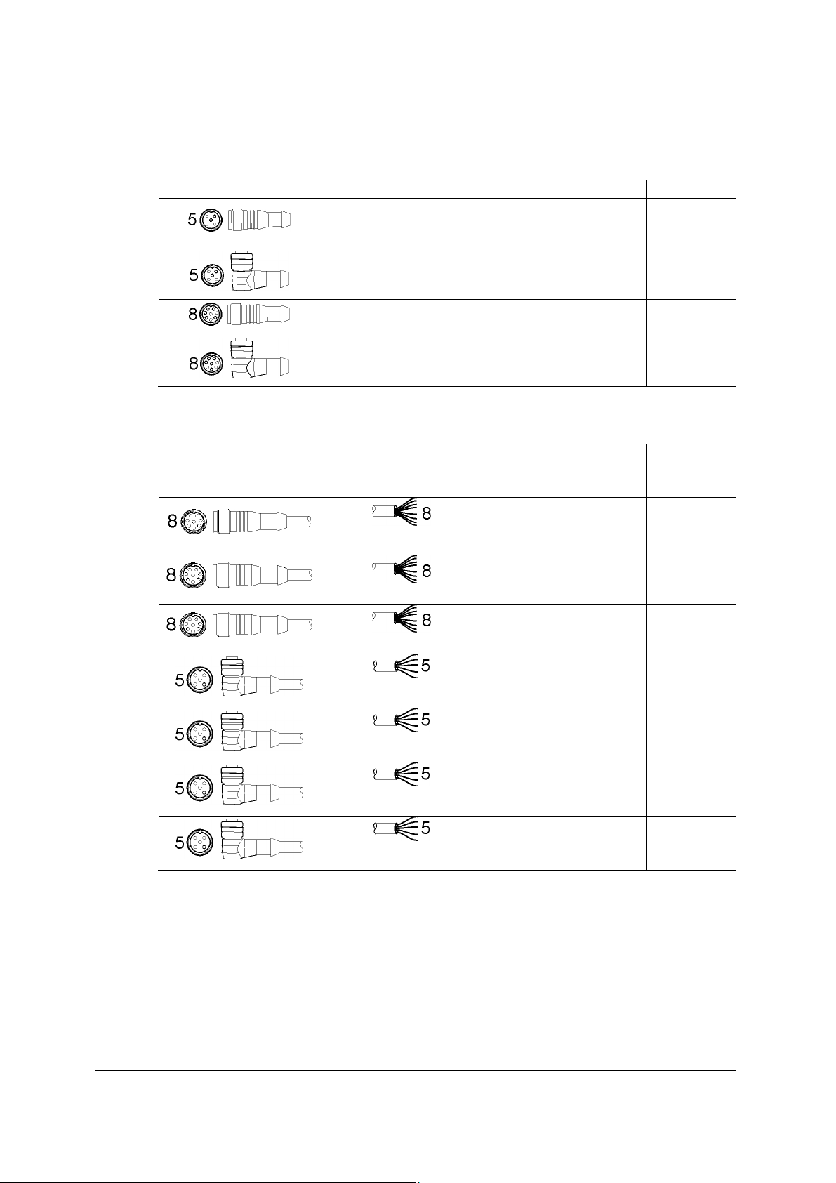
Plugs
Connector female with screw
clamp, screened
Connector female with screw
Connector female with screw
Connector female with screw
Connection Cable, Shielded
Connector female
↔
↔
↔
Part no.
clamp, screened
clamp, screened
clamp, screened
Cable
ending
open
+
screen
+
screen
Length Part no.
6049128
ZBE 08 6006786
ZBE 44 3281243
ZBE 0P 6055444
2 m ZBE 42S-02 3281220
5 m
ZBE 42S-05 3281239
↔
↔
↔
↔
↔
screen
screen
screen
screen
screen
+
+
+
+
+
10 m
2 m ZBE 08S-02 6019455
5 m ZBE 08S-05 6019456
10 m ZBE 08S-10 6023102
30 m ZBE 08S-30 6035063
ZBE 42S-10 6072262
HYDAC FILTER SYSTEMS GMBH
BeWa CSI-B-1 3424452b 2012-04-20 en-us.doc 2012-04-20
en(us)
Page 30 / 36
Page 31
CSI-B-1 Accessories
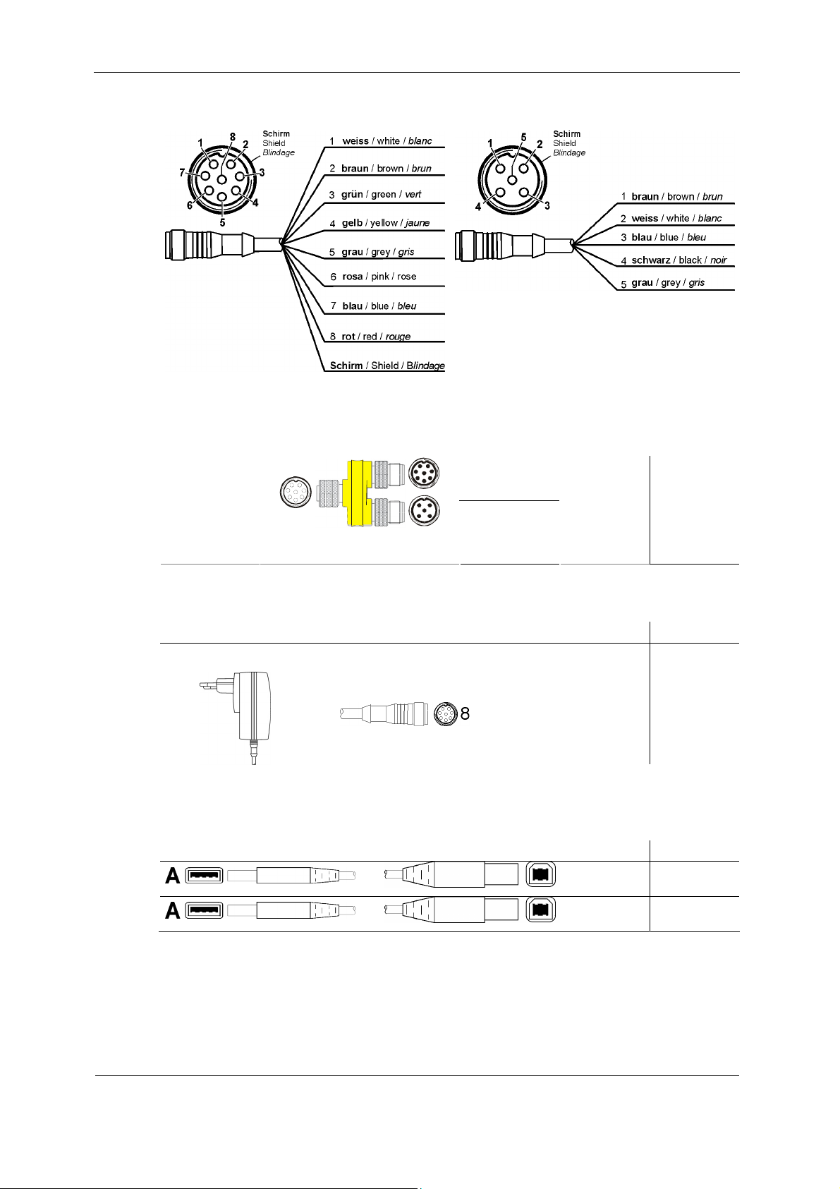
Cable Coding
Y-Adaptor
Coupling
Coupling
socket
8
8
5
Color: yellow
plug
Coupling
plug
ZBE 41
910000
Power Supply Unit for CS1000
Power supply unit
100 – 240 V AC, 50-60
Hz, 0.4 A
↔
Connector female Length Part no.
15 V DC, 500 mA
↔
↔
USB - Connection Cable
Connector female
↔
↔
↔ 5 m
1.8 m
Connector female Length Part no.
PS1
1.8 m 6064127
3376530
6064126
HYDAC FILTER SYSTEMS GMBH
BeWa CSI-B-1 3424452b 2012-04-20 en-us.doc 2012-04-20
en(us)
Page 31 / 36
Page 32

CSI-B-1 Disposing of the CSI-B-1
Disposing of the CSI-B-1
Please dispose of the packaging material in an environmentally friendly manner.
After dismantling the unit and separating the various materials, dispose of the unit in
an environmentally friendly manner.
Model Code
The following model code is valid for this product:
CSI - B - 1 - 000
Product series
CSI = ConditionSensor Interface
Housing
B = Top hat rails housing
Signal output
1 = HSI -> analog output
Modification
000 = Standard
HYDAC FILTER SYSTEMS GMBH
BeWa CSI-B-1 3424452b 2012-04-20 en-us.doc 2012-04-20
en(us)
Page 32 / 36
Page 33

CSI-B-1 Model Code
Technical Data
General data
Dimensions 142 x 105 x 35
Securing the ERF Intended for installation on size 35 top hat
rails in accordance with EN 60715
Mounting position Arbitrary
Ambient temperature range
IP class
Weight
-40 … 85 °C
IP40
0.35 kg
Electrical data
Connection plug USB (B), 4 x 8-way clamp gibs
Supply voltage 24 V DC, residual ripple <10%, (protected
against polarity reversal)
Power consumption 0.6 Watt max.
Analog output 2-conductor technology
4 - 20 mA active output (max. burden 500Ω)
or
2 - 10 V active output (min. load resistor
820Ω)
Deviations: +/-1%
Switching output Relay with
max. switching current 3 A,
max. switching voltage 220 V DC / 250 V AC,
dead open
HSI (HYDAC Sensor Interface) 1 wire, half duplex
HYDAC FILTER SYSTEMS GMBH
BeWa CSI-B-1 3424452b 2012-04-20 en-us.doc 2012-04-20
en(us)
Page 33 / 36
Page 34

Notes
Page 35

Notes
Page 36

HYDAC FILTER SYSTEMS GMBH
Industriegebiet Postfach 1251
66280 Sulzbach / Saar 66273 Sulzbach / Saar
Germany Germany
Phone: +49 (0) 6897 509 01 Central
Fax: +49 (0) 6897 509 846 Technical Department
Fax: +49 (0) 6897 509 577 Sales Department
Internet: www.hydac.com
Email: [email protected]
 Loading...