

Page 1

Hustler 3500/3700 Catcher
Owner’s Manual
111782_0910
•••••
P.O. Box 7000
•••
Hesston, Kansas
•
67062-2097
Page 2

t-2 109686_0910
Page 3

TABLE OF CONTENTS
General Information . . . . . . . . . . . . . . . . . . . . . . . . . . . . . . . . . . 1-1
Safety Precautions. . . . . . . . . . . . . . . . . . . . . . . . . . . . . . . . . . . . 2-1
Assembly Instruction . . . . . . . . . . . . . . . . . . . . . . . . . . . . . . . . . 3-1
Operation . . . . . . . . . . . . . . . . . . . . . . . . . . . . . . . . . . . . . . . . . . 4-1
Maintenance . . . . . . . . . . . . . . . . . . . . . . . . . . . . . . . . . . . . . . . . 5-1
Storage . . . . . . . . . . . . . . . . . . . . . . . . . . . . . . . . . . . . . . . . . . . . 6-1
Parts Manual . . . . . . . . . . . . . . . . . . . . . . . . . . . . . . . . . . . . . . . . 7-1
111782_0910 t-1
Page 4

t-2 111782_0910
Page 5

GENERAL INFORMATION
This manual applies to the following equipment:
Catcher, 929455
60” Blower, 929430
72” Blower, 929448
To the new owner
The purpose of this manual is to assist owners and operators
in maintaining and operating the catcher for the 3500/3700
tractors and decks. Please read it carefully; information and
instructions furnished can help you achieve years of
dependable performance.
Using this manual
General operation, adjustment and maintenance guidance is
outlined for both the experienced and novice Hustler user.
Operating conditions vary considerably and cannot all be
addressed individually. Through experience, however,
operators should find no difficulty in developing good
operating skills suitable to most conditions.
Directions used in this manual, for example RIGHT or
LEFT, refer to directions when seated on tractor facing
forward, unless otherwise stated.
Photographs and illustrations used were current at the time
of printing, but subsequent production changes may cause
your machine to vary slightly in detail. Hustler Turf
Equipment reserves the right to redesign and change the
machine as deemed necessary, without notification. If a
change has been made to your machine which is not reflected
in this owner’s manual, or the parts manual, see your Hustler
dealer for current information and parts.
Warranty registration
The Delivery and Warranty Registration form must be
completed and signed to validate your warranty protection.
As the new equipment owner, you are expected to see that the
card is completed and forwarded to Hustler Turf Equipment at
time of delivery.
Be sure to register the tractor plus each attachment that
displays a model and serial identification number plate with
Hustler Turf Equipment.
IMPORTANT: Any unauthorized modification, altera-
tion, or use of non-approved attachments voids the warranty
and releases Hustler Turf Equipment from any liability arising
from subsequent use of this equipment.
Parts and service
Use original Hustler replacement parts only. These parts
are available through your local Hustler dealer. To obtain
prompt, efficient service, always provide the following
information when ordering parts:
1. Correct part description and number, as given in the
parts manual supplied with your owner’s packet.
2. Correct model number.
All warranty repair and service must be handled through an
authorized Hustler dealer. Arrangements should be made
through your local service center.
111782_0910 1-1
Page 6

1-2 111782_0910
Page 7
SAFETY PRECAUTIONS
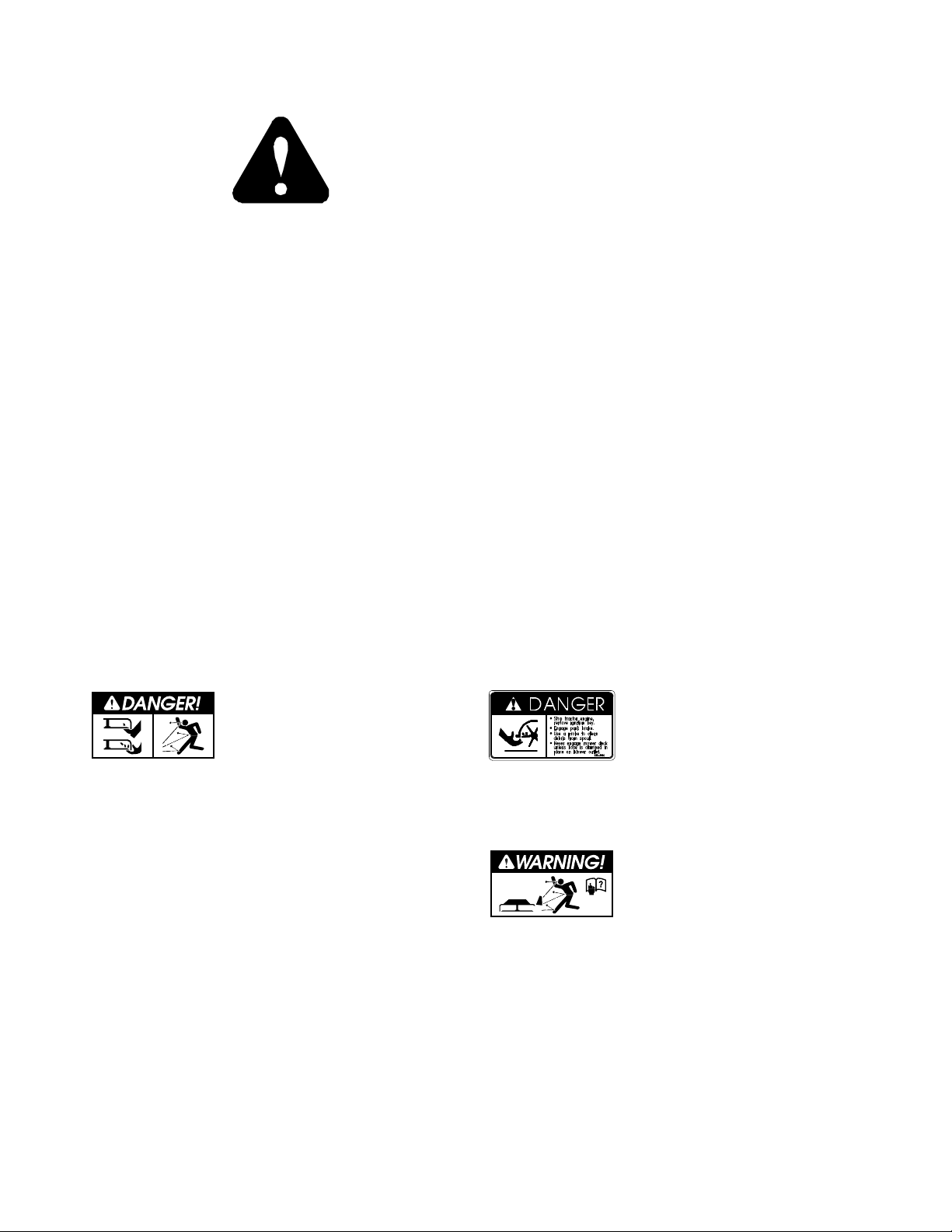
This safety alert symbol is used to call attention to a
message intended to provide a reasonable degree of
PERSONAL SAFETY for operators and other persons
during the normal operation and servicing of this equipment.
DANGER – Denotes immediate hazards which WILL
result in severe personal injury or death.
WARNING – denotes a potential hazard or unsafe practice
which COULD result in severe personal injury or death.
All operators should read this manual and be instructed
about safe operating and maintenance procedures. This is the
owner’s responsibility.
Incorrect usage of this machine may result in severe
injury. It is the owner’s responsibility that all operators
read this manual thoroughly and be properly trained in
operation and maintenance before attempting to set-up,
adjust, or service this machine. This owner’s manual
contains many safety precautions that must be followed to
avoid injury.
V Park the machine on level ground. Place park brake
lever in the brake engaged position, place the PTO
lever in the “OFF” position, lower the attachment, shut
off engine and remove ignition key before leaving
operator’s seat for any reason including unclogging the
chute.
V Always be aware of any obstructions, especially small
children, when backing or when unloading the catcher.
V Always keep safety shields and covers in place while
operating machine.
V Stop the engine before removing any part of the grass
catcher or unclogging the discharge chute. Never clear
teh discharge chute with the engine running. Turn off
the engine and be sure the blades have stopped before
cleaning. Use a stick to clear a plugged discharge area.
Never use your hands!
V Grass collection system components are subject to
wear, damage, and deterioration, which could expose
moving parts or allow objects to be thrown. Frequently
check components and replace with manufacturer’s
recommended parts, as necessary.
V Never work on blower assembly or mower deck when
the tractor engine is running.
V Never operate machine with catcher in the dump
position.
V Never attempt high speed maneuvering in crowded or
congested areas.
V Always operate with complete catcher system or side
discharge chute in place.
Whirling blades! Keep hands
and feet away.
Beware of thrown objects.
Stop tractor engine, remove ignition key.
Engage park brake.
Use a probe to clean debris from
spout.
Never engage mower deck
unless hose is clamped in place
on blower outlet.
Never operate the mower deck
with the deflector removed or in
a raised position, except when
the grass catching att achment is
being used.
111782_0910 2-1
Page 8

2-2 111782_0910
Page 9

ASSEMBLY INSTRUCTION
These instructions apply to the assembly of the Hustler
Catcher to a Hustler 3500/3700 tractor equipped with a 60” or
72” side discharge deck.
It is intended that these units be installed by trained Hustler
service personnel. If additional assistance is required, contact
the Hustler Customer Service Department.
Directions given in these instructions, for example left and
right, refer to direction while seated on the tractor.
Before proceeding, read thru the following instructions to
familiarize yourself, while at the same time identify and
inventory kit parts supplied.
Unpack and inspect all parts. Notify carrier of any shipping
damages immediately.
Packing list - 929455 Catcher
PART NO. DESCRIPTION QTY.
PECA1089 BOX ASSEMBLY 1
PECB0212 FRAME SUPPORT BRACE 1
PECA0578 REAR SUPPORT FRAME 1
PECA1001 PIVOT HANDLE 2
PECK1231 1/2”-13x 1” HHCS 2
PECK0364 3/4”-10 x 1-1/2” HHCS 2
PECK1433 3/4”-10 NYLOC NUT 2
PECK1432 3/8”-16 U-BOLT 2
PECK1215 3/8”-16 FLANGE NUT 4
PECK0331 1/2”-13 U-BOLT 2
PECK1247 1/2”-13 NYLOC NUT 4
PECK0055 1/2” FLAT WASHER 4
Packing list - 929430 60” Blower
INDEX NO. PART NO. DESCRIPTION QTY.
1 704916 CS .250-20X1.250 HX G5 3
2 768515 FW .281X.625X.051/.080H 6
3 111901 BOX PLATE SUPPORT 1
4 111915 CHUTE SUPPORT 1
5 111902 THICK GUIDE SPACER 1
6 111903 THIN GUIDE SPACER 1
7 111904 CHUTE GUIDE 1
8 024927 NT .250-20 HX GR.5 ZNYC 3
9 111638 CATCHER WEIGHT FULL 2
10 111639 CATCHER WEIGHT HALF 1
11 111448 PULLEY COVER 1
12 078949 CS .500-13X2.000 G5 ZNY 1
13 752386 CW .515X 2.25X .204 BLK 1
14 787986 BELT, B 46" EL 1
15 524785 PULLEY, DOUBLE 6.0 1.0 1
602244 PULLEY, DBL 5.02/6.87EOD (NOT
SHOWN)
16 023036 HP .148 X2.690 ZN 1
17 019471 CE .380X1.75 .150X1.60 1
18 103036 CHUTE MOUNT 1
19 086660 NT .375-16 HXZY NL 4
20 767954 FW .406X .812 X.060 SAE 4
21 109716 HOOK, BLOWER TUBE 1
22 036236 CS .312-18X1.000 HX G5 2
23 768523 FW .343X.687X.051/.080H 4
24 025395 CB .375-16X 1.00 STD CD 3
1
INDEX NO. PART NO. DESCRIPTION QTY.
25 710194 CB .375-16X 1.50 STD G5 1
26 107045 60" XR7 BLOWER SPACER 1
27 058766 NT .312-18 HXZY NL 2
28 111445 BLOWER GUARD 60" 1
29 102913 BLOWER PIVOT MOUNT 1
30 111920 PECO ELBOW 1
31 111849 TUBE SUPPORT 2
32 111852 LOWER TUBE W/A/ 1
33 601229 TRANSITION TUBE, LOWER 1
34 601640 BUNGEE STRAP 1
35 056077 CS .250-20 X 1.00 HX G5 ZN 1
36 068551 NT .250-20 HX NL ZN 1
37 768523 FW .343X.687X.051/080 HD ZN/YL 8
38 064014 CS .312-18 X .875 HS G5 ZN 2
39 064006 CS .312-18 X .625 HX G5 ZN 4
40 058776 NT .312-18 HX NL ZN 2
41 760306 FLEXIBLE TRANSFER TUBE 1
42 022608 HOSE CLAMP 2
43 544501 BLOWER ASSEMBLY 1
Packing list - 929448 72” Blower
INDEX NO. PART NO. DESCRIPTION QTY.
1 704916 CS .250-20X1.250 HX G5 3
2 768515 FW .281X.625X.051/.080H 6
3 111901 BOX PLATE SUPPORT 1
4 111915 CHUTE SUPPORT 1
5 111902 THICK GUIDE SPACER 1
6 111903 THIN GUIDE SPACER 1
7 111904 CHUTE GUIDE 1
8 024927 NT .250-20 HX GR.5 ZNYC 3
9 111638 CATCHER WEIGHT FULL 2
10 111639 CATCHER WEIGHT HALF 1
11 111452 PULLEY COVER 1
12 078949 CS .500-13X2.000 G5 ZNY 1
13 752386 CW .515X 2.25X .204 BLK 1
14 787986 BELT, B 46" EL 1
15 524785 PULLEY, DOUBLE 6.0 1.0 1
602244 PULLEY, DBL 5.02/6.87EOD (NOT
SHOWN)
16 023036 HP .148 X2.690 ZN 1
17 019471 CE .380X1.75 .150X1.60 1
18 103036 CHUTE MOUNT 1
19 086660 NT .375-16 HXZY NL 4
20 767954 FW .406X .812 X.060 SAE 4
21 109716 HOOK, BLOWER TUBE 1
22 036236 CS .312-18X1.000 HX G5 2
23 768523 FW .343X.687X.051/.080H 4
24 025395 CB .375-16X 1.00 STD CD 3
25 710194 CB .375-16X 1.50 STD G5 1
26 058766 NT .312-18 HXZY NL 2
27 111449 BLOWER GUARD 72" 1
28 102913 BLOWER PIVOT MOUNT 1
30 111920 PECO ELBOW 1
31 111849 TUBE SUPPORT 2
32 111852 LOWER TUBE W/A/ 1
33 601229 TRANSITION TUBE, LOWER 1
34 601640 BUNGEE STRAP 1
1
111782_0910 3-1
Page 10
INDEX NO. PART NO. DESCRIPTION QTY.
Cup washer
Bolt
Blower pivot
mount
Chute
mount w/a
Double
pulley
Spring
Belt
35 056077 CS .250-20 X 1.00 HX G5 ZN 1
36 068551 NT .250-20 HX NL ZN 1
37 768523 FW .343X.687X.051/080 HD ZN/YL 8
38 064014 CS .312-18 X .875 HS G5 ZN 2
39 064006 CS .312-18 X .625 HX G5 ZN 4
40 058776 NT .312-18 HX NL ZN 2
41 760306 FLEXIBLE TRANSFER TUBE 1
42 022608 HOSE CLAMP 2
43 544501 BLOWER ASSEMBLY 1
Mower deck preparation
1. Park the tractor on a flat surface and place the park brake
lever in the brake engaged position, place the PTO lever
in the “OFF” position and lower the attachment. Shut off
the ignition switch and remove the key from the switch.
Disconnect the negative battery cable.
2. Remove the right side pulley cover, discharge chute and
discharge chute bracket.
NOTE: Retain these parts as they will be re-installed
when the catcher is removed.
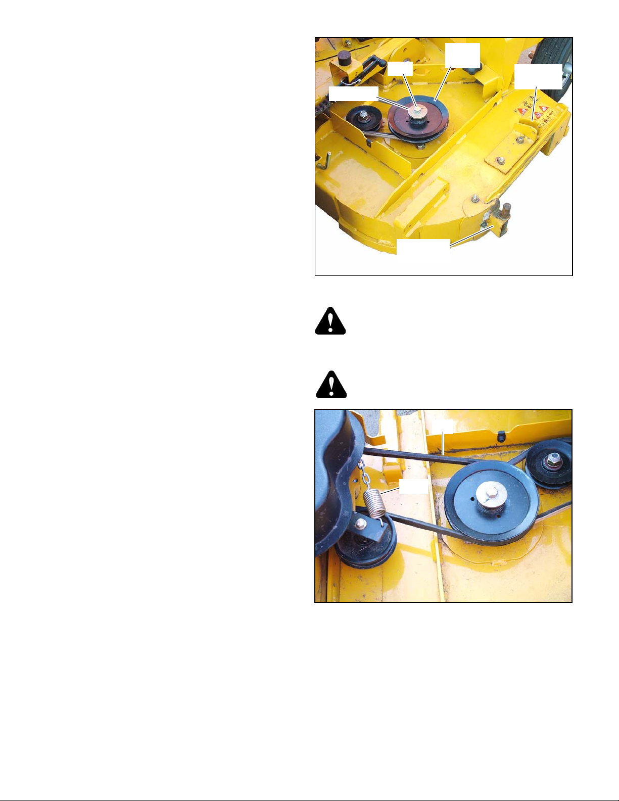
3. Release the deck belt tension. Remove the existing
spindle bolt and pulley from the right side blade spindle.
Replace the pulley with the double pulley and place the
existing cup washer between the head of the new bolt and
the drive pulley. Torque the bolt into the pulley before
threading the bolt into the spindle shaft. Torque top
spindle bolt to 118 ft.-lbs. Thread the pulley, cup washer
and bolt assembly into the right hand spindle shaft.
Torque bol t to 118 ft.-lbs. Figure 3-1
NOTE: There are two double pul leys shipped with this
catcher. Two different deck gearboxes have been used on
these decks.
Decks built prior to serial number 09080000 – The
gearbox is painted black and the pulley is held onto the
drive shaft with set screws. Use pulley, 602244, on these
decks.
Decks built with serial number 09080000 and later –
The gearbox on these decks is painted gray. The pulley is
held onto the drive shaft with a cap screw. Use pulley,
524785, on these decks.
CE Decks regardless of serial number – The gearbox is
painted black and the pulley is held onto the drive shaft
with set screws. Use pulley, 602244, on these decks.
4. Attach the blower mount to the top of the deck. Figure 3-
1
5. Attach the blower assembly to the deck mount. Figure 3-
6. Re-adjust the blower pivot mount, if necessary, to
1
minimize the gap between the deck opening and blower
housing. Tighten all hardware.
7. Install and route the blower belt to the deck. Tension the
belt using the chain and spring. Pull the chain until the
spring extension is 6” hook to hook. Figure 3-2 & Figure
3-3
8. Re-tension the deck drive belt.
9. Attach the pulley cover.
10. Swing the housing so that it is tight against the deck and
insert the clevis pin and hair pin thru the latch..
Figure 3-1
WARNING: Do not operate deck without discharge
chute or complete catcher system in place.
Tractor Preparation
WARNING: Allow engine and muffler to cool before
assembling the unit to the tractor.
Figure 3-2
1. Position the rear support frame and the weights (centered
side to side) to the rear of the tractor . Make sure the upper
holes in the rear support frame are positioned as shown.
Attach with the hardware shown. Figure 3-10
NOTE: It is recommended that 3 people assist when
attaching the box assembly to the rear support frame.
2. Locate the box assembly onto the rear support frame and
attach to the rear support frame with the hardware shown.
Figure 3-10
3-2 111782_0910
Page 11
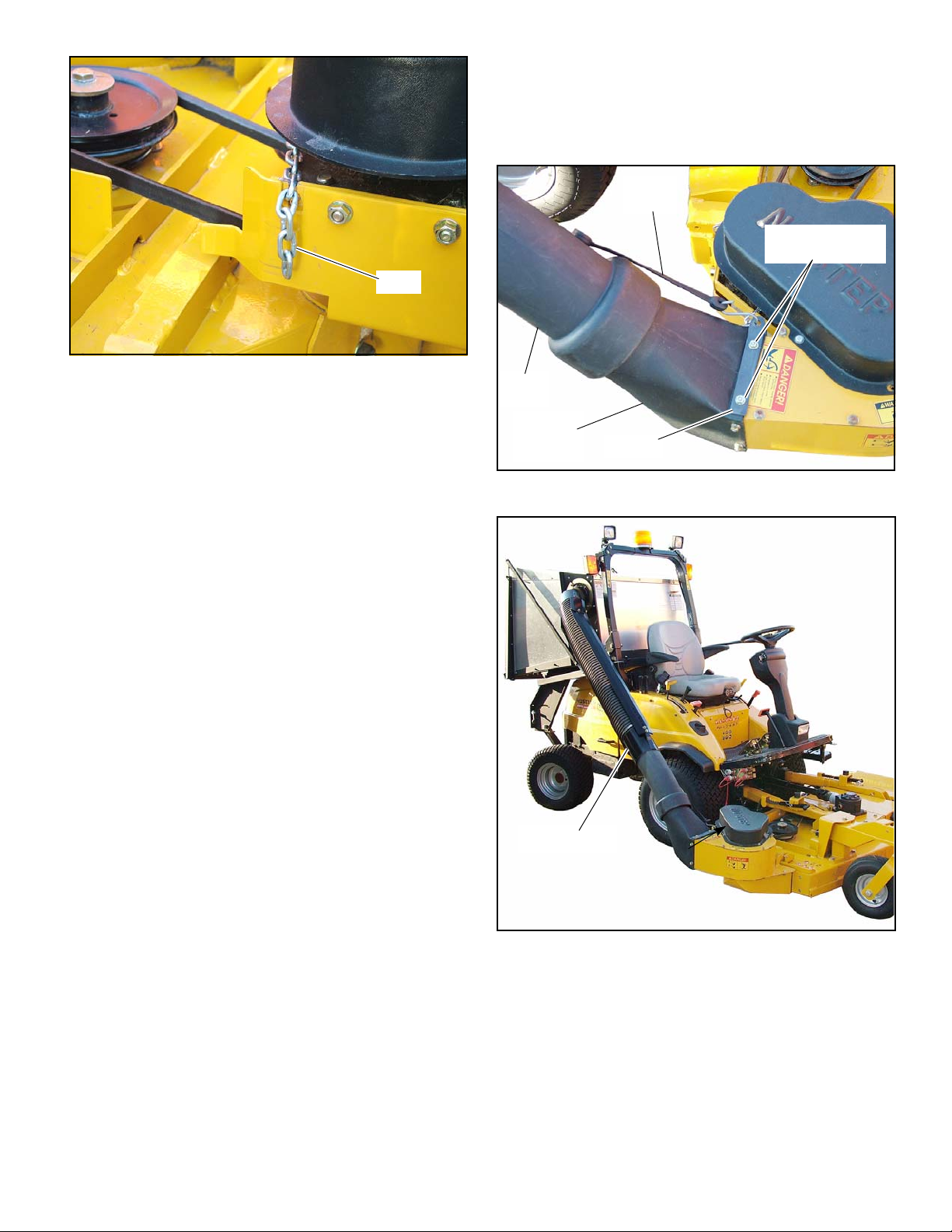
Figure 3-3
Chain
Remove these nuts
and flat washers
Bungee
strap
109716
Blower
housing
tube
Lower
tube
Tube assembly
3. Locate the frame support brace onto the tractor’s ROPS
with the short end of the bend facing upwards and to the
rear of the tractor. Figure 3-11
Raise the support brace until the pins from the box
support frame rest inside the notches in the support brace.
Secure in place using the hardware shown. Tighten all
nuts and bolts.
4. Test to make sure the dump mechanism is working
properly. Pull the lift handle towards the operator’s seat
and lift upward. The container’s door should open and the
box should pivot towards the ground. If the dump
mechanism needs adjusted, refer to the Adjusting dump
mechanism section found elsewhere in this manual for
detailed information.
5. Attach the bungee cord, located on the lower tube, to the
blower tube hook. Figure 3-4
6. Reconnect the negative battery cable. NOTE: Refer to
the Accessing the engine compartment section, found
elsewhere in this manual, for detailed information.
Figure 3-4
Catcher Box Preparation
1. Install the box plate support, chute support, thick guide
spacer, thin guide spacer and chute guide to the side of
the box assembly per Figure 3-7 or Figure 3-8
Final Connection
1. Assemble the blower tube per Figure 3-9.
2. Remove the top two nuts and flat washers that attach the
blower housing tube to the blower housing. Slide the
blower tube hook (109716) onto these bolts and secure in
place with the nuts and flat washers. Figure 3-4
3. Slide the lower tube onto the blower housing tube. Figure
3-4
4. Adjust the length of the blower tube assembly until the
top tube flange can slide into the box assembly’s inlet
mount. Secure in place with the chute guide (111904).
Tighten chute guide hardware. Figure 3-6
Figure 3-5
111782_0910 3-3
Page 12
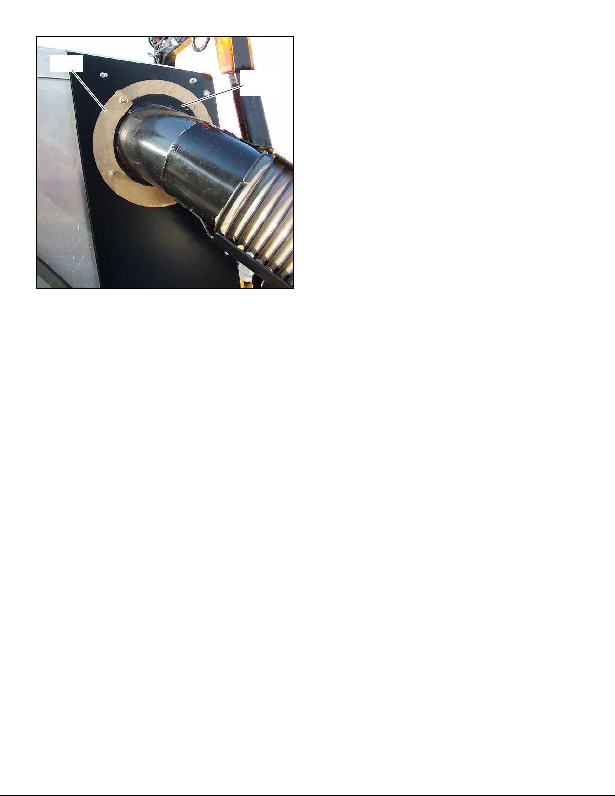
111904
Top tube
flange
Figure 3-6
3-4 111782_0910
Page 13

929430 – 60” Deck
1
2
3
4
5
6
7
2
8
11
12
13
14
15
16
17
20
21
22
23
25
27
23
28
29
19
19
18
19
24
20
EXISTING
HARDWARE
EXISTING
HARDWARE
EXISTING
HARDWARE
26
43
Figure 3-7
111782_0910 3-5
Page 14

929448 – 72” Deck
1
2
3
4
5
6
7
2
8
11
12
13
14
15
16
17
20
21
22
23
25
26
23
27
28
20
20
18
19
24
19
EXISTING
HARDWARE
EXISTING
HARDWARE
EXISTING
HARDWARE
43
Figure 3-8
3-6 111782_0910
Page 15

40
37
30
42
41
38
37
31
31
39
37
39
37
42
32
33
36
34
35
Transfer Tube Assembly
NOTE: Assembly is included with 929430 and 929448
111782_0910 3-7
Figure 3-9
Page 16

929455 – Catcher
PECA1001
PECK1231
PECK0364
PECK1433
10
9
PECK0331
PECK1247
PECK0055
Box Assembly
PECA1089
PECA0578
These items included in 929430 and 929448.
111
Figure 3-10
3-8 111782_0910
Page 17

929455 – Catcher continued
PECK1432
PECK1215
PECB0212
PECK1432
ROPS
PECK1215
Figure 3-11
111782_0910 3-9
Page 18

3-10 111782_0910
Page 19

OPERATION
Dump
handle
Catcher shown in
dumping position
Vacuum pickup and collection
Follow normal tractor and mower deck start-up and operating
procedures as described in the tractor and deck owner's manuals.
NOTE: Refer to the Accessing the engine compartment section
for more detailed information.
The blower assembly for the catcher is directly belt driven by
the right-hand deck spindle, therefore, the deck and blower
assembly will operate when the mower deck lever is engaged
into the mow position. To stop the deck and blower assembly,
place the PTO lever in the disengaged (OFF) position.
Proceed to mow in the normal manner. The tube is made of a
clear material which allows the operator to see when grass is
starting to clog the tube. When this occurs either the hopper is
full and needs dumped or the tube is clogged and needs cleaned
out.
When the box is full, move the PTO lever to the disengaged
(OFF) position. Then drive the machine to the unloading area.
It is best that the catcher box be unloaded before the blower
and tube areas become clogged. If clogging occurs, it will be
necessary to clean the blower and tube areas of all material
before starting to mow again.
WARNING: Make certain the engine is turned off, the
park brake is engaged and the ignition key is removed
from the ignition switch before cleaning the blower
and chute areas.
NOTE: If you do not hold the handle towards the mower
as you pull the handle downward, the latc h will not lock
and the box can unexpectedly release the clippings.
Figure 4-1
WARNING: Ne ver place hands or feet into the blower
housing spout. There is an impeller located inside the
housing that will cause severe injury. Use a probe to
clean debris from spout.
WARNING: Never engage mower deck unless the
catcher box is installed and the door is closed. Also,
the transfer tube assembly must be in place on the
blower outlet and the box assembly and the bungee
cord is connected. Figure 3-4 and Figure 3-5
Unloading
WARNING: Make certain the PTO lever is in the dis-
engaged (OFF) position before unloading.
Use the following procedure to operate the dumping
mechanism:
1. Park the unit on a level surface, shut the engine off and
place the park brake lever in the park brake position.
2. Pull the dump handle towards the operator’s seat. While
holding the handle, move the handle upward. The catcher
box door will swing upward and the box will rotate
downward. The box will dump it’s contents.
3. Once the box is empty, return the box to the catching
position. With the handle in the “open” position, pull the
handle downward until it stops. Move the handle to the
“closed” position. Figure 4-3 and Figure 4-4
111782_0910 4-1
Figure 4-2
Page 20

Figure 4-3
Dump handle shown
in closed position
Dump handle shown
in open position
Pivot handle
Catcher box
and frame
Dump handle
Figure 4-4
Accessing the engine compartment
Use the following procedure to access the engine
compartment:
1. Park the unit on a level surface, shut the engine off and
place the park brake lever in the park brake position.
2. Loosen the pivot handle on each side. Figure 4-5
3. Keeping the dump handle in the closed position (Figure
4-3), lift up on the dump handle and rotate the complet
catcher box and frame back until the assembly comes to a
stop. Be sure to maintain a secure gri p on the handle and
slowly rotate the assembly back. Figure 4-6
4. Unhook the engine compartment latch. Figure 4-7
5. Using the lift handles on the side of the hood, slowly lift
and rotate the hood back to access the engine
compartment.
6. Using the lift handles on the engine compartment hood,
slowly raise and pivot the catcher and hood back. Figure
4-8
IMPORTANT: When raising or lowering the hood maintain a firm hold on the lift handle. Allowing the hoo d to
make hard contact with the catcher frame may cause
damage to the hood.
Figure 4-5
Figure 4-6
4-2 111782_0910
Page 21

Figure 4-7
Hood latch
Hood
Lift handle
Figure 4-8
111782_0910 4-3
Page 22

MAINTENANCE
Blower
assembly
Tube assembly
Belt
Spring
Blower housing and transfer tube
WARNING: Never work on the blower assembly or
mower deck when the tractor engine is running.
WARNING: Clean flammable material from machine.
Prevent fires by keeping engine compartment, top of
deck, exhaust area, battery, hydraulic lin es, fuel line,
fuel tank and operator’s station clean of accumulated
trash, grass clippings, and other debris. Always clean
up spilled fuel and oil.
The blower and tube assembly (Figure 5-1) should be kept
clean and free of any accumulation of matted clippings or other
obstructions. Occasional clogging may also occur when
working in heavy, wet or matted grass.
WARNING: Never place hands or feet into the blower
housing spout. There is an impeller located inside the
housing that will cause severe injury. Use a probe to
clean debris from spout.
WARNING: Never engage mower deck unless the
catcher box is installed and the door is closed. Also,
the transfer tube assembly must be in place on the
blower outlet and the box assembly and the bungee
cord is connected.
To service the blower housing: remove the clevis pin and
swing the housing away from the deck.
To service the transfer tubes, remove the tube assembly from
the unit. The tube assembly can be cleaned by using soapy
water and washing the inside of the tubes with a pressure
washer. Rinse with water.
To clean the catcher box, use a power washer.
Blower drive belt
The blower drive belt (Figure 5-2) is located under the belt
shield. This belt is spring tensioned and should not need
adjustment. When replacing the belt the spring extension
should be 6” hook to hook.
To inspect or replace, remove the clevis pin and swing the
housing open. This loosens the belt and allows it to be
removed.
When belt replacement becomes necessary, check the
condition of the pulleys. Clean the grooves and check for
excessive wear . A new belt should not run against the bottom of
groove. If it does bottom out, the the pulley needs replacing.
Figure 5-1
Figure 5-2
Blower spindle jack shaft
The blower spindle jack shaft assembly requires lubrication
after every 500 hours of use or annually, whichever occurs first.
The spindle is equipped with two grease zerks (Figure 5-3).
They are accessible by unlatching the blower housing from the
deck and pivoting it outward. Use SAE multi-purpose grease,
fill until grease flows from side of zerk (one or two ounces
maximum).
111782_0910 5-1
Page 23

Figure 5-3
Grease zerk
5-2 111782_0910
Page 24

STORAGE
When your mower is to set idle for a period of time, scrape
and remove the matted grass material from inside the catcher
box. Clean the discharge area in the blower assembly
likewise. A light coating of oil applied to these surfaces will
help retard rusting.
Check for loose or missing hardware, tighten or replace.
Also check for badly worn or damaged parts, consider
replacing them at this time. Touch up chipped paint areas,
your Hustler dealer has aerosol spray paint available.
111782_0910 6-1
Page 25

6-2 111782_0910
Page 26

929455 Parts List
Peco Catcher. . . . . . . . . . . . . . . . . . . . . . . . . . . . . . . . . . . . . . . . . . . 7-2
Blower Assembly (544510) . . . . . . . . . . . . . . . . . . . . . . . . . . . . . . . . 7-8
Transition Chute Assembly (544510) . . . . . . . . . . . . . . . . . . . . . . . 7-10
Spindle Housing Assembly (520627). . . . . . . . . . . . . . . . . . . . . . . . 7-12
_0910 7-1
Page 27

Peco Catcher
1
2
3
4
5
6
8
7
11
13
9
10
15
16
17
12
14
Base
18
14
7-2 _0910
Page 28

Peco Catcher
INDEX NO. PART NO. QTY. DESCRIPTION
1 PECC0041 1 BOX TOP
2 PECC0039 1 SCREEN SUPPORT
3 PECB8001 1 SCREEN
4 PECC0043 1 BOX RIGHT SIDE
5 PECC0045 1 BOX BACK
6 PECC1184 1 FILL GAUGE
7 PECC0044 1 BOX LEFT SIDE
8 PECC0042 1 BOX BOTTOM
9 PECA0331 1 BOX OPENING FRAME
10 PECK1435 2 ADJUSTING SCREW
11 PECK1422 2 ADJUSTING NUT
12 PECB1596 2 DOOR LINKAGE
13 PECK1418 2 LINKAGE PIN
14 PECK1437 4 RUE_RING COTTER PIN
15 PECV1154 1 PLASTIC DOOR
16 PECB1834 1 UPPER DOOR MEMBER
17 PECA0330 1 DOOR FRAME ASSEMBLY
18 602210 1 DECAL SERIAL NUMBER
NOTES:
_0910 7-3
Page 29

Peco Catcher
19
20
21
25
23
24
26
28
29
Hopper
22
30
31
32
27
7-4 _0910
Page 30

Peco Catcher
INDEX NO. PART NO. QTY. DESCRIPTION
19 PECB1833 1 BOX BASE FRAME
20 PECB0007 1 HANDLE MOUNT
21 PECJ0552 1 HANDLE GRIP
22 PECA0329 1 HANDLE ASSEMBLY
23 PECB0006 1 HANDLE SLIDE BRACKET
24 PECB1835 1 PIVOT PLATE
25 PECB1832 2 PIVOT BRACKETS
26 PECB1840 1 LATCH ROD
27 PECJ0255 1 LATCH SPRING
28 PECJ0234 1 3/8" BALL JOINT
29 PECB1804 1 LATCH HOOK
30 PECK1410 1 3/8" NUT
31 PECS0155 1 PIVOT BUSHING
32 PECB1805 1 LATCH HOOK PIVOT PLATE
NOTES:
_0910 7-5
Page 31

Peco Catcher
33
34
38
37
39
36
40
35
41
42
43
44
45
46
47
7-6 _0910
Page 32

Peco Catcher
INDEX NO. PART NO. QTY. DESCRIPTION
33 PECK1432 2 3/8"-16 U-BOLT
34 PECB0212 1 FRAME SUPPORT BRACE
35 PECK1215 4 3/8"-16 FLANGE NUT
36 PECA0579 1 BOX SUPPORT FRAME
37 PECK0088 2 5/32" X 2-5/8" HAIR PIN
38 PECK0058 2 5/8" FLAT WASHER
39 PECK1231 2 1/2"-13" X 1" HHGS
40 PECK1437 4 RUE_RING COTTER PIN
41 PECK0172 2 CLEVIS PIN
42 PECA0578 1 REAR SUPPORT FRAME
43 PECK1247 4 1/2"-13 N YLOC NUT
44 PECK0055 4 1/2" FLAT WASHER
45 PECK1433 2 3/4"-10 N YLOC NUT
46 PECK0364 2 3/4"-10 X 1-1/2" HHCS
47 PECA1001 2 PIVOT HANDLEVR
NOTES:
_0910 7-7
Page 33

Blower Assembly (544510)
1
1
10
9
3
1
2
15
35
36
11
10
26
2
27
20
11
28
3
2
1
16
19
17
30
25
24
22
29
22
32
31
23
33
34
1
3
2
4
12
2
13
14
5
6
16
7
6
8
11
19
20
21
22
22
23
17
24
25
1
2
3
4
18
7-8 _0910
Page 34

Blower Assembly (544510)
INDEX
NO.
PART NO. QTY. DESCRIPTION
1 078378 4 CS .50-20 X 1.50 HX G5 ZN
2 017046 12 LW .50 MEDIUM SPRING ZN
3 078386 4 FW .510 X 1.750 X .180 ZN
4 301267 2 DRIVE PULLEY
5 324327 1 BLOWER TOP
6 077123 2 BEARING W/O COLLAR
7 022582 1 CAST SPINDLE HOUSING
8 758565 1 IMPELLER 11”
9 758730 1 JACK SHAFT
10 212472 4 KEY
11 045765 5 FW 1.030 X 1.50 X .134 ZN
12 705194 4 CS .50-13 X .750 HX G5 ZN
13 034272 6 NT .312-18 HX G5 ZN
14 768523 6 FW .343 X .687 X .051/.080 HD ZN
15 324319 1 BLOWER HOUSING
16 074252 2 CS .50-13 X 1.50 HX G5 ZN
17 263517 2 BEARING DISK
18 324343 1 UPPER IDLER ARM
19 068759 6 CW .560 X 1.340 X .050 PN
20 023317 2 NT .50-13 UNT LK G5 ZN
21 705178 1 CS .375-16 X 1.750 HX G5 ZN
22 767954 7 FW .406 X .812 X .060 SAE HRD ZN
23 022772 2 FLAT IDLER PULLEY
24 036384 2 SPRING 1/4 COIL PL 1.23
25 259812 2 DECK LIFT SPRING CHAIN
26 520627 1 SPINDLE HOUSING ASSEMBLY
27 016527 4 CS .50-13 X 1.00 HX G5 ZN
28 301317 1 PULLEY
29 324293 1 LOWER IDLER ARM
30 705731 1 CS .375-16 X 2.750 G5 ZN
31 324350 1 IDLER SPACER
32 054502 1 NT .375-16 HX G5 ZN
33 079194 6 MS .25-20 X .750 TH CR ZN
34 324335 1 BLOWER INLET
35 768515 6 FW .281 X .625 X .051/.080 HD ZN
36 024927 6 NT .25-20 HX G5 ZN
NOTES:
1. Assemble bearings in spindle housing with extended race to the inside.
_0910 7-9
Page 35

Transition Chute Assembly (544510)
BLOWER
ASSEMBLY
1
2
3
4
5
6
2
7
9
8
10
11
7-10 _0910
Page 36

Transition Chute Assembly (544510)
INDEX
NO.
10 727453 1 BELT & PULLEY DECAL
11 727438 1 WHIRLING BLADES DECAL
PART NO. QTY. DESCRIPTION
1 064329 4 CS .25-20 X .625 HX G5 ZN
2 768515 10 FW .281 X .627 X .051/.080 HD ZN
3 770180 1 PULLEY COVER
4 770404 1 UPPER BLOWER BELT
5 024927 6 NT .25-20 HX G5 ZN
6 017038 6 LW .25 MEDIUM SPRING ZN
7 757245 1 TRANSITION CHUTE
8 079194 6 MS .25-20 X .750 TH CR ZN
9 767012 1 DANGER BLOWER DECAL
NOTES:
_0910 7-11
Page 37

Spindle Housing Assembly (520627)
1
1
1
2
1
3
4
7-12 _0910
Page 38

Spindle Housing Assembly (520627)
INDEX
NO.
PART NO. QTY DESCRIPTION
1 077123 2 BEARING W/O COLLAR
2 034843 1 CAST SPINDLE HOUSING
3 008805 1 SPINDLE SHAFT
4 012005 1 GREASE FITTING
NOTES:
1. Install upper bearing with extended inner race up and lower bearing with
extended inner race down.
_0910 7-13
Page 39

7-14 _0910
Page 40

Index
Page
No.
Page
No.
Page
No.
Numeric
019471 3-1
022608 3-1, 3-2
023036 3-1
024927 3-1
025395 3-1
036236 3-1
056077 3-1, 3-2
058766 3-1
058776 3-1, 3-2
064006 3-1, 3-2
064014 3-1, 3-2
068551 3-1, 3-2
078949 3-1
086660 3-1
102913 3-1
103036 3-1
107045 3-1
109716 3-1
111445 3-1
111448 3-1
111449 3-1
111452 3-1
111638 3-1
111639 3-1
111849 3-1
111852 3-1
111901 3-1
111902 3-1
111903 3-1
111904 3-1
111915 3-1
111920 3-1
524785 3-1
544501 3-1, 3-2
601229 3-1
601640 3-1
602210 7-3
602244 3-1
704916 3-1
710194 3-1
752386 3-1
760306 3-1, 3-2
767954 3-1
768515 3-1
768523 3-1, 3-2
787986 3-1
Alphabetical
Accessing the engine compartment 4-2
Assembly Instruction 3-1
Blower drive belt 5-1
Blower housing and transfer tube 5-1
Blower spindle jack shaft 5-1
Catcher Box Preparation 3-3
Final Connection 3-3
General Information 1-1
Maintenance 5-1
Mower deck preparation 3-2
Operation 4-1
Packing list - 929430 60” Blower 3-1
Packing list - 929448 72” Blower 3-1
Packing list - 929455 Catcher 3-1
Parts and service 1-1
peca0329 7-5
peca0330 7-3
peca0331 7-3
peca0578 3-1, 7-7
peca0579 7-7
peca1001 3-1, 7-7
peca1089 3-1
pecb0006 7-5
pecb0007 7-5
pecb0212 3-1, 7-7
pecb1596 7-3
pecb1804 7-5
pecb1805 7-5
pecb1832 7-5
pecb1833 7-5
pecb1834 7-3
pecb1835 7-5
pecb1840 7-5
pecb8001 7-3
pecc0039 7-3
pecc0041 7-3
pecc0042 7-3
pecc0043 7-3
pecc0044 7-3
pecc0045 7-3
pecc1184 7-3
pecj0234 7-5
pecj0255 7-5
pecj0552 7-5
peck0055 3-1, 7-7
peck0058 7-7
peck0088 7-7
peck0172 7-7
peck0331 3-1
peck0364 3-1, 7-7
peck1215 7-7
peck1231 3-1, 7-7
peck1247 3-1, 7-7
peck1410 7-5
peck1418 7-3
peck1422 7-3
peck1432 3-1, 7-7
peck1433 3-1, 7-7
peck1435 7-3
peck1437 7-3, 7-7
pecs0155 7-5
pecv1154 7-3
Safety Precautions 2-1
Storage 6-1
To the new owner 1-1
Tractor Preparation 3-2
Unloading 4-1
Using this manual 1-1
Vacuum pickup and collection 4-1
Warranty registration 1-1
111782_0910 i-1
 Loading...