

Page 1

Hustler® 1500 Greens Mower
Parts Manual
•••••••
Excel Industries, Inc.
•••••
P.O. Box 7000
•••
Hesston, Kansas
•
67062-2097
®
Page 2
Page 3

General Information
Service Literature . . . . . . . . . . . . . . . . . . . . . . . . . . . . . . . . . . . . . . 1-1
Options Available From Your Dealer. . . . . . . . . . . . . . . . . . . . . . . . 1-1
Using This Manual . . . . . . . . . . . . . . . . . . . . . . . . . . . . . . . . . . . . . 1-1
Hardware Description Codes & Abbreviations . . . . . . . . . . . . . . . . 1-1
Standard Torques . . . . . . . . . . . . . . . . . . . . . . . . . . . . . . . . . . . . . . 1-2
Section 2
Frame . . . . . . . . . . . . . . . . . . . . . . . . . . . . . . . . . . . . . . . . . . . . . . . 2-2
Footrest. . . . . . . . . . . . . . . . . . . . . . . . . . . . . . . . . . . . . . . . . . . . . . 2-4
Basket. . . . . . . . . . . . . . . . . . . . . . . . . . . . . . . . . . . . . . . . . . . . . . . 2-6
Section 3
Steering Wheel Support . . . . . . . . . . . . . . . . . . . . . . . . . . . . . . . . . 3-2
Drive Linkage . . . . . . . . . . . . . . . . . . . . . . . . . . . . . . . . . . . . . . . . . 3-4
Rear Steering Fork . . . . . . . . . . . . . . . . . . . . . . . . . . . . . . . . . . . . . 3-10
Brake. . . . . . . . . . . . . . . . . . . . . . . . . . . . . . . . . . . . . . . . . . . . . . . . 3-12
Section 4
Wheel & Tire . . . . . . . . . . . . . . . . . . . . . . . . . . . . . . . . . . . . . . . . . . 4-2
Wheel & Tire Breakdown . . . . . . . . . . . . . . . . . . . . . . . . . . . . . . . . 4-4
Table of Contents
Section 5
Section 6
Section 7
Section 8
Battery. . . . . . . . . . . . . . . . . . . . . . . . . . . . . . . . . . . . . . . . . . . . . . . 5-2
Instrument Panel. . . . . . . . . . . . . . . . . . . . . . . . . . . . . . . . . . . . . . . 5-4
Glove Box Breakdown. . . . . . . . . . . . . . . . . . . . . . . . . . . . . . . . . . . 5-8
Engine & Pump. . . . . . . . . . . . . . . . . . . . . . . . . . . . . . . . . . . . . . . . 6-2
Engine Service Parts. . . . . . . . . . . . . . . . . . . . . . . . . . . . . . . . . . . . 6-6
Fuel System . . . . . . . . . . . . . . . . . . . . . . . . . . . . . . . . . . . . . . . . . . 6-8
Hydraulic Reservoir. . . . . . . . . . . . . . . . . . . . . . . . . . . . . . . . . . . . . 7-2
Hydraulic—Oil Cooler . . . . . . . . . . . . . . . . . . . . . . . . . . . . . . . . . . . 7-6
Hydraulic—Oil Cooler Hoses . . . . . . . . . . . . . . . . . . . . . . . . . . . . . 7-8
Hydraulic Valve Block . . . . . . . . . . . . . . . . . . . . . . . . . . . . . . . . . . . 7-10
Traction Drive . . . . . . . . . . . . . . . . . . . . . . . . . . . . . . . . . . . . . . . . . 7-16
Hydraulic—Steering . . . . . . . . . . . . . . . . . . . . . . . . . . . . . . . . . . . . 7-20
Hydraulic Reel Drive . . . . . . . . . . . . . . . . . . . . . . . . . . . . . . . . . . . 7-22
Hydraulic Reel Lift. . . . . . . . . . . . . . . . . . . . . . . . . . . . . . . . . . . . . . 7-24
Seat. . . . . . . . . . . . . . . . . . . . . . . . . . . . . . . . . . . . . . . . . . . . . . . . . 8-2
ROPS . . . . . . . . . . . . . . . . . . . . . . . . . . . . . . . . . . . . . . . . . . . . . . . 8-4
Section 9
Front Lift Arm . . . . . . . . . . . . . . . . . . . . . . . . . . . . . . . . . . . . . . . . . 9-2
Rear Lift Arm. . . . . . . . . . . . . . . . . . . . . . . . . . . . . . . . . . . . . . . . . . 9-6
Index . . . . . . . . . . . . . . . . . . . . . . . . . . . . . . . . . . . . . . . . . . . . . . . . . . . . . . . . i-1
114443_1011 c-1
Page 4

c-2 114443_1011
Page 5

General Information
This Manual covers Hustler® 1500 Greens Mower models 929802US & 929810US.
Service Literature
PART NO. DESCRIPTION
113417 OPERATOR’S MANUAL
Options Available From Your Dealer
PART NO. DESCRIPTION
929729 5" X 11-BLADE REEL
929745 5" X 7-BLADE REEL
Note: When ordering parts, you must use the part number as shown for each part, not the index number. Always give
the model and serial number to your parts and service representative.
Note: Items sold in bulk such as seals and hoses are sold by the foot.
Using This Manual
This manual is part of a service package for the Hustler® mowers. Use of this manual in conjunction with other Hustler®
mower and component manuals will provide the information necessary to service and maintain Hustler® mowers.
This Parts Manual provides a complete parts listing for the unit. Use this manual when ordering parts. Illustrations used
were current at the time of printing, but subsequent production changes may cause your machine to vary slightly in
detail. Excel Industries, Inc. reserves the right to redesign and change the machine as deemed necessary, without notification. If a change has been made to your machine which is not reflected in this parts manual, see your authorized
dealer for current information and parts.
The Service Manual is a service guide for use by Service Technicians. It provides the necessary information needed to
perform normal maintenance requirements on these units.
The Operator's Manual provides fundamental operational information and operational safety that is needed when operating the mower.
The component manuals are furnished by the various manufacturers to be used for the troubleshooting and servicing
of their products.
Hardware Description Codes & Abbreviations
The following codes are used throughout this parts manual. Refer to this list when ordering parts.
ABBREVIATION DESCRIPTION ABBREVIATION DESCRIPTION
CB CARRIAGE BOLT MB MACHINE BUSHING
CE CLEVIS PIN MS MACHINE SCREW
CN CLIP NUT NT NUT
CP COTTER PIN SC SELF TAPPING CAP SCREW
CS CAP SCREW SH SOCKET HEAD
CW CUP WASHER SB SHOULDER BOLT
FDRW FENDER WASHER SS SET SCREW
FW FLAT WASHER OD OUTSIDE DIAMETER
HX HEX HEAD ID INSIDE DIAMETER
LW LOCK WASHER
114443_1011 1-1
Page 6

Standard Torques
The following chart lists the standard torque values for the threaded fasteners found in this manual. Torque all cap
screws, nuts and set screws to these values unless a different torque is shown in the Notes section next to the fastener.
SIZE FT-LBS NM SIZE FT-LBS NM
.250 8.2 11.1 M3 1 1.3
.312 17 23 M4 2.2 3
.375 30 40 M5 4.5 6.1
.438 48 65 M6 7.7 10.4
.500 73 99 M8 18.5 25
.562 105 143 M10 37 50
.625 145 200 M12 64 87
.750 260 350 M14 80 108.5
.875 420 565 M16 160 215
1.00 625 850 M20 320 435
M24 555 750
1-2 114443_1011
Page 7

Section 2
Frame . . . . . . . . . . . . . . . . . . . . . . . . . . . . . . . . . . . . . . . . . . . . . . . . 2-2
Footrest . . . . . . . . . . . . . . . . . . . . . . . . . . . . . . . . . . . . . . . . . . . . . . . 2-4
Basket . . . . . . . . . . . . . . . . . . . . . . . . . . . . . . . . . . . . . . . . . . . . . . . . 2-6
114443_1011 2-1
Page 8
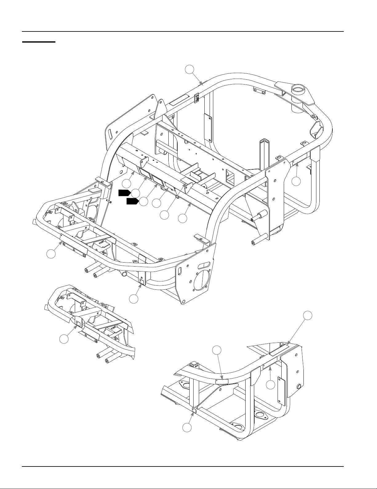
Frame
1
3
2
4
1
4
5
6
7
9
8
8
10
2
11
2
8
VIEWED FROM
REAR OF FRAME
2-2 114443_1011
Page 9

Frame
1. Serial Number plate. In the event the serial number tag becomes
2. EPA compliance plate.
INDEX NO. PART NO. QTY. DESCRIPTION
1 551011 1 FRAME, 1500 (WITH DECALS)
2 602814 2 1500 TRIPLEX DECAL
3 602308 1 CUT HEIGHT DECAL
4 N/A 2 TURF PRODUCTS SERIAL NO. PLATE
5 602926 1 SEAT LATCH DECAL
6 601968 1 HYDRAULIC PRESSURE DECAL
7 602919 1 SAFETY DECAL
8 602921 3 JACKING/LIFTING DECAL
9 602261 1 HUSTLER LOGO DECAL
10 602041 1 HOT DECAL
11 603466 1 DECAL, SAFETY ENG COVER
NOTES:
damaged or illegible, please contact your dealer to order a replacement.
114443_1011 2-3
Page 10
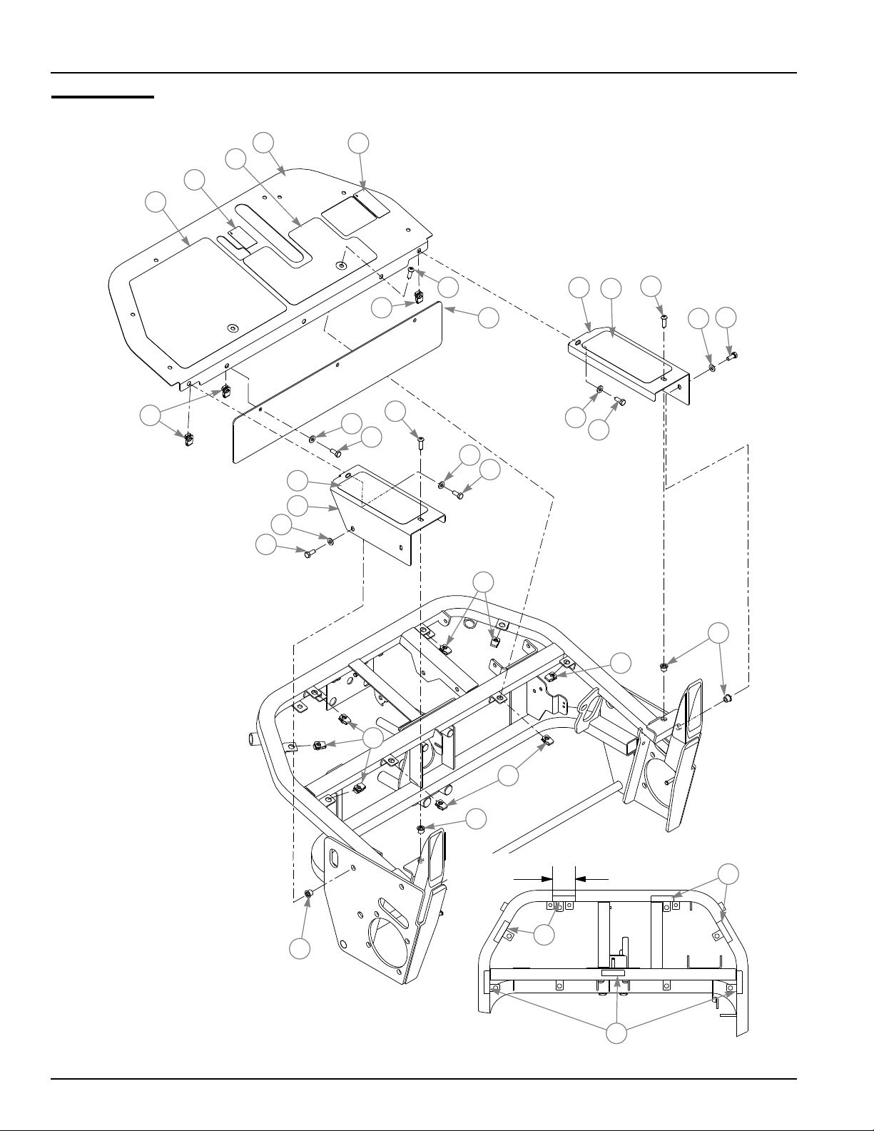
Footrest
1
3
4
5
9
12
13
7
14
2
8
9
8
7
14
10
7
14
11
7
12
14
8
14
7
9
6
9
9
9
6
3" TYP
15
6
15
15
2-4 114443_1011
Page 11

Footrest
INDEX NO. PART NO. QTY. DESCRIPTION
1 550986 1 FLOOR PLATE (WITH TREADS & DECALS)
2 602920 1 FWD-REV DECAL
3 112852 1 FOOT PAN STEP TREAD
4 602915 1 PARK BRAKE DECAL
5 603364 1 LEFT STEP TREAD
6 808485 6 RIVET NUT, 5/16-18 THREAD
7 768523 9 FW .343 X .687 X .051/.080H
8 602727 10 CS .312-18 X 1.0 BHSK ZNYC
9 601069 13 CN .312-18 X .200 MAX THK
10 114392 1 FLOOR PLATE EXTENSION
11 550984 1 RS FLOOR COVER (WITH TREAD)
12 112851 2 STEP TREAD, COVER
13 550985 1 LS FLOOR COVER (WITH TREAD)
14 034280 9 CS .312-18 X .750 HX G5
15 033035 21" WEATHERSTRIP .12 X .75
NOTES:
114443_1011 2-5
Page 12

Basket
1
3
2
4
5
2-6 114443_1011
Page 13

Basket
ITEM NO. PART NO. QTY. DESCRIPTION
1 602779 1 BASKET
2 114139 1 STIFFENER
3 601098 5 CB 10-24 X .500 ZYNC
4 704932 5 FW .219 X .500 X .048 ZN
5 059832 5 NT #10-24 HX NL ZN
NOTES:
114443_1011 2-7
Page 14

2-8 114443_1011
Page 15

Section 3
Steering Wheel Support . . . . . . . . . . . . . . . . . . . . . . . . . . . . . . . . . . 3-2
Drive Linkage. . . . . . . . . . . . . . . . . . . . . . . . . . . . . . . . . . . . . . . . . . . 3-4
Rear Steering Fork . . . . . . . . . . . . . . . . . . . . . . . . . . . . . . . . . . . . . 3-10
Brake . . . . . . . . . . . . . . . . . . . . . . . . . . . . . . . . . . . . . . . . . . . . . . . . 3-12
114443_1011 3-1
Page 16
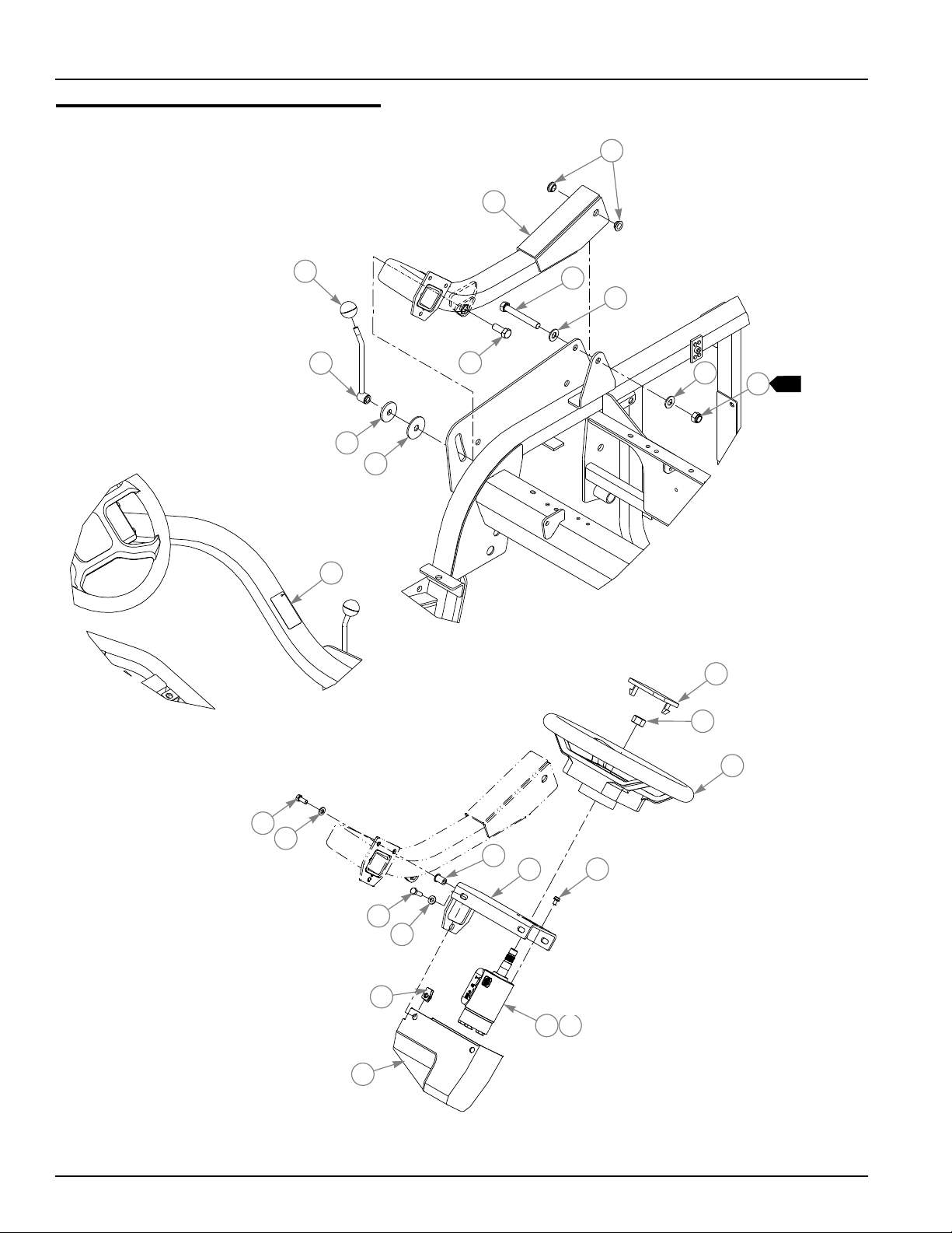
Steering Wheel Support
2
1
7
8
9
10
3
11
4
5
5
12
13
1
6
15
16
21
18
20
16
14
17
19
23
3-2 114443_1011
22
24
Page 17

Steering Wheel Support
INDEX NO. PART NO. QTY. DESCRIPTION
1 112050 1 STEERING TUBE
2 768259 2 BUSHING
3 602924 1 STEERING DECAL
4 068023 1 CS .500-13 X 3.750 HX G8
5 767962 2 FW .531 X 1.063 X .090 SAE
6 781567 1 NT .500-13 HX G8 ZY NL
7 601059 1 KNOB
8 112057 1 PIVOT HANDLE
9 078386 1 FW .510 X 1.750 X .18 ZNYC
10 263517 1 BEARING DISC
11 705954 1 CS .500-13 X 1.250 HX G5 ZN
12 602899 1 STEERING WHEEL CAP
13 021634 1 NT .625-18 HX PN
14 602426 1 STEERING WHEEL
15 034280 3 CS .312-18 X .750 HX G5
16 768523 7 FW .343 X .687 X .051/.080H
17 808485 3 RIVET NUT, 5/16-18 THREAD
18 036236 4 CS .312-18X1.000 HX G5
19 112059 1 BRACKET
20 601069 4 CN .312-18X.200 MAX THK
21 602569 1 STEERING COVER
22 739144 4 CS M 6-1.0 X 12 10.9 HX
23 602420 1 STEERING UNIT
24 603416 1 SEAL KIT–STEERING UNIT
NOTES:
1. Do not torque nut; it should be snug but allow the steering tube to pivot
freely.
114443_1011 3-3
Page 18
Drive Linkage
3
4
1
2
VIEWED FROM
REAR OF MOWER
1
1
21
22
16
18
19
20
15
17
13
14
12
7
8
10
9
11
16
12
20
23
24
17
5
6
9
25
20
19
3-4 114443_1011
26
20
27
17
24
Page 19

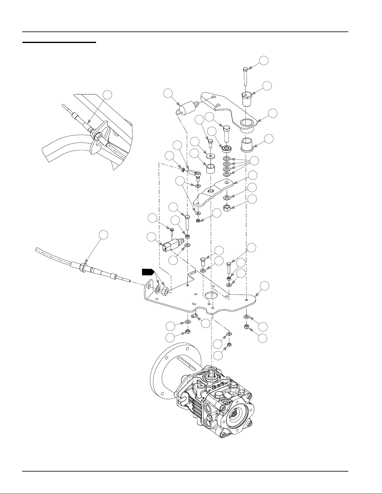
Drive Linkage
INDEX NO. PART NO. QTY. DESCRIPTION
1 602610 1 CABLE, PUSH/PULL 2"STRK
2 036384 1 SPRING 1/4 COIL PL 1.23
3 038828 1 CS .312-18 X 2.250 HX G5
4 112497 1 PIVOT CAM STUD
5 112496 1 CENTERING LEVER
6 603262 1 BUSHING, 1.00 I.D.
7 017616 1 CS .500-13 X 1.750 HX G5
8 602631 1 BEARING
9 718288 5 FW .516 X .875 X .09 ZNYC
10 112493 1 CONTROL LEVER ARM
11 008193 1 NT .500-13 HX G5 ZNYC
12 028035 5 CS M 8-1.25 X 20 HX G8.8
13 712927 1 FW .344 X 1.00 X.12 HRD Z
14 602867 1 SPACER, 1.00 OD X .109
15 602630 2 ROD END W STUD 1/4-28
16 058842 4 NT .250-28 HX JAM ZNYC
17 768515 11 FW .281 X .625 X .051/.080H
18 050161 2 CS .312-18 X 1.750 HX G5
19 034272 9 NT .312-18 HX G5 ZNYC
20 768523 16 FW .343 X .687 X .051/.080H
21 063198 2 CS 10-24 X .750 HXFLK ZN
22 602538 1 SWITCH PLUNGER, NC/NO
23 704916 1 CS .250-20 X 1.250 HX G5
24 024927 5 NT .250-20 HX GR.5 ZNYC
25 112492 1 BASEPLATE
26 601822 1 NUT PLATE, .420 CENTERS
27 058776 1 NT .312-18 HXZY NL
NOTES:
1. Part of cable.
114443_1011 3-5
Page 20
Drive Linkage
28
29
30
VIEWED FROM
REAR OF MOWER
18
19
20
20
31
32
20
19
24
15
17
20
16
37
35
19
VIEWED FROM
UNDERNEATH
33
36
34
33
20
31
16
17
3-6 114443_1011
Page 21

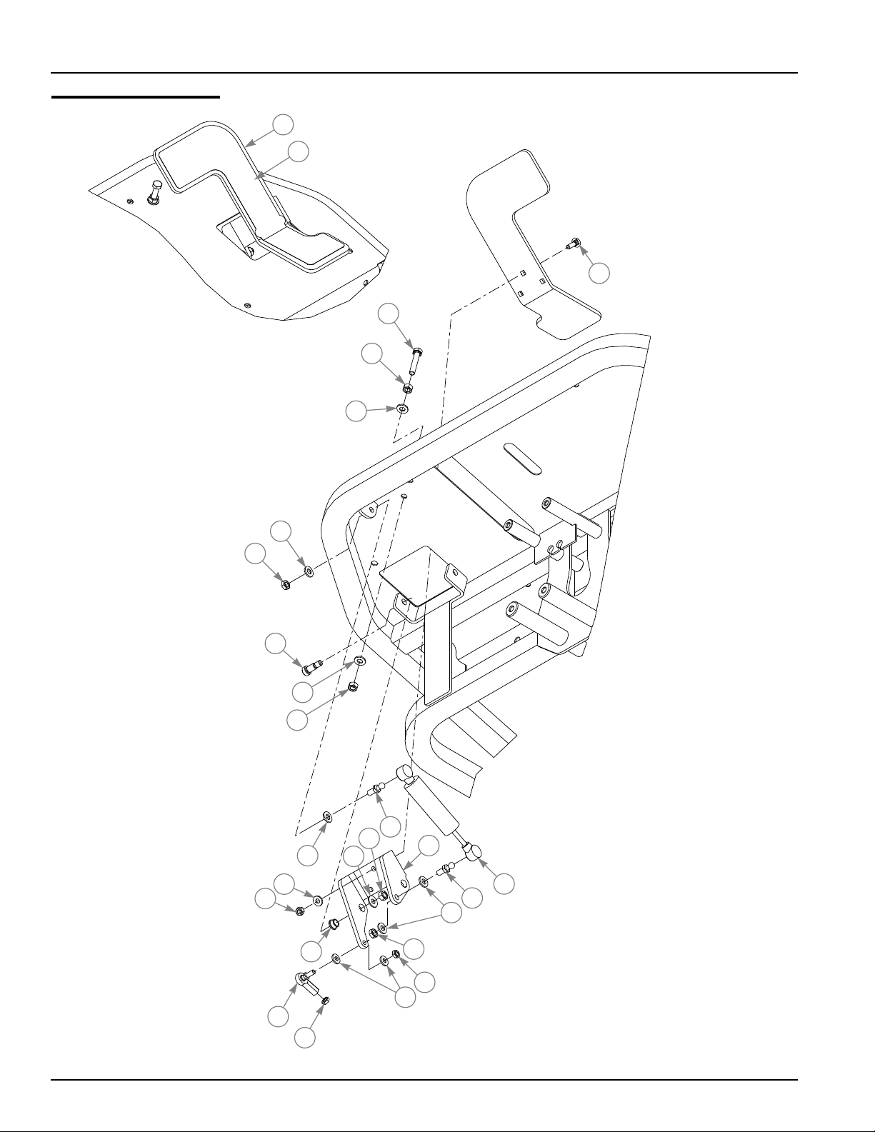
Drive Linkage
INDEX NO. PART NO. QTY. DESCRIPTION
28 551017 1 FWD/REV PEDAL (W/ TREAD)
29 602706 1 STEP TREAD
30 056325 3 CB .250-20 X 1.000 FUL Z
31 706143 2 NT .312-18 HX JAM GR5 ZY
32 722678 2 SB .375 X .62SH .312-18 T
33 781922 2 BALL STUD
34 602667 1 STEERING DAMPER
35 713685 2 FW .312 X .75 X .06 ZNYC
36 114303 1 PIVOT BRACKET
37 765339 3 BUSHING
NOTES:
114443_1011 3-7
Page 22
Drive Linkage
19
20
20
19
19
38
20
37
39
46
40
43
41
42
44
45
17
47
48
3-8 114443_1011
Page 23

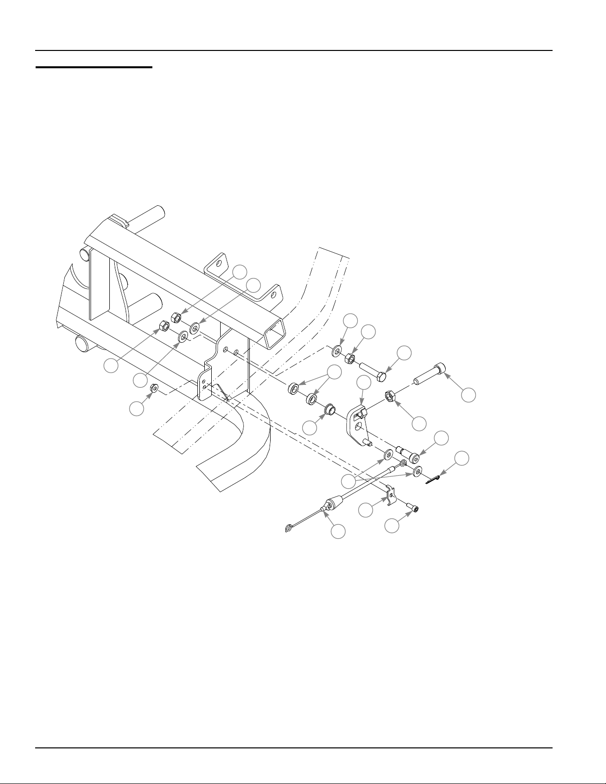
Drive Linkage
INDEX NO. PART NO. QTY. DESCRIPTION
38 016774 1 NT #10-24 HXFLK ZN
39 601839 2 PIVOT SPACER BUSHING
40 052837 1 CS .312-18 X 1.500 HX G5
41 603417 1 CS .375-16 X 1.75 SH ZN
42 706168 1 NT .375-16 HX JAM GR5 Z
43 114284 1 PIVOT
44 032581 1 SB .375 X .750 SH.312-18
45 017236 1 CP .093D X .750 LG HML Z
46 603321 1 CABLE, MOW STOP
47 011841 1 CONDUIT CLIP
48 794495 1 CS 10-24 X .500 SKTHD Z
NOTES:
114443_1011 3-9
Page 24
Rear Steering Fork
1
5
6
12
6
2
3
4
7
4
29
13
14
6
6
28
32
31
26
15
25
23
30
27
24
17
18
8
9
20
22
10
11
16
19
20
21
3-10 114443_1011
Page 25

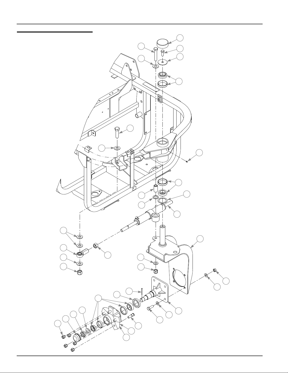
Rear Steering Fork
INDEX NO. PART NO. QTY. DESCRIPTION
1 602726 1 VINYL CAP
2 705954 1 CS .500-13 X 1.250 HX G5 ZN
3 602668 1 FW .531 X 2.5 X .134
4 602425 2 ROLLER BEARING
5 047704 1 CS .625-11 X 3.500 HX G5
6 025296 5 FW .760 X 1.625 X .08 ZNYC
7 015495 1 GREASE FITTING STRAIGHT
8 115157 1 BUSHING, STEER CYLINDER
9 045765 1 FW 1.030 X 1.500 X .134 ZN
10 115839 1 GREASE SHIELD
11 602417 1 STEERING CYLINDER
12 016725 1 CS .750-10 X 2.500 HX ZNY
13 602721 1 ROD END
14 061101 1 NT .750-10 HXZY NL
15 036855 1 NT .750-16 HX ZNYC
16 111976 1 CASTER FORK
17 728030 1 FW .656 X 1.312 X .090 ZNY
18 058768 1 NT .625-11 HXZY NY
19 008193 4 NT .500-13 HX G5 ZNYC
20 767962 8 FW .531 X 1.063 X .090 SAE
21 112138 1 SPINDLE
22 074252 4 CS .500-13 X 1.500 HX G5
23 602526 1 SPINDLE HUB
24 602533 5 WHEEL STUD
25 602527 1 SEAL
26 603410 1 HUB BEARING, RACE KIT (INCLUDES SEAL)
27 602532 1 HUB
28 602529 1 DUST CAP
29 061077 5 LUG NUT
30 602525 1 COTTER PIN
31 602524 1 WASHER
32 602523 1 SHAFT NUT
NOTES:
114443_1011 3-11
Page 26
Brake
1
2
1
2
6
7
8
10
5
9
4
5
11
12
4
5
6
4
3
3
3-12 114443_1011
Page 27

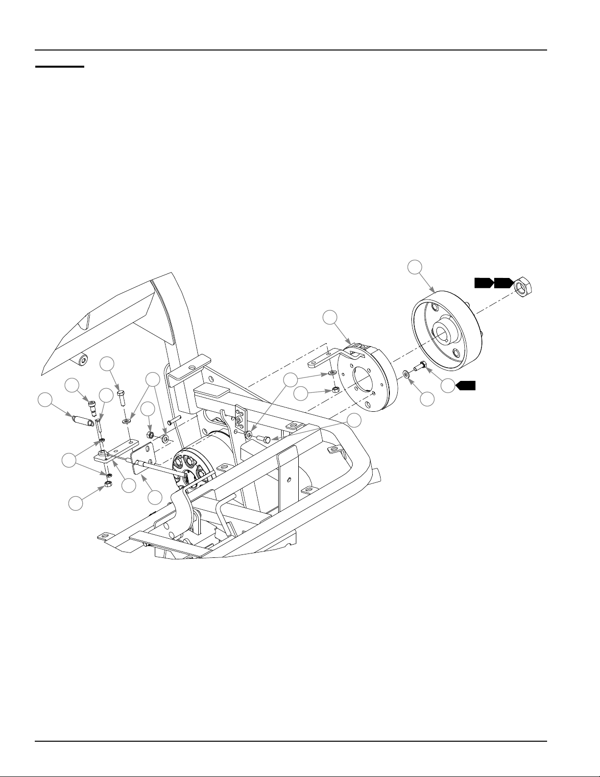
Brake
1. Included with wheel motor.
2. Torque to 220–240 ft-lbs.
INDEX NO. PART NO. QTY. DESCRIPTION
1 602384 2 HUB ASSY (WITH STUDS)
2 602383 2 BRAKE ASSY
3 064014 8 CS .312-18 X .875 HX G5 ZN
4 768523 24 FW .343 X .687 X .051/.080H
5 034272 10 NT .312-18 HX G5 ZNYC
6 036236 8 CS .312-18 X 1.000 HX G5
7 063297 2 SB .375 X .500 SH .312-1
8 018960 3 SPRING
9 715599 2 CS 10-24X1.000 HX G5 ZN
10 035626 4 NT #10-24 HX ZN
11 114026 2 BRAKE ARM
12 114193 2 CONDUIT HOLD DOWN
NOTES:
3. Torque to 17 ft-lbs.
114443_1011 3-13
Page 28
Brake
13
14
16
15
3-14 114443_1011
Page 29

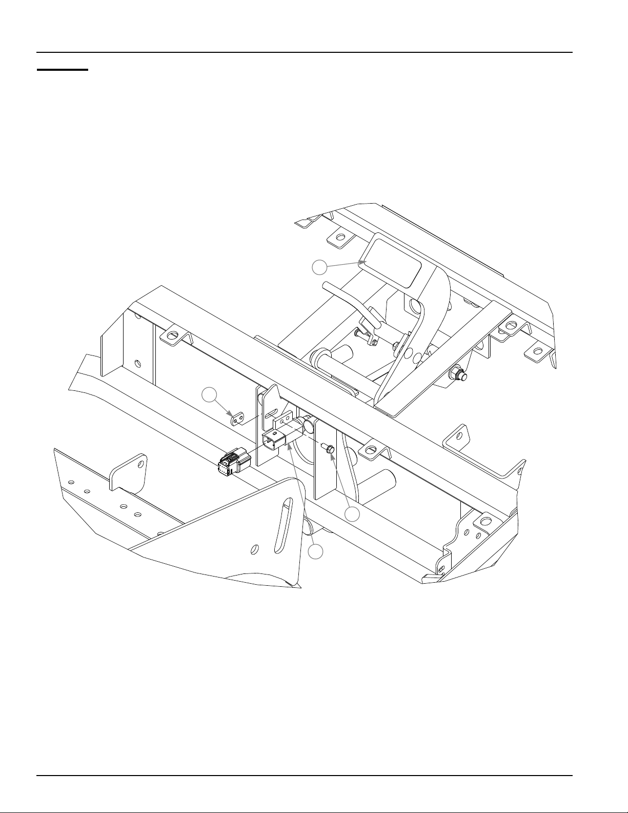
Brake
INDEX NO. PART NO. QTY. DESCRIPTION
13 112853 1 BRAKE STEP TREAD
14 601822 1 NUT PLATE, .420 CENTERS
15 602538 1 SWITCH PLUNGER, NC/NO
16 060731 2 CS 10-24 X .500 HXFLK ZN
NOTES:
114443_1011 3-15
Page 30
Brake
17
24
31
22
18
20
19
21
22
23
25
8
31
25
32
25
28
31
26
27
25
29
30
3-16 114443_1011
Page 31

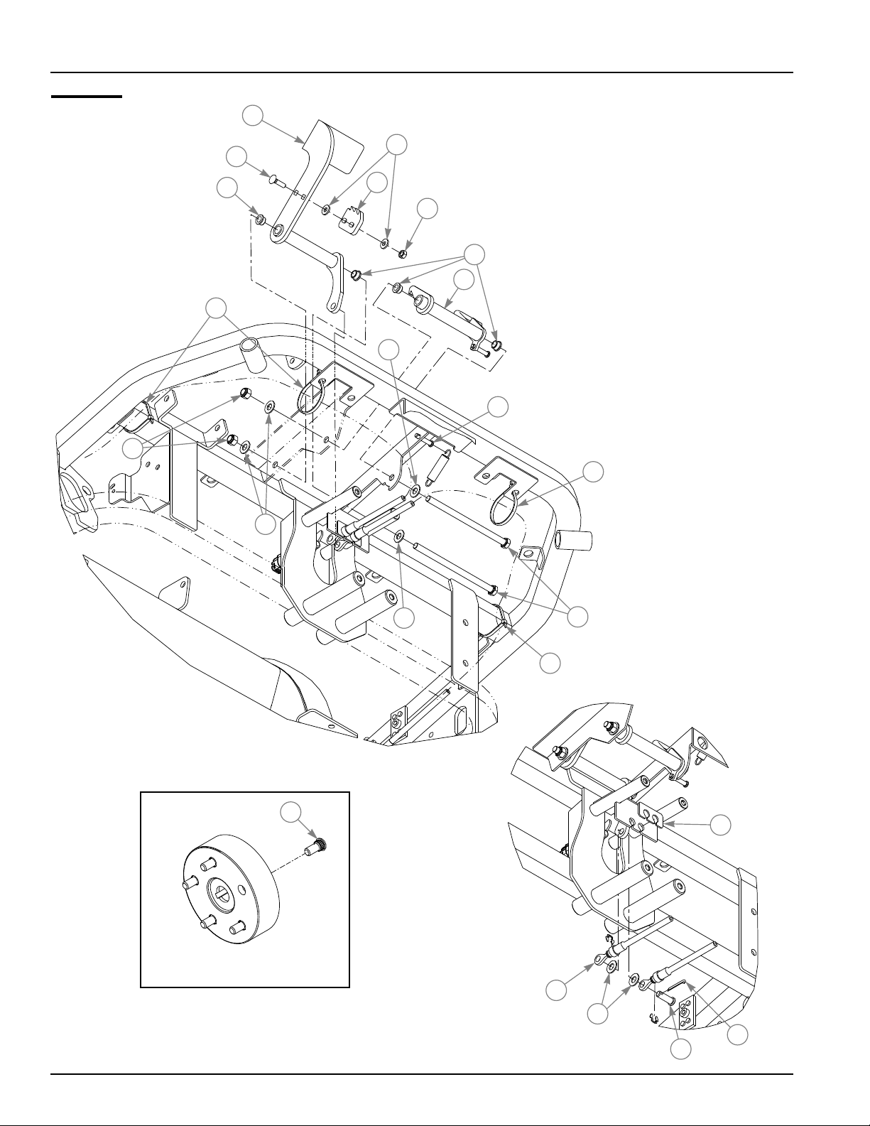
Brake
INDEX NO. PART NO. QTY. DESCRIPTION
17 551016 1 BRAKE PEDAL
18 056325 2 CB .250-20 X 1.000 FUL Z
19 112799 1 LATCH PLATE
20 768515 4 FW .281 X .625 X .051/.080H
21 024927 2 NT .250-20 HX GR.5 ZNYC
22 765339 4 BUSHING
23 112794 1 LATCH
24 086660 2 NT .375-16 HXZY NL
25 767954 6 FW .406 X .812 X .060 SAE
26 114033 1 CABLE SPACER
27 603202 2 BRAKE CABLE
28 602695 2 CS .375-16 X 6.50 G5 ZNYC
29 017244 1 CP .125D X 1.000 LG HML Z
30 076745 1 CE .375 X 1.125 .15 X .968
31 000430 4 WIRE TIE, SMALL/LONG
32 601085 1 STUD, WHEEL LUG 1/2-20
NOTES:
114443_1011 3-17
Page 32

3-18 114443_1011
Page 33

Section 4
Wheel & Tire . . . . . . . . . . . . . . . . . . . . . . . . . . . . . . . . . . . . . . . . . . . 4-2
Wheel & Tire Breakdown. . . . . . . . . . . . . . . . . . . . . . . . . . . . . . . . . . 4-4
114443_1011 4-1
Page 34

Wheel & Tire
2
2
1
1
2
3
1
1
4-2 114443_1011
Page 35

Wheel & Tire
INDEX NO. PART NO. QTY. DESCRIPTION
1. Inflate tire to 8–12 psi.
2. Torque to 65–75 ft-lbs.
3. Wheel nuts for rear tire (qty. 5) come with p/n 602526 (wheel hub).
1 602463 3 WHEEL & TIRE ASSY 20 X 10-10
2 061077 15 WHEEL NUT
NOTES:
114443_1011 4-3
Page 36

Wheel & Tire Breakdown
602463
1
2
INDEX NO. PART NO. QTY. DESCRIPTION
1 602466 1 TIRE, 20 X 10-10
2 602467 1 WHEEL, 10 X 8
3 019521 1 TIRE VALVE
3
4-4 114443_1011
Page 37

Section 5
Battery . . . . . . . . . . . . . . . . . . . . . . . . . . . . . . . . . . . . . . . . . . . . . . . . 5-2
Instrument Panel . . . . . . . . . . . . . . . . . . . . . . . . . . . . . . . . . . . . . . . . 5-4
Glove Box Breakdown. . . . . . . . . . . . . . . . . . . . . . . . . . . . . . . . . . . . 5-8
114443_1011 5-1
Page 38

Battery
1
NEGATIVE
CABLE (BLACK)
1
BATTERY
POSITIVE
CABLE (RED)
2
3
5
6
54
5
7
5
4
8
5-2 114443_1011
Page 39

Battery
1. When performing service on mower, disconnect battery ground cable
and do not reconnect to battery until engine is ready to be started. See
Operator’s Manual.
2. Route battery cables as shown in Fig. 1.
INDEX NO. PART NO. QTY DESCRIPTION
1 769356 2 CS .250-20 X 4.25 HX G5 Z
2 768515 2 FW .281 X .625 X .051/.080H
3 348417 1 BATTERY CLAMP STRAP
4 055939 2 CS .250-20 X .750 HX G5
5 029868 4 LW .250 INT-EXT TOOTH Z
6 024927 2 NT .250-20 HX GR.5 ZNYC
7 771428 1 BATTERY CBL BOOT-RED
8 601982 2 CN .250-20 X .150 MAX THK
NOTES:
POSITIVE
BATTERY
CABLE
NEGATIVE
BATTERY
CABLE
FIG. 1
114443_1011 5-3
Page 40

Instrument Panel
1
14
2
1
11
3
3
6
7
12
6
7
4
5
8
9
12
13
10
5
16
15
5
10
15
5
17
2
3
5
4
5
4
5-4 114443_1011
Page 41

Instrument Panel
INDEX NO. PART NO. QTY. DESCRIPTION
1 112661 1 INSTRUMENT PANEL
2 603323 1 INSTRUMENT PANEL DECAL
3 114884 1 INSTRUMENT PANEL PLATE
4 064006 5 CS .312-18 X .625 HX G5
5 768523 12 FW .343 X .687 X .051/.080H
6 064329 10 CS .250-20 X .625 HX G5
7 768515 28 FW .281 X .625 X .051/.080H
8 602696 1 LIFT/LOWER DECAL
9 602923 1 CHOKE DECAL
10 034280 4 CS .312-18 X .750 HX G5
11 602844 1 GLOVE BOX
12 808477 10 1/4-20 THREAD NUTSERT
13 112665 1 SWITCH BOX
14 000331 2 WIRE TIE, SMALL/SHORT
15 808485 4 RIVET NUT, 5/16-18 THREAD
16 112670 1 INSTRUMENT PANEL
17 034272 3 NT .312-18 HX G5 ZNYC
114279 1 INSTRUMENT PANEL PLATE
NOTES:
1. When ordering the instrument panel, also order (1) 114884 or 114279,
(4) 808477, (4) 768515 and (4) 064329.
2. Mowers with serial numbers prior to 11080000 require 114279.
3. Mowers with serial numbers 11080000 and higher require 114884.
114443_1011 5-5
Page 42

Instrument Panel
44
31
32
45
6
46
7
47
12
34
7
34
26
60
7
27
28
18
48
33
31
7
19
30
39
45
17
57
49
20
21
34
50
5
49
22
25
23
24
26
4
18
29
27
28
34
7
35
43
36
55
57
34
37
7
38
58
7
59
7
7
34
34
41
46
56
31
40
42
51
4
53
52
16
YEL/GREY
BLK
ORG
YEL/BLK
54
7
4
ORG/RED
34
BLK
ORG
ORG/PUR
BLK
ORG/PUR
5-6 114443_1011
Page 43

Instrument Panel
INDEX NO. PART NO. QTY. DESCRIPTION
18 043299 2 KNOB
19 602646 1 RUBBER BELLOW
20 712257 3 RED INDICATOR LIGHT
21 769166 1 HOUR METER
22 601116 1 LIGHT SWITCH KIT
23 785808 1 KEY ASSEMBLY
24 045898 1 IGNITION SWITCH
25 601503 2 CB .250-20 X .625 ZNYC
26 601098 4 CB 10-24 X .500 ZYNC
27 704932 4 FW .219 X .500 X .048 ZNYC
28 059832 4 NT #10-24 HX NL ZN
29 778365 1 THROTTLE CABLE
30 112738 1 RETAINING RING
31 765339 3 BUSHING
32 602654 1 SPRING
33 112701 1 HANDLE
34 024927 14 NT .250-20 HX GR.5 ZNYC
35 114286 1 MOUNT PLATE
36 056119 2 CS .250-20 X 1.000 SH BO
37 114287 1 MOW SPEED LEVER
38 017236 1 CP .093D X .750 LG HML Z
39 705145 1 CS .250-20 X 1.750 HX G5
40 076422 1 FW .406 X 1.000 X .06 ZNYC
41 601507 1 FW .406 X 1.000 X .06 NYLON
42 063297 1 SB .375 X .500 SH .312-1
43 008581 1 CS .250-20 X 1.500 HX G5
44 705731 1 CS .375-16 X 2.750 G5 ZNY
45 767954 2 FW .406 X .812 X .060 SAE
46 602669 6 MS #4-40 X 3/4 PHIL PH
47 112669 1 LIFT LEVER BASE
48 602720 1 LIFT/LOWER WIRE HARNESS
49 602222 6 NT #4-40 HX ZN
50 086660 1 NT .375-16 HXZY NL
51 786657 1 CHOKE CABLE
52 794784 2 CB .250-20 X .75 FUL ZN
53 602409 1 CONTROLLER
54 602410 1 WIRE HARNESS
55 603352 1 SPRING, EXT 2.05" X .56"
56 603328 1 WIRE HARNESS, MOW STOP SWITCH
57 603411 2 NYLON SPACER .255 X .374 X .511
58 017079 2 FW .250 X .560 X .04 SAE Z
59 075408 1 FW .402 X .689 X .032 ZNYC
60 056077 2 CS .250-20 X 1.000 HX G5
NOTES:
4. Part of wiring harness.
114443_1011 5-7
Page 44

Glove Box Breakdown
2
3
1
INDEX NO. PART NO. QTY. DESCRIPTION
1 602846 1 GLOVE BOX BASE
2 602845 1 GLOVE BOX LID
3 603464 1 GLOVE BOX LATCH W/ MOUNTING HARDWARE
5-8 114443_1011
Page 45

Section 6
Engine & Pump . . . . . . . . . . . . . . . . . . . . . . . . . . . . . . . . . . . . . . . . . 6-2
Engine Service Parts. . . . . . . . . . . . . . . . . . . . . . . . . . . . . . . . . . . . . 6-6
Fuel System. . . . . . . . . . . . . . . . . . . . . . . . . . . . . . . . . . . . . . . . . . . . 6-8
114443_1011 6-1
Page 46

Engine & Pump
1
9
24 25
RED
24
25
24
25
28
30
32
2
24
6
25
3
BLK
1
BLK
4
39
5
7
1
YEL
3
3
3
ORG
1
PUR
3
12
14
15
16
RED
26
27
15
14
29
1
RED
25
15
18
19
17
9
13
1
10
11
15
3
8
14
15
3
31
1
BLK
33
22
36
3
20
21
23
1 2
34
35
3
22
37
38
6-2 114443_1011
Page 47

Engine & Pump
INDEX NO. PART NO. QTY. DESCRIPTION
1 N/A 1 ENGINE 18HP BRIGGS
2 064345 4 CS .312-18 X 2.000 HX G5
3 768523 24 FW .343 X .687 X .051/.080H
4 786640 1 BATTERY CABLE, NEGATIVE
5 029876 1 LW .312 INT-EXT TOOTH
6 114265 1 SHIELD
7 601069 4 CN .312-18 X .200 MAX THK
8 034280 4 CS .312-18 X .750 HX G5
9 000331 2 WIRE TIE, SMALL/SHORT
10 603365 1 MUFFLER
11 794180 1 CLAMP, 1.125"
12 602464 1 MANIFOLD
13 796672 1 OIL DRAIN VALVE, 3/8-18
14 054502 7 NT .375-16 HX GRD 5 ZNY
15 767954 13 FW .406 X .812 X .060 SAE
16 036244 2 CS .375-16 X 1.000 HX G5
17 113438 1 MUFFLER MNT W/A
18 113627 1 MUFFLER MOUNT SPACER
19 111929 1 ENGINE PLATE
20 052860 2 CS .375-16 X 1.25 HX G5 ZN
21 783829 2 FW .460 X 1.750 X .250 ZN
22 034272 10 NT .312-18 HX G5 ZNYC
23 602733 3 ISOLATION MOUNT
24 024927 6 NT .250-20 HX GR.5 ZNYC
25 768515 8 FW .281 X .625 X .051/.080H
26 785063 1 BATTERY CABLE, POSITIVE
27 771428 1 RED BATTERY CABLE BOOT
28 792762 1 BATTERY CABLE, POSITIVE
29 044255 1 NT #10-32 HX ZN
30 030817 1 STARTER SOLENOID
31 055939 2 CS .250-20 X .750 HX G5
32 043570 1 HOSE CLIP
33 063198
34 704932 1 FW .219 X .500 X .048 ZNYC
35 059832 1 NT #10-24 HX NL ZN
36 036236 6 CS .312-18 X 1.000 HX G5
37 603149 3 SNUB WASHER
38 016428 3 CS .375-16 X 2.50 HX GR5
39 794784 2 CB .250-20 X .75 FUL ZN
1 CS 10-24 X .750 HXFLK ZN
NOTES:
1. Part of wire harness.
2. Contains a 20A fuse.
3. Part of engine.
114443_1011 6-3
Page 48

Engine & Pump
14
15
55
51
52
15
53
54
50
47
45
46
49
44
48
43
40
42
41
40
36
3
23
3
37 22
38
6-4 114443_1011
Page 49

Engine & Pump
INDEX NO. PART NO. QTY. DESCRIPTION
40 712372 2 KEY 1/4 SQ X 0.66 LG
41 602544 1 COUPLER HALF 1"
42 602546 1 COUPLER FLEX JOINT
43 602545 1 COUPLER HALF .875"
44 017012 4 LW .375 MED SPRING ZNYC
45 080655 4 CS .375-16 X 1.500 HX G5
46 602441 1 ENGINE/PUMP ADAPTER
47 602259 1 PUMP
48 767962 2 FW .531 X 1.063 X .090 SAE
49 017616 2 CS .500-13 X 1.750 HX G5
50 603054 1 GASKET
51 602423 1 TANDEM GEAR PUMP
52 113383 1 PUMP SUPPORT
53 038836 2 CS M10-1.50 X 25 HX ZN
54 603362 1 SEAL KIT–PUMP
55 603405 1 SEAL KIT–TANDEM GEAR PUMP
NOTES:
114443_1011 6-5
Page 50

Engine Service Parts
1
2
3
INDEX NO. PART NO. QTY. DESCRIPTION
1 603194 1 AIR CLEANER ELEMENT
2 603195 1 SAFETY FILTER ELEMENT
3 603196 1 ENGINE OIL FILTER
6-6 114443_1011
Page 51

This page intentionally left blank.
114443_1011 6-7
Page 52

Fuel System
2
1
5
3
1
4
5
6
6
5
7
8
2
6
3
6-8 114443_1011
Page 53

Fuel System
INDEX NO. PART NO. QTY. DESCRIPTION
1 602980 2 3.0" CUSHIONED CLAMP
2 767954 2 FW .406 X .812 X .060 SAE
3 055822 5 CS .375-16 X .750 HX G5
4 602982 1 CARBON CANISTER, 9 GAL.
5 000323 6 HOSE CLAMP
6 015818 69" 1/4" FUEL LINE
7 603221 1 FTG, -4BARB / -6BARB STR
8 603224 1 SPRING CLAMP
NOTES:
FUEL & VAPOR LINE LENGTHS
1
2
3
28" TANK TO CANISTER (VAPOR)
20" TANK TO FUEL FILTER (FUEL)
21" CANISTER TO ENGINE (VAPOR)
114443_1011 6-9
Page 54

Fuel System
12
13
10
14
11
15
VIEWED FROM
UNDERNEATH
28
18
16
17
19
A
18
C
20
18
21
18
23
24
22
A
18
9
27
B
31
30
29
25
3
6-10 114443_1011
Page 55

Fuel System
INDEX NO. PART NO. QTY. DESCRIPTION
9 602702 1 FUEL TANK
10 602703 1 REAR COVER
11 602916 1 RATCHETING GAS CAP, 3.5"
12 714998 2 MS #10-24 X .625 HX ZN
13 773523 1 KEEPER, FLEXDRAW #37-25
14 704932 2 FW .219 X .500 X .048 ZNYC
15 059832 2 NT #10-24 HX NL ZN
16 773416 1 FLEX DRAW LATCH
17 601089 2 RIVET .188 DIA BLK HD
18 033001 3.25’ TRIM
19 601069 2 CN .312-18 X .200 MAX THK
20 113273 1 COVER LATCH PLATE
21 768523 4 FW .343 X .687 X .051/.080H
22 036236 4 CS .312-18 X 1.000 HX G5
23 808485 2 RIVET NUT, 5/16-18 THREAD
24 113275 1 REAR COVER MOUNT
25 712919 3 FW .406 X 1.00 X.12 HRD Z
26 000331 1 WIRE TIE, SMALL/SHORT
27 115684 1 FUEL TANK SUPPORT
28 603161 1 VACUUM BREAKER FILTER
29 603158 1 ROLLOVER VALVE & GROMMET
30 785295 1 SUCTION HOSE GROMMET
31 601527 1 SUCTION HOSE 19.5
NOTES:
CUT TRIM LENGTHS
A
3" TWO (2) PIECES
10" TWO (2) PIECES
B
C
13" ONE (1) PIECE
114443_1011 6-11
Page 56

6-12 114443_1011
Page 57

Section 7
Hydraulic Reservoir . . . . . . . . . . . . . . . . . . . . . . . . . . . . . . . . . . . . . . 7-2
Hydraulic—Oil Cooler . . . . . . . . . . . . . . . . . . . . . . . . . . . . . . . . . . . . 7-6
Hydraulic—Oil Cooler Hoses. . . . . . . . . . . . . . . . . . . . . . . . . . . . . . . 7-8
Hydraulic Valve Block . . . . . . . . . . . . . . . . . . . . . . . . . . . . . . . . . . . 7-10
Traction Drive . . . . . . . . . . . . . . . . . . . . . . . . . . . . . . . . . . . . . . . . . 7-16
Hydraulic—Steering. . . . . . . . . . . . . . . . . . . . . . . . . . . . . . . . . . . . . 7-20
Hydraulic Reel Drive . . . . . . . . . . . . . . . . . . . . . . . . . . . . . . . . . . . . 7-22
Hydraulic Reel Lift . . . . . . . . . . . . . . . . . . . . . . . . . . . . . . . . . . . . . . 7-24
114443_1011 7-1
Page 58

Hydraulic Reservoir
1
3
4
5
2
6
1
7
2
1
7
1
8
6
11
12
13
13
1
9
10
6
7-2 114443_1011
Page 59

Hydraulic Reservoir
INDEX NO. PART NO. QTY. DESCRIPTION
1 112383 1 HYDRAULIC RESERVOIR
2 781658 2 FTG, -8 MORB/HEX PLUG
3 603359 1 FTG, 3/8 NPT X 1/4 NPT STR
4 602618 1 HOSE ASSY, FILTER-RES
5 602616 1 HOSE ASSY, REEL CASE
6 781534 2 FTG, STR-8 MORB/-8MS
7 602573 1 FTG, TEE 8 MORB/6MSL
8 602638 1 HOSE ASSY, HST CASE
9 602756 1 FTG, 12 MORB/12BT 90
10 602649 1 HOSE, SUCTION RES-GEAR
11 783985 1 FTG, STR ORB-BEADED
12 602648 1 STRAINER, IN TANK - 3/4"
13 700484 2 HOSE CLAMP
1. Orient as shown.
NOTES:
114443_1011 7-3
Page 60

Hydraulic Reservoir
17
14
15
21
14
15
15
16
22
18
15
16
19
23
15
20
24
16
15
14
14
15
7-4 114443_1011
Page 61

Hydraulic Reservoir
INDEX NO. PART NO. QTY. DESCRIPTION
14 034280 6 CS .312-18 X .750 HX G5
15 768523 14 FW .343 X .687 X .051/.080H
16 034272 6 NT .312-18 HX G5 ZNYC
17 602929 1 BREATHER CAP 1IN NPT
18 601069 2 CN .312-18 X .200 MAX THK
19 114199 1 TANK ADJUSTER
20 036236 2 CS .312-18 X 1.000 HX G5
21 603322 1 SIGHT GLASS
22 114252 1 HEAT SHIELD
23 043570 2 LOOP CLAMP
24 114428 1 TEMPERATURE SWITCH ASSY
NOTES:
114443_1011 7-5
Page 62

Hydraulic—Oil Cooler
1
2
3
11
5
7
10
7
8
9
6
12
17
2
6
4
15
14
2
4
7
13
1
2
16
7-6 114443_1011
Page 63

Hydraulic—Oil Cooler
INDEX NO. PART NO. QTY. DESCRIPTION
1 034280 10 CS .312-18 X .750 HX G5
2 768523 16 FW .343 X .687 X .051/.080H
3 112181 1 SUPPORT ANGLE
4 601069 6 CN .312-18 X .200 MAX THK
5 112174 1 OIL COOLER SHROUD
6 034272 6 NT .312-18 HX G5 ZNYC
7 713198 4' SEAL 3/8 X 3/4
8 602564 1 OIL COOLER
9 033035 3.25' WEATHERSTRIP .12 X .75
10 113561 1 OIL COOLER SCREEN
11 113557 1 FRONT PANEL OIL COOLER
12 079210 2 FW .344 X 1.00 X .06 ZNYC
13 602620 1 GROMMET
14 602619 2 BUSHING
15 112618 2 SPACER TUBE
16 052837 2 CS .312-18 X 1.500 HX G5
17 781658 1 FTG, -8 MORB/HEX PLUG
NOTES:
114443_1011 7-7
Page 64

Hydraulic—Oil Cooler Hoses
1
27
28
19
26
29
26
25
20
18
2
4
24
21
23
31
22
30
7-8 114443_1011
Page 65

Hydraulic—Oil Cooler Hoses
INDEX NO. PART NO. QTY. DESCRIPTION
18 114404 1 BYPASS MOUNT PLATE
19 601429 1 UBOLT .250-20 X 1.125 DIA
20 768515 2 FW .281 X .625 X .051/.080H
21 024927 2 NT .250-20 HX GR.5 ZNYC
22 781542 2 FTG, 90°-8MORB/-8MORFS
23 603345 1 HOSE ASSY, COOLER - FILTER
24 603348 1 FTG, -8MORB/8MSL RUN TEE
25 603344 1 HOSE ASSY, TEE - COOLER
26 603342 3 FTG, -12FSL/-8MSL STR
27 603346 1 HOSE ASSY, BYPASS - TANK
28 603347 1 FTG, -12MSL CHECK
29 603341 1 FTG, 12MSL SWVL RUN TEE
30 603351 1 HOSE ASSY, BLOCK - TEE
31 000331 1 WIRE TIE, SMALL/SHORT
NOTES:
114443_1011 7-9
Page 66

Hydraulic Valve Block
19
17
12
5
1
2
3
4
11
5
13
4
6
4
6
17
20
4
10
7
4
16
15
6
4
5
8
4
9
5
18
14
7-10 114443_1011
Page 67

Hydraulic Valve Block
INDEX NO. PART NO. QTY. DESCRIPTION
1 064329 4 CS .250-20 X .625 HX G5
2 768515 4 FW .281 X .625 X .051/.080H
3 064014 2 CS .312-18 X .875 HX G5 ZN
4 768523 20 FW .343 X .687 X .051/.080H
5 034280 10 CS .312-18 X .750 HX G5
6 034272 8 NT .312-18 HX G5 ZNYC
7 112460 1 SUPPORT PLATE, VALVE
8 602452 1 VALVE MANIFOLD BLOCK
9 602835 1 SPACER
10 112455 1 CHANNEL, VALVE
11 601069 2 CN .312-18 X .200 MAX THK
12 112088 1 BRACKET, FILTER MOUNT
13 602567 2 FILTER HEAD, 50PSI
14 602568 2 FILTER ELEMENT, 10 MICRON
15 055822 2 CS .375-16 X .750 HX G5
16 767954 2 FW .406 X .812 X .060 SAE
NOTES:
114443_1011 7-11
Page 68

Manifold Block
VIEW FROM FRONT
17
25
A
F
B
C
D
23
17
23
G
I
H
E
20
21
J
K
22
VIEW FROM REAR
24
L
N
25
M
26
7-12 114443_1011
Page 69

Manifold Block
INDEX NO. PART NO. QTY. DESCRIPTION
17 781534 6 FTG, STR-8 MORB/-8MS
18 602573 1 FTG, TEE 8 MORB/6MSL
19 602563 1 FTG, 6-4 MSL REDUCER
20 006072 2 FTG, 8 MORB/6MSL STR
21 602478 1 FITTING, 4MORB/4MJIC 45
22 792150 1 FTG, STR-6MORB/-6MS
23 602760 4 FTG, 6MORB/4MSL STR
24 603181 1 FTG, -4MORB/4MJIC STR
25 602479 2 FTG, 4FJIC CAP
26 602582 2 FTG, 6MORB/4MSL 90
TO PORT RL1
A
B
TO PORT RL2
NOTES:
HOSE LOCATIONS
TO PORT C2
C
TO UPPER PORT C1
D
TO LOWER PORT C1
E
TO PORT C3
F
TO PORT P2
G
TO PORT T2
H
TO PORT G2
I
TO PORT P1
J
TO PORT T1
K
TO PORT G1
L
TO PORT C1
M
TO PORT C3
N
114443_1011 7-13
Page 70

Manifold Block—Cont.
27
28
29
29
Q
30
P
32
Q
33
O
34
31
29
P
35
31
7-14 114443_1011
Page 71

Manifold Block—Cont.
INDEX NO. PART NO. QTY. DESCRIPTION
27 781658 1 FTG, -8 MORB HEX PLUG
28 601569 1 FTG, -8 MORB HEX PLUG
29 602450 10 FTG, -4 MORB HEX PLUG
30 602458 1 VALVE
31 602454 4 SOLENOID CARTRIDGE VALVE
32 602456 1 RELIEF VALVE CARTRIDGE
33 602457 1 VALVE
34 602455 1 CHECK VALVE CARTRIDGE
35 603159 1 VALVE
603428 SEAL KIT, PO CHECK
O
NOTES:
SEAL KITS
P
Q
603429 SEAL KIT, 2 WAY 2 POS VALVE
603431 SEAL KIT, 4 WAY 3 POS VALVE
114443_1011 7-15
Page 72

Traction Drive
1
1
1
5
8
1
6
1
2
4
3
1
6
7
1
1
7-16 114443_1011
Page 73

Traction Drive
INDEX NO. PART NO. QTY. DESCRIPTION
1. Orient as shown.
1 781526 4 FTG, 90°-10 MORB/-8 MORFS
2 602490 1 HOSE ASSY, RIGHT WHEEL
3 602491 1 HOSE ASSY, RIGHT WHEEL
4 602499 1 HOSE ASSY, HST SUPPLY
5 748574 1 FTG, 6 MORB/6 MSL 90
6 602446 2 FTG, TEE 10 MORB/8 MSL
7 602488 2 HOSE ASSY, LEFT WHEEL
8 060889 2 WIRE TIE
NOTES:
114443_1011 7-17
Page 74

Traction Drive
9
10
11
17
12
14
15
13
12
17
11
16
13
14
15
10
9
7-18 114443_1011
Page 75

Traction Drive
INDEX NO. PART NO. QTY. DESCRIPTION
10 767962 8 FW .531 X 1.063 X .090 SAE
11 602390 2 MOTOR
12 602256 8 CS .500-13 X 2.500 SQ G5
13 602606 2 HOSE CLAMP, 1.00
14 079210 2 FW .344 X 1.00 X .06 ZNYC
15 050161 2 CS .312-18 X 1.750 HX G5
16 033001 .25’ TRIM
17 748806 2 SEAL KIT–MOTOR
9 008193 8 NT .500-13 HX G5 ZNYC
NOTES:
114443_1011 7-19
Page 76

Hydraulic—Steering
1
9
10
5
11
5
2
3
4
8
7
12
6
10
13
7-20 114443_1011
Page 77

Hydraulic—Steering
INDEX NO. PART NO. QTY. DESCRIPTION
1 000331 1 WIRE TIE, SMALL/SHORT
2 602604 1 HOSE CLAMP, .625
3 079210 1 FW .344 X 1.00 X .06 ZNYC
4 079186 1 CS .312-18 X 1.250 HX G5
5 603360 1 PROTECTIVE SLEEVE
6 602584 2 FTG, 4MORB/4MSL 90
7 602496 1 HOSE ASSY, MOTOR RIGHT
8 602495 1 HOSE ASSY, MOTOR LEFT
9 602760 3 FTG, 6MORB/4MSL STR
10 792150 3 FTG, STR-6MORB/-6MS
11 602494 1 HOSE ASSY, MOTOR RETURN
12 602493 1 HOSE ASSY, MOTOR-BLOCK
13 602492 1 HOSE ASSY, PUMP-MOTOR
NOTES:
114443_1011 7-21
Page 78

Hydraulic Reel Drive
1
2
3
4
28
1
5
5
9
8
7
31
6
1
7
31
11
32
9
10
15
7
5
12
14
13
31
18
15
30
27
16
33
17
21
20
20
23
19
33
27
22
28
24
24
25
31
31
22
21
17
28
31
21
20
7-22 114443_1011
31
25
20
29
27
33
26
15
Page 79

Hydraulic Reel Drive
INDEX NO. PART NO. QTY. DESCRIPTION
1 114470 1 HYDRO PLATE
2 602727 3 CS .312-18X1.0 BHSK ZNYC
3 808485 3 RIVET NUT, 5/16-18 THREAD
4 602622 1 FTG, 6MSL RUN TEE BULKHEAD
5 602623 3 FTG, 8MSL STR BULKHEAD
6 603330 1 HOSE ASSY, FRONT TO REAR REEL SUPPLY
7 602624 3 FTG, 8MSL 90 BULKHEAD
8 602626 1 FTG, 8FSL SWVL UNION
9 603331 1 HOSE ASSY, FRONT TO REAR REEL CASE DRAIN
10 602625 1 FTG, 6MSL BRANCH T BULKHEAD
11 603329 1 HOSE ASSY, REEL SUPPLY FRONT CIRCUIT
12 602621 1 HOSE ASSY, REEL RETURN REEL CIRCUIT
13 602614 1 HOSE ASSY, PUMP-BLOCK REEL CIRCUIT
14 602617 1 HOSE ASSY, BLOCK FILTER REEL CIRCUIT
15 781534 3 FTG, STR-8MORB/8MSL
16 602615 1 HOSE ASSY, REAR REEL CASE DRAIN
17 748574 2 FTG, 6MORB/6MSL 90
18 602518 1 HOSE ASSY, REAR REEL RETURN
19 602517 1 HOSE ASSY, REAR REEL SUPPLY
20 781542 4 FTG, 90-8MORB/-8MORFS
21 602508 2 HOSE ASSY, RIGHT REEL SUPPLY
22 602510 1 HOSE ASSY, RIGHT REEL CASE DRAIN
23 792150 1 FTG, STR-6MORB/6MSL
24 602511 1 HOSE ASSY, LEFT REEL SUPPLY
25 602512 1 HOSE ASSY, LEFT REEL RETURN
26 602513 1 HOSE ASSY, LEFT REEL CASE DRAIN
27 602424 3 GEAR MOTOR, 12CC
28 603176 3 GM, .625 X .875 X 1.687 LONG
29 033001 6" FLEX TRIM
30 603289 1 GM, 2.25ID X 3.0OD X 2.5GD
31 060889 9 WIRE TIE, BIG/LONG
32 000430 1 WIRE TIE, SMALL/LONG
33 603402 3 SEAL KIT–GEAR MOTOR
NOTES:
1. Nuts included with respective bulkhead fittings.
114443_1011 7-23
Page 80

Hydraulic Reel Lift
15
1
2
14
4
12
13
7
5
8
16
7
17
12
19
18
6
13
3
9
12
13
10
11
7-24 114443_1011
Page 81

Hydraulic Reel Lift
INDEX NO. PART NO. QTY. DESCRIPTION
1 602497 1 HOSE ASSY, BLOCK FILTER
2 602502 1 HOSE ASSY, FRONT BLANK
3 602505 1 HOSE ASSY, REAR BLANK
4 603286 1 HOSE ASSY, FRONT ROD
5 603288 1 HOSE ASSY, FRNT BLANK LS
6 603287 1 HOSE ASSY, FRONT ROD LS
7 603198 2 FTG, 4MORB/4FSL STR SWVL
8 602918 2 FITTING, 4MORB/4MSL STR
9 602506 1 HOSE ASSY, REAR ROD
10 602584 1 FTG, 4MORB/4MSL 90
11 602890 1 FTG, 4MORB/4FSL 90 SWL
12 602892 3 FTG, ORIFICE CHECK
13 602893 3 ORIFICE POPPIT
14 603289 1 GM, 2.25ID X 3.0OD X 2.5GD
15 033001 6" TRIM
16 079186 1 CS .312-18 X 1.250 HX G5
17 712927 1 FW .344 X 1.00 X.12 HRD Z
18 602604 1 HOSE CLAMP, .625
19 060889 2 WIRE TIE, BIG/LONG
NOTES:
114443_1011 7-25
Page 82

7-26 114443_1011
Page 83

Section 8
Seat . . . . . . . . . . . . . . . . . . . . . . . . . . . . . . . . . . . . . . . . . . . . . . . . . . 8-2
ROPS. . . . . . . . . . . . . . . . . . . . . . . . . . . . . . . . . . . . . . . . . . . . . . . . . 8-4
114443_1011 8-1
Page 84

Seat
28
1
4
3
2
3
7
3
5
6
4
3
2
27
8
19
10
13
16
9
8
9
12
17
9
24
12
25
15
9
11
12
13
22
21
12
20
14
9
8
9
18
23
12
26
8-2 114443_1011
Page 85

Seat
INDEX NO. PART NO. QTY. DESCRIPTION
1 602475 1 SEAT
2 797076 2 CS .437-20 X 1.00 HX G8 ZNYC
3 017129 4 FW .440 X 1.000 X .083 ZNY
4 601444 1 SEAT BELT
5 704635 2 NT .437-20 HX GR5 ZNYC
6 794610 1 SEAT BELT CROSS BAR
7 112102 1 SEAT PAN
8 034272 8 NT .312-18 HX G5 ZNYC
9 768523 13 FW .343 X .687 X .051/.080H
10 601241 1 GAS SPRING
11 036244 2 CS .375-16 X 1.000 HX G5
12 767954 11 FW .406 X .812 X .060 SAE
13 058776 2 NT .312-18 HXZY NL
14 112837 1 LATCH SUPPORT
15 601507 1 FW .406 X 1.000 X .06 NYLON
16 112836 1 LATCH HOOK
17 754358 1 SB .375 X .375 SH .312-18
18 064014 1 CS .312-18 X .875 HX G5 ZN
19 601059 1 KNOB
20 706176 1 NT .375-24 HX JAM ZN G5
21 601131 1 SPRING
22 112875 1 LATCH ROD
23 601650 2 VIBRATION MOUNT
24 034280 2 CS .312-18 X .750 HX G5
25 054502 2 NT .375-16 HX GRD 5 ZNY
26 086660 2 NT .375-16 HXZY NL
27 601815 1 BATTERY WARNINGS DECAL
28 793315 1 SEAT SWITCH
NOTES:
114443_1011 8-3
Page 86

ROPS
1
1
2
3
3
4
8-4 114443_1011
Page 87

ROPS
1. Torque to 145 ft-lbs.
2. Replace decals in the event they become worn or illegible.
INDEX NO. PART NO. QTY. DESCRIPTION
1 602476 1 ROPS (WITH DECALS)
2 058768 4 NT .625-11 HXZY NY
3 728030 8 FW .656 X 1.312 X .090 ZNY
4 047704 4 CS .625-11 X 3.500 HX G5
NOTES:
114443_1011 8-5
Page 88

8-6 114443_1011
Page 89

Section 9
Front Lift Arm. . . . . . . . . . . . . . . . . . . . . . . . . . . . . . . . . . . . . . . . . . . 9-2
Rear Lift Arm . . . . . . . . . . . . . . . . . . . . . . . . . . . . . . . . . . . . . . . . . . . 9-6
114443_1011 9-1
Page 90

Front Lift Arm
3
4
6
5
10
11
10
8
16
11
12
11
7
9
11
26
11
18
20
21
17
8
22
24
25
11
15
19
23
22
12
30
4
5
1
2
13
14
28
29
27
37
30
27
35
34
32
31
32
33
11
21
36
38
9-2 114443_1011
Page 91

Front Lift Arm
INDEX NO. PART NO. QTY. DESCRIPTION
1 114292 1 RS FRONT STABILIZER
2 114293 1 LS FRONT STABILIZER (NOT SHOWN)
3 601084 2 SB .750 X 2.000 SH.625-11
4 025296 6 FW .760 X 1.625 X .08 ZNYC
5 781153 4 BUSHING
6 016972 2 NT .625-11 HX G5 ZNYC
7 052837 8 CS .312-18 X 1.500 HX G5
8 712927 14 FW .344 X 1.00 X.12 HRD Z
9 113886 4 REEL LIFT CHAIN
10 034272 8 NT .312-18 HX G5 ZNYC
11 768523 26 FW .343 X .687 X .051/.080H
12 041152 4 NT .312-24 HX ZNYC
13 770867 4 BUSHING
14 602418 2 SINGLE ROD CYLINDER
15 603083 2 NT .750-16 HX G5 ZN JAM
16 754358 4 SB .375 X .375 SH .312-18
17 601507 2 FW .406 X 1.000 X .06 NYLON
18 114302 2 LIFT ARM DOG BONE
19 603308 2 LIFT YOKE
20 765339 2 BUSHING
21 034280 4 CS .312-18 X .750 HX G5
22 602539 4 BUSHING .625 I.D.
23 706143 2 NT .312-18 HX JAM GR5 ZY
24 114281 1 RS REEL LIFT
25 114291 1 LS REEL LIFT (NOT SHOWN)
26 781583 2 BRAKE ROD
27 602397 4 BUSHING, 1.00 I.D.
28 112005 1 RS FRONT LIFT ARM
29 112006 1 LS FRONT LIFT ARM (NOT SHOWN)
30 015495 6 GREASE FITTING STRAIGHT
31 054502 12 NT .375-16 HX GRD 5 ZNY
32 767954 20 FW .406 X .812 X .060 SAE
33 112136 1 REEL LIFT SPRING ANCHOR
34 112000 1 LIFT ARM RETAINER
35 601486 2 EB, .375-16 X 3.00 FULL THD
36 005132 2 CS .375-16 X 1.12 HX G5 Z
37 601016 2 IDLER SPRING
38 041855 2 SB .625 X 1.250 SH.500-13
NOTES:
1. Right side assembly is shown; left side assembly is similar.
114443_1011 9-3
Page 92

Front Lift Arm
RIGHT SIDE
LIFT ARM
39
40
43
44
44
REEL
ASSEMBLY
46
45
41
32
42
32
7
11
31
54
11
56
51
55
47
48
49
50
30
52
32
32
53
PART OF
REEL ASSEMBLY
52
PART OF
REEL ASSEMBLY
53
9-4 114443_1011
Page 93

Front Lift Arm
INDEX NO. PART NO. QTY. DESCRIPTION
39 016527 2 CS .500-13 X 1.00 HX G5 ZN
40 712976 2 FW .531 X 1.375 X .125 ZNY
41 113873 2 CHAIN BRACKET
42 063552 4 CE .310 X 1.87 .150 X 1.73
43 705608 6 CS .250-20 X 2.25 HX G5 Z
44 768515 12 FW .281 X .625 X .051/.080H
45 068551 6 NT .250-20 HXZY NL
46 706549 4 HP .08 0D X 1.19
47 602865 2 .438 X 1.750 LYNCH PIN
48 045765 2 FW 1.030 X 1.500 X .134 ZN
49 601375 2 O-RING, SAE-14
50 112014 2 ROLLING ARM
51 112817 2 FRONT REEL STOP
52 036244 8 CS .375-16 X 1.000 HX G5
53 112772 4 BASKET RETAINER
54 602925 2 REEL SAFETY DECAL
55 551015 2 REEL CARRIER W/ DECAL
56 058776 4 NT .312-18 HXZY NL
NOTES:
2. Right side assembly is shown; left side assembly is similar.
114443_1011 9-5
Page 94

Rear Lift Arm
5
4
3
2
3
2
1
12
11
12
9
10
7
6
7
8
10
9
15
17
15
24
20
10
19
15
16
7
21
23
10
11
18
27
22
21
14
26
25
33
35
13
27
25
31
34
29
30
32
28
29
10
20
9-6 114443_1011
Page 95

Rear Lift Arm
INDEX NO. PART NO. QTY. DESCRIPTION
1 114294 1 STABILIZER ARM, REAR
2 781153 2 BUSHING
3 025296 3 FW .760 X 1.625 X .08 ZNYC
4 601084 1 SB .750 X 2.000 SH.625-11
5 016972 1 NT .625-11 HX G5 ZNYC
6 052837 4 CS .312-18 X 1.500 HX G5
7 712927 7 FW .344 X 1.00 X.12 HRD Z
8 113886 2 REAR REEL LIFT CHAIN
9 034272 4 NT .312-18 HX G5 ZNYC
10 768523 13 FW .343 X .687 X .051/.080H
11 041152 2 NT .312-24 HX ZNYC
12 770867 2 BUSHING
13 602418 1 SINGLE ROD CYLINDER
14 603083 1 NT .750-16 HX G5 ZN JAM
15 754358 2 SB .375 X .375 SH .312-18
16 601507 1 FW .406 X 1.000 X .06 NYLON
17 114302 1 LIFT ARM DOG BONE
18 603308 1 LIFT YOKE
19 765339 1 BUSHING
20 034280 2 CS .312-18 X .750 HX G5
21 602539 2 BUSHING .625 I.D.
22 706143 1 NT .312-18 HX JAM GR5 ZY
23 114281 1 RS REEL LIFT
24 781583 1 BRAKE ROD
25 602397 2 BUSHING, 1.00 I.D.
26 112005 1 RS FRONT LIFT ARM
27 015495 3 GREASE FITTING STRAIGHT
28 054502 6 NT .375-16 HX GRD 5 ZNY
29 767954 10 FW .406 X .812 X .060 SAE
30 114305 1 REAR LIFT SPRING ANCHOR
31 798264 1 FW .406 X 1.50 X .06 ZNYC
32 005132 1 CS .375-16 X 1.12 HX G5 Z
33 601486 1 EB, .375-16 X 3.00 FULL THD
34 601016 1 IDLER SPRING
35 041855 1 SB .625 X 1.250 SH.500-13
NOTES:
114443_1011 9-7
Page 96

Rear Lift Arm
LIFT ARM
36
37
44
39
40
41
REEL
ASSEMBLY
41
42
38
49
29
43
29
47
6
10
28
10
53
PART OF
REEL ASSEMBLY
52
45
46
10
48
6
10
27
29
PART OF
REEL ASSEMBLY
51
49
29
50
50
9-8 114443_1011
Page 97

Rear Lift Arm
INDEX NO. PART NO. QTY. DESCRIPTION
36 016527 1 CS .500-13 X 1.00 HX G5 ZN
37 712976 1 FW .531 X 1.375 X .125 ZNY
38 113873 1 REAR CHAIN BRACKET
39 063552 2 CE .310 X 1.87 .150 X 1.73
40 705608 3 CS .250-20 X 2.25 HX G5 Z
41 768515 6 FW .281 X .625 X .051/.080H
42 068551 3 NT .250-20 HXZY NL
43 706549 2 HP .08 0D X 1.19
44 602865 1 .438 X 1.750 LYNCH PIN
45 045765 1 FW 1.030 X 1.500 X .134 ZN
46 601375 1 O-RING, SAE-14
47 112014 1 ROLLING ARM
48 112818 1 REAR REEL STOP
49 036244 4 CS .375-16 X 1.000 HX G5
50 112772 2 BASKET RETAINER
51 551015 1 REEL CARRIER (W/ DECAL)
52 058776 2 NT .312-18 HXZY NL
53 602925 1 REEL SAFETY DECAL
NOTES:
114443_1011 9-9
Page 98

9-10 114443_1011
Page 99

Numerical Index
Part Page
No. No.
Index
Part Numbers
000323 6-9
000331 5-5, 6-3, 6-11, 7-9
000430 3-17, 7-23
005132 9-3, 9-7
006072 7-13
008193 3-5, 7-19
008581 5-7
011841 3-9
015495 9-3, 9-7
015818 6-9
016428 6-3
016527 9-5, 9-9
016774 3-9
016972 9-3, 9-7
017012 6-5
017079 5-7
017129 8-3
017236 3-9, 5-7
017244 3-17
017616 3-5, 6-5
018960 3-13
019521 4-4
021634 3-3
023655 4-4
024927 3-5, 3-17, 5-3, 5-7,
6-3, 7-9
025296 9-3, 9-7
028035 3-5
029868 5-3
029876 6-3
030817 6-3
032581 3-9
033001 6-11, 7-19, 7-23,
7-25
033035 2-5, 7-7
034272 3-5, 3-13, 5-5, 6-3,
7-5, 7-7, 7-11, 8-3,
9-3, 9-7
034280 2-5, 3-3, 5-5, 6-3,
7-5, 7-7, 7-11, 8-3,
9-3, 9-7
035626 3-13
036236 3-3, 3-13, 6-3, 6-11,
7-5
036244 6-3, 8-3, 9-5, 9-9
036384 3-5
038828 3-5
038836 6-5
041152 9-3, 9-7
041855 9-3, 9-7
043299 5-7
043570 6-3, 7-5
044255 6-3
Part Page
No. No.
045765 9-5, 9-9
045898 5-7
047704 8-5
050161 3-5, 7-19
052837 3-9, 7-7, 9-3, 9-7
052860 6-3
054502 6-3, 8-3, 9-3, 9-7
055822 6-9, 7-11
055939 5-3, 6-3
056077 5-7
056119 5-7
056325 3-7, 3-17
058768 8-5
058776 3-5, 8-3, 9-5, 9-9
058842 3-5
059832 2-7, 5-7, 6-3, 6-11
060731 3-15
060889 7-17, 7-23, 7-25
061077 3-11, 4-3
063198 3-5, 6-3
063297 3-13, 5-7
063552 9-5, 9-9
064006 5-5
064014 3-13, 7-11, 8-3
064329 5-5, 7-11
064345 6-3
068023 3-3
068551 9-5, 9-9
075408 5-7
076422 5-7
076745 3-17
078386 3-3
079186 7-25
079210 7-7, 7-19
080655 6-5
086660 3-17, 5-7, 8-3
111929 6-3
112000 9-3
112005 9-3, 9-7
112006 9-3
112014 9-5, 9-9
112050 3-3
112057 3-3
112059 3-3
112088 7-11
112102 8-3
112136 9-3
112174 7-7
112181 7-7
112383 7-3
112455 7-11
112460 7-11
112492 3-5
112493 3-5
Part Page
No. No.
112496 3-5
112497 3-5
112618 7-7
112661 5-5
112665 5-5
112669 5-7
112670 5-5
112701 5-7
112738 5-7
112772 9-5, 9-9
112794 3-17
112799 3-17
112817 9-5
112818 9-9
112836 8-3
112837 8-3
112851 2-5
112852 2-5
112853 3-15
112875 8-3
113273 6-11
113275 6-11
113383 6-5
113417 1-1
113438 6-3
113557 7-7
113561 7-7
113627 6-3
113873 9-5, 9-9
113886 9-3, 9-7
114026 3-13
114033 3-17
114139 2-7
114193 3-13
114199 7-5
114252 7-5
114265 6-3
114279 5-5
114281 9-3, 9-7
114284 3-9
114286 5-7
114287 5-7
114291 9-3
114292 9-3
114293 9-3
114294 9-7
114302 9-3, 9-7
114303 3-7
114305 9-7
114392 2-5
114404 7-9
114428 7-5
114470 7-23
114884 5-5
114443_1011 i-1
Page 100

Part Page
No. No.
Part Page
No. No.
Part Page
No. No.
115684 6-11
263517 3-3
348417 5-3
550984 2-5
550985 2-5
550986 2-5
551011 2-3
551015 9-5, 9-9
551016 3-17
551017 3-7
601016 9-3, 9-7
601059 3-3, 8-3
601069 2-5, 3-3, 6-3, 6-11,
7-5, 7-7, 7-11
601084 9-3, 9-7
601085 3-17
601089 6-11
601098 2-7, 5-7
601116 5-7
601131 8-3
601241 8-3
601375 9-5, 9-9
601429 7-9
601444 8-3
601486 9-3, 9-7
601503 5-7
601507 5-7, 8-3, 9-3, 9-7
601527 6-11
601569 7-15
601650 8-3
601815 8-3
601822 3-5, 3-15
601839 3-9
601968 2-3
601982 5-3
602041 2-3
602222 5-7
602256 7-19
602259 6-5
602261 2-3
602308 2-3
602383 3-13
602384 3-13
602390 7-19
602397 9-3, 9-7
602409 5-7
602410 5-7
602418 9-3, 9-7
602420 3-3
602423 6-5
602424 7-23
602426 3-3
602441 6-5
602446 7-17
602450 7-15
602452 7-11
602454 7-15
602455 7-15
602456 7-15
602457 7-15
602458 7-15
602463 4-3
602464 6-3
602466 4-4
602467 4-4
602475 8-3
602476 8-5
602478 7-13
602479 7-13
602488 7-17
602490 7-17
602491 7-17
602497 7-25
602499 7-17
602502 7-25
602505 7-25
602506 7-25
602508 7-23
602510 7-23
602511 7-23
602512 7-23
602513 7-23
602517 7-23
602518 7-23
602523 3-11
602524 3-11
602525 3-11
602527 3-11
602529 3-11
602532 3-11
602533 3-11
602538 3-5, 3-15
602539 9-3, 9-7
602544 6-5
602545 6-5
602546 6-5
602563 7-13
602564 7-7
602567 7-11
602568 7-11
602569 3-3
602573 7-3, 7-13
602582 7-13
602584 7-25
602604 7-25
602606 7-19
602610 3-5
602614 7-23
602615 7-23
602616 7-3
602617 7-23
602618 7-3
602619 7-7
602620 7-7
602621 7-23
602622 7-23
602623 7-23
602624 7-23
602625 7-23
602626 7-23
602630 3-5
602631 3-5
602638 7-3
602646 5-7
602648 7-3
602649 7-3
602654 5-7
602667 3-7
602669 5-7
602695 3-17
602696 5-5
602702 6-11
602703 6-11
602706 3-7
602720 5-7
602727 2-5, 7-23
602733 6-3
602756 7-3
602760 7-13
602779 2-7
602814 2-3
602835 7-11
602844 5-5
602845 5-8
602846 5-8
602865 9-5, 9-9
602867 3-5
602890 7-25
602892 7-25
602893 7-25
602899 3-3
602915 2-5
602916 6-11
602918 7-25
602919 2-3
602920 2-5
602921 2-3
602923 5-5
602924 3-3
602925 9-5, 9-9
602926 2-3
602929 7-5
602982 6-9
603054 6-5
603083 9-3, 9-7
603149 6-3
603158 6-11
603159 7-15
i-2 114443_1011
 Loading...