

Page 1

Parts Manual
•••••••
Hustler Turf Equipment
•••••
P.O. Box 7000
•••
Hesston, Kansas
•
67062-2097
Page 2

IMPORTANT: This engine is not equipped with a spark arr ester muffler. It is a violation of California Public Resource Code
Section 4442 to use o r operate this eng i ne on any fo rest-co vered, brush-cover ed, or grass-co ver ed unimproved land . Other
states or federal areas may have similar laws.
This spark ign i tion sy stem c ompli es with Can adian ICES -002.
The Eng ine Owne r’s Ma nual provide s info rma tion regarding the U.S. E nvironmenta l Protection Agency (EP A) a nd the
California Emission Control Regulation of emission systems, maintenance and warranty.
Keep E ng ine Owner’s Manual with your unit. Sho uld the E ngine Owner’s Manual become damaged or illeg ible, replace i mmediately. Re pl acements may be o rd ered per the information found in th e Produc t In f ormation section of th e
owner’s manual.
The engine exhaust from this product
contains chemicals known to the State
of Calif orn ia to cau se c an cer, birt h
defects or other reproductive harm.
WARNING:
t-2 108277 10/08
Page 3

108277 10/08 t-3
Page 4

t-4 108277 10/08
Page 5

Chapter 1
General Information . . . . . . . . . . . . . . . . . . . . . . . . . . . . . . . . . . . . 1-1
Chapter 2 Contents
Rivet Nut Installation. . . . . . . . . . . . . . . . . . . . . . . . . . . . . . . . . . . . 2-2
Engine Guard and Anti Rollover Wheels. . . . . . . . . . . . . . . . . . . . . 2-3
Footrest Assembly . . . . . . . . . . . . . . . . . . . . . . . . . . . . . . . . . . . . . 2-4
Chapter 3 Contents
Battery Installation. . . . . . . . . . . . . . . . . . . . . . . . . . . . . . . . . . . . . . 3-2
Deck Lift Assembly . . . . . . . . . . . . . . . . . . . . . . . . . . . . . . . . . . . . . 3-4
Hydro Transmission Installation . . . . . . . . . . . . . . . . . . . . . . . . . . . 3-6
Steering Sub-Assembly. . . . . . . . . . . . . . . . . . . . . . . . . . . . . . . . . . 3-8
Steering and Brake Assembly. . . . . . . . . . . . . . . . . . . . . . . . . . . . . 3-10
Chapter 4 Contents
Honda 18 & 20 HP Engine Installation . . . . . . . . . . . . . . . . . . . . . . 4-2
Kawasaki 19 & 21 HP Engine Installation. . . . . . . . . . . . . . . . . . . . 4-4
Kohler 19 HP Engine Installation . . . . . . . . . . . . . . . . . . . . . . . . . . 4-8
Instrument Panel Installation. . . . . . . . . . . . . . . . . . . . . . . . . . . . . . 4-12
Fuel System Installation (with S/N higher than 07102604). . . . . . . 4-14
Fuel System Installation (with S/N prior to 07102604) . . . . . . . . . . 4-16
Kawasaki Electrical Schematic (600999/601341). . . . . . . . . . . . . . 4-18
Kohler Electrical Schematic (601000/601342) . . . . . . . . . . . . . . . . 4-19
Honda Electrical Schematic (600998). . . . . . . . . . . . . . . . . . . . . . . 4-20
Table of Contents
Chapter 5 Contents
Front Wheel Assembly . . . . . . . . . . . . . . . . . . . . . . . . . . . . . . . . . . 5-2
Front Wheel Breakdown . . . . . . . . . . . . . . . . . . . . . . . . . . . . . . . . . 5-3
Drive Wheel Assembly . . . . . . . . . . . . . . . . . . . . . . . . . . . . . . . . . . 5-4
Chapter 6 Contents
54" Deck Assembly. . . . . . . . . . . . . . . . . . . . . . . . . . . . . . . . . . . . . 6-2
54" Deck Pulley Assembly . . . . . . . . . . . . . . . . . . . . . . . . . . . . . . . 6-4
48" Deck Assembly. . . . . . . . . . . . . . . . . . . . . . . . . . . . . . . . . . . . . 6-6
48" Deck Pulley Assembly . . . . . . . . . . . . . . . . . . . . . . . . . . . . . . . 6-8
Blade Spindle Assembly Breakdown . . . . . . . . . . . . . . . . . . . . . . . 6-10
Chapter 7 Contents
Seat Installation. . . . . . . . . . . . . . . . . . . . . . . . . . . . . . . . . . . . . . . . 7-2
Deck Installation . . . . . . . . . . . . . . . . . . . . . . . . . . . . . . . . . . . . . . . 7-4
Deck Belt Routing and Tensioning . . . . . . . . . . . . . . . . . . . . . . . . . 7-5
Chapter 8 Contents
Tractor Decals. . . . . . . . . . . . . . . . . . . . . . . . . . . . . . . . . . . . . . . . . 8-2
54" Deck Decals . . . . . . . . . . . . . . . . . . . . . . . . . . . . . . . . . . . . . . . 8-4
48" Deck Decals . . . . . . . . . . . . . . . . . . . . . . . . . . . . . . . . . . . . . . . 8-5
Chapter 9 Contents
Assembly Pictures and Aids . . . . . . . . . . . . . . . . . . . . . . . . . . . . . . 9-3
108277 10/08 c-1
Page 6

Maintenance & Adjustment Safety . . . . . . . . . . . . . . . . . . . . . . . . . 9-14
Maintenance. . . . . . . . . . . . . . . . . . . . . . . . . . . . . . . . . . . . . . . . . . 9-18
Adjustment . . . . . . . . . . . . . . . . . . . . . . . . . . . . . . . . . . . . . . . . . . . 9-32
Index. . . . . . . . . . . . . . . . . . . . . . . . . . . . . . . . . . . . . . . . . . . . . . . . . . . . . . . . i-1
c-2 108277 10/08
Page 7

Chapter 1
General Information
This Manual covers Hustler FasTrak models 928267, 928275, 928291, 928502, & 928520 .
Frequently Ordered Parts
PART NO. DESCRIPTION
600979 Pump Drive Belt
791335 Deck Belt 48"
789388 Deck Belt 54"
785626 Fuel Filter Honda
068478 Fuel Filter Kawasaki & Kohler
785618 Precleaner Air Filter Honda
785600 Air Filter Element Honda
780155 Precleaner Air Filter Kawasaki 21 Hp
601155 Air Filter Paper Element Kawasaki 21 HP
772111 Precleaner Air Filter Kawasaki 19 HP
772103 Air Filter Element Kawasaki 19 HP
794370 Air Filter Kohler
785634 Engine Oil Filter Honda
772079 Engine Oil Filter Kawasaki
747303 Engine Oil Filter Kohler
600976 Oil Filter ZT 2800
601124 18.50"-L-F-CW Blade
601123 16.50"-L-F-CW Blade
Service Literature
PART NO. DESCRIPTION
601156 FasTrak Owner’s Manual
778423 Kawasaki Engine Manual 21 HP
601158 Kawasaki Engine Manual 19 HP
785642 Honda 18 & 20 HP Engine Manual
794313 Kohler Courage Engine Manual
Note: When ordering parts, yo u must use the part number as shown for each part, not the index number . Always give
the model and serial number to your parts and service represen tative.
Note: Items sold in bulk such as seals and hoses are sold by the foot.
Using this manual
Illustrations used were current at the time of printing, but subsequent production changes may cause your machine to
vary slightly in detail. Excel Industries, Inc. reserves the right to redesign and change the machine as deemed nece ssary, without notification. If a change has been made to your machine which is not reflected in this parts manual, see
your Hustler dealer for current information and parts.
108277 10/08 1-1
Page 8

Options Available From Your Dealer
PART NO. DESCRIPTION
108197 54" FasTrak Mulch Kit
797704 18.50"-MUL-F-CW Blade
797712 18.50"-GAT-F-CW Blade
108223 48" FasTrak Mulch Kit
796623 16.50"-MUL-F-CW Blade
796631 16.50"-GAT-F-CW Blade
Hardware Description Codes & Abbreviations
The following codes are used throughout this parts manual. Refer to this list when ordering parts.
ABBREVIATION DESCRIPTION ABBREVIATION DESCRIPTION
CB Carriage Bolt MB Machine Bushing
CE Clevis Pin MS Machine Screw
CP Cotter Pin NT Nut
CN Clip Nut SC Self Tapping Cap Screw
CS Cap Screw SH Socket Head
CW Cup Washer SB Shoulder Bolt
FDRW Fender Washer SS Set Screw
FW Flat Washer OD Outside Diameter
HX Hex Head ID Inside Diameter
LW Lock Washer
Standard Torques
The following chart lists the standard torque va lues for the threaded fasteners found in this manual. Torque all cap
screws, nuts and set screws to these values unless a different torque is shown in the Notes se ction next to the fastener .
SIZE FT-LBS NM SIZE FT-LBS NM
.250 8.2 11.1 M3 1 1.3
.312 17 23 M4 2.2 3
.375 30 40 M5 4.5 6.1
.438 48 65 M6 7.7 10.4
.500 73 99 M8 18.5 25
.562 105 143 M10 37 50
.625 145 200 M12 64 87
.750 260 350 M14 80 108.5
.875 420 565 M16 160 215
1.00 625 850 M20 320 435
M24 555 750
NOTE:
Loctite® 592 to be used on all pipe threads.
Lubricate all grease zerks.
1-2 108277 10/08
Page 9

Chapter 2 Contents
Rivet Nut Installation . . . . . . . . . . . . . . . . . . . . . . . . . . . . . . . . . . . . . 2-2
Engine Guard and Anti Rollover Wheels. . . . . . . . . . . . . . . . . . . . . . 2-3
Footrest Assembly. . . . . . . . . . . . . . . . . . . . . . . . . . . . . . . . . . . . . . . 2-4
108277 10/08 2-1
Page 10

Rivet Nut Installation
1
2
3
3
3
4
INDEX NO.
1 548289 107819 1 54" FASTRAK FRAME
2 N/A 600994 2 3/8-16 THREAD RIVET NUT
3 N/A 808493 8 3/8-16 THREAD RIVET NUT
4 N/A 808485 1 5/16-18 THREAD RIVET NUT
SERVICE
PART NO.
548297 107890 1 48" FASTRAK FRAME
MFG. PART
NO.
QTY. DESCRIPTION
NOTES:
2-2 108277 10/08
Page 11

Engine Guard and Anti Rollover Wheels
1
7
6
4
6
5
3
2
8
9
1
INDEX NO.
1 107840 107840 1 FASTRAK ENGINE GUARD
2 781708 N/A 2 CS .500-13 X 4.25 HX G5 ZNYC
3 767962 N/A 4 FW .531 X 1.063 X .090 SAE ZNYC
4 031997 N/A 2 ANTI-SCALP WHEEL
5 053199 N/A 2 NT .500-13 HX JAM ZNYC
6 344267 344267 4 FW .510 X 2.15 X .187 SPL
7 781567 781567 2 NT .500-13 H G8 ZNYC NL
8 052860 052860 6 CS .375-16 X 1.25 HX G5 ZNYC
9 767954 767954 6 FW .406 X .812 X .060 SAE ZNYC
SERVICE
PART NO.
788166 788166 2 ANTI SCALP WHEEL ASSEMBLY
MFG. PART
NO.
QTY. DESCRIPTION
NOTES:
1. Includes items 2 through 5.
108277 10/08 2-3
Page 12

Footrest Assembly
1
2
3
4
4
5
5
5
6
6
INDEX NO.
1 107839 107839 1 FLOOR PLATE
2 785485 785485 2 UPPER STEP TREAD
3 785493 785493 2 LOWER STEP TREAD
4 011320 011320 4 CB .375-16 X .750 STD ZNYC
5 767954 767954 4 FW .406 X .812 X .060 SAE ZNYC
6 054502 054502 4 NT .375-16 HX GRD 5 ZNYC
SERVICE
PART NO.
MFG. PART
NO.
QTY. DESCRIPTION
NOTES:
2-4 108277 10/08
Page 13

Chapter 3 Contents
Battery Installation. . . . . . . . . . . . . . . . . . . . . . . . . . . . . . . . . . . . . . . 3-2
Deck Lift Assembly . . . . . . . . . . . . . . . . . . . . . . . . . . . . . . . . . . . . . . 3-4
Hydro Transmission Installation. . . . . . . . . . . . . . . . . . . . . . . . . . . . . 3-6
Steering Sub-Assembly. . . . . . . . . . . . . . . . . . . . . . . . . . . . . . . . . . . 3-8
Steering and Brake Assembly . . . . . . . . . . . . . . . . . . . . . . . . . . . . . 3-10
108277 10/08 3-1
Page 14

Battery Installation
1
2
3
4
5
6
6
7
7
7
7
8
10
9
11
11
12
13
3-2 108277 10/08
Page 15

Battery Installation
3
412
INDEX NO.
1 714618 714618 2 CS .312-18 X 4.00 HX G5
2 768523 768523 2 FW .343 X .687 X .051/.080 HD
3 348417 348417 1 BATTERY CLAMP STRAP
4 601062 601062 1 POSITIVE BATTERY CABLE (HONDA)
4 601312 601312 1 POSITIVE BATTERY CABLE (KAWASAKI & KOHLER ENGINES)
5 601063 601063 1 NEGATIVE BATTERY CABLE
6 024927 024927 2 NT .250-20 HX GR.5 ZNYC
7 029868 029868 4 LW .250 INT-EXT TOOTH ZNYC
8 055939 055939 2 CS .250-20 X .750 HX G5
9 771428 771428 1 RED BATTERY CABLE BOOT
10 740696 740696 1 BATTERY VU1LH-8
11 601069 601069 2 CN.312-18 X.200 MAX THK
12 794644 794644 2 GM 1.50 X 2.12 X 1.75
13 000331 000331 1 WIRE TIE SMALL/SHORT
SERVICE
PART NO.
MFG. PART
NO.
QTY. DESCRIPTION
NOTES:
1. When performing service on mower, disconnect battery ground cable
and do not reconnect to battery until engine is ready to be started. See
Owners Manual.
2. Battery is not installed in export models.
3. Used on mowers using Kohler engines with serial numbers prior to
07080126. Also used on mowers using Kawasaki engines with serial
numbers prior to 070626321.
4. Used on mowers using Kawasaki engines with serial numbers
070626321 and higher.
108277 10/08 3-3
Page 16

Deck Lift Assembly
1
2
3
4
4
4
4
4
5
5
5
5
5
6
6
6
6
6
6
6
7
7
8
8
8
9
10
10
10
10
11
12
13
14
15
15
15
15
3-4 108277 10/08
Page 17

Deck Lift Assembly
1
INDEX NO.
1 348318 348318 1 STOP HANDLE
2 348284 348284 1 HEIGHT ADJUSTMENT STOP
3 784488 784488 1 DECK LIFT INDICATOR
4 781294 781294 7 E CLIP 1.00 X.625 X.05
5 601681 601681 6 FW .812X1.50X.120 ZNYC
6 704643 704643 8 NT .437-14 HX FLG ZNYC
7 782995 782995 2 DECK LIFT SPRING
8 055749 055749 3 CS .437-14 X 1.75 HX G5
9 781831 781831 1 CS .437-14 X 1.75 FULTH
10 360131 018846 4 DECK LIFT CHAIN (3 LINKS)
11 756270 756270 1 CS .312-18 X 1.50 FLTHR
12 348458 348458 1 DECK LEVELER YOKE
13 781229 781229 1 CE .750 X 2.25 X 1.75 HEADLESS
14 767962 767962 2 FW .406 X .812 X .060 SAE
15 015495 015495 4 STRAIGHT GREASE FITTING
SERVICE
PART NO.
1. Apply grease to zerks.
MFG. PART
NO.
QTY. DESCRIPTION
NOTES:
108277 10/08 3-5
Page 18

Hydro Transmission Installation
1
19
13
18
1
3
2
3
4
5
6
7
8
4
17
9
10
11
10
9
12
14
13
14
3
3
16
15
20
21
25
28
24
22
24
23
26
28
26
26
27
27
29
2
3-6 108277 10/08
Page 19

Hydro Transmission Installation
INDEX NO.
1 710087 710087 4 CS .312-18X2.500 HX G5
2 038828 038828 4 CS .312-18X2.250 HX G5
3 768523 768523 16 FW .343X.687X.051/.080H
4 784827 784827 2 IDLER PULLEY 4.00"OD
5 028118 028118 1 FW .625X1.00X.134 ZNYC
6 781872 781872 1 CS .625-11X1.25 HX G5 Z
7 600979 600979 1 PUMP DRIVE BELT
8 025007 025007 1 CS .625-11X1.750 HX G5
9 025296 025296 2 FW .760X 1.625X.08 ZNYC
10 781153 781153 2 BUSHING
11 107881 107881 1 PUMP IDLER W/A FASTRAK
12 601084 601084 1 SB .750X 2.000 SH.625-11
13 016410 016410 2 CS .375-16X2.00 G5 ZNYC
14 767954 767954 2 FW .406X .812 X.060 SAE
15 600987 600987 1 ZT SPACER TUBE
16 034272 034272 8 NT .312-18 HX G5 ZNYC
17 036384 036384 1 SPRING 1/4 COIL PL 1.23
18 601020 601020 1 LH TRANS ZT2800 20.69:1
19 601019 601019 1 RH TRANS ZT2800, 20.69:1
20 601088 601088 2 TOW LINK ROD 48/54
21 048553 048553 2 CP .062DX1.000 LG HML Z
22 600759 600759 1 OVERFLOW TANK ASSY
23 055939 055939 2 CS .250-20X .750 HX G5
24 768515 768515 4 FW .281X.625X.051/.080H
25 068551 068551 2 NT .250-20 HXZY NL
26 601001 601001 4 SPRING CLAMP .75" DIA
27 601018 601018 2 OVERFLOW HOSE 10" LONG
28 600880 600880 2 HYD FITTING 45 DEG
29 000331 000331 2 WIRE TIE SMALL/SHORT
SERVICE
PART NO.
MFG. PART
NO.
QTY. DESCRIPTION
NOTES:
1. Torque to 17 ft-lbs.
2. Torque to 100 ft-lbs
3. Service parts available for the transaxles:
601206 ZT2800 FAN, 7"
601207 ZT2800 PULLEY, 4.5"
601221 ZT2800 BRAKE ARM - 2007
108277 10/08 3-7
Page 20

Steering Sub-Assembly
2
3
7
3
8
10
4
11
3
12
3
5
5
11
1
3
9
3
7
3
CONNECTS TO
PARK BRAKE
LINKAGE
6
1
ITEM NO.
1 781260 N/A 2 STEERING BAR GRIP
2 360487 360487 2 STEERING BAR
3 767954 767954 12 FW .406 X .812 X .060 SAE HD ZN
4 705178 705178 4 CS .375-16X1.750 HX G5
5 086660 086660 6 NT .375-16 HXZY NL
6 107843 107843 1 STEERING ARM W/A LH (SHOWN)
7 768523 768523 4 FW .343X .687 X .051/.080 HD ZN/YL
8 600991 600991 2 SHORT BRAKE LINK ROD
9 023655 023655 2 NT .312-24 HXZY NL
10 107848 107848 1 STEER PIVOT W/A LH (SHOWN)
11 770867 770867 4 IGUS BUSHING
12 705178 705178 2 CS .375-16X1.750 HX G5
SERVICE
PART NO.
107842 107842 1 STEERING ARM W/A RH
107847 107847 1 STEER PIVOT W/A RH
1. Includes Item 1 (781260 Steering Bar Grip).
MFG. PART
NO.
QTY. DESCRIPTION
NOTES:
3-8 108277 10/08
Page 21

This page intentionally left blank.
108277 10/08 3-9
Page 22

Steering and Brake Assembly
13
22
24
13
10
6
21
19
25
23
10
7
5
8
10
6
7
6
5
3
9
11
6
14
15
16
TRACTOR FRAME
33
6
32
28
5
4
29
26
30
HYDRO TRANSAXLE
19
20
31
18
13
31
22
ASSEMBLED
BRAKE RODS
20
12
13
18
13
23
25
BELL CRANK
DETAIL
22
2120
23
12
13
27
13
3
25
6
1
BRAKE ARM
17
6
4
6
6
2
1
4
2
See “Steering Sub-Assembly”
on page 3-8.
1
3-10 108277 10/08
Page 23

Steering and Brake Assembly
2
INDEX NO.
1 704163 704163 2 CS .250-20X2.00 HX G5 Z
2 768515 768515 4 FW .281X.625X.051/.080H
3 109318 109318 2 PUMP ARM
4 068551 068551 2 NT .250-20 HXZY NL
5 034272 034272 4 NT .312-18 HX G5 ZNYC
6 768523 768523 21 FW .343X.687X.051/.080H
7 781922 781922 4 BALL STUD DAMPER (FS)
8 600221 600221 2 STEERING DAMPER
9 600981 600981 2 PUMP ROD ASSEMBLY
10 023655 023655 6 NT .312-24 HX ZY NL
11 784439 784439 2 LOCK COLLAR 0.757 ID(FS)
12 086660 086660 4 NT .375-16 HXZY NL
13 767954 767954 12 FW .406X .812 X.060 SAE
14 005116 005116 2 CS .375-16X1.375 HX G5
15 706168 706168 2 NT .375-16 HX JAM GR5 Z
16 601087 601087 2 PLUNGER SWITCH
17 029876 029876 2 LW .312 INT-EXT TOOTH ZN
18 054502 054502 2 NT .375-16 HX GRD 5 ZNY
19 765339 765339 4 IGUS® BUSHING
20 107893 107893 1 BRAKE BELL CRANK LS (SHOWN)
21 107892 107892 1 BRAKE BELL CRANK RS (NOT SHOWN)
22 600989 600989 2 BRAKE ROD ASSEMBLY
23 080655 080655 2 CS .375-16X1.500 HX G5
24 601131 601131 2 BRAKE ARM RET. SPRING
25 005108 005108 2 CS .375-16X3.50 HX G5 Z
26 107894 107894 1 BRAKE SPRING LINK LS (SHOWN)
27 108430 108430 1 BRAKE SPRING LINK RS (NOT SHOWN)
28 055939 055939 2 CS .250-2 0X .750 HX G5
29 016816 016816 2 NT .250-20 HX FL LK ZNY
30 601051 601051 2 OVERTRAVEL SPRING
31 000331 000331 2 WIRE TIE, SMALL/SHORT
32 036236 036236 1 CS .312-18X1.000 HX G5
33 361295 361295 1 PIVOT TUBE W/A PLATED
SERVICE
PART NO.
MFG. PART
NO.
QTY. DESCRIPTION
NOTES:
1. Supplied with transmissions.
2. For mowers with serial numbers prior to 07102604, to replace the
dampener mount first remove the original control arms from the
transmissions–saving the hardware, and replace with items 1,2 3 and 4.
108277 10/08 3-11
Page 24

3-12 108277 10/08
Page 25

Chapter 4 Contents
Honda 18 & 20 HP Engine Installation . . . . . . . . . . . . . . . . . . . . . . . 4-2
Kawasaki 19 & 21 HP Engine Installation . . . . . . . . . . . . . . . . . . . . . 4-4
Kohler 19 HP Engine Installation. . . . . . . . . . . . . . . . . . . . . . . . . . . . 4-8
Instrument Panel Installation . . . . . . . . . . . . . . . . . . . . . . . . . . . . . . 4-12
Fuel System Installation (with S/N higher than 07102604) . . . . . . . 4-14
Fuel System Installation (with S/N prior to 07102604). . . . . . . . . . . 4-16
Kawasaki Electrical Schematic (600999/601341) . . . . . . . . . . . . . . 4-18
Kohler Electrical Schematic (601000/601342). . . . . . . . . . . . . . . . . 4-19
Honda Electrical Schematic (600998) . . . . . . . . . . . . . . . . . . . . . . . 4-20
108277 10/08 4-1
Page 26

1
11
}
5
3
6
7
8
9
10
2
9
27
PART OF
ENGINE
YEL
1
26
12
17
14
15
16
9
12
18
20
19
21
22
23
24
25
9
12
29
BLK
1
RED/BLK
1
PUR
BRN
1
GRA/PUR
1
31
30
27
9
28
PART OF
ENGINE
TAN/RED
1
2
1
3
26
12
13
27
26
13
12
9
9
27
9
4
15
33
34
32
35
4
Honda 18 & 20 HP Engine Installation
4-2 108277 10/08
Page 27

Honda 18 & 20 HP Engine Installation
7
INDEX NO.
1 784611 784611 1 HONDA 18HP ENGINE
2 601002 601002 1 HORIZONTAL MUFFLER FST
3 601003 601003 1 FASTRAK MUFFLER MANIFOLD
4 785378 785378 1 MUFFLER CLAMP
5 785543 N/A 2 HONDA (20) MUFFLER GASKET
6 017004 N/A 4 LW .312 MED SPRING ZNYC
7 782664 N/A 4 NT M8-1.25 HX STAINLESS
8 016253 016253 2 CB .312-18X .750 FUL ZN
9 768523 768523 10 FW .343X.687X.051/.080H
10 034272 034272 2 NT .312-18 HX G5 ZNYC
11 787689 787689 1 OIL DRAIN VALVE M14X
12 050161 050161 6 CS .312-18X1.750 HX G5
13 043570 043570 2 CLIP HOSE SINGLE(FS)
14 785477 N/A 1 HONDA 20 AMP RECTIFIER
15 768515 768515 6 FW .281X.625X.051/.080H
16 056077 056077 2 CS .250-20X1.000 HX G5
17 601118 601118 2 CN .250-20 X .19 MAX THK
18 712372 712372 1 KEY 1/4 SQ X 0.66 LG
19 799429 799429 1 PULLEY A SEC 4.5 OD
20 784835 784835 1 FASTRAK CLUTCH
21 763417 763417 1 FW .454X1.50X.250
22 785048 785048 1 CS .437-20X3.00 HX G5 Z
23 784918 784918 1 RUBBER BUMPER
24 791251 N/A 1 CLUTCH PIGTAIL HARNESS
25 000331 000331 1 SMALL/SHORT WIRE TIE
26 070664 070664 4 FW .344X .750X.06 ZNYC
27 058776 058776 6 NT .312-18 HXZY NL
28 600998 600998 1 WIRE HARNESS FASTRAK
29 601063 N/A 1 BATTERY CABLE NEGATIVE
30 029876 029876 1 LW .312 INT-EXT TOOTH Z
31 601062 N/A 1 BATTERY CABLE POSITIVE
32 109340 109340 1 HEATSHIELD, FST HON614CC
33 601429 601429 2 UBOLT .250-20X 1.125 DIA
34 024927 N/A 4 NT .250-20 HX GR.5 ZNYC
35 108969 108969 1 MUFFLER HEAT SHIELD
SERVICE
PART NO.
784629 784629 1 HONDA 20HP ENGINE
104786 104786 1 OIL DRAIN HOSE (NOT SHOWN)
MFG. PART
NO.
QTY. DESCRIPTION
NOTES:
1. Part of Item 28 (600998 FasTrak wire harness).
2. Two wires.
3. Connected to Item 28 (600998 FasTrak wire harness).
4. Torque to 45-48 ft-lb.
5. Engine oil capacity: See engine manual.
6. Engine speed; High speed - 3450 ±50 RPM .
7. Nuts supplied with item 33 (U-Bolts).
108277 10/08 4-3
Page 28

Kawasaki 19 & 21 HP Engine Installation
1
1
3
4
3
15
4
4
5
5
14
YEL
1
1
PUR
1
BLK
NEGATIVE
BATTERY
CABLE
POSITIVE
BATTERY
CABLE
1
RED
1
RED/BLK
17
18
20
21
18
22
26
27
27
29
30
28
}
35
39
32
4
33
34
{
PART OF
ENGINE
16
2
19
8
9
10
11
12
13
6
5
31
29
30
19 HP EXHAUST
& CLAMP DETAIL
37
38
37
18
7
4
4
18
BRN
TAN/RED
20
1
BLK
25
24
23
18
40
41
18
40
24
36
17
18
40
4-4 108277 10/08
Page 29

Kawasaki 19 & 21 HP Engine Installation
78777
8
6
INDEX NO.
1 601082 601082 1 21HP KAWASAKI ENGINE (USED ON 928291)
2 601081 601081 1 19HP KAWASAKI ENGINE (USED ON 928275)
3 058776 058776 4 NT .312-18 HX ZNYC NL
4 768523 768523 11 FW .343 X .687 X .051/.080 HD
5 050161 050161 4 CS .312-18 X 1.75 HX G5
6 784918 784918 1 RUBBER BUMPER
7 000331 000331 1 WIRE TIE SMALL/SHORT
8 799429 799429 1 4.5 OD A SEC PULLEY
9 712372 712372 1 KEY 1/4 SQ X 0.66 LG
10 791251 N/A 1 CLUTCH PIGTAIL HARNESS
11 784835 784835 1 CLUTCH
12 763417 763417 1 FW .454 X 1.50 X .250
13 785048 785048 1 CS .437-20 X 3.00 HX G5 ZNYC
14 029876 029876 1 LW .312 INT-EXT TOOTH ZNYC
15 796524 796524 1 OIL DRAIN VALVE M20 X 2.5
16 601341 601341 1 FASTRAK KAWASAKI WIRE HARNESS
16 600999 N/A 1 FASTRAK KAWASAKI WIRE HARNESS
17 024927 024927 5 NT .250-20 HX GR.5 ZNYC
17 044818 N/A 2 CN ZN TIN-C7343-1420
17 601118 N/A 2 CN .250-20 X .19 MAX THICK
18 768515 768515 11 FW .281 X .625 X .051/.080 HD
19 601062 601062 1 RED BATTERY CABLE (17")
19 792762 N/A 1 RED BATTERY CABLE (9")
20 601319 771428 2 RED BATTERY CABLE BOOT
20 771428 N/A 1 RED BATTERY CABLE BOOT
21 044255 044255 1 NT #10-32 HX ZN
22 055939 055939 2 CS .250-20X .750 HX G5
22 064329 N/A 2 CS .250-20 X .625 HX G5
23 109338 109338 1 HEATSHIELD, FST KAW675CC (21HP ONLY)
24 601429 601429 1 UBOLT .250-20X 1.125 DIA (21 HP ONLY)
25 601452 601452 1 UBOLT .250-20 X 1.250 ID (21HP ONLY)
26 030817 030817 1 STARTER SOLENOID
27 780841 N/A 2 MUFFLER GASKET
28 785378 785378 1 1.50" MUFFLER CLAMP
29 017004 N/A 4 LW .312 MED SPRING ZNYC
30 782664 N/A 4 NT M8-1.25 HX STAINLESS
31 108288 108288 1 21 KAW FASTRAK HEAT SHIELD
32 034272 034272 2 NT .312-18 HX G5 ZNYC
33 016253 016253 2 CB .312-18 X .75 FUL ZNYC
34 601002 601002 1 FASTRAK HORIZONTAL MUFFLER
35 601004 601004 1 EXHAUST MANIFOLD FASTRAK 21 HP
36 601021 601021 1 EXHAUST MANIFOLD FASTRAK 19 HP
37 043570 043570 1 CLIP - HOSE - SINGLE(FS)
38 792796 792796 1 SC M 6-1.0X15 HX FL STP (19 HP ONLY)
39 109339 109339 1 HEATSHIELD, FST KAW585CC (19 HP ONLY)
40 024927 N/A 4 NT .250-20 HX GR.5 ZNYC
41 108969 108969 1 HEAT SHIELD
SERVICE
PART NO.
601429 601429 2 UBOLT .250-20X 1.125 DIA (19 HP ONLY)
104786 104786 1 OIL DRAIN HOSE (NOT SHOWN)
MFG. PART
NO.
QTY. DESCRIPTION
108277 10/08 4-5
Page 30

INDEX NO.
SERVICE
PART NO.
MFG. PART
NO.
QTY. DESCRIPTION
NOTES:
1. Part of Item 16 (600999/601341 FasTrak Kawasaki Wire Harness).
2. Engine oil capacity:See engine manual.
3. Engine speed; High idle—3450 ±50 rpm.
4. Connected to item 16 (600999/601341 FasTrak Kawasaki Wire
Harness).
5. Torque to 45-48 ft-lb
6. Supplied with items 24 and 25 (U-Bolts).
7. Used on mowers with serial numbers prior to 07062321.
8. Used on mowers with serial numbers prior to 07102604.
9. On mowers with serial numbers prior to 07062321, item 24 (starter
solenoid) is located in engine compartment.
4-6 108277 10/08
Page 31

This page intentionally left blank.
108277 10/08 4-7
Page 32

Kohler 19 HP Engine Installation
1
2
3
4
5
NEGATIVE
BATTERY
CABLE
BLK
1
7
7
7
8
POSITIVE
BATTERY
CABLE
RED
1
10
12
11
RED/BLK
1
BLK
1
4
13
14
15
}
17
16
18
4
19
20
21
22
23
24
25
27
28
2
26
6
29
3
}
7
6
9
7
6
32
33
7
7
33
31
30
10
4-8 108277 10/08
Page 33

Kohler 19 HP Engine Installation
889
8
3611
INDEX NO.
1 601067 601067 1 19 HP KOHLER COURAGE ENGINE
2 601342 601342 1 KOHLER WIRE HARNESS
2 601000 601000 1 KOHLER WIRE HARNESS
3 058776 058776 1 NT .312-18 HX NL ZNYC
4 768523 768523 4 FW .343 X .687 X .051/.080 HD ZNYC
5 029876 029876 1 LW .312 INT-EXT TOOTH ZNYC
6 024927 024927 4 NT .250-20 HX GR.5 ZNYC
7 768515 768515 10 FW .281 X .625 X .051/.080 HD ZNYC
8 044255 044255 1 NT #10-32 HX ZN
9 601319 601319 2 RED BATTERY CABLE BOOT
9 771428 N/A 1 RED BATTERY CABLE BOOT
10 030817 030817 1 STARTER SOLENOID
11 601312 601312 1 4" RED BATTERY CABLE
11 792762 N/A 1 9" RED BATTERY CABLE
12 055939 055939 2 CS .250-20X .750 HX G5
13 038828 038828 1 CS .312-18 X 2.25 HX G5 ZNYC
14 780841 N/A 1 EXHAUST GASKET
15 601005 601005 1 KOHLER EXHAUST MANIFOLD
16 601002 601002 1 FASTRAK HORIZONTAL MUFFLER
17 016253 016253 2 CB .312-18 X .750 FUL ZN
18 785378 785378 1 1.50" MUFFLER CLAMP
19 034272 034272 2 NT .312-18 HX G5 ZNYC
20 796516 796516 1 3/8-18 OIL DRAIN VALVE
21 036244 N/A 3 CS .375-16X1.000 HX G5
22 784918 784918 1 RUBBER BUMPER
23 799429 799429 1 A SEC, 4.5 OD PULLEY
24 712372 712372 1 1/4 SQ X 0.66 LG KEY
25 784835 784835 1 FASTRAK CLUTCH
26 791251 N/A 1 CLUTCH PIGTAIL HARNESS
27 763417 763417 1 FW .454X1.50X.250
28 785048 785048 1 CS .437-20 X 3.00 HX G5 Z
29 000331 000331 1 WIRE TIE SMALL/SHORT
30 108969 108969 1 MUFFLER HEAT SHIELD
31 109252 109252 1 HEATSHIELD, FST KOH COURAGE
32 601429 601429 2 UBOLT .250-20X 1.125 DIA
33 024927 N/A 4 NT .250-20 HX GR.5 ZNYC
34 104786 104786 1 OIL DRAIN HOSE (NOT SHOWN)
SERVICE
PART NO.
MFG. PART
NO.
QTY. DESCRIPTION
NOTES:
1. Part of Item 2 ( 601000/601342 Kohler Wire Harness).
2. Torque to 45-48 ft-lb
3. Torque to 30-35 ft-lbs. Do not reuse factory installed screw when
performing service to mower requiring removal of engine, replace with
3/8-16 x 1.0 long grade 5 cap screw.
4. Engine oil capacity: See engine owner’s manual.
5. Engine speed; High Idle—3450±50 rpm, Low idle—1900±100 rpm.
108277 10/08 4-9
Page 34

6. Connected to item 2 (601000/601342 FasTrak Kohler Wire Harness).
7. Bolt and washer supplied with engine. For replacement part, order
029710 (Cap Screw .312-18X .750 HXFLK).
8. Used on mowers with serial numbers prior to 07080126.
9. On mowers with serial numbers prior to 07062321, item 10 (starter
solenoid) is located in engine compartment.
10. For mowers with clip nuts: when replacing clip nuts with items 6 and 7,
item 12 is required.
11. Nuts supplied with U-Bolts.
4-10 108277 10/08
Page 35

This page intentionally left blank.
108277 10/08 4-11
Page 36

Instrument Panel Installation
2
1
1
3
5
6
7
1
8
12
10
9
13
1
14
14
15
15
FUSE SIZE
AND LOCATION
10a 20a
11
RIGHT FUEL
TANK
6
4
4-12 108277 10/08
Page 37

Instrument Panel Installation
INDEX NO.
1 601095 601095 1 CHOKE CABLE (KAWASAKI ONLY)
2 776476 776476 1 PTO SWITCH
3 785808 785808 1 KEY SET
4 769166 769166 1 HOUR METER
5 712257 712257 1 RED INDICATOR LIGHT
6 045898 045898 1 KEY SWITCH
7 026237 N/A 2 RELAY
8 778365 778365 1 THROTTLE CABLE (HONDA ONLY)
9 601089 601089 2 RIVET .188 DIA BLK HD
10 601098 601098 2 CB 10-24 X .500 ZYNC
11 107902 107902 1 INSTRUMENT PANEL
12 704932 704932 2 FW .219 X .500 X .048 ZNYC
13 059832 059832 2 NT #10-24 HX NL ZN
14 768515 768515 3 FW .281 X .625 X .051/.080 HD
15 055947 055947 3 CS .250-20 X .500 HX G5
SERVICE
PART NO.
601097 601097 1 CHOKE CABLE (KOHLER & HONDA ONLY)
601094 601094 1 THROTTLE CABLE (KAWASAKI ONLY)
601096 601096 1 THROTTLE CABLE (KOHLER ONLY)
MFG. PART
NO.
QTY. DESCRIPTION
NOTES:
1. Part of 600998, 600999, 601000, 601341 or 601342 wire harness.
108277 10/08 4-13
Page 38

Fuel System Installation (with S/N higher than 07102604)
1
1
2
3
4
4
5
5
6
6
7
12
7
7
8
9
10
4
1
1
11
13
12
13
13
13
14
14
15
15
4-14 108277 10/08
Page 39

Fuel System Installation (with S/N higher than 07102604)
1
INDEX NO.
1 779306 779306 2 3.5" FUEL CAP
2 601320 601320 1 RIGHT SIDE FUEL TANK
3 601321 601321 1 LEFT SIDE FUEL TANK
4 000323 000323 6 CLIP
5 712919 712919 8 FW .406 X 1.00 X .12 HRD ZNYC
6 055822 055822 8 CS .375-16X .750 HX G5
7 745059 745059 1 3-WAY FUEL VALVE
8 015818 015818 1 FUEL LINE (24.00" LONG)
9 015818 015818 1 FUEL LINE 11.00" LONG)
10 015818 015818 1 FUEL LINE (36.0" LONG) (HONDA ONLY)
10 015818 015818 1 FUEL LINE (13.0" LONG) (KAWASAKI)
10 015818 015818 1 FUEL LINE (11.0" LONG) (KOHLER)
11 000331 000331 1 WIRE TIE SMALL/SHORT
12 034280 034280 2 CS .312-18X .750 HX G5
13 768523 768523 4 FW .343X.687X.051/.080H
14 000398 000398 2 CLAMP
15 034272 034272 2 NT .312-18 HX G5 ZNYC
SERVICE
PART NO.
1. Torque to 20 ft-lbs.
MFG. PART
NO.
QTY. DESCRIPTION
NOTES:
108277 10/08 4-15
Page 40

Fuel System Installation (with S/N prior to 07102604)
1
1
2
3
4
4
5
5
6
6
7
7
8
8
9
10
11
4
1
1
12
4-16 108277 10/08
Page 41

Fuel System Installation (with S/N prior to 07102604)
154
4
INDEX NO.
1 779306 779306 2 3.5" FUEL CAP
2 600963 600963 1 RIGHT SIDE FUEL TANK
3 600964 600964 1 LEFT SIDE FUEL TANK
4 000323 000323 6 CLIP
5 712919 712919 8 FW .406 X 1.00 X .12 HRD ZNYC
6 055822 055822 8 CS .375-16X .750 HX G5
7 706531 706531 2 GM 1.12 X 1.75 X 1.37 X .12
7 047456 047456 2 GM .687 X 1.312 X 1.00 X .12
8 745059 745059 1 3-WAY FUEL VALVE
9 015818 015818 1 FUEL LINE (25.3" LONG)
10 015818 015818 1 FUEL LINE 8.3" LONG)
11 015818 015818 1 FUEL LINE (36.0" LONG) (HONDA ONLY)
11 015818 015818 1 FUEL LINE (13.0" LONG) (KAWASAKI & KOHLER)
12 000331 000331 3 WIRE TIE SMALL/SHORT
SERVICE
PART NO.
MFG. PART
NO.
QTY. DESCRIPTION
NOTES:
1. Torque to 20 ft-lbs.
2. See “FasTraks with Honda engines” on page 9-4 for Honda fuel line
routing. See “FasTraks with Kawasaki engines” on page 9-6 for
Kawasaki fuel line routing. See “FasTraks with Kohler Engines” on
page 9-11 for Kohler fuel line routing.
3. Fuel line from left side fuel tank to be routed through grommet and tied
to rear seat support with Item 12.
4. For mowers with serial numbers prior to 07062321, use the following
fuel line lengths:
INDEX NO.
9 015818 FUEL LINE (27.3" LONG)
10 015818 FUEL LINE (27.3" LONG)
SERVICE PART
NO.
DESCRIPTION
5. Used on mowers with serial numbers prior to 07062321.
108277 10/08 4-17
Page 42

Kawasaki Electrical Schematic (600999/601341)
4-18 108277 10/08
Page 43

Kohler Electrical Schematic (601000/601342)
108277 10/08 4-19
Page 44
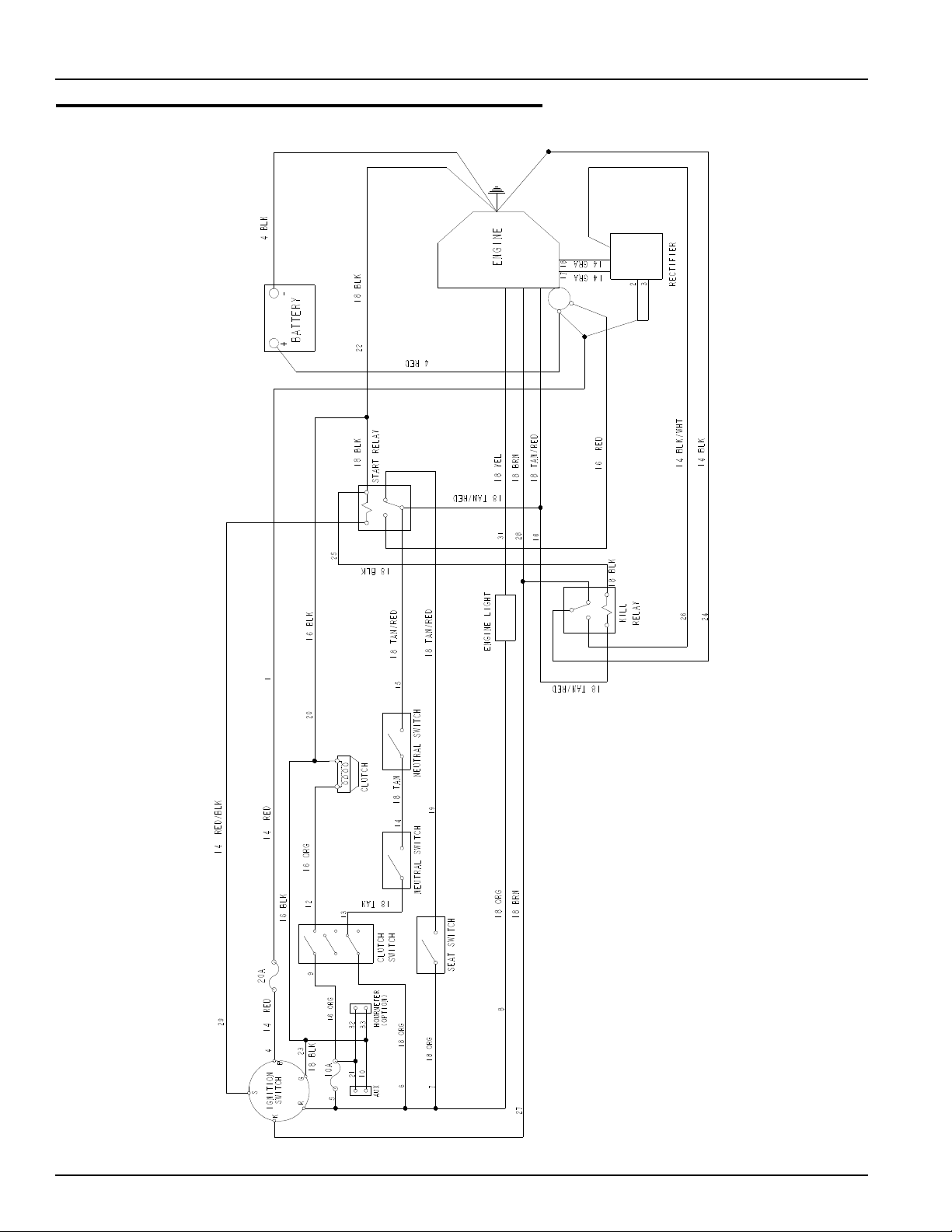
Honda Electrical Schematic (600998)
4-20 108277 10/08
Page 45

Chapter 5 Contents
Front Wheel Assembly. . . . . . . . . . . . . . . . . . . . . . . . . . . . . . . . . . . . 5-2
Front Wheel Breakdown . . . . . . . . . . . . . . . . . . . . . . . . . . . . . . . . . . 5-3
Drive Wheel Assembly. . . . . . . . . . . . . . . . . . . . . . . . . . . . . . . . . . . . 5-4
108277 10/08 5-1
Page 46

Front Wheel Assembly
1
2
3
4
4
5
6
7
8
8
9
8
1
2
3
4
4
5
6
7
8
11
11
10
1
2
3
3
3
3
INDEX NO.
1 705954 705954 2 CS .500-13 X 1.25 HX G5 ZNYC
2 344267 344267 2 FW .510 X 2.15 X .187 SPL ZNYC
3 712976 712976 2 FW .531 X 1.375 X .125 ZNYC
4 784223 784223 4 BEARING
5 784603 784603 2 FASTRAK SPACER
6 339689 339689 2 CASTER FORK
7 042630 042630 2 CS .500-13 X 6.50 HX G5 ZNYC
8 767962 767962 4 FW .531 X 1.063 X .090 SAE ZNYC
9 781567 781567 2 NT .500-13 HEX G8 ZNYC NL
10 768044 768044 2 TIRE/WHEEL ASSEMBLY 11 X 4-5 RIBBED
11 306969 306969 2 GAGE WHEEL SPACER
SERVICE
PART NO.
MFG. PART
NO.
QTY. DESCRIPTION
NOTES:
1. Apply grease to zerks, see owners manual.
2. Torque to 75 ft.-lbs.
3. Assemble with extended inner race down.
5-2 108277 10/08
Page 47

Front Wheel Breakdown
2
2
1
768044
INDEX NO.
1 772814 N/A 1 3/4" ROLLER BEARING
2 772806 N/A 2 BEARING CAP
SERVICE
PART NO.
1. Inflate to 8-12 psi.
MFG. PART
NO.
QTY. DESCRIPTION
NOTES:
108277 10/08 5-3
Page 48

Drive Wheel Assembly
1
1
2
3
4
5
2
INDEX
NO.
SERVICE
PART NO.
1 784264 784264 2 WHEEL/TIRE ASSY 18 X 9.50 (QTY PER 54" TRACTOR)
2 784272 N/A 1 TIRE 18 X 9.5
3 784280 N/A 1 WHEEL
4 019521 N/A 1 TIRE VALVE
5 061077 061077 4 WHEEL NUT (QTY PER WHEEL)
MFG. PART
NO.
QTY. DESCRIPTION
1 783134 783134 2 WHEEL/TIRE ASSY 18 X 8.50 (QTY PER 48" TRACTOR)
2 783142 N/A 1 TIRE 18 X 8.50
3 783159 N/A 1 WHEEL
4 019521 N/A 1 TIRE VALVE
5 061077 061077 4 WHEEL NUT (QTY PER WHEEL)
NOTES:
1. Inflate tire to 8-12 psi.
2. Torque to 65-75 ft-lbs.
5-4 108277 10/08
Page 49

Chapter 6 Contents
54" Deck Assembly . . . . . . . . . . . . . . . . . . . . . . . . . . . . . . . . . . . . . . 6-2
54" Deck Pulley Assembly. . . . . . . . . . . . . . . . . . . . . . . . . . . . . . . . . 6-4
48" Deck Assembly . . . . . . . . . . . . . . . . . . . . . . . . . . . . . . . . . . . . . . 6-6
48" Deck Pulley Assembly. . . . . . . . . . . . . . . . . . . . . . . . . . . . . . . . . 6-8
Blade Spindle Assembly Breakdown. . . . . . . . . . . . . . . . . . . . . . . . 6-10
108277 10/08 6-1
Page 50

54" Deck Assembly
2
9
14
8
10
6
12
6
5
7
4
4
11
5
5
5
5
17
17
12
12
12
13
13
13
14
14
13
15
15
16
16
16
15
15
11
17
11
6
5
14
1
3
6-2 108277 10/08
Page 51

54" Deck Assembly
1
INDEX NO.
1 548305 108100 1 DECK W/A 54" FASTRAK
2 601117 6 01117 1 DISCHARGE CHUTE ASSY
3 108537 108537 1 CHUTE MOUNTING PIN
4 034280 034280 3 CS .312-18X .750 HX G5
5 768523 768523 6 FW .343X.687X.051/.080H
6 034272 034272 3 NT .312-18 HX G5 ZNYC
7 767954 767954 2 FW .406X .812 X.060 SAE
8 086660 086660 2 NT .375-16 HXZY NL
9 025395 025395 2 CB .375-16X 1.00 STD CD
10 108049 108049 1 DISCHARGE CHUTE MOUNTING BRACKET
11 601069 601069 4 CN .312-18X.200 MAX THK
12 781708 N/A 4 CS .500-13X4.250 HX G5
13 767962 N/A 8 FW .531X 1.063X.090 SAE
14 031997 N/A 4 ANTI-SCALP WHEEL
15 053199 N/A 4 NT .500-13 HX JAM ZNYC
16 781567 781567 4 NT .500-13 H8ZY NL
17 787994 787994 2 DECK PIN & ROD ASSY
SERVICE
PART NO.
788166 788166 4 ANTI-SCALP WHEEL ASSY
MFG. PART
NO.
QTY. DESCRIPTION
NOTES:
1. Includes items 12 through 15.
2. Service part deck includes decals (see “54" Deck Decals” on page 8-4
for listing of decals).
108277 10/08 6-3
Page 52

54" Deck Pulley Assembly
2
1
2
3
5
7
10
14
13
15
16
8
11
12
17
4
4
5
19
20
20
20
19
20
19
19
21
22
20
22
23
24
26
14
13
25
27
54" Deck Assy
1
1
18
14
4
6
3
3
9
18
5
6-4 108277 10/08
Page 53

54" Deck Pulley Assembly
INDEX NO.
1 789388 789388 1 B-SECTION BELT
2 025007 025007 1 CS .625-11 X .75 HX G5
3 046821 046821 3 FW .656 X 2.00 X .078 ZNYC
4 797449 797449 3 FW .650X1.00X.180 ZNYC G5
5 784504 784504 3 5.00" OD, 5/8" IDLER PULLEY
6 028118 028118 1 FW .625 X 1.00 X .134 ZNYC
7 600296 600296 1 DECK IDLER SPACER
8 797910 797910 6 CS .312-18X1.50FLT SH ZY
9 601434 601434 2 IDLER SLIDE, UHMW
10 350884 350884 1 DECK IDLER
11 781302 781302 1 IDLER SPRING
12 259812 059931 1 SPRING CHAIN (13 LINKS)
13 781872 781872 6 CS .625-11X1.25 HX G5 Z
14 782474 782474 8 CW .631 2.250X .187 PNT
15 786889 786889 3 DECK DRIVE 5.0 PULLEY
16 108123 108123 1 PULLEY COVER LS
17 108124 108124 1 PULLEY COVER RH
18 016972 016972 2 NT .625-11 HX G5 ZNYC
19 064006 064006 4 CS .312-18X .625 HX G5
20 768523 768523 10 FW .343X.687X.051/.080H
21 054502 054502 12 NT .375-16 HX GRD 5 ZNYC
22 767954 767954 24 FW .406X .812 X.060 SAE
23 005116 005116 12 CS .375-16X1.375 HX G5
24 783506 783506 3 BLADE SPINDLE ASSEMBLY
25 058776 058776 6 NT .312-18 HXZY NL
26 601124 601124 3 18.50"-L-F-CW BLADE
27 783738 783738 2 CS .625-11X3.00 FULL HX
SERVICE
PART NO.
MFG. PART
NO.
QTY. DESCRIPTION
NOTES:
1. Torque to 118 ft.-lbs.
2. See “Deck Belt Routing and Tensioning” on page 7-5 for belt tensioning.
108277 10/08 6-5
Page 54

48" Deck Assembly
2
4
7
14
9
10
6
12
5
3
8
4
4
11
5
5
5
5
17
17
12
12
12
13
13
13
14
14
13
15
15
16
16
16
15
15
11
17
6
14
1
5
6-6 108277 10/08
Page 55

48" Deck Assembly
2
1
INDEX NO.
1 548313 108125 1 DECK W/A 48" FASTRAK
2 601117 6 01117 1 DISCHARGE CHUTE ASSY
3 108537 108537 1 CHUTE MOUNTING PIN
4 034280 034280 3 CS .312-18X .750 HX G5
5 768523 768523 6 FW .343X.687X.051/.080H
6 034272 034272 3 NT .312-18 HX G5 ZNYC
7 025395 025395 2 CB .375-16X 1.00 STD CD
8 767954 767954 2 FW .406X .812 X.060 SAE
9 086660 086660 2 NT .375-16 HXZY NL
10 108049 108049 1 DISCHARGE CHUTE MOUNTING BRACKET
11 601069 601069 4 CN .312-18X.200 MAX THK
12 781708 N/A 4 CS .500-13X4.250 HX G5
13 767962 N/A 8 FW .531X 1.063X.090 SAE
14 031997 N/A 4 ANTI-SCALP WHEEL
15 053199 N/A 4 NT .500-13 HX JAM ZNYC
16 781567 781567 4 NT .500-13 H8ZY NL
17 787994 787994 2 DECK PIN & ROD ASSY
SERVICE
PART NO.
N/A 788166 4 ANTI-SCALP WHEEL ASSY
MFG. PART
NO.
QTY. DESCRIPTION
NOTES:
1. Includes items 12 through 15.
2. Service part deck includes decals (see “48" Deck Decals” on page 8-5
for a listing of decals).
108277 10/08 6-7
Page 56

48" Deck Pulley Assembly
2
1
2
3
5
10
14
13
15
16
8
11
12
17
18
18
3
4
5
19
20
20
20
19
20
19
19
21
22
20
25
22
23
24
26
14
13
14
27
48" Deck Assy
1
1
4
6
7
4
3
9
14
5
6-8 108277 10/08
Page 57

48" Deck Pulley Assembly
INDEX NO.
1 791335 791335 1 B-SECTION BELT
2 025007 025007 1 CS .625-11 X .75 HX G5
3 046821 046821 3 FW .656 X 2.00 X .078 ZNYC
4 797449 797449 3 FW .650X1.00X.180 ZNYC G5
5 784504 784504 3 5.00" OD, 5/8" IDLER PULLEY
6 028118 028118 1 FW .625 X 1.00 X .134 ZNYC
7 600296 600296 1 DECK IDLER SPACER
8 797910 797910 6 CS .312-18X1.50FLT SH ZY
9 601434 601434 2 IDLER SLIDE, UHMW
10 350884 350884 1 DECK IDLER
11 781302 781302 1 IDLER SPRING
12 259812 059931 1 SPRING CHAIN (13 LINKS)
13 781872 781872 6 CS .625-11X1.25 HX G5 Z
14 782474 782474 8 CW .631 2.250X .187 PNT
15 792689 792689 3 DECK DRIVE 5.0 PULLEY
16 108148 108148 1 PULLEY COVER LS
17 108149 108149 1 PULLEY COVER RH
18 016972 016972 2 NT .625-11 HX G5 ZNYC
19 064006 064006 4 CS .312-18X .625 HX G5
20 768523 768523 10 FW .343X.687X.051/.080H
21 054502 054502 12 NT .375-16 HX GRD 5 ZNYC
22 767954 767954 24 FW .406X .812 X.060 SAE
23 005116 005116 12 CS .375-16X1.375 HX G5
24 783506 783506 3 BLADE SPINDLE ASSEMBLY
25 058776 058776 6 NT .312-18 HXZY NL
26 601123 601123 3 16.50"-L-F-CW BLADE
27 783738 783738 2 CS .625-11X3.00 FULL HX
SERVICE
PART NO.
MFG. PART
NO.
QTY. DESCRIPTION
NOTES:
1. Torque to 118 ft.-lbs.
2. See “Deck Belt Routing and Tensioning” on page 7-5 for belt tensioning.
108277 10/08 6-9
Page 58

Blade Spindle Assembly Breakdown
1
2
3
4
5
2
INDEX NO.
1 783548 N/A 1 BLADE SPINDLE RETAINING
2 783555 N/A 2 BEARING, BLADE SPINDLE
3 783530 N/A 1 SPACER, BLADE SPINDLE
4 783514 N/A 1 HOUSING, BLADE SPINDLE
5 783522 N/A 1 SHAFT, BLADE SPINDLE
SERVICE
PART NO.
MFG. PART
NO.
QTY. DESCRIPTION
NOTES:
6-10 108277 10/08
Page 59

Chapter 7 Contents
Seat Installation. . . . . . . . . . . . . . . . . . . . . . . . . . . . . . . . . . . . . . . . . 7-2
Deck Installation . . . . . . . . . . . . . . . . . . . . . . . . . . . . . . . . . . . . . . . . 7-4
Deck Belt Routing and Tensioning . . . . . . . . . . . . . . . . . . . . . . . . . . 7-5
108277 10/08 7-1
Page 60

Seat Installation
1
1
6
7
8
3
9
10
11
3
12
4
6
2
3
5
3
13
7-2 108277 10/08
Page 61

Seat Installation
INDEX NO.
1 793661 793661 1 MICHIGAN STANDARD SEAT
2 034280 034280 1 CS .312-18X .750 HX G5
3 768523 768523 9 FW .343 X .687 X .051/.080 HD
4 108321 108321 1 SEAT LATCH, 48/54 FST
5 808485 808485 1 5/16-18 RIVET NUT
6 000331 000331 2 SMALL/SHORT WIRE TIE
7 548776 107861 1 SEAT PAN
8 034272 034272 4 NT .312-18 HX G5 ZNYC
9 052860 052860 2 CS .375-16 X 1.25 HX G5
10 767954 767954 2 FW .406 X .812 X .060 SAE
11 601450 601450 2 SEAT SPRING 150 LB/IN
12 064014 064014 2 CS .312-18 X .875 HX G5
13 058776 058776 2 NT .312-18 HX ZNYC NL
SERVICE
PART NO.
MFG. PART
NO.
QTY. DESCRIPTION
NOTES:
1. Do not torque, Item 7 (107861 Seat Pan) must pivot.
2. Service parts, (Michigan seat):
793307 SLIDE KIT
793315 SWITCH-SNAP KIT
797464 LH ROUND ARMREST ASSEMBLY
797472 RH ROUND ARMREST ASSEMBLY
797480 MOLDED ROUND ARMREST (2)
793273 ARMREST STOP ASSEMBLY
108277 10/08 7-3
Page 62

Deck Installation
5
3
3
2
4
4
1
INDEX NO.
1 055749 055749 4 CS .437-14X1.750 HX G5
2 017616 017616 2 CS .500-13X1.750 HX G5
3 767962 767962 4 FW .531X 1.063X.090 SAE
4 704643 704643 8 NT .437-14 HX FLG ZN
5 008193 008193 2 NT .500-13 HX G5 ZNYC
SERVICE
PART NO.
MFG. PART
NO.
QTY. DESCRIPTION
NOTES:
7-4 108277 10/08
Page 63
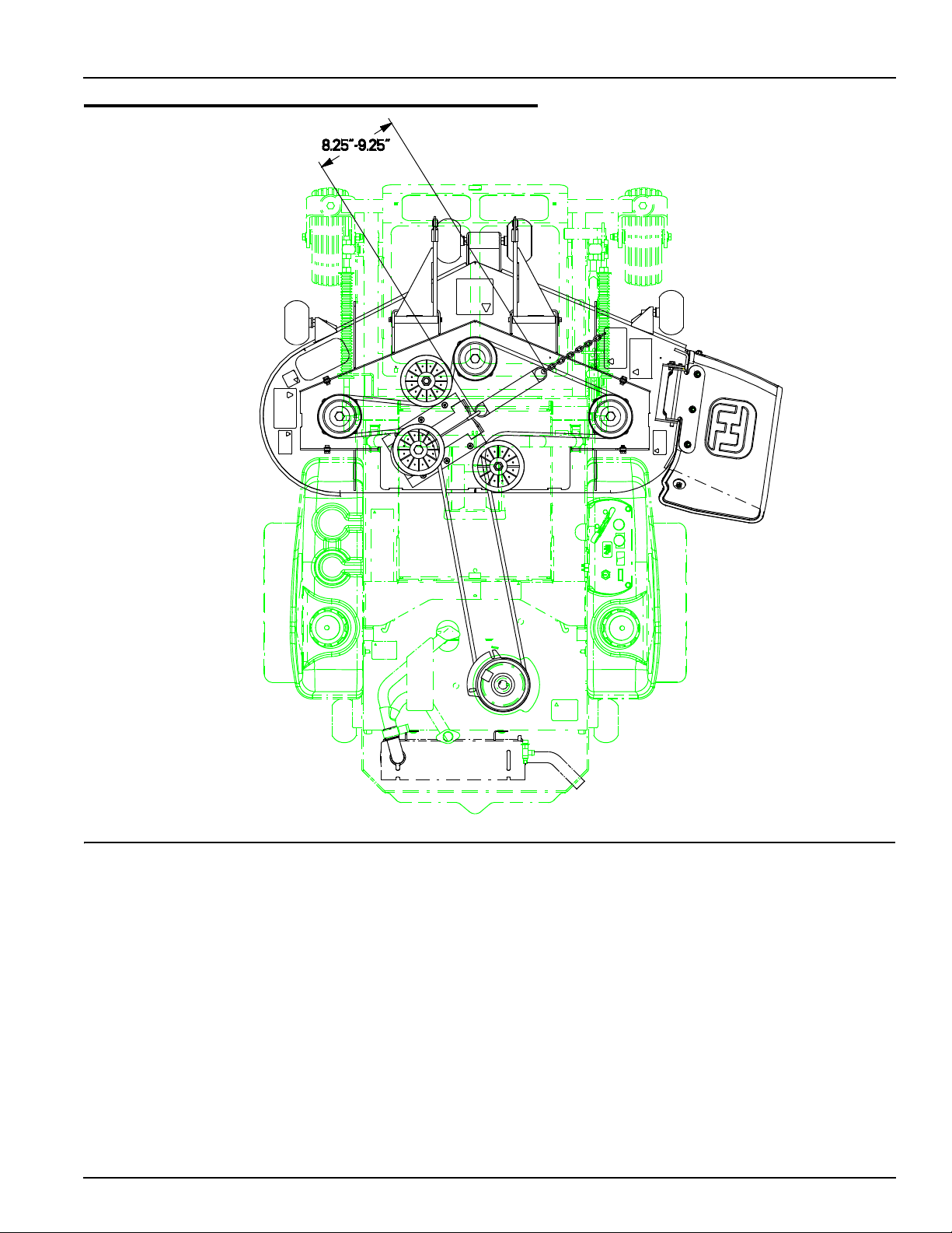
Deck Belt Routing and Tensioning
NOTES:
1. Spring length after tensioning new belt. Spring length measured from
outside of hook to outside of hook. Tension spring with deck in leveling
position.
2. Route belt as shown.
108277 10/08 7-5
Page 64

7-6 108277 10/08
Page 65

Chapter 8 Contents
Tractor Decals . . . . . . . . . . . . . . . . . . . . . . . . . . . . . . . . . . . . . . . . . . 8-2
54" Deck Decals . . . . . . . . . . . . . . . . . . . . . . . . . . . . . . . . . . . . . . . . 8-4
48" Deck Decals . . . . . . . . . . . . . . . . . . . . . . . . . . . . . . . . . . . . . . . . 8-5
108277 10/08 8-1
Page 66

Tractor Decals
16
15
7
4
2
1
3
8
9
10
11
12
13
14
17
18
5
6
8-2 108277 10/08
Page 67

Tractor Decals
INDEX NO.
1 785121 785121 1 OPERATION RIGHT DECAL
2 785139 785139 1 STEERING L.S. DECAL
3 N/A 083279 1 TURF PROD SERIAL NO PLATE
4 784710 784710 1 FASTRAK DECAL
5 727172 727172 1 'MADE IN U.S.A.' DECAL
6 782573 782573 1 FIRST ZERO TURN DECAL
7 793588 793588 1 HUSTLER NAME PLATE
8 785220 785220 1 STEERING R.S. DECAL
9 788968 788968 1 ENGINE COMPARTMENT DECAL
10 785154 785154 1 DECK HEIGHT DECAL
11 601100 601100 1 INSTRUMENT PANEL DECAL
12 791848 791848 1 FUEL INDICATOR DECAL
13 601099 601099 1 TOW VALVE DECAL
14 771436 771436 1 STABILIZER DECAL
15 600899 600899 1 PUMP BELT WARNING DECAL
16 727016 727016 1 BATTERY DECAL
17 785147 785147 1 SERVICE DECAL
18 600941 600941 1 PATENT DECAL
SERVICE
PART NO.
MFG. PART
NO.
QTY. DESCRIPTION
NOTES:
108277 10/08 8-3
Page 68

54" Deck Decals
1
2
3
4
6
3
2
5
7
INDEX NO.
1 799171 799171 1 54" DECK ID DECAL
2 727453 727453 2 BELT & PULLEY DECAL
3 727438 727438 2 WHIRLING BLADES DECAL
4 727172 727172 1 'MADE IN U.S.A.' DECAL
5 785055 785055 1 STEP TREAD 3.70 X 9.00
6 781419 781419 1 BELT ROUTING DECAL
7 727420 727420 1 DEFLECTOR SHIELD DECAL
SERVICE
PART NO.
MFG. PART
NO.
QTY. DESCRIPTION
NOTES:
8-4 108277 10/08
Page 69

48" Deck Decals
1
2
3
4
6
3
2
5
7
INDEX NO.
1 793976 793976 1 48" DECK ID DECAL
2 727453 727453 2 BELT & PULLEY DECAL
3 727438 727438 2 WHIRLING BLADES DECAL
4 727172 727172 1 'MADE IN U.S.A.' DECAL
5 794503 794503 1 STEP TREAD MINI FST DECAL
6 781419 781419 1 BELT ROUTING DECAL
7 727420 727420 1 DEFLECTOR SHIELD DECAL
SERVICE
PART NO.
MFG. PART
NO.
QTY. DESCRIPTION
NOTES:
108277 10/08 8-5
Page 70

8-6 108277 10/08
Page 71

Chapter 9 Contents
Assembly Pictures and Aids . . . . . . . . . . . . . . . . . . . . . . . . . . . . . . . 9-3
General Information for all models . . . . . . . . . . . . . . . . . . . . . 9-3
Wire harness routing (all models). . . . . . . . . . . . . . . . . . . . . . 9-3
FasTraks with Honda engines . . . . . . . . . . . . . . . . . . . . . . . . 9-4
FasTraks with Kawasaki engines . . . . . . . . . . . . . . . . . . . . . . 9-6
FasTraks with Kawasaki engines . . . . . . . . . . . . . . . . . . . . . . 9-9
FasTraks with Kohler Engines . . . . . . . . . . . . . . . . . . . . . . . 9-11
Maintenance & Adjustment Safety. . . . . . . . . . . . . . . . . . . . . . . . . . 9-14
Safe Maintenance & Adjustment Practices. . . . . . . . . . . . . . 9-14
Using a ramp. . . . . . . . . . . . . . . . . . . . . . . . . . . . . . . . . . . . . 9-15
Safety and Instruction Decals. . . . . . . . . . . . . . . . . . . . . . . . 9-15
Maintenance . . . . . . . . . . . . . . . . . . . . . . . . . . . . . . . . . . . . . . . . . . 9-18
Introduction. . . . . . . . . . . . . . . . . . . . . . . . . . . . . . . . . . . . . . 9-19
Torque values. . . . . . . . . . . . . . . . . . . . . . . . . . . . . . . . . . . . 9-20
Tires . . . . . . . . . . . . . . . . . . . . . . . . . . . . . . . . . . . . . . . . . . . 9-20
Lubrication . . . . . . . . . . . . . . . . . . . . . . . . . . . . . . . . . . . . . . 9-20
Electrical system. . . . . . . . . . . . . . . . . . . . . . . . . . . . . . . . . . 9-20
Access to ZT2800 transaxles . . . . . . . . . . . . . . . . . . . . . . . . 9-22
Hydraulic system. . . . . . . . . . . . . . . . . . . . . . . . . . . . . . . . . . 9-22
Fluid changing procedure . . . . . . . . . . . . . . . . . . . . . . . . . . . 9-23
Fuel system. . . . . . . . . . . . . . . . . . . . . . . . . . . . . . . . . . . . . . 9-24
Fuel Shut-off Valves . . . . . . . . . . . . . . . . . . . . . . . . . . . . . . . 9-25
Engine oil and filter . . . . . . . . . . . . . . . . . . . . . . . . . . . . . . . . 9-26
Belt replacement. . . . . . . . . . . . . . . . . . . . . . . . . . . . . . . . . . 9-27
Deck belt replacement . . . . . . . . . . . . . . . . . . . . . . . . . . . . . 9-28
108277 10/08 9-1
Page 72

Transaxle drive belt replacement. . . . . . . . . . . . . . . . . . . . . 9-29
Mower blade maintenance. . . . . . . . . . . . . . . . . . . . . . . . . . 9-29
Mower blade removal. . . . . . . . . . . . . . . . . . . . . . . . . . . . . . 9-31
Adjustment . . . . . . . . . . . . . . . . . . . . . . . . . . . . . . . . . . . . . . . . . . . 9-32
Introduction. . . . . . . . . . . . . . . . . . . . . . . . . . . . . . . . . . . . . . 9-32
Seat adjustment . . . . . . . . . . . . . . . . . . . . . . . . . . . . . . . . . . 9-32
Control lever adjustment . . . . . . . . . . . . . . . . . . . . . . . . . . . 9-32
Steering linkage . . . . . . . . . . . . . . . . . . . . . . . . . . . . . . . . . . 9-33
Control Lever Neutral Adjustment . . . . . . . . . . . . . . . . . . . . 9-33
Steering dampener. . . . . . . . . . . . . . . . . . . . . . . . . . . . . . . . 9-35
Drive straight adjustment:. . . . . . . . . . . . . . . . . . . . . . . . . . . 9-36
Park brake spring adjustment. . . . . . . . . . . . . . . . . . . . . . . . 9-36
Hydraulic pump belt adjustment. . . . . . . . . . . . . . . . . . . . . . 9-36
Deck drive belt adjustment. . . . . . . . . . . . . . . . . . . . . . . . . . 9-37
Engine RPM setting . . . . . . . . . . . . . . . . . . . . . . . . . . . . . . . 9-37
Deck leveling and height adjustment . . . . . . . . . . . . . . . . . . 9-37
9-2 108277 10/08
Page 73

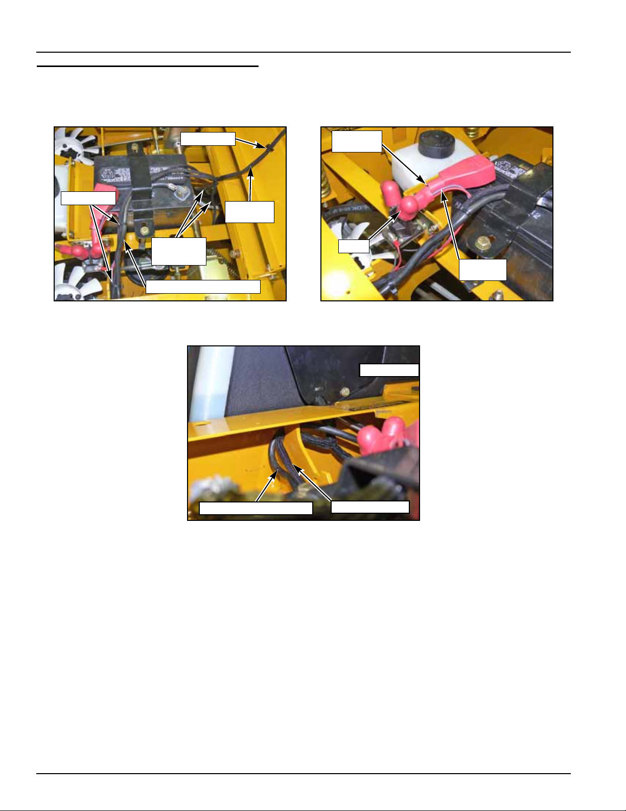
Assembly Pictures and Aids
PTO CLUTCH
SWITCH
TO SEAT
SWITCH
TIE STRAP
FROM SAFETY
SWITCHES
TIE STRAP
General Information for all models
Instrument panel layout (FIG. 1).
Wire harness routing (all models).
Front of wire harness (FIG. 2 & FIG. 3).
FIG. 1
FIG. 2 FIG. 3
9-3 108277 10/08
Page 74

FasTraks with Honda engines
CHOKE &
THROTTLE
CABLES
TIE STRAPS
SEAT
SWITCH
WIRE
SAFETY
SWITCH
WIRES
TIE STRAP
TIE STRAPS
NEGATIVE
BATTERY
CABLE
POSITIVE
BATTERY
CABLE
FUEL LINE
OIL SENSOR
WIRE
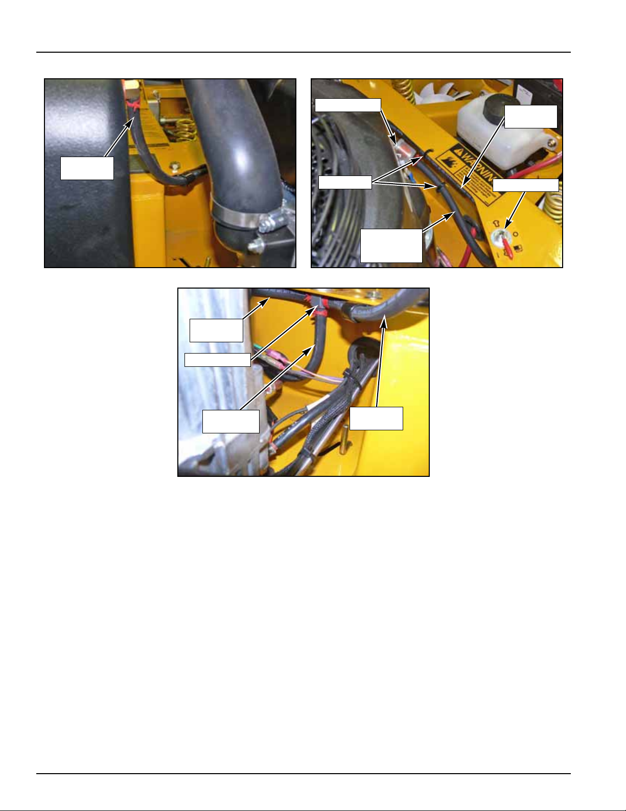
Wire harness, battery cable, throttle cable, and choke cable routing and tie straps (FIG. 4 & FIG. 5).
FIG. 4
NOTE: Tie straps on rear seat support tie fuel line from L.S. fuel tank.
FIG. 5
9-4 108277 10/08
Page 75

Engine connections )FIG.6, FIG. 7, F IG. 8, and FIG. 9).
OIL
SENSOR
WIRE
FUEL
LINE
TIE STRAP
CARBURETOR
DRAIN
TUBES
TIE STRAP
CLUTCH
ANCHOR
OIL
SENSOR
WIRE
FUEL
LINE
OIL
FILL
TUBE
THROTTLE
CABLE
CHOKE
CABLE
FIG. 6 FIG. 7
FIG. 8 FIG. 9
NOTE: Route oil sensor wire between oil file tube and engine block. Index terNOTE: Tie carburetor drain tubes and clutch pigtail to gether to clutch anchor .
minal on wire in horizontal direction to hold wire off oil filter.
Do not tighten tie strap enough to pinch drain hoses closed.
9-5 108277 10/08
Page 76
FasTraks with Kawasaki engines
TO SEAT
SWITCH
TIE STRAP
TIE STRAP
FROM
SAFETY
SWITCHES
NEG. BATTERY CABLE
POS. BAT.
CABLE
PUR/RED
WIRES
BOOT
WIREHARNESS
NEG. BATTERY CABLE
RIGHT SIDE
FOR MOWERS WITH SERIAL NUMBER 07102604 AND HIGHER.
Front of wire harness (FIG. 10). Route the 4" positive battery cable and the purple and red wires through the cable
boot prior to fastening hardware to solenoid (FIG. 11).
FIG. 10 FIG. 11
Route negative battery cable and wireharness (from seat a nd safety switches) through hole in the right side of frame
(FIG. 12).
FIG. 12
9-6 108277 10/08
Page 77

Wire harness, battery cable, and throttle and choke cable, routing and tie straps (FIG. 13 & FIG. 14) .
FUEL LINE
GROUND
WIRE
CHOKE AND
THROTTLE
CABLES
TIE STRAP
NEGATIVE
BATTERY
CABLE
CLUTCH
PIGTAIL
CLUTCH
WIRE
TIE STRAP
POSITIVE
BATTERY
CABLE
FUEL LINE
TIE
STRAP
CLUTCH
PIGTAIL
TIE STRAP
SAFETY SWITCH
TIE STRAPS
OIL SENSOR
WIRE
OIL FILL
TUBE
CHOKE CABLE
THROTTLE CABLE
THROTTLE
CABLE
CHOKE
CABLE
FIG. 13 FIG. 14
Clutch pigtail to clutch anchor tie strap (FIG. 15).
Safety switches and tie straps (FIG. 16)
Engine connections (FIG. 17 & FIG. 18).
FIG. 15 FIG. 16
FIG. 17 FIG. 18
9-7 108277 10/08
Page 78
Fuel line routing (FIG. 19, FIG. 20 & FIG. 21).
LEFT
FUEL LINE
LEFT
FUEL LINE
TIESTRAP
FUEL FILTER
FUEL LINE
FROM FUEL
VALVE
FUEL VALVE
FUEL VALVE
LEFT
FUEL LINE
RIGHT
FUEL LINE
FUEL LINE
TO FILTER
Be sure fuel filter does not come in contact with engine.
FIG. 19 FIG. 20
FIG. 21
9-8 108277 10/08
Page 79
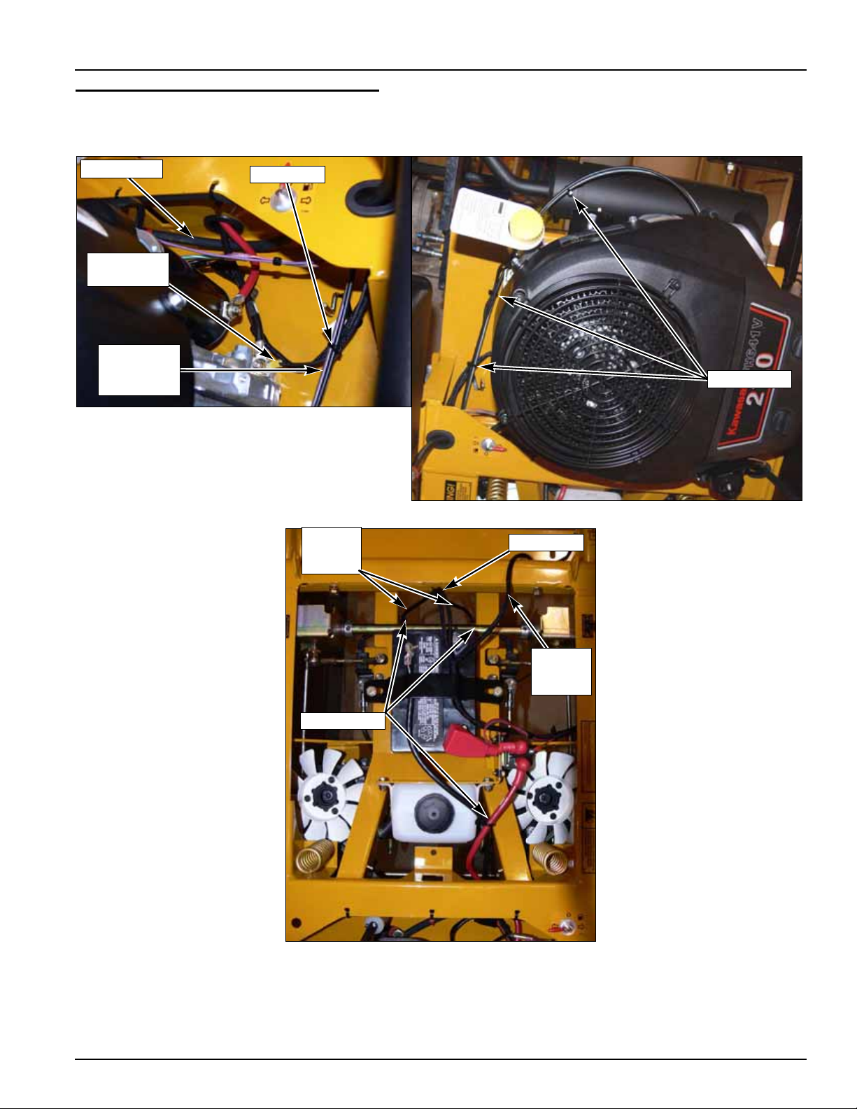
FasTraks with Kawasaki engines
FUEL LINE
TIE STRAP
GROUND
WIRE
CHOKE AND
THROTTLE
CABLES
TIE STRAPS
TIE STRAPS
TIE STRAP
SEAT
SWITCH
WIRE
SAFETY
SWITCH
WIRES
FOR MOWERS WITH SERIAL NUMBERS PRIOR TO 07102604:
Wire harness, battery cable, and throttle and choke cable, routing and tie straps (FIG. 22, FIG. 23, & FIG. 24) .
FIG. 22 FIG. 23
FIG. 24
NOTE: Route fuel line beneath both battery cables. Tie straps on rear seat
support tie fuel line from L.S. fuel tank.
9-9 108277 10/08
Page 80

Engine connections for 19 HP (FIG. 25 & FIG. 26).
THROTTLE
CABLE
CHOKE
CABLE
OIL
SENSOR
WIRE
TIE
STRAP
CHOKE
CABLE
THROTTLE
CABLE
OIL
SENSOR
WIRE
FIG. 25 FIG. 26
Engine connections for 21 HP (FIG. 27 & FIG. 28).
FIG. 27 FIG. 28
9-10 108277 10/08
Page 81

FasTraks with Kohler Engines
TIE STRAPS
TO SEAT
SWITCH
TIE STRAP
TIE STRAP
FROM
SAFETY
SWITCHES
NEG. BATTERY CABLE
POS. BAT.
CABLE
PUR/RED
WIRES
BOOT
WIREHARNESS
NEG. BATTERY CABLE
RIGHT SIDE
FOR ENGINES WITH SERIAL NUMBERS PRIOR TO 07102604 (FIG. 29):
FIG. 29
FOR ENGINES WITH SERIAL NUMBERS 07102604 AND HIGHER:
Front of wire harness (FIG. 30). Route the 4" positive battery cable and the purple and red wires through the cable
boot prior to fastening hardware to solenoid (FIG. 31).
Route negative battery cable and wireharness (from seat a nd safety switches) through hole in the right side of frame
(FIG. 32).
FIG. 30 FIG. 31
FIG. 32
9-11 108277 10/08
Page 82

Wire harness and battery cable, and throttle and choke cable, routing and tie straps (FIG. 33, & FIG. 34) .
TIE
STRAP
FROM
BATTERY
TIE
STRAP
TIE
STRAP
CHOKE
CABLE
THROTTLE
CABLE
FIG. 33 FIG. 34
NOTE: Tie strap on rear seat support (FIG. 33) ties fuel line from L.S. fuel t ank
similar to Kawasaki engines. See Fuel line routing (FIG. 19, FIG. 20 &
FIG. 21). on page 9-8.
Engine connection
(FIG. 35).
FIG. 35
9-12 108277 10/08
Page 83

Clutch pigtail to clutch anchor tie strap (FIG. 36).
TIE
STRAP
CLUTCH
PIGTAIL
FIG. 36
9-13 108277 10/08
Page 84

Maintenance & Adjustment Safety
This safety alert symbol is used to call attention to a message intended to provide a reasonable degree of PER-
SONAL SAFETY for operators and other persons during the normal operation and servicing of this equipment.
DANGER
WARNING
This manual uses two other words to highlight information. IMPORTANT calls attention to special mechanical infor-
mation and NOTE: emphasizes general information worthy of special attention.
All operators should read this manual, or be instructed about safe operating and maintenance procedure s. Th is is
the owner’s responsibility.
Improper use or maintenance by the operator, mechanic, or owner can result in injury. To reduce the potential for injury, comply with these safety instructions and always pay attention to the safety alert
which means DANGER or WARNING—“personal safety instructions.” Failure to comply with the instructions
may result in personal injury or death.
Incorrect usage of this machine may result in severe injury. Personnel operating and maintaining it should
be trained in the proper use and should read the manuals completely and thor oughly befo re att empt ing to se tup, operate, adjust, or service this machine.
The Quick Reference Decals, located in front of and to the right of the seat, are designed to give the operator/
mechanic brief information needed in the daily operation and service of the machine. These decals are no t inte nded to
be used in place of this manual but instead is to be used as an extension of this manual. These decals should not be
removed or obliterated. Replace these decals if they become unreadable.
It is the owner’s responsibility to make certain th at the operator/mech anic reads and un derstands this man ual and
all decals before operating this machine. It is also the owner’s responsibility to make certain that the operator/
mechanic is a qualified and physically able individual, properly trained in the operation of this equipment. Local regulations may restrict the age of the operator/mechanic.
The owner should also ensure that the operator/mechanic knows that they are responsible for their own safety as
well as the safety of other persons within the vicinity. Remember, the operator/mechanic is responsible for accident s or
hazards occurring to other people or their property.
—denotes immediate hazards which WILL result in severe personal injury or death.
—denotes a hazard or unsafe practice which COULD result in severe personal injury or death.
symbol,
?
Safe Maintenance & Adjustment Practices
This product is capable of amputating hands and feet and throwing objects. Always follow all safety instructions to
avoid serious injury or death.
?
Unless specifically required, DO NOT have engine running when servicing or making ad justments to tra ctor . Place
control levers in the park brake position, disengage deck clutch, remove ignition switch key and disconnect the
negative battery cable. Repairs or maintenance requ iring engine power sh ould be performed b y trained perso nnel
only. To prevent carbon monoxide poisoning, be sure proper ventilation is available when engine must be operated in an enclosed area.
?
Follow daily and weekly checklists, making sure hoses are tightly secured and bolts are tightened.
?
Keep your machine clean and remove any deposits of trash and clippings, which can cause engine fires and
hydraulic overheating as well as excessive belt wear. Clean up oil or fuel spillage. Allow machine to cool before
storing.
?
Clean flammable material from machine. Prevent fires by keeping engine compartment, batt ery, hydraulic
lines, fuel line, fuel tank and operator’s station clean of accumulated trash, grass clippings, and other
debris. Always clean up spilled fuel and oil.
?
Always wear adequate ear protection, such as earplugs, when operating this e quipment as prolonged exposu re to
uncomfortable or loud noises can cause impairment or loss of hearing. Do not wear radios or music headphones
while operating the machinery. Safe operation requires your full attention.
?
Never put hands or feet under any part of the machine while it is running.
9-14 108277 10/08
Page 85

?
Except when changing or checking belt, always keep belt covers on mower for safety as well as cleanliness.
?
Stop the engine before removing the grass catcher or unclogging the discharge chu te . Never clear the discharge
chute with the engine running. Turn off the engine and be sure the blades have stopped before cleaning. Use a
stick to clear a plugged discharge area. Never use your hand!
?
Exercise caution when loading or unloading the machine onto a trailer or truck.
?
Always wear safety goggles or safety glasses with side shields when operating the mower.
?
Never leave machine unattended with ignition key in switch, especially with children present.
?
Be alert and turn the machine off if children enter the area.
?
Always wear adequate eye protection when servicing the battery, hydraulic system, cooling system or when grinding mower blades and removing accumulated debris.
?
Use extra caution when handling gasoline and other fuels. They are flammable and vapors are explosive.
?
Never refuel tractor while engine is running; never refu el near an open flame or near devices which can create a
spark. Refuel outdoors preferably, or in well ventilated areas.
?
Never attempt to start engine when there is a strong odor of gasoline fumes present. Locate and correct cause.
?
Never run the engine in an enclosed area unless exhaust is vented to the outside. Exhaust gases contain carbon
monoxide which is odorless and deadly poison.
?
Never attempt to make any adjustments or repairs to the tractor drive system, mower deck or any attachment
while the tractor engine is running or deck clutch is engaged. Repairs or maintenance requiring engine power
should be performed by trained personnel only.
?
Never work under the machine or att achment unless it is safely supported with jack st ands. Make cert ain machine
is secure when it is raised and placed on the jack stands. The jack stands should not allow the machine to move
when the engine is running and the drive wheels are rotatin g. Use only certified jack stands. Use only appropri-
ate jack stands, with a minimum weight rating of 2000 pounds to block the unit up. Use in pairs only. Follow the
instructions supplied with the vehicle stands.
?
Before working on or under the deck, ma ke ce rtain eng ine cannot be accidentally started. Shut engine off and
remove ignition switch key for maximum safety. Repairs or maintenance requiring engine power should be performed by trained personnel only.
?
Use a stick or similar instrument to clean under the mower making sure that no part of the body, especially arms
and hands are under mower.
?
Exercise caution when working under the deck as the mower blades are extremely sharp. Wearing gloves or
wrapping the blade(s) is advisable when working around or with the blades.
?
Do not touch hot parts of machine.
?
Keep nuts and bolts tight, especially the blade attachment bolts. Keep equipment in good condition.
?
Never tamper with safety devices. Check their proper operation regularly.
?
Grass collection system components are subject to wear, damage and deterioration, which could expose moving
parts or allow objects to be thrown. Frequently chec k components an d replace with manufacturer’s recommended
parts, when necessary.
?
Use only genuine Hustler replacement parts to ensure that original standards are maintained
Using a ramp
?
Use extreme caution when loading and unloading a unit with a ramp.
?
Use only a single, full width ramp; do not use individual ramps for each side of the unit. Having a full width ramp
provides a surface for the tractor frame to contact if the unit starts to tip backwards. It also reduces the risk of a
wheel going off and the machine tipping over.
?
Do not exceed a 15 degree angle between the ramp and the ground or between the ramp and the trailer or truck.
?
When on a ramp avoid sudden acceleration
Safety and Instruction Decals
?
Specific safety warning decals are located on the equipment near the immediate areas of potential hazards.
These decals should not be removed or obliterated. Replace them if they become non-readable.
9-15 108277 10/08
Page 86

The following illustrations show the various decals that are located on the machine. A brief explanation, for those
Part Number
727016
Part Number
771436
Part Number
788968
Part Number
727420
Part Number
727438
requiring one, is shown to help the operator understand the meanings of these decals.
Read Owner’s Manual and Quick Reference Decal before attempting to operate this machine.
Avoid skin contact with battery acid.
Always wear eye protection when checking the battery, acid can cause serious injury to skin and
eyes. If contact occurs, flush area with clean water and call physician immediately. Acid will also
damage clothing.
Do not allow open flame near the battery when charging.
Hydrogen gas forms inside the battery. This gas is both toxic and flammable and may cause an
explosion if exposed to flame. Always remove the negative ground first and replace it last.
Do not overfill battery.
Electrolyte may overflow and damage paint, wiring or structure. When cleaning the battery, use
soap and water. Be careful no t to get soap and wa ter into the battery. Use soda mixed in water to
clean corrosion off the terminals.
Do not remove or modify stabilizer wheels or rear engine guard or injury can result.
Keep engine and pump compartment(s) clean (especially in exhaust area) to prevent fire
and provide maximum engine and hydraulic cooling.
Do not smoke while refueling.
Do not fill tank with engine running, or while the engine is hot.
Allow engine to cool before storing machine inside a building.
Store away from open flame or spark if there is fuel in tank.
Clean up any gasoline spills.
Do not refuel while in enclosed trailer or other enclosed areas.
Never operate the mower deck with side deflector remove d or in raised positio n, except when the
grass catcher attachment is being used.
Whirling blades! Keep hands and feet away.
Beware of thrown objects.
9-16 108277 10/08
Page 87

Keep shields or covers in place while machine is in operation.
Part Number
727453
Part Number
600899
Keep hands away from rotating pulleys and belts.
If you lose steering control while operating the machine, place the steering control levers in
the park brake position immediately. Inspect the machine and involve your Hustler dealer to
resolve the problem before continuing to operate.
If pump belt fails, steering control will be lost. Refer to owner’s manual for inspection and
replacement intervals and refer to above paragraph for emergency procedures.
9-17 108277 10/08
Page 88

Maintenance
13
Viewed from top of unit
12
14
14
1
3
2c
3b
8
15
11
11
10
10
6
6
5
7
7
16
2a
2b
9
4
Viewed from top of unit
1 Engine Oil Fill & Dipstick
2a. Fuel Filter (Honda)
2b. Fuel Filter (Kawasaki)
2c. Fuel Filter (Kohler)
3. Engine Air Cleaner
4. Engine Oil Drain Plug
5. Battery
6. Fuel Tanks
7. Gauge Wheel Bearing Zerks (2)
8. Engine Oil Filter
9. Deck Lift Pivot Zerks (4)
10. Park Brake Switch (2)
11. Drive Tire
12. Deck Belt
13. Pump Belt
14. Blades
15. Engine Air Intake Screen
16. Front Gauge Wheel Tires
9
Maintenance Locator Chart
FIG. 37
9-18 108277 10/08
Page 89

WEEKLY
SERVICE AT INTERVALS INDICATED
Verify safety start interlock system Prior to each use
Visually inspect unit for loose
hardware and/or damaged parts Prior to each use
Visually inspect tires Prior to each use
Check oil level, engine (1) Prior to each use or every 4 hours
Clean air intake screen (4) Prior to each use or every 4 hours
Clean foam element (4) Prior to each use or every 4 hours
Check fuel level Prior to each use
Blades - sharpen & securely fastened Prior to each use
Discharge chute - securely in place &
in lowest position Prior to each use
Check hydraulic oil level Daily
Clean engine and transaxle
compartment Daily
Change transaxle oil and filter (7) Every 200 hours or 2 years
Grease deck height pivots X
Grease gauge wheel bearings X
Change engine oil and filter (1) (3) X
Clean cylinder and head fins(a) X
Check battery connections X
Check tire pressure with a gauge X
Check hydraulic oil level X
Clean engine exterior (a) X
Clean & re gap spark plugs (a) X
Check pump and deck belt tension
and condition (5) X
Check fuel and hydraulic lines (6) X
Check fuel valve and grommet (6) X
Tighten lug nuts on wheels (2) X
Change fuel filter X
Replace spark plugs X
NOTES:
1. Initial oil change is after 5 hours of operation. Thereafter, change oil after every 40 hours operation. Change more
often under dusty or dirty conditions and dur ing hot weather periods.
2. Torque initially and after first 2 hours of operation.
3. Cha nge engi ne oil filter per the engi ne manufactur er’s recommenda tions. Refer to Engine Owner’s Manual for recommendations and other mainte na nce items.
4. Service more often under dusty or dirty conditions.
5. Pump driv e belt only - Inspect every 6 months or 100 hours and replace if worn or cracking is noticed. Other-
wise, replace every 200 hours or 2 years whichever comes first.
6. Check fuel line hoses, fuel valve and grommets for any cracks or leaks
7. Initial system oil and filter change mus
ter, replace filter and oil in each transaxle every 2 years or 200 hours, whichever comes first.
REFERENCES:
t be after the first 75 hours of use or 1 year whichever comes first. Thereaf-
OR 50
HOURS
MONTHLY
OR 100
HOURS
ANNUALLY
OR 300
HOURS
a --Refer to Engine Owner’s Manual
NOTE: After completing maintenance cycle (300 hours), repeat cycle.
Introduction
Regular maintenance is the best prevention for costly downtime or expensive, premature repair. The following
pages contain suggested main tena nce infor mation and sche du les which the opera to r should follo w on a ro utine basis.
Remain alert for unusual noises, they could be signaling a problem. Visually inspect the machine for any abnormal
9-19 108277 10/08
Page 90

wear or damage. A good time to detect potential problems is while performing scheduled maintenance service. Correcting the problem as quickly as possible is the best insurance.
Clear away heavy build-up of grease, oil and dirt, especially in the engine and under the seat platform areas; minute
dust particle are abrasive to close-tolerance engine and hydraulic assemblies.
Daily inspect mower for grass clippings and wire and string tangles. The underside of the mower deck will collect a
build-up of grass clippings and dirt, especially when grass is wet or has high moisture content. This build-up will
harden, restricting blade and air movement and will probably show a poorer quality of cutting. Therefore it should be
removed routinely.
To do this it will be necessary to raise and block the deck, using jack stands or blocks, in the full up position and
scrape the build-up from underneath.
Some repairs require the assistance o f a trained service mecha nic and should not be attempte d by unskilled personnel. Consult your Hustler service center when assistance is needed.
Torque values
Torque values are given below:
Wheel (lug) nuts 65-75 FT.-LBS.
Blade spindle bolt top 118 FT.-LBS.
Blade spindle bolt bottom 118FT.-LBS.
Lug nuts only - It is recommende d that these be checked af ter the first 2 hours of opera tion, initially, every 50 hours
and following removal for repair or replacement.
For all other torques refer to the various tractor parts manuals for standard torque chart. See page 21 for ordering
information.
For engine torque values, see engine owner’s manual.
Tires
It is important for level mowing that the tires have the same amount of air pressure. The recommended pressure
are:
Drive Wheels 8-12 PSI
Front Wheels 8-12 PSI
Solid fill tires are not recommended
ranty claim will be denied.
WARNING: Explosive separation of a tire and rim can cause serious injury or death. Do no t attempt
to mount a tire without the proper equipment and experience to perform the task. Alwa ys maint ain the
correct tire pressure and neve r over inflate. Never weld or heat a wheel and tire asse mbly as an
explosion may occur. Welding can weaken or deform a wheel. When inflating tires stand to one side
and not in front of or over the tire assembly. Check tires for low pressure, blemishes, damaged rims
or missing lug bolts and nuts.
for Hustler turf equipment. On any machine, with solid filled tires, the war-
Lubrication
1. Grease the front gauge wheel bearings per the Maintenance Schedule. Use SAE multi-purpose grease.
2. Grease the four deck lift pivots, located to the side of the operator’s footrest per the Maintenance Schedule. Use
SAE multi-purpose grease.
Electrical system
The electrical system is a 12-volt, negative ground. Recommended battery size is a garden tractor BCI group U1R
with 225 or better cranking AMP rating. A maintenance-free battery is recommended. Otherwise, follow battery manufacturer’s maintenance, safety, storing and charging specificatio ns .
9-20 108277 10/08
Page 91

The battery is located under the seat platform. FIG. 38
ZT2800
BATTERY
EXPANSION TANK
WARNING: Battery posts, terminals, and related accessories contain lead and lead compounds,
chemicals known to the State of California to cause cancer and reproductive harm. Wash hands after
handling.
FIG. 38
WARNING: Avoid skin and clothing contact with battery acid. Always wear eye protection when
checking the battery, acid can cause serious injury to skin and eyes. If contact occurs, flush area with
clean water and call physician immediately. Acid will also damage clothing. Do not drink the battery
electrolyte. Do not allow open flame near the battery when charging. Hydrogen gas forms inside the
battery. This gas is both toxic and flammable and may cause an explosion if exposed to flame.
Always remove the negative ground first and replace it last. Do not overfill battery. Electrolyte may
overflow and damage paint, wiring or structure. When cleaning the battery, use soap and water. Be
careful not to get soap and water into the battery. Clean the battery terminals with a solution of four
parts water and one part baking soda when they become corroded.
WARNING: Short s ca used by battery termina ls or met a l tools touching met a l tractor compone nt s can
cause sparks. Sparks can cause a battery gas explosion which will result in personal injury. Prevent
the battery terminals from touching any metal tractor parts when removing or installing the battery. Do
not allow metal tools to short between the battery terminals and metal tractor parts.
WARNING: Incorrect battery cable routing could cause damage to the tractor and battery cables.
This can cause sparks which can cause a battery gas explosion which will result in personal injury.
Always disconnect the negative (black) battery cable before disconnecting the positive (red) cable.
Always connect the positive (red) battery cable before connecting the negative (black) cable.
Common circuit failures are usually caused by shorting, corroded or dirty terminals; loose connections, defective
wire insulation or broken wires. Switches, solenoids and ignition components may also fail, causing a shorted or open
circuit.
The electrical system is protected by fuses located on the right fu el tank instrument panel. FIG. 39 The fuses are as
follows:
Function Size Type
Main 20 amp, blade-type
Before attempting any failure diagnosis of the electrical system, use a test light or voltmeter to check the battery
Clutch/Aux 10 amp , blade-type
9-21 108277 10/08
Page 92

FIG. 39
FUSES
voltage. If the battery voltage is satisfactory, check the cleanliness and tightness of the terminals and ground connections. A general understanding of electrical servicing and use of basic test equipment is necessary for troubleshooting
and repair.
Major overhaul or repair of the startin g motor or charging system should be performed by trained technicians only.
Access to ZT2800 transaxles
The integrated pump/motor units are accessed by lifting the seat platform. The seat platform is hinged at the front.
To raise it, remove the lock nut and tilt seat platform up and forward.
If the seat is equipped with the optional arm rest kit, make cert ain to place the control arms in the p ark brake
position and pivot the arm rest s upwar d before placin g the s eat plat f orm in the full forwa rd position to prev ent
damage to the arm rests.
Hydraulic system
The FasTrak 48/54 is equipped with two Hydro-Gear ZT 2800 transaxles (FIG. 38).
IMPORTANT: Never use hydraulic or automatic transmission fluid in this system; use only motor oil as specified.
Remember, dirt is the primary enemy of any hydraulic system.
The hydraulic expansion tank is located in front of the engine and under the operator’s platform (FIG. 40).
Check oil level in hydraulic system prior to each use. Check more often if system appears to be leaking or otherwise
malfunctioning.
Fluid level should be at the “Full Cold” line on the expansion tank. Use only SAE 20W50 SL service motor oil.
Change the system oil and filters after the first 75 hours of use or 1 year whichever comes first. Thereafter, replace
filter and oil in each transaxle every 2 years or 200 hours, whichever comes first. NOTE: The filter guard must be
removed to access filter.
Each transaxle’s filter is located per FIG. 41. A standard oil filter wrench is used to change filter, threads are right
handed. Use a Hustler approved filter element only.
9-22 108277 10/08
Page 93

FIG. 40 FIG. 41
ZT2800
FILTER GUARD
ZT2800 FILTER
FILTER GUARD
SCREW
SCREW
FIG. 42
WARNING: When washing the mower, direct the spray away (especially if using a power washer)
from the Hydro-Gear ZT 2800 transaxle’s seals to prevent water intrusion and to ensure component
performance.
WARNING: Make sure the transaxles are cool before performing service procedures.
Fluid changing procedure
1. Par k the unit on a level surface. Place co ntrol levers in the p ark br ake position, diseng age deck clutch, re move ignition switch key and disconnect negative battery cable.
2. Remove the three 1/4” filter guard screws and filter guard. Clean any loose debris from around the filter (FIG. 42).
3. Place an oil drain pan beneath the oil filter and remove the oil filter from the transaxle. By removing the filter, this
also drains the system oil.
4. After the oil has been drained, wipe the filter base surface off and apply a film of new oil to the gasket of the new
replacement filter.
5. Install the new filter by hand, turn 3/4 to one full turn after the filter gasket contacts the filter base surface.
6. Re-install the filter guard with three 1/4” screws. Torque the screws to 65 in.-lbs. each.
7. Repeat steps 2 - 6 for the opposite side transaxle.
8. Drain oil filters of all free flowing oil prior to disposal. Place used oil in appr opriate containers.
9. Remove the top port plug from the left side and right side transaxles prior to filling with oil. This will allow the
transaxles to vent during oil fill.
10.Remove the cap from the transaxle's expansion tank.
11. Fill oil reservoir with 20W-50 motor oil until oil just appears at the bottom of each transaxle’s top port (approximately 2 qts. per transaxle, 4 qts. total). Install the top port plug into each transaxle as the oil level reaches this
port.
12.nstall and torque the top port plugs to 180 in. lbs.
9-23 108277 10/08
Page 94

13.Continue to fill the transaxles through the expansion tank until the “Full Cold” line is reached on the expansion tank.
FUEL TANK
14.Re-install the expansion tank cap by hand. Be careful not to overtighten.
Fuel system
DANGER: Observe usual fuel handling precautions:
Do not smoke while refueling.
Do not fill tank with engine running or while engine is hot. Clean up any gasoline spills.
Allow engine to cool before storing machine inside a building.
Keep fuel away from open flame or spark and store machine away from open flame or spark if there is
fuel in the tank.
Use extra caution when handling gasoline and other fuels. They are flammable and vapors are explosive. A fire or explosion from gasoline can burn you and others and can damage property.
Refuel outdoors preferably, or in well ventilated areas.
Never attempt to start engine when there is a strong odor of gasoline fumes present. Locate and correct cause.
Store gasoline in an approve d container and keep it out of the reach of children. Never buy more than
a 30 day supply of gasoline.
Always place gasoline containers on the ground away from your vehicle before filling.
Do not fill gasoline containers inside a vehicle or on a truck or trailer as interior carpets or plastic truck
bed liners may insulate the container and slow the loss of any static charge.
When practical, remove equipment from the truck or trailer and refuel the eq uipment with its wheels o n
the ground. If this is not possible, then refuel the equipment on the truck or trailer using a portable container and not a gasoline dispen ser nozzle. If a gasoline dispenser n ozzle must be used, keep the nozzle in contact with the rim of the fuel tank or container opening at all times until fueling is complete.
WARNING: Gasoline is harmful or fatal if swallowed.
Long-term exposure to vapors can cause serious injury and illness.
Avoid prolonged breathing of vapors.
Keep face away from nozzle and gas tank or conditioner opening.
Keep gas away from eyes and skin.
The fuel tanks are located in the tractor’s fenders (FIG. 43). Total capacity for the fuel tanks is 10 U.S. gallons (38
liter).
FIG. 43
When filling the fuel tanks disengage deck clutch, place control levers in park brake position, and stop tractor
engine. Clean around the fuel tank cap and remove the cap and begin filling. When finished, screw the cap on securely
and wipe up any spilled gasoline.
Use regular unleaded gasoline with an octane rating of 87 or higher.
taining methanol, or gasohol containing more than 10% ethanol because the fuel system could be damaged. Do not
mix oil with gasoline.
9-24 108277 10/08
IMPORTANT: Never use methanol, gasoline con-
Page 95

Using a fuel stabilizer/conditioner in the tractor can provide benefits such as:
HONDA
FUEL FILTER
KAWASAKI
FUEL FILTER
KOHLER
FUEL FILTER
1. Keeps gasoline fresh during storage of 90 days or less. For longer storage, drain the fuel tanks.
2. Cleans the engine during operation.
3. Elimin ates gum-like varnish buildup in the fuel system.
IMPORTANT: Never use methanol, gasoline containing methanol, or gasohol containing more than 10% ethanol
because the fuel system could be damaged. Do not mix oil with gasoline.
Using a fuel stabilizer/conditioner in the tractor can provide benefits such as:
1. Keeps gasoline fresh during storage of 90 days or less. For longer storage, drain the fuel tanks.
2. Cleans the engine during operation.
3. Elimin ates gum-like varnish buildup in the fuel system.
IMPORTANT: Do not use fuel additives containing methanol or ethanol.
Add the correct amount of gas stabilizer/conditioner to the gas. Follow the gas stabilizer/conditioner manufacturer’s
directions for best results.
The fuel filter (FIG. 44, FIG. 45 & FIG. 46) is installed in the fuel line between fuel t anks and en gine fuel pu mp on the
rear left side of the engine. Replace filter annu ally or after every 100 hou rs of operation, whichever o ccurs first. For fuel
filter removal refer to the engine owner’s manual
Fuel Shut-off Valves
Close this valve (center position) to prevent fuel flow to the engine. The valve’s two other positions are front and rear.
FIG. 44 FIG. 45
FIG. 46
When replacing the fuel filter, check the fuel line hoses for any cracks or leaks. Replace as needed.
The fuel shut-off valve (Hustler p/n 745059) is located behind the seat to the right side of the operator (FIG. 47).
9-25 108277 10/08
Page 96

To drain a fuel tank use the following method:
FUEL FILTER
FUEL VALVE
CLOSED
(RIGHT TANK
POSITION
SHOWN)
POSITION
HONDA
ENGINE OIL
DIPSTICK &
ENGINE OIL FILTER
ENGINE OIL
FILLER TUBE
DRAIN VALVE
ENGINE OIL FILTER
DIPSTICK &
ENGINE OIL
KAWASAKI
ENGINE OIL
FILLER TUBE
DRAIN VALVE
FIG. 47
1. Par k the un it on a flat sur face. Stop the engine and remove the ignition key. Make sure deck clutch switch is in the
down (OFF) position
2. Turn the fuel valve to the closed position (middle position) (FIG. 47).
3. Disconnect the tank to fuel valve line from the valve and clamp or cap the end of it.
4. Remove the fuel tank from the tractor.
5. Remove the fuel tank’s fill cap and pour the fuel out of the fill spout into a clean certified fuel container.
6. When fuel tank is drained re-attach the fuel tank to the tractor, and re-route the fuel line to the shut-off valve and
attach it to the tee. Clamp fuel line to shut-of f valve.
7. Fill fuel tank with proper grade of gasoline and open shut-off valve.
. Place control levers in the park brake position. Disconnect negative battery cable.
Engine oil and filter
Check engine oil daily and after every 4 hours of operation. Crankcase dipstick and oil filler tube are located as
shown in FIG. 48, FIG. 49 & FIG. 50. Tractor must be setting level when checking oil. Refer to engine man ual and maintenance schedule for oil recommendation and capacities.
Change the engine oil and filter after the firs t 5 hour s of opera tion, pe r th e engine ma nufa cturer’s recommenda tions
after that. If tractor is being operated in extremely dirty conditions, then it is recommended oil be changed more frequently. IMPORTANT: When removing the oil filter take precautions to minimize oil spillage on the exhaust system.
FIG. 48 FIG. 49
9-26 108277 10/08
Page 97

FIG. 50
DIPSTICK &
ENGINE OIL
OIL DRAIN
ENGINE OIL
KOHLER
ENGINE OIL
FILLER TUBE
DRAIN VALVE
HOSE
FILTER
Attach the oil drain hose, furnished with the unit, to the oil drain valve when draining the engine oil. Oil drain hose
must be removed after oil is drained. IMPORTANT: All oil drips or spills must be cleaned off of the exhaust system
before operating the machine. The oil drain and oil filter are located at the rear of the engine (FIG. 48, FIG. 49 &
FIG. 50).
Belt replacement
FIG. 51 and FIG. 53 show diagrams and descriptions of the unit’s belt drive systems.
Inspect these belts frequently for wear and serviceability. Replace a belt that shows signs of severe cuts, tears, separation, weather checking and cracking, or burns caused by slipping. Slight raveling of belt covering does not indicate
failure, trim ravelling with a sharp knife.
WARNING: If the pump belt fails, loss of control will occur especially when operating on a slope. If
you lose steering control while operating the machine, place the steering control levers in the
park brake position immediately. Inspect the machine and involve your Hustler dealer to
resolve the problem before continuing to operate.
Inspect the belt pulley grooves and flanges for wear. A new belt, or one in good condition, should never run against
the bottom of the groove. Replace the pulley when this is the case, otherwise belt will lose power and slip excessively.
Never pry a belt to get it on a pulley as this will cut or damage the fibers of the belt covering.
Keep oil and grease away from belts, and never use belt dressings. Any of these will destroy the belt composition in
a very short time.
9-27 108277 10/08
Page 98

2
1
2
2
5
5
4
6
3
1 Spindle drive belt
2. Deck blade spindle pulley
3. Spindle belt tension idler
4. Spindle belt tension idler
spring 7.5” at operation)
5. Deck belt idler pulley
6. Idler arm
Deck Belt Drive Layout
1
2, 6
3
4
5
8
5
7
Viewed from
bottom of unit
1 Transaxle belt
2. Engine pulley
3. Transaxle idler
pulley
4. Transaxle idler
arm
5. Transaxle pulley
6. Electric deck
clutch
7. Transaxle idler
spring
8. Fixed idler pulley
ANCHOR
SPRING
TENSION IDLER
CHAIN
BRACKET
Deck belt replacement
1. Par k the un it on a flat sur face. Stop the engine and remove the ignition key. Make sure deck clutch switch is in the
down (OFF) position
2. Place the deck in the lowest position.
3. Remove the deck belt covers.
4. Release the deck belt tension by pulling on the belt tension chain and sliding the chain out of the anchor bracket
slot. This will relieve the tension on the deck belt idler spring. FIG. 53
5. Pull the idler to the left of the machine to provide maximum belt clearance.
FIG. 51 FIG. 52
FIG. 53
9-28 108277 10/08
. Place control levers in the park brake position. Disconnect negative battery cable.
Page 99

6. Remove the existing belt and replace with a new belt.
BELT
ENGINE
CLUTCH
PULLEY
PULLEY
7. Route the new belt per FIG. 51.
8. Re-tension the deck belt idler per the Deck drive belt adjustment section located elsewhere in this manual.
9. Re-install the deck belt covers.
10.Re-attach the ne g at ive ba tt er y c ab le.
Transaxle drive belt replacement
1. Par k the un it on a flat sur face. Stop the engine and remove the ignition key. Make sure deck clutch switch is in the
down (OFF) position. Place control levers in the park brake position. Disconnect negative battery cable.
2. Place the deck in the lowest position.
3. The deck belt must be removed from the clutch pulley first by releasing the deck belt tension by pulling on the belt
tension chain and sliding the chain out of the anchor bracket slot. This will relieve the tension on the deck belt idler
spring (FIG. 53 & FIG. 54).
FIG. 54
4. Rem ove the deck drive belt from the electric clutch pulley. This belt does not need to be removed from any of the
other pulleys.
5. Release the tension from the transaxle belt by pulling on the idler pulley (extending spring carefully) and sliding the
belt over it. Use caution when releasing the idler pulley as there is still tension on it and it will snap back into position (FIG. 52).
6. Slide the belt off the engine pulley. The belt will have to be slid above the engine pulley to allow the belt to be
removed from the other pulleys (FIG. 54).
7. Slide the belt over the transaxle pulleys.
8. Slide the belt off of the fixed idler pulley.
9. The belt can now be removed from above the engine pulley.
10.Install new belt by sliding it up and over the engine pulley . Make cert ain it is not in the pulley gro ove at this time but
is above the pulley.
11. Slide the belt over the fixe d idler pulley and then over the transaxle pulleys.
12.Slide the belt onto the engine pulley.
13.Pull the idler pulley over and slide the belt onto it. Make certain to keep fingers from getting between the belt and
the pulley when the pulley is released and tension is re-established.
14.Re-install the deck drive belt on the electric clutch pulley and make sure it is routed properly on all of the deck pulleys.
15.Re-tension the deck belt idler per the Deck drive belt adjustment section located elsewhere in this manual.
16.Re-attach the ne g at ive ba tt er y c ab le.
Mower blade maintenance
Check the mower blades daily, they are the key to power efficiency and well groomed turf. Keep them sharp, a dull
blade will tear rather than cut the grass, leaving a brown ragged top on the grass within a few hours. A dull blade also
requires more power from the engine.
Replace any blade which is bent, cracked or broken.
9-29 108277 10/08
Page 100

WARNING: Never attempt to straighten a bent blade by heating, or weld a cracked or broken blade
Re sharpening
pattern
Do not sharpen to original pattern (below).
It is easier to get a straight cutting edge following
the re sharpening pattern shown above
Original edge
Cutting
plane
Warped Blade (Replace)
Straight Blade
Comparison of Warped and Straight Blades
as the blade may break and cause serious inju ry. Replace worn or damaged blades.
WARNING: Never work with blades while engine is running or deck clutch switch is engaged (on).
Always place deck clutch switch in the disengaged position, place control levers in the park brake
position and turn engine off and disconnect negative battery cable. Block up mower when you must
work under it. Wear gloves when handling b lades. Always ch eck f or bla de damag e if mower strikes
rock, branch or other foreign object during mowing!
WARNING: Always wear adequate eye protection when grinding mower blades.
FIG. 55
FIG. 56
9-30 108277 10/08
 Loading...