

Page 1
Manual
Installation
& Operation
Rev.9911
/Chino
RHR-HEX,RHR-HEX2,RHR 1/2,RHR-SQ
Island Hot Food Case
RHR-HEX, RHR2-HEX, RHR 1/2 HEX
Island Hot Food Case
p/n IGHT-RHR-HEX, RHR2HEX2, RHR 1/2 HEX, RHR SQUARE-9911
INSTALLATION & OPERATION GUIDE
Page 2

Ta ble Of Contents
IGHT-RHR, RHR2-HEX-9911
General Instructions
THIS BOOKLET CONTAINS INFORMATION ON:
General Instructions ................................................. 2
Shipping Damage ................................................................................................. 2
Cut & Plan Views....................................................... 3
Installation ................................................................. 3
Leveling ................................................................................................................ 3
Electrical .................................................................... 4
Wiring Color Code ............................................................................................... 4
User Information ...................................................... 5
Food Handling ..................................................................................................... 5
Controls ................................................................................................................ 5
Care And Cleaning ............................................................................................... 5
Cleaning Instructions ........................................................................................... 6
Plexiglass & Acrylic Care..................................................................................... 6
Maintenance .............................................................. 7
Case Specifications ................................................... 8
Wiring Schematics ................................................... 9
Rhrhex Standard ................................................................................................ 9
Rhr-hex 2 Level ................................................................................................... 11
Rhr Square ........................................................................................................... 13
Rhr 1/2 Hex ........................................................................................................ 15
Appendices ................................................................ 17
Appendix A. – Temperature Guidelines .............................................................. 17
Appendix B. – Application Recommendations ................................................... 17
Appendix C. – Field Recommendations - .......................................................... 17
Appendix D. – Recommendations To User - ..................................................... 17
The RHR-HEX is a self-service Hot Food Hexagon-shaped
Island Stand, available in 4 and 6 foot sizes.
The RHR2-HEX is a similar unit, with the addition of a
second shelf. Both feature surface and overhead food warmers, but both are also available with an overhead Radiant
Heat option.
SHIPPING DAMAGE
All equipment and separately packaged accessories
should be carefully removed, and thoroughly examined
for shipping damage during unloading. This equipment
has been carefully inspected at our factory, and the
carrier has assumed responsibility for it's safe arrival.
If it is indeed damaged, either apparent or concealed a claim must be filed with carrier. If there is obvious loss
or damage, it must be noted on the freight bill or express receipt, and signed by the carrier’s agent; otherwise, carrier may refuse claim. The carrier will supply
the necessary claim forms. When loss or damage is not
apparent until after all equipment is uncrated, a claim
for concealed damage is made. Make request in writing
to carrier for inspection within 15 days. Retain all packaging. The carrier will supply inspection report and required claim forms. Check your shipment for any possible
shortages of material. If a shortage should exist and is
found to be the responsibility of Hussmann Chino, no-
tify Hussmann Chino. If such a shortage involves the carrier,
notify the carrier immediately and request an inspection.
Hussmann Chino will acknowledge shortages within ten
days from receipt of equipment.
HUSSMANN CHINO PRODUCT CONTROL
The serial number and shipping date of all equipment
is recorded in Hussmann's files for warranty and replacement part purposes. All correspondence pertaining to
warranty or parts ordering must include the serial
number of each piece of equipment involved, in order
to provide the customer with the correct parts.
Keep this booklet with the case at all times for future reference.
/Chino
A publication of
Hussmann® Chino
13770 Ramona Avenue • Chino, California 91710
(909) 628-8942 FAX
(909) 590-4910
(800) 395-9229
The Hussmann warranty is printed in the back of
this guide.
2
Page 3
Rev.9911
"
4
/
1
50
9
"
16
/
32
Food
Warmer
W
Griddle
"
16
/
1
21
arming
Control Panel
Light
18"
Light
281/2" (19
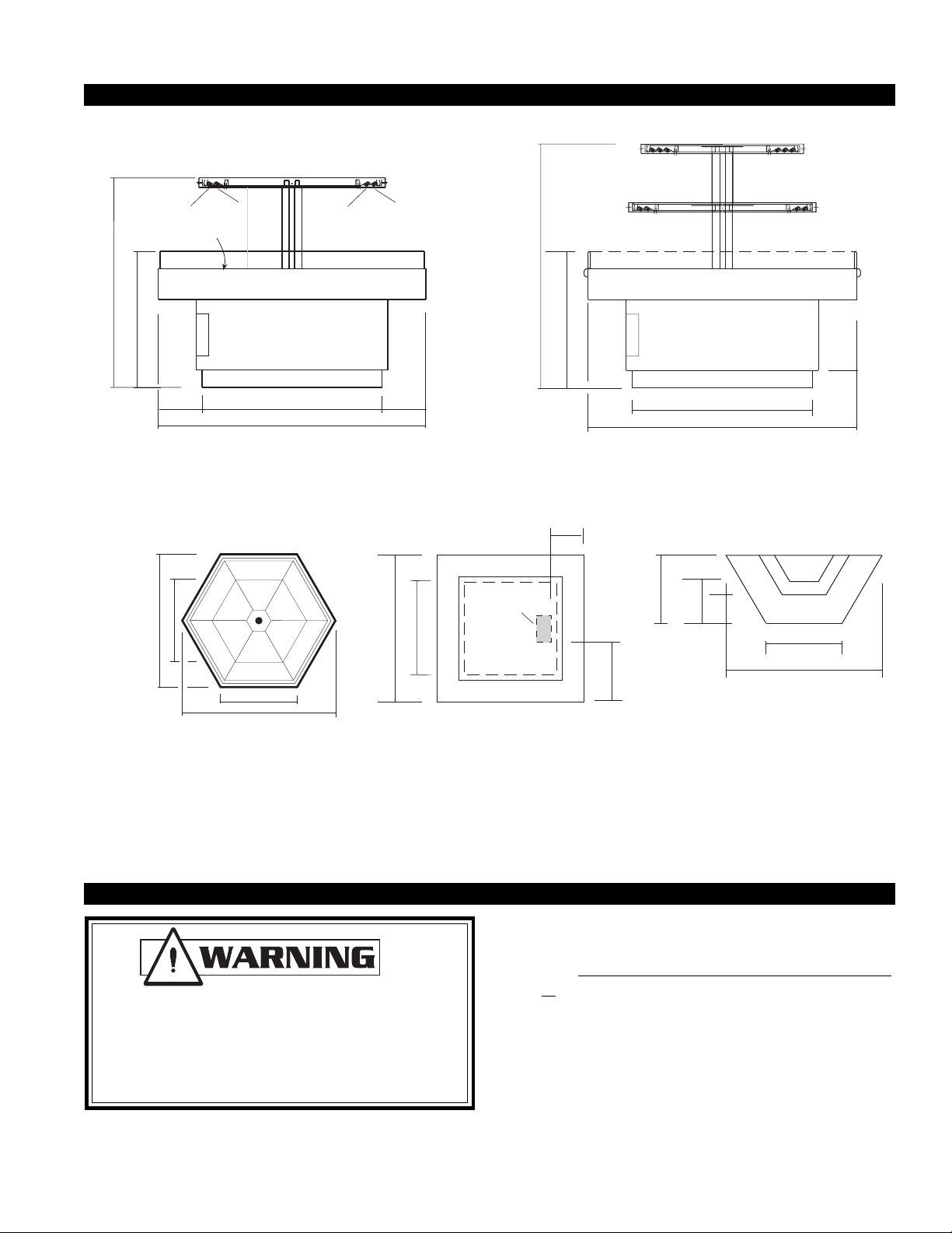
Cut & Plan Views
Food
Warmer
1
/2")
58"
Food
Warmer
12"
183/4"
a
g
rm
W
in
rid
d
le
G
"
16
/
9
"
32
16
/
1
Control
Panel
13"
1
28
/2" (191/2")
21
")
8
/
3
" (47
8
/
3
65
101/2"
")
8
/
5
" (27
4
/
3
48
1
43
/4" (251/8")
641/4" (47
1
/8")
RHR-HEX 6' & (4')
Self-Service Hot
1
(261/2")
37
/2"
7
773/8"
(54
/16")
RHR-HEX 6' & (4')
PLAN VIEW
1
10
/2"
101/2"
431/4" (25
1
/8")
1
10
/2"
541/4" (473/8")
RHR2-HEX 6' & (4')
Self-Service Hot
Scale = 1/2"
1
12
/4"
")
8
/
3
")
8
/
5
ELEC.
MECHANICAL
"
8
/
3
27"
47
STUB UP AREA
4" X 6"
" (33
16
/
" (24
11
8
/
1
23
14
"
16
/
11
20
2'-21/2" (3'-11/
4'-67/16" (6'-53/
RHR-HALF-HEX-4' (6')
Self-Service Hot
2
"
)
8
"
)
RHR SQUARE
Self Service Hot Food
IMPORTANT: It is imperative that cases
be leveled front to back and side to side
prior to joining. A level case is necessary
to ensure proper operation.
Installation
LEVELING
1. Check floor where cases are to be set to see if it's
level. Determine where the highest part of the floor
is. Cases will be shimmed off this point. Using case
blueprints, measure off and mark on floor the exact
dimensions of the case footprint. Snap chalk line for
front and back position of base rail. Mark location of
each joint front and back. Use a transit to find the
highest point along both lines. Mark the difference,
and place the appropriate number of shims required
to maintain high-point level.
3
Page 4

Electrical
IGHT-RHR, RHR2-HEX-9911
WIRING COLOR CODE
L1 BLACK
L2 ORANGE
L3 BLUE
NEUTRAL WHITE
NOTE: High Leg Connection
Orange Only
ELECTRICAL CIRCUIT IDENTIFICATION
Standard lighting for all models will be fluorescent lamps
located within the case at the top.
The switch controlling the lights and heaters are located
within an access panel on the side of the case.
BEFORE SERVICING
ALWAYS DISCONNECT ELECTRICAL
POWER AT THE MAIN DISCONNECT
WHEN SERVICING OR REPLACING ANY
ELECTRICAL COMPONENT.
This includes (but not limited to) Fans, Heat-
ers, Thermostats, and Lights.
Field wiring from the where??
Most component amperes are correctly listed in the
“Case Specs” section, but due to parts availability they
may vary slightly. Always check the serial plate for the
actual loads.
BALLAST LOCATION
Ballast
(one for each light)
Control Panel
Ballast
RHR-HEX 6' & (4')
Self-Service Hot
Ballast
(one for each light)
Ballast
FIELD WIRING & SERIAL PLATE AMPERAGE
Field Wiring must be sized for component amperes
printed on the serial plate. Actual ampere draw may be
less than specified. Field wiring from the
Control
Panel
Ballast for shelves
RHR2-HEX 6' & (4')
Self-Service Hot
Scale = 1/2"
4
Page 5

Rev.9911
User Information
FOOD HANDLING
These hot tables are for short-term holding and display
of precooked hot foods. They are not intended to cool
or reheat food. The temperature of the food should be
approximately 160°F when first put into the hot table.
Any attempt to use the hot table to display large amounts
of food for long periods of time will result in dehydrated,
overcooked and unsafe food. The quality of food will
progressively worsen as the length of time increases.
The deterioration of product quality is a function of time
and temperature. All products are affected even though
in a gravy or other liquid. They may appear to withstand
the temperature better than “dry” foods such as fried
chicken but this is not necessarily true. ALL foods will
continue to be affected by prolonged exposure to elevated temperatures.
The following guidelines are provided only as a general
guide for the use of this equipment. The local health
agency for your area can provide specific temperature
requirements.
Critical attention must be given to the heat controls for
these hot tables. Both the upper and lower heat controls must be adjusted to maintain proper food temperatures. Hot foods should be held at a minimum tem-
perature of at least 140°F (60°C) according to 1993 FDA
Food Code. However, increasing the temperature too
high will also cause the food to overcook, dry out, lose
its flavor, texture and color. Food held for prolonged
periods at high temperatures will also lose some of their
nutritional value.
All griddle type units are designed to maintain
termperatures above the FDA guideline of 140°F. This
is product temperature, not air or griddle temperature.
Due to the open design of these units, they must be
loaded with product for proper operation. When units
are empty, they experience rapid rise of heated air from
air outside the case. This action gives empty units a false,
lower than desired, temperature reading. Loading the
case traps the air at the griddle, raising temperatures
to the 165°F to 185°F range, keeping product well above
the FDA guidelines. Remember, these units must be
loaded with product to maintain safe product temperature.
Different foods will require different control settings.
The type of food, the quantities of food and length of
time that it is to remain in the hot table must be considered when establishing control settings. Therefore,
it must be the user’s responsibility to establish the
correct control settings to maintain the food at the
safest, tastiest and most saleable condition.
FOOD TEMPERATURES CAN BE
ACCURATELY DETERMINED ONLY
THROUGH THE USE OF FOOD
THERMOMETERS!
IMPORTANT OPERATION TIPS:
*Preheat case 30 minutes before loading product
using higher settings.
Using thermometer, check product before
*
loading in case (150°-160°).
* At start, set lamps to "3". After loading, recheck
temperature every 1/2 hour to see that unit is
operating properly. Adjust the thermostat (a higher
number for hotter and a lower number for cooler)
+
to maintain product temperature of 140°F
(60°C
minimum. The setting will depend on the type of
product being displayed Be sure to test product
temperature with a thermometer frequently for
good product maintenance.
*Food should maintain contact directly with the
"griddle" at all times.
CONTROLS
There are three sets of controls for the hex case, each
behind its own access panel located on the side of the
case. The dial with the numbered settings is for the
griddle. The other dials / switches are for the overhead
lights and heating components.
OVERHEAD HEATING SYSTEM
Cal rod units are located above the griddles to provide
top heat. To obtain the proper food temperatures,
they must be adjusted. Settings may vary depending on food composition. Maximum limits
should be avoided to prevent overcooking or drying out food.
CARE AND CLEANING
Long life and satisfactory performance of any equipment
is dependent upon the care it receives. With this in mind,
all of the exposed work surfaces of these hot tables have
been made entirely of easy to clean stainless steel.
Stainless steel is one of the easiest materials to clean
and keep clean. Normally it is just a matter of wiping
spills off the surface when they happen followed by a
thorough cleaning with soap and water at the end of the
day. Frequent and regular cleaning will prevent the
.
)
5
Page 6
User Information (Continued)
buildup of baked on difficult to remove spills. Many types
of cleansers are available and safe to use on stainless
steel. However, ordinary steel wool and steel brushes
should not be used. Small particles of the steel may
become imbedded into the stainless steel surfaces that
will eventually rust and stain.
GENERAL CLEANING RULES
1. ALLOW SURFACES TO COOL BEFORE HANDLING
2. Clean frequently and regularly
3. Rinse thoroughly after cleaning
4. Remove surface spills immediately with a damp
cloth
CLEANING INSTRUCTIONS
1. Turn temperature control knobs to OFF position.
2. Allow unit to cool completely.
3. Wipe entire unit with clean cloth and mild detergent.
The EXTERIOR surfaces of these hot tables must be
cleaned with a mild detergent and warm water to protect and maintain their attractive finish. Never use abrasive cleaners or scouring pads.
TO REMOVE “BAKED-ON” SPLATTER, GREASE OR LIGHT
DISCOLORATION TO STAINLESS STEEL
CLEANSING AGENT APPLICATION
Grade F Italian Pumice ............. Scour or rub with damp cloth
Liquid NuSteel ............................ Scour with small amount on
dry cloth
Paste NuSteel
Household Cleansers ............... Rub with damp cloth
Coopers Stainless Steel Cleaner
Allen Stainless Steel Polish
TO REMOVE HEAT TINT OR HEAVY DISCOLORATION
CLEANSING AGENT APPLICATION
Allen Stainless Steel Polish......Small amount on damp cloth
Birdsall “Staybright” .................. Rub with damp cloth
Wyandotte
Bab-O
Nusteel ......................................... Rub with stainless steel wool
IGHT-RHR, RHR2-HEX-9911
PLEXIGLASS & ACRYLIC CARE
CLEANING
Clean with plenty of nonabrasive soap (or detergent)
and lukewarm water, using the bare hand to feel and
dislodge any caked-on dirt. A soft, grit-free cloth, sponge,
or chamois may be used, but only as a means of carrying the water to the plastic. Dry with a clean damp
chamois or clean soft cloth such as cotton flannel. Hard,
rough cloths or paper towels will scratch the acrylic,
and should not be used.
WAXING
If after removing dirt and grease, the acrylic can be waxed
with a good grade commercial wax. This will improve
the appearance of the surface by filling in most minor
scratches. Wax should be applied in a thin even coat, and
brought to a high polish by rubbing lightly with a dry clean
soft cloth, such as a cotton flannel. Excessive rubbing
may cause scratching and/or buildup an electrostatic
charge, which attracts dust and dirt to the surface. Blotting with a clean damp cloth is recommended to remove
charge.
ANTISTATIC COATINGS
For acrylic used indoors, antistatic coatings successfully
prevent the accumulation of electrostatic charge for
periods of several months, if the surface is not washed
or wiped down with a wet cloth. Between applications
of the antistatic coatings, the parts need only be dusted
with a soft clean cloth to maintain a good appearance.
In use, liquid antistatic coatings should be applied in a
very thin even coat. If beads appear as it is applied, the
coat is too thick and the excess should be removed with
another cloth. Allow the coating to dry, then bring to
a high gloss with a soft cloth.
CLEANING PRECAUTIONS
To preserve the attractive finish, use warm water and
a mild detergent to wash the exterior of the cases. DO
NOT USE ABRASIVE CLEANERS OR STEEL
WOOL SCOURING PADS as these will mar the
surface.
6
Page 7

Rev.9911
ALWAYS DISCONNECT ELECTRICAL POWER AT THE MAIN DISCONNECT WHEN SERVICING OR
REPLACING ANY ELECTRICAL
COMPONENT. This includes (but
not limited to) Fans, Heaters,
Thermostats, and Lights.
REPLACING OVERHEAD HEAT LAMPS
Overhead Halogen and Merco lamps are designed to
last through many hours of use. Should there be a need
to replace one, it is as simple as replacing a standard
fluorescent light bulb.
The Heat lamps used in these cases get EXTREMELY
HOT! NEVER touch a lamp until the case has had ample
time to cool down! It is also highly recommended to
handle lamps with gloves or use a cloth rag - not just
for the heat factor, but also the oils in your fingers will
drastically shorten the life of the lamp.
1. Turn light switch to OFF before replacing any
lighting components.
2. Disconnect light fixture by removing power cord
Maintenance
from socket in the right rear interior corner of the
merchandiser.
3. Place the shelf on a flat surface to remove the clear
plastic protective shield from the fixture. Carefully
insert one finger between the fixture socket and the
protective shield. Use other hand to "pinch" lens
cover (and simultaneously hold the fixture in place)
while lifting with inserted finger. When shield
separates from fixture at one end, remove it by
SLOWLY pulling remainder of shield away from
fixture.
4. Remove lamp by depressing spring loaded socket at
end of fixture, and swinging opposite end of lamp
from it's former position.
5. Using gloves or covering for lamp, insert new lamp
into spring loaded socket, depressing socket until
opposite end of lamp properly enters stationary
light socket.
6. Return lamp to original position by lightly pinching it
in from each side, and inserting shield flanges into
fixture channel. Continue process along length of
lamp shield until it is in it's final proper position.
7. Return lamp to original position by lightly pinching it
in from each side, and inserting shield flanges into
fixture channel. Continue process along length of
lamp shield until it is in it's final proper position.
7
Page 8

IGHT-RHR, RHR2-HEX-9911
Case Specifications
MODEL LENGTH WELLS GRIDDLES SHELVES VOLTS PHASE Loads PHASE Loads
# OF # OF # OF CIRCUIT 1 CIRCUIT 2
RHR-HEX
4'-0" –– 1 — 208 1Ø 17
240 1Ø 19
6'-0" –– 1 — 208 3Ø 21
240 3Ø 24
RHR-HEX-2
4'-0" –– 2 1 208 1Ø 16
240 1Ø 18
6'-0" –– 2 1 208 3Ø 23
240 3Ø 27
RHR-Square
4'-0" –– 1 — 208 1Ø 18
240 1Ø 18
6'-0" –– 1 — 208 Pending Design
240 Pending Design
RHR-1/2 HEX
4'-0" –– 1 208 1Ø 9
240 1Ø 10
6'-0" –– 1 208 1Ø 17
NOTES: These merchandisers have been designed for use in stores where temperatures and humidity are maintained at or below 75°F and 55%RH. Stores are
responsible for setting their cases appropriately in conditions which vary from the above. The number of defrosts and/or the duration may vary for cases
displaying products for which they were not designed. Italicized data indicates optional equipment.
•Hussmann Chino reserves the right to change or revise case specifications and design in connection with any feature of our products. Such changes do not entitle
the buyer to corresponding changes, improvements, additions, or replacement of equipment previously sold or shipped. These changes may also affect the loads
applicable to a particular case, therefore always check the serial plate at the back of the case and/or consult the factory for the current loads for your particular
equipment.
INQUIRIES? Technical (800) 395-9229 X2133 Service (800) 395-2320 Parts and Warranty Information (800) 395-9229 X2131
HUSSMANN CHINO CASE SPECIFICATIONS 11/99
240 1Ø 19
8
Page 9

Rev.9911
Sheet
1 of 1
X
BK
Boris Kasrel
Date:
Pro ject Title:
Drawing N o.:
Drawn By:
Next A ssembly:
Drawing Title:
Date:
Hussmann
Corp oratio n
137 70 Ramona
Avenue
Chi no , C A . 91710
(909)- 590- 491 0
Lic.#: 64440 6
Revisions:
No.
Descripti on:
Checked By:
By:
7
3
P1
5
12
4
6
P
H2
L2
L1
H1
L
White
White
Red
White
White
Red
White
White
Red
White
White
Red
White
White
Red
White
White
Red
L
Gr iddle
(6 ) 206W/220VACFlexible Heater P ad # 225-01 -6770/-6770T
Overhead Heating Element
HE- 04-68" #125-01-3235
2700 W/ 240 VAC
Bulb
Sensor
Te m p.Contr o l
Pi l o t L ig h t
Pil ot Li ght
Electr onic T-Stat
Overhead Lighting
(6 ) F 13 D BX2 3T4/SPX35
Fl uo re s ce nt Double Biax Lamps
Ballast4111F2 RP
s
L1
L2
N
G
PO W ER
# 125-01-031 1
Overhead
Ballast Cooling
M
L3
Con ta ct or
# 125-001-10 01
Ligh ts
#125-01-03 11
#225-01-3301A
NG
T- 11S11T444
On-183ºF
Off-2 1 0ºF
N
ote:
Case M
UST be grounded
RHR-Hex-4' basic,
ledge lightsare optional.
RHR Hex 4' Case Wi ring
~20
8
/
2
4
0
V
- 1
Ø
- 6
0Hz
LOADIN G
208 V 240 V
L1
L2
L3
15.1
16.8
17.4
19.1
W6100001
10/22/99
rhrhex Standard
Wiring Schematics
9
Page 10

Sheet 1
of 1
X
Boris Kasrel/AEC
Date:
Pro ject Title:
Drawing N
o.:
Drawn By:
Next A ssembly:
Drawing Title:
Date:
Hussmann Corp oratio n
137 70 Ramona Avenue
Chi no , C A
. 91710
(909)- 590- 491 0
Lic.#: 64440
6
Revisions:
No. Descripti on:
Checked By:
By:
BK
7
3
P1
5
12
4
6
P
H2
L2
L1
H1
L
White
White
Red
White
White
Red
White
White
Red
White
White
Red
White
White
Red
White
White
Red
L
Gri ddl e Heater s Pads
(2) sets of 3 p ad s - 451 W / 220 VAC
Overhead H eating
El em ent
Bulb
S ensor
Temp. Control
#225-01-3301
NG T- 1 1S 11T444
On-
183ºF /Off-2 10ºF
Light s
1 25-01-0311
Overhead Lights
(6) F13D BX 23
T4/SPX 35
Fl
uorescent D ouble Biax Lamps
Overhead
Ballast Cooli
ng
(2) 2500 W / 240 VAC
M
s
L1
L2
L3
N
G
Po w er S wi tch
1 25-01-0311
Pil ot Li ght
Pil ot Li ght
El ectr o nic T- S ta t
SPDT Rel ay
225-0
1- 2045
(6) Ball ast 4 11 1F 2RP
208 / 240 VAC - 3 Ø - 60z
R
HR Hex 5'6" Wi
r ing D iag ram
RHR-Hex-5'6"
250 0W t Split Overhead He ater.
L OADIN G
208 V 240 V
L1
L2
L3
20.6
20.6
19.7
23.8
23.8
22.5
10/22/9
W6100002
IGHT-RHR, RHR2-HEX-9911
Wiring Schematics
10
Page 11

Rev.9911
Sheet 1 of 1
X
BK
Boris Kasrel
Date:
Pro ject Title:
Drawing N o.:
Drawn By:
Next A ssembly:
Drawing Title:
Date:
Hussmann
Corp oratio n
137 70 Ramona
Avenue
Chi no , C A . 91710
(909)- 590- 491 0
Lic.#: 64440 6
Revisions:
No.
Descripti on:
Checked By:
By:
7
3
P1
512 4 6
P
H2
L2
L1
H1
L
L
Gridd le
(2) s ets o f 3pads - 20 6 W / 2 20 VAC
Bulb
Sensor
Temp. Co ntrol
Pi lot Lig ht
Pi lot Lig ht
Electro nic T- St at
Shelf I n stal lat ion
(6) F1 3DBX 2 3T 4/SPX 35
Fluor esc e nt D o uble Biax Lamps
(6) B
al last 4 1 11F 2RP
Co ntrol Box I nstal lat ion
White
White
Red
White
White
Red
White
White
Red
White
White
Red
White
White
Red
White
White
Red
Cal- Rod 980W /~240V
Cal -Rod 1200W / ~240V
Infinite
Co ntrol
P
H2
L2
L1
H1
L
Pi lot Lig
ht
O
verhead (cr o wn ) In stal lat ion
(3) F1 3DBX 2 3T 4/ SPX 35
Fluor esc e nt D o uble Biax Lamps
Bal last 4 1 11F 2RP
Infinite
Co ntrol
M
Overhead
Ballast Cooling
PO W ER
#125-0 1-0 3 11
s
L1
L2
L3
N
G
LIGH T S
#125-01-0 3 11
#2 25 -01- 33 01A
NGT 11S11
T444
Safety T-St
at
O
N: 18 3 °F
OFF:210°F
#2 25 -01- 00 76
NGT 11S31T
44 4
Colu m n H ea
t Li mi t
ON:
98 .6°F
OFF : 80.6°F
Note: Case M UST be grounded
RHR -Hex 4' w /shel f C ase Wir ing
RHR - Hex 4' Shelf Unit
LOADIN G
208 V 240 V
L1
L2
L3
16.0
13.1
18.1
14.6
10/22/99
W6100003
rhr-hex 2 level
11
Page 12

Sheet 1
of 1
X
AEC/BK
Adrian E.Crisci /
Boris Kasrel
Date:
Project Title:
Drawing No.:
Drawn By:
NextAssembly:
Drawing Title:
Date:
Hussmann
Corporation
13770 RamonaAvenue
Chino, CA. 91710
(909)-590-4910
Lic.#: 644406
Revisions:
No.
Description:
Checked By:
By:
7
3
P1
512 4 6
P
H2
L2
L1
H1
L
L
Griddle
(2) sets of 3 flexiable heating pads - 451 W / 220 VAC ea.
Bulb
Sen
sor
Temp.C ontrol
Pilot Light
Electronic
T-Stat
Lights
(6) F13DBX23T4/SPX35
Fluorescent Double Biax Lamps
(6) Ballast 4111F2RP
Control Box Location
White
White
Red
White
White
Red
White
White
Red
White
White
Red
White
White
Red
White
White
Red
Infinite
Control
P
H2
L2
L1
H1
L
Cal-Rod 125-01-1006
980 / 240VACr
Inner Htr
Overhead (crown ) Installation
(6) F13DBX23T4/SPX35
Fluorescent Double Biax Lamps
Infinite
Control
MM
(6) Ballast 4111F2RP
Overhead Location
Overhead
Ballast Cooling
Shelf I
nstalation
Cal-Rod 125-01-3247
2250W / 240VAC
Outer Htr
Cal-Rod 125-01-3246
1850Wt / 240VAC
L1
L2
N
L3
G
L1
L2
N
L3
S
G
L1
L2
N
L3
G
L1
L2
N
L3
Contactor
125-01-1001
G
Power
Black
White
Lights
Pilot
Light
#225-01-007
6
NGT11S31T4444
Cloumn Heat Limit
ON: 98.6 °F
OFF: 80.6°F
#225-01-33
01A
NGT 11S11T444
Safety T-Stat
ON: 183°F
OFF: 210°F
Note: Case MUST be grounded
RHR Hex 5'-6"Case Wiring Diagram
Model with shelf unit
LOADING
208 V 240 V
L1
L2
L3
21.7
23.3
18.5
24.5
27.0
21.2
W6100004
10/22/99
Wiring Schematics
IGHT-RHR, RHR2-HEX-9911
12
Page 13

Rev.9911
Sheet ____ of ___ _
X
AEC
Adrian E. Crisci
Date:
Pro ject Title:
Drawing N o.:
Drawn By:
Next A ssembly:
Drawing Title:
Date:
Hussmann
Corp oratio n
137 70 Ramona
Avenue
Chi no , C A . 91710
(909)- 590- 491 0
Lic.#: 64440 6
Revisions:
No.
Descripti on:
Checked By:
By:
7
3
P1
5
12
4
6
P
H2
L2
L1
H1
L
L
Light s
1 25-01-0311
Over head
B all
ast C ooling
M
s
L1
L2
L3
N
G
Po w er S wi tc h
1 25-01-0311
Pil ot Li g ht
El ectr
onic T- Stat
Temp. Control
Bulb
S ens
or
Pil
ot Light
(8) Ball a st 4111F2RP
Overhead Lights
Fl uor esc ent Double Biax Lamps
(8) F1 3D BX 23T4/SPX 35
Overhea
d Heating
El em ent
3550 W @ 240VAC
Gri d dle H eater s
(4) 36 4 W@220
VAC
Part# 225- 01- 33 01A
T- S t a t S a f e ty
NG T 11S11T444
ON : 183°F
O FF:
210°F
L OADIN G
208 V 240 V
L1
L2
L3
22.4
19.0
25.4
22.0
11
RHR HE X 4 x 4 Square case
10/22/99
W6100005
Rhr Square
Wiring Schematics
13
Page 14

Design pending
IGHT-RHR, RHR2-HEX-9911
Wiring Schematics
14
Page 15

Rev.9911
Sheet 1 of 1
X
Boris Kasrel
Date:
Pro ject Title:
Drawing N o.:
Drawn By:
Next A ssembly:
Drawing Title:
Date:
Hussmann
Corp oratio n
137 70 Ramona
Avenue
Chi no , C A . 91710
(909)- 590- 491 0
Lic.#: 64440 6
Revisions:
No.
Descripti on:
Checked By:
By:
BK
7
3
P1
5
12
4
6
P
H2
L2
L1
H1
L
White
White
Red
White
White
Red
White
White
Red
B
B
B
Pilot
Li ght
Temp Contr ol
Bulb
(3) He at er Pad 206 W / 220
VAC 225-01-6770 / ...-6 770T
Grid dl e
HE-07#125-01-3242
Overhead I nst allati o n
(3) Co m pact D ou bleBiaxLamps
F13D BX23 T 4/SPX35
Infi nit e
Co ntr ol
Pilot
Li ght
L
El ectro nic
T- S t at
Ballast
4111F2R P
208 / 240 VAC - 1 Ø - 5 0 / 60 Hz
Over head
Ballast C oolin g
M
L1
L2
N
G
L
3
Power
125-01-0311
Light s
125-01 -0311
Cal-Ro d Htr 1 250 W / 240 VAC
DPSTRelay, 25A
12
5-01-3182
#225-01-3301A
NG T 11S11T444
Safety Lim it
ON: 183 °F
OFF: 21 0°F
RHR HE X - 4'/ Hal f Case
Fl r Lamps, Contactor
Note: Case M UST be grounded
LOADIN G
208 V 240 V
L1
L2
L3
9.0
7.2
10.2
8.3
10/22/99
W6100007
Rhr 1/2 Hex
Wiring Schematics
15
Page 16

IGHT-RHR, RHR2-HEX-9911
Sheet 1 of 1
final
Boris Kasre
Date:
Pro ject Title:
Drawing N o.:
Drawn By:
Next A ssembly:
Drawing Title:
Date:
Hussmann
Corp oratio n
137 70 Ramona Avenue
Chi no , C A . 91710
(909)- 590- 491 0
Lic.#: 64440 6
Revisions:
No.
Descripti on:
Checked By:
By:
BK
7
3
P1
5
12
4
6
P
H2
L2
L1
H1
L
L
Gri ddle H eat ers P ads
(2) sets of 3 pads - 451 W / 220 VAC
Over head H eating
El em ent
Bulb
S ensor
Temp. Control
Pil ot Li gh t
Pil ot Li gh t
El e
ctr oni c T- St at
Light s
1 25-01-0311
Overhea
dLights
(6) F
13DBX23T4/SPX35
Fl
uorescent D ouble Biax Lamps
(6) Ball a st 4 11 1F 2RP
O
ver head
Ballast Cooling
(2) 25
00 W / 240 VAC
M
s
L1
L2
L3
N
G
Po w er S wi tch
1 25-01-0311
White
White
Red
White
White
Red
White
White
Red
#225- 01-3301A
NG T
11S11T444
Safety Limit
ON
:183°F
O FF: 210°F
208 / 240 V AC - 1Ø - 50 / 60z.
RHR Hex 5'6" 1/2 Case Wi ring
RHR-Hex-5'6" 1/2 C ase
LOADIN G
208 V 240 V
L1
L2
L3
14.8
16.5
17.1
18.8
10/22/99
W6100008
Note: Case must be grounded
16
Page 17

Rev.9911
Appendices
APPENDIX A. – Temperature Guidelines
1.0 Hot cases are tested to maintain all hot food at 140° - 150°.
These cases are not designed to heat up or cook food. It is the
user’s responsibility to stock the hot food cases immediately after
the cooking of the food with a pulp temperature of at least 150°
to 160°.
All griddle type units are designed to maintain
termperatures above the FDA guideline of 140°F.
This is product temperature, not air or griddle
temperature. Due to the open design of these units,
they must be loaded with product for proper operation. When units are empty, they experience rapid
rise of heated air from air outside the case. This
action gives empty units a false, lower than desired,
temperature reading. Loading the case traps the air
at the griddle, raising temperatures to the 165°F to
185°F range, keeping product well above the FDA
guidelines. Remember, these units must be loaded
with product to maintain safe product tempera
APPENDIX B. – Application Recommendations
1.0
The installer should perform a complete start-up evaluation prior to the
loading of food into the hot food case, which includes such items as:
a) Initial temperature performance, Griddles and Hot Wells.
b) Observation of outside influences such as drafts, radiant heating
from the ceiling and from lamps. Such influence should be
properly corrected or compensated for.
c) Complete start-up procedures should include :
1. Heat / display lamps are lighting
2. Indicator lamps on control panel(s) are working
3. Auto-fill is functioning properly (Service cases)
4. Hot Griddles are functioning.
APPENDIX C. – Field Recommendations -
1.0 The most consistent indicator of display hot case performance is
temperature of the product itself.
NOTE: Public Health will use the temperature of the product in
determining if the hot case will be allowed to display potentially
hazardous food. For the purpose of this evaluation, product
temperature above the FDA Food Code 1993 temperature for
potentially hazardous food will be the first indication that an evaluation
should be performed. It is expected that all hot cases will keep food
at the FDA Food Code 1993 temperature to prevent the sale of
potentially hazardous food.
1.1 The following recommendations are made for the purpose of
arriving at easily taken and understood data which, coupled with
other observations, may be used to determined whether a display
refrigerator is working as intended:
a) INSTRUMENT – A stainless steel stem-type thermometer is
recommended and it should have a dial a minimum of 1 inch
internal diameter. A test thermometer scaled only in Celsius or
dually scaled in Celsius and Fahrenheit shall be accurate to
1°C (1.8°F). Temperature measuring devices that are scaled
only in Fahrenheit shall be accurate to 2°F. The thermometer
should be checked for proper calibration. (It should read 32°F
when the stem is immersed in an ice water bath).
b) LOCATION – The thermometer must be inserted into the food
itself to acquire proper food pulp temperature.
c) READING – The thermometer reading should be made only
after it has been allowed to stabilize, i.e., maintain a constant
reading.
Loading Product: Cases should be allowed to heat up for one
hour before product is loaded.
Temperature adjustments: Allow 4 hours after adjustment has
been made before testing pulp temperature of product.
d) OTHER OBSERVATIONS – Other observations should be made
which may indicate operating problems, such as unsatisfactory
product, feel/appearance.
APPENDIX D. – Recommendations to user -
1.0 The manufacturer should provide instructions and recommendations
for proper periodic cleaning. The user will be responsible for such
cleaning, including the cleaning of equipment within the compartment and the hot area(s). Cleaning practices, particularly with respect
to proper refrigerator unloading and warm-up, must be in
accordance with applicable recommendations.
1. Allow the case to preheat for one hour prior to loading.
2. Hot foods should enter the case directly after cooking or no
lower than 150° - 160°F. The Hot Cases are not designed to
heat up or cook food.
3. Self Service - be sure to display product in single layer in
direct contact with heating surface.
4. All griddle type units are designed to maintain
termperatures above the FDA guideline of 140°F.
This is product temperature, not air or griddle
temperature. Due to the open design of these
units, they must be loaded with product for
proper operation. When units are empty, they
experience rapid rise of heated air from air
outside the case. This action gives empty units a
false, lower than desired, temperature reading.
Loading the case traps the air at the griddle,
raising temperatures to the 165°F to 185°F range,
keeping product well above the FDA guidelines.
Remember, these units must be loaded with
product to maintain safe product temperature.
5. Check the food pulp temperature frequently with a thermometer to make sure it is at the proper holding temperature. Hot
foods should be at 140°. The thermometer must be inserted
into the food itself for the proper temperature.
17
Page 18

6. Do not display more food than will be sold within a 4 hour
period.
7. When restocking, bring older food to the front, and stock
fresher food on top.
8. Clean spills as soon as they happen.
9. Fingerprints and food splatter will drastically shorten bulb life.
Clean splatter off the bulbs immediately with a soft cloth.
When handling bulbs, wear cotton gloves or use a cotton rag /
towel.
10. When “freshening” foods such as macaroni and cheese with
added water, heat the water in a clean container until it is
10° to 20°F above the desired holding temperature of the
food. This will keep the food at a safe serving temperature.
Depending on the amount of water, the temperature can drop
10° to 20° in as little as five minutes.
11. When transferring hot foods in the heated merchandiser to
clean pans, preheat the clean pan. Transferring hot foods to
room temperature pans can cause the temperature of the food
to drop 20° or more thus causing food to be at an unsafe
serving temperature.
12. Clean spills as they happen simply by wiping with a cloth. Be
sure to use a dry cloth on very hot surfaces to prevent steam
burns.
13. Turn the equipment off and allow to cool before cleaning.
14. To remove “baked-on” splatter from Stainless Steel, the
following may be used
Grade F Italian Pumice Scour or rub with a damp cloth
Liquid Nusteel Scour with a small amount of a dry
cloth
Paste NuSteel
Household Cleaners Rub with a damp cloth
Coopers Stainless Steel Cleaner
Allen Stainless Steel Polish
IGHT-RHR, RHR2-HEX-9911
18
Page 19

Rev.9911
Limited Warranty
This warranty is made to the original user at the original installation site and is not transferable.
Hussmann merchandisers are warranted to be free from defect in material and workmanship under normal use and
service for a period of one (1) year from the date of original installation (not to exceed fifteen (15) months from the date of
shipment for the factory). Hussmann Impact
the above criteria. Hussmann’s obligation under this warranty shall be limited to repairing or exchanging any part or parts,
without charge F.O.B. factory or nearest authorized parts depot within said period and which is proven to the satisfaction of
the original manufacturing plant warranty group to be thus defective.
Hussmann covers the entire case or refrigeration product and all its components (except for lamps, driers, fuses, and
other maintenance type replacement parts) for the one (1) year warranty period.
Additionally, Hussmann warrants for a total period of three (3) years all sealed, multi-glass assemblies except those
used in sliding doors on closed meat display cases. If within three (3) years from the date of installation (not to exceed thirtynine (39) months from the date of shipment from factory), it shall be proven to the satisfaction of the originating factory
warranty group that there is impaired visibility through the multi-glass assemblies thereof caused by moisture between the
glasses, the multi-glass assembly will be replaced free of charge, F.O.B. factory. This additional warranty excludes accident,
misuse, or glass breakage.
On Hussmann manufactured self-contained display cases, Hussmann agrees to repair or exchange, at its option, the
original motor/compressor unit only with a motor/compressor of like or of similar design and capacity if it is shown to the
satisfaction of Hussmann that the motor/compressor is inoperative due to defects in factory workmanship or material under
normal use and service as outlined in Hussmann’s “Installation Instructions” which are shipped inside new Hussmann equipment. Hussmann’s sole obligation under this warranty shall be limited to a period not to exceed five years from date of
factory shipment.
On Hussmann refrigeration systems, an additional (4) year extended warranty for the motor/compressor assembly
is available, but must be purchased prior to shipment to be in effect. Hussmann reserves the right to inspect the job site,
installation and reason for failure.
The motor/compressor warranties listed above do not include replacement or repair of controls, relays, capacitors,
overload protectors, valve plates, oil pumps, gaskets or any external part on the motor/compressor replaceable in the field, or
any other part of the refrigeration system or self-contained display case.
THE WARRANTIES TO REPAIR OR REPLACE ABOVE RECITED ARE THE ONLY WARRANTIES, EXPRESS, IMPLIED OR STATUTORY, MADE BY HUSSMANN WITH RESPECT TO THE ABOVE MENTIONED EQUIPMENT, INCLUDING ANY IMPLIED WARRANTY OF MERCHANTABILITY OR FITNESS, AND HUSSMANN NEITHER ASSUMES NOR
AUTHORIZES ANY PERSON TO ASSUME FOR IT, ANY OTHER OBLIGATION OR LIABILITY IN CONNECTION WITH
THE SALE OF SAID EQUIPMENT OR ANY PART THEREOF.
THIS WARRANTY SHALL NOT APPLY TO LOSS OF FOOD OR CONTENTS OF THE EQUIPMENT DUE
TO FAILURE FOR ANY REASON. HUSSMANN SHALL NOT BE LIABLE:
•For payment of labor for any removal or installation of warranted parts;
•For any repair or replacements made without the written consent of Hussmann, or when the equipment is installed or
operated in a manner contrary to the printed instructions covering installation and service which accompanied such
equipment;
•For any damages, delays, or losses, direct or consequential which may arise in connection with such equipment or part
thereof;
•For damages caused by fire, flood, strikes, acts of God or circumstances beyond its control;
•When the equipment is subject to negligence, abuse, misuse or when the serial number of the equipment has been
removed, defaced, or altered;
•When the equipment is operated on low or improper voltages
•When the equipment is put to a use other than normally recommended by Hussmann (i.e. deli case used for fresh
meat);
•When operation of this equipment is impaired due to improper drain installation;
•For payment of refrigerant loss for any reason;
•For costs related to shipping or handling of replacement parts.
Hussmann Corporation, Corporate Headquarters: Bridgeton, Missouri, U.S.A. 63044 August 1, 1998
Modular Coils are warranted for a total of five (5) years based upon
19
Page 20

IGHT-RHR, RHR2-HEX-9911
Service Record
Last service date: By:
/Chino
Additional copies of this publication may be obtained by contacting:
Hussmann® Chino
13770 Ramona Avenue • Chino, California 91710
(909) 628-8942 FAX
(909) 590-4910
(800) 395-9229
The MODEL NAME and SERIAL NUMBER is required in order to provide you
with the correct parts and information for your particular unit.
They can be found on a small metal plate on the unit.
Please note them below for future reference.
MODEL:
SERIAL NUMBER:
20
 Loading...