


Operating and Installation
Instructions
MODEL: GSVM – Self Contained Medium
Temperature Cases for Dairy,
Beverages, and Deli Products
OII - GSVM
January 2005
TABLE OF CONTENTS |
|
|
Page |
Introduction |
4 |
Inspection |
4 |
Location and Clearance |
4 |
Skid |
4 |
Leveling |
5 |
Sealing |
5 |
Access Panel Removal |
5 |
Legs |
5 |
Serial Plate |
5 |
Air distribution and Product Loading |
6 |
Power Requirements |
6 |
Electrical Box |
6 |
Power Switch |
6 |
Defrost Time Clock |
6 & 7 |
Connections |
7 |
Drains |
7 & 10 |
Dimensions |
8 |
Electrical |
8 |
BTU Capacity |
8 |
Shelving Maximum Weight Capacities |
8 & 9 |
Temperature Control |
9 |
Condensing Unit |
10 |
Shelves |
10 |
Thermometer |
10 |
Lighting |
10 |
Light Switches |
10 |
Ballasts |
11 |
Cleaning Exterior, Interior, Stainless Steel Surfaces |
11 |
2
TABLE OF CONTENTS CON’T |
|
|
Page |
Refrigeration |
11 |
Leak Testing |
12 |
Evacuation |
12 |
Temperature Control |
13 |
Evaporator Fan Motors |
13 |
Trouble Shooting Charts |
14 – 16 |
GSVM Accessories |
16 – 17 |
Warranty and Parts Information |
17 |
Wiring Diagrams |
18 – 21 |
This GSVM case was manufactured in Gloversville, New York. Our phone #’s are (518) 725-0644 for New York State residents and our toll free #800-753-7790 for outside New York – should you have further questions.
3
INTRODUCTION –
The Hussmann Model GSVM open vertical merchandiser offers versatility in the display of medium temperature (3541ºF) products such as diary products, prepared salads, pizza and fresh entrees that are pre-chilled in a cooler.
So that you can realize maximum benefit from this fine piece of equipment we urge both you and your installer to carefully read and follow this brief set of instructions prior to installation of the equipment.
INSPECTION –
The equipment has been skidded and crated prior to shipment from the factory. It is the carrier’s responsibility to deliver it to you in good condition until such time as you sign for it.
Upon receipt of the cabinet, examine the packaging for damage. If the packaging is damaged, make specific notation on the delivery ticket as to the location and extent of damage prior to signing for the piece.
Carefully remove packaging and examine the cabinet for damage. If damage is found, contact the delivering carrier immediately and request that his agent prepare an inspection report for the purpose of filing a claim. THIS IS YOUR RESPONSIBILITY, NOT THE FACTORY’S.
Save all packaging materials and move the cabinet as little as possible prior to inspection.
LOCATION and CLEARANCE –
It is important that careful consideration be given to locating the cabinet away from an area where direct sunlight would shine into the fixture, or where drafts from air conditioning grilles, fans, and open doors could affect its operation.
The GSVM4060 and 4072 have front condenser air intake and discharge. A minimum distance of two feet must be left open in front of the case so that air discharge and intake to the condensing unit is not obstructed.
The GSVM5272 model requires a 5" minimum clearance behind the case and clear above the case since it has straight through condenser air flow. Brackets are provided for field attachment to obtain the 5" spacing.
SKID –
The skid should be left on the cabinet until it is near its final location. The skid provides protection for both case and floor.
The skid is removed by raising one end of the case approx. 6", block securely and remove the 2 skid bolts on the raised end – then screw back into the holes 2 leg levelers.
4

The procedure is repeated on the opposite end. When the leg levelers are in place, the case may be slid off the skid and placed in its final location.
LEVELING –
The cabinet must be leveled properly to insure full drainage of condensate water from the evaporator coil. Level the case from front to rear and end to end. Standard levelers, packed inside the case, or optional legs can be provided for this purpose.
SEALING –
Once the case is properly leveled, the case should be sealed to the floor as shown in the following drawing, using an NSF approved material such as General Electric RTV-102 silicone sealer or equivalent.
Silicone Sealant
Floor
ACCESS PANEL REMOVAL –
The louvered access panel on the lower front of the case provides access to the condensing unit, electrical box and condensate pan. Remove panel by removing screw at bottom and lifting up and pulling forward.
DRAINS –
Remote draining is not required in self-contained models. The condensate water from the evaporator drains out through the bottom of the cabinet, through a copper trap attached to the underside and into the condensing unit compartment to a heated condensate pan.
Until this trap gets filled with water from the initial defrost, there may be a small frost buildup in the coil area on startup, which should disappear after the first defrost. The pan uses a thermistor to sense the presence of water in the pan and adjusts the amount of heat required to evaporate the water.
LEGS (OPTIONAL) -
If required by Health Inspectors the levelers can be removed and replaced with NSF Approved legs to raise the case 6 inches for cleaning purposes. An optional skirt kit can be provided to clip on to the legs.
SERIAL PLATE –
The serial plate is located on the interior top wall of the cabinet towards the left end. It contains all pertinent information such as model, cabinet serial number, amperage rating, refrigerant type and charge, etc. This information will be needed to install, service, or order parts for this piece of equipment.
5
AIR DISTRIBUTION and PRODUCT
LOADING –
This cabinet has a forced-air circulation system. Air flows through the back wall over the product on the shelves, as well as out the honeycomb diffuser located above the product, across the face of the product (air curtain) and into the return air grill.
Do not load product so that it extends over the shelf edges or over the return air grille.
POWER REQUIREMENTS –
The GSVM Models are equipped for operation on a 115/60/1 power supply.
See chart in specifications for requirements.
It is very important for the safety of both you and your customer to have each circuit properly grounded. A qualified electrician should perform all wiring in accordance with the National Electrical Code and/or all local codes. Separate circuits are recommended for each case in order to prevent product loss due to overloading or malfunction of other equipment on the same circuit. For proper operation of equipment, voltage as measured at the compressor must not vary more than 5% from the cabinet serial plate rating. If either a high or low voltage condition exists, contact your electrician, local power company, or equipment manufacturer.
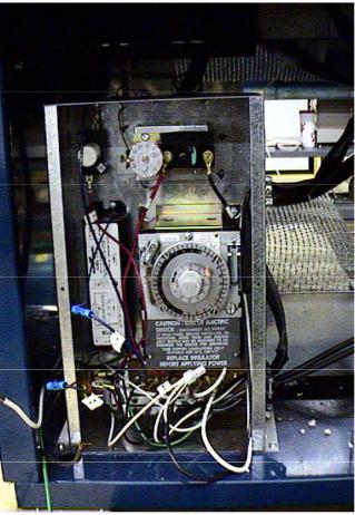
ELECTRICAL BOX –
The electrical box is located behind the louvered access panel. The box is capable of sliding out for service after the hold down screw is removed.
The box contains the power switch and defrost time clock.
POWER SWITCH –
The main power switch is located behind the front louvered access panel on the side of the electrical box. This power switch controls all power to the case. THE CABINET POWER SWITCH MUST BE IN THE OFF POSITION BEFORE STARTING ANY CLEANING OR SERVICE WORK ON THE EQUIPMENT.
DEFROST TIME CLOCK –
The time clock, located in the electrical box, provides a definite off-time so that the evaporator will clear itself of frost.
The clock is provided with pins to initiate defrost. The failsafe setting sets the length of defrost (from 2 minutes minimum to 110 maximum).
The clock is factory pre-set for 3 defrosts (at 6 a.m. , 2 p.m. and 10 p.m.) on the 4060 and 4072 at 20 minutes
6
each. There are 4 defrost on the 5272 (2 a.m., 8 a.m., 2 p.m., and 8 p.m.) at 30 minutes each
Additional defrost may be required for cases located in high humidity or high usage cases. If possible, avoid setting a defrost during the day, or peak usage periods. THE CLOCK TIME POINTER SHOULD BE SET TO THE CORRECT TIME OF DAY WHEN THE CABINET IS READY TO BE STARTED.
Setting the timer – Extra pins are provided with the timer.
♦Put pin in hole of dial face at the time you wish the cabinet to defrost. Note that there is an AM and PM section on the dial face. Be sure the pin is tight.
♦Set the length of time for the defrost (failsafe). Push down on the adjustment and slide it to the length of time. Do not set the time longer than 60 minutes.
♦Set the time pointer to the proper time of day and start cabinet.
CONNECTIONS -
a.Check cabinet thoroughly for loose nuts and bolts and electrical connections.
b.Inspect the refrigeration lines for any visible damage or chafing.
c.Replace electrical box cover.
d.Replace the louvered access panel.
e.Start the cabinet and allow to pull down to operating temperature before loading.
7
 Loading...