

Page 1
Manual
Installation
& Operation
REV. 0608
/CHINO
RHR-HEX, RHR-HEX2, RHR 1/2, RHR-SQ
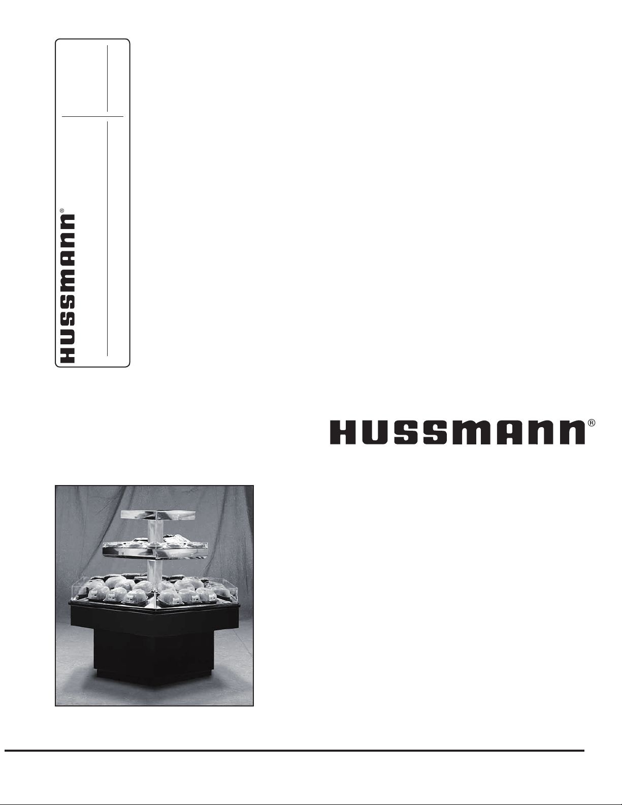
ISLAND HOT FOOD CASE
RHR-HEX, RHR2-HEX, RHR 1/2 HEX
ISLAND HOT FOOD CASE
P/N IGHT-RHR-HEX, RHR2HEX2, RHR 1/2 HEX, RHR SQUARE-0608
INSTALLATION & OPERATION GUIDE
Page 2

General Instructions
This equipment is to be installed
to comply with the applicable
NEC, Federal, State , and Local
Plumbing and Construction
Code h a ving j u risdict i o n .
IGHT-RHR, RHR2-HEX-0608
Table of Contents
General Instructions.....................................................2
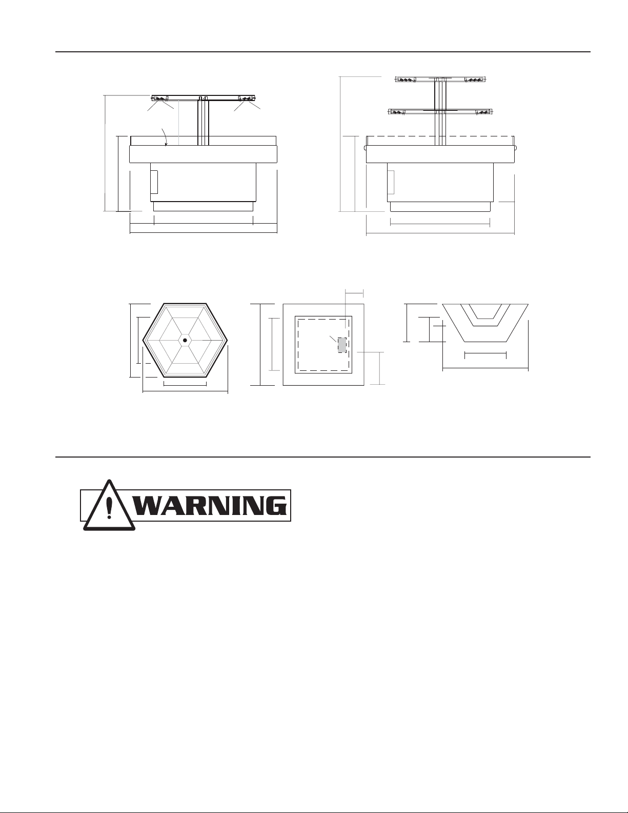
Cut and Plan Views ......................................................3
Installation .....................................................................3
Leveling .....................................................................................3
Bumper Installation Instructions................................................. 4
Electrical........................................................................8
Wiring Color Code ..................................................................... 8
Electrical Circuit Identication ....................................................8
Field Wiring and Serial Plate Amperage ....................................8
Ballast Location .........................................................................8
User Information ........................................................... 9
Food Handling ...........................................................................9
Important Operation Tips: .......................................................... 9
Controls .....................................................................................9
Overhead Heating System......................................................... 9
Care and Cleaning .....................................................................9
General Cleaning Rules............................................................. 9
Cleaning Instructions ............................................................... 10
Plexiglass and Acrylic Care ..................................................... 10
Antistatic Coatings ................................................................... 10
Cleaning Precautions............................................................... 10
Maintenance ................................................................ 11
Replacing Overhead Heat Lamps............................................ 11
Electrical Wiring Diagrams ........................................12
Wiring Diagrams .........................................................13
Appendices .................................................................21
Appendix A. - Temperature Guidelines .................................... 21
Appendix B. - Application Recommendations .......................... 21
Appendix C. - Field Recommendations ................................... 21
Appendix D. - Recommendations to User ............................... 21
This Booklet Contains Information on:
The RHR-HEX is a self-service Hot Food Hexagon-shaped
Island Stand, available in 4 and 6 foot sizes.
The RHR2-HEX is a similar unit, with the addition of a
second shelf: Both feature surface and overhead food
warmers, but both are also available with an overhead
Radiant Heat option.
Shipping Damage
All equipment should be thoroughly examined for shipping
damage before and during unloading.
This equipment has been carefully inspected at our factory
and the carrier has assumed responsibility for safe arrival.
If damaged, either apparent or concealed, claim must be
made to the carrier.
Apparent Loss or Damage
If there is an obvious loss or damage, it must be noted on
the freight bill or express receipt and signed by the carrier’s
agent; otherwise, carrier may refuse claim. The carrier will
supply necessary claim forms.
Concealed Loss or Damage
When loss or damage is not apparent until after all
equipment is uncrated, a claim for concealed damage
is made. Make request in writing to carrier for inspection
within 15 days, and retain all packaging. The carrier will
supply inspection report and required claim forms.
Shortages
Check your shipment for any possible shortages of
material. If a shortage should exist and is found to be the
responsibility of Hussmann Chino, notify Hussmann Chino.
If such a shortage involves the carrier, notify the carrier
immediately, and request an inspection. Hussmann Chino
will acknowledge shortages within ten days from receipt
of equipment.
Hussmann Chino Product Control
The serial number and shipping date of all equipment
has been recorded in Hussmann’s les for warranty and
replacement part purposes. All correspondence pertaining
to warranty or parts ordering must include the serial number
of each piece of equipment involved, in order to provide
the customer with the correct parts.
Keep this booklet with the case at all times for future reference.
/CHINO
A publication of HUSSMANN® Chino
13770 Ramona Avenue • Chino, California 91710
(909) 628-8942 FAX
(909) 590-4910
(800) 395-9229
2
Page 3
Rev. 0608
RHR2-HEX 6' & (4')
Self-Service Hot
Scale = 1/2"
431/4" (251/8")
Control
Panel
541/4" (473/8")
W
ar
m
in
g
G
ri
d
d
le
58"
21
1
/
16
"
32
9
/
16
"
101/2"
10
1
/2"
28
1
/2" (191/2")
Food
Warmer
12"
183/4"
13"
12
1
/4"
RHR SQUARE
Self Service Hot Food
20
11
/
16
"
47
3
/
8
"
27"
ELEC.
MECHANICAL
STUB UP AREA
4" X 6"
23
11
/
16
" (33
3
/
8
")
4'-67/16" (6'-53/
8
"
)
RHR-HALF-HEX-4' (6')
Self-Service Hot
14
1
/
8
" (24
5
/
8
")
2'-21/2" (3'-11/
2
"
)
RHR-HEX 6' & (4')
Self-Service Hot
431/4" (251/8")
Control Panel
641/4" (471/8")
Wa
rm
in
g
Gr
iddle
50
1
/
4
"
21
1
/
16
"
32
9
/
16
"
101/2"
Light
Food
Warmer
10
1
/2"
18"
281/2" (191/2")
Light
Food
Warmer
773/8"
371/2"
65
3
/
8
"
(47
3
/
8
")
48
3
/
4
"
(27
5
/
8
")
(261/2")
(547/16")
RHR-HEX 6' & (4')
PLAN VIEW
IMPORTANT: It is imperative that cases
be leveled front to back and side to
side prior to joining.A level case is
necessary to ensure proper operation.
Cut and Plan Views
Installation
Leveling
1. Check oor where cases are to be set to see if it’s
3
level. Determine where the highest part of the oor
Cases will be shimmed off this point Using case
blueprints, measure off and mark on oor the exact
dimensions of the case footprint Snap chalk line for
front and back position of base rail. Mark location
of each joint front and back. Use a transit to nd the
highest point along both lines. Mark the difference,
and place the appropriate number of shims required
to maintain high-point level.
Page 4
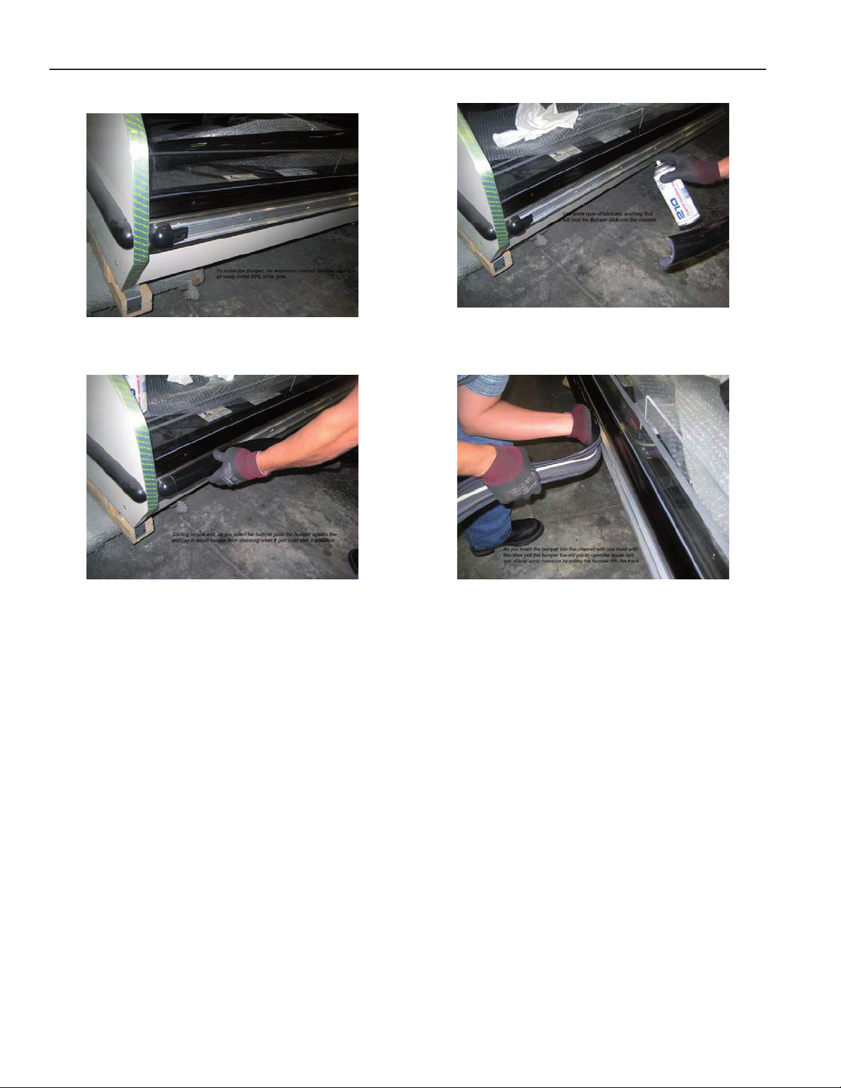
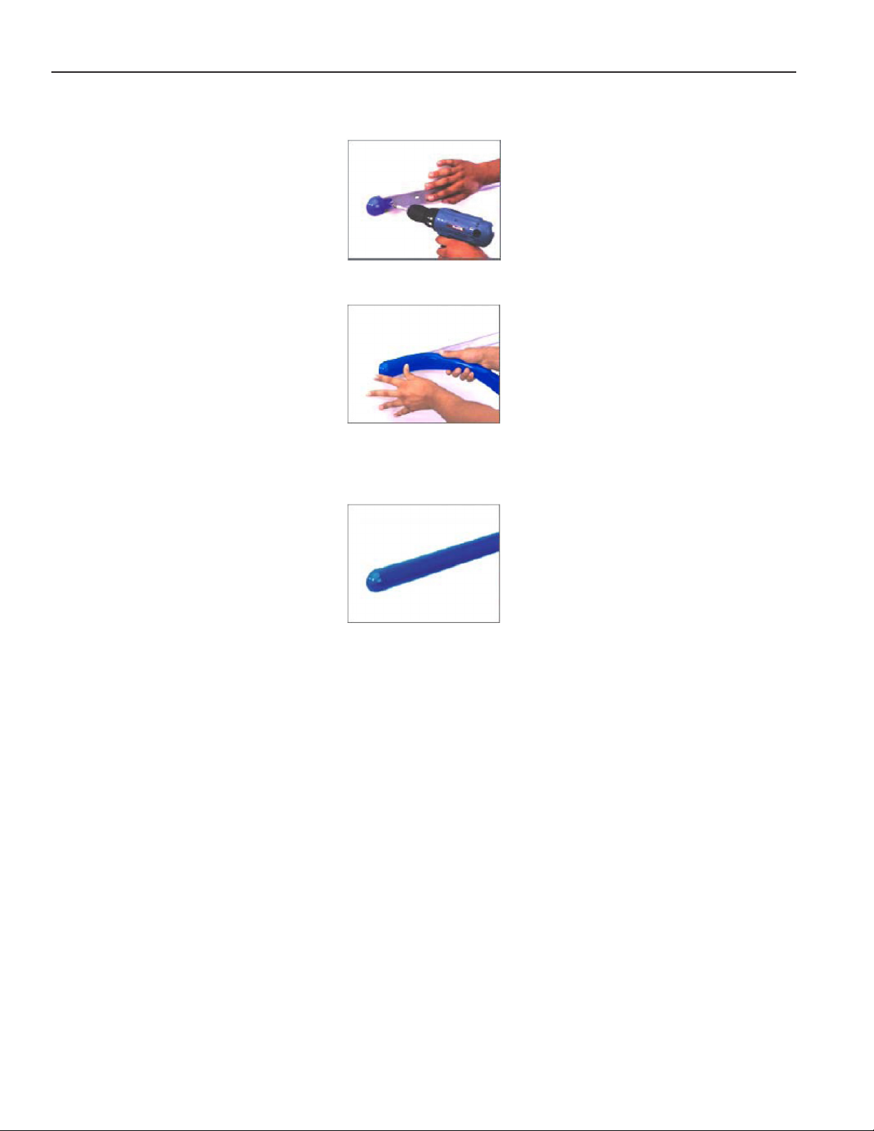
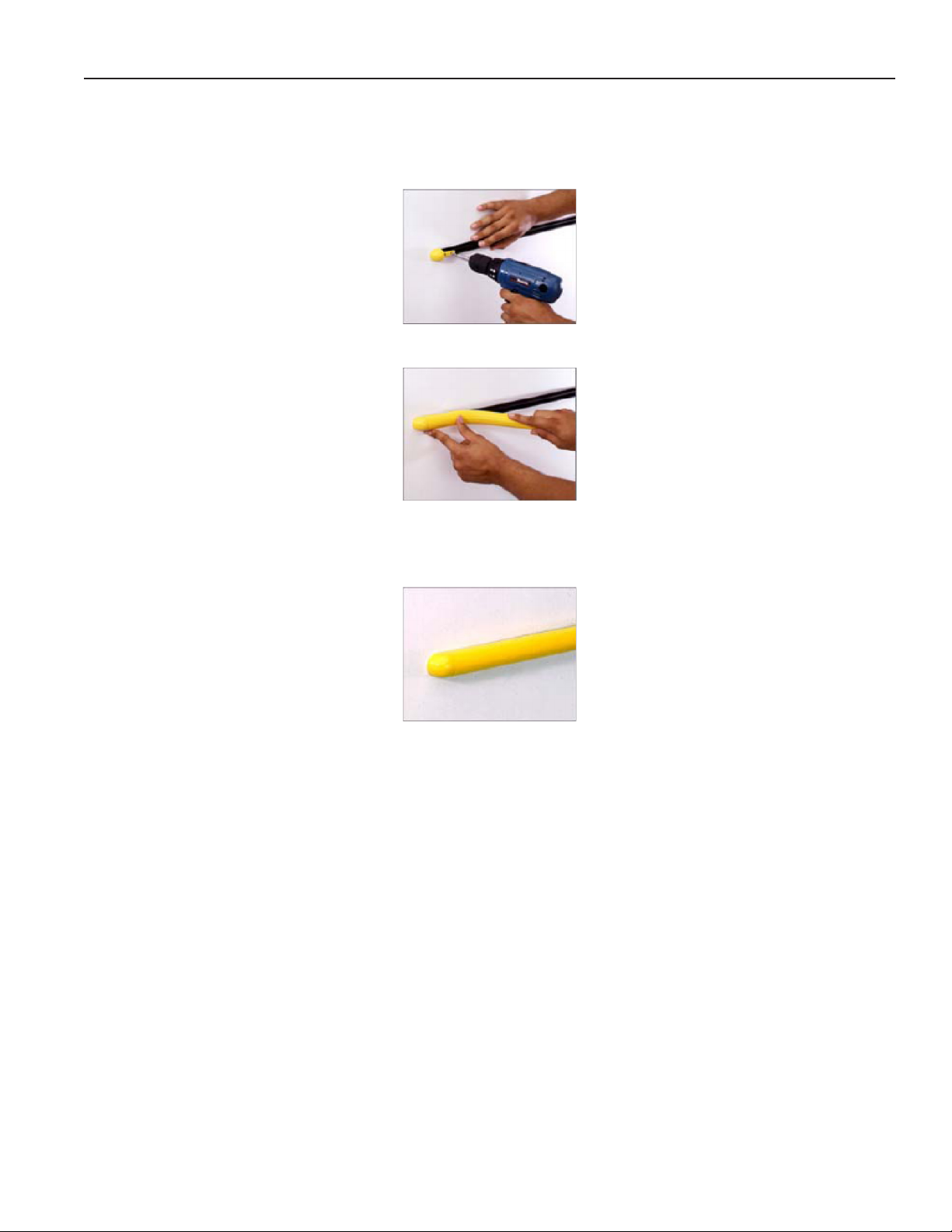
Bumper Installation Instructions
IGHT-RHR, RHR2-HEX-0608
Installation (Cont'd)
Step 1: Make sure the aluminum channel and end caps
are installed.
Step 3: Starting on one end: while inserting the bumper,
push it up against the end cap to prevent
the bumper from shrinking after installation
(when it gets cold).
Step 2: Use silicone lubricant to help the
bumper slide into the channel.
Step 4: As you insert the bumper into the channel with
one hand, pull the bumper toward you with
the other to open the inside lips. Slowly
apply pressure by rolling the bumper into
the track.
4
Page 5
Rev. 0608
Installation (Cont'd)
Boston Series 2000
NOTE: Flexible top: Over cut vinyl 1/8" for every 4' section for the exible top to ensure a proper t.
NOTE: Rigid Top: Do not over cut.
1. Attach the base and end/corner cap to the desired surface by inserting #8 pan head screws through the pre-slotted
holes in both the end cap and the base. Insert screws through the two holes of end cap and tighten.
2a. Flexible Top: Butt end of the vinyl top against end/corner cap. While applying pressure, bend back vinyl top so that
vinyl legs are positioned within the base grooves. Roll vinyl top over full length of base, then tap with rubber mallet
to ensure vinyl is securely locked into the base.
2b. Rigid Top: Snap the Rigid Top over the Rigid Base.
3. If necessary wipe clean with any household cleaning product.
Helpful Hints:
● For best results, before cutting, install a scrap piece of base into vinyl top to achieve a clean cut.
● Set the uncoiled flexible vinyl at room temperature 24 hours prior to installation.
● Lubricate the inside of the vinyl with soapy water or silicone before installing.
● Over cut the flexible vinyl and compression fit. Adding the additional materials will compensate for stretching which
occurs during installation.
5
Page 6
IGHT-RHR, RHR2-HEX-0608
Installation (Cont'd)
Boston 2000 Eco Series
1. Attach the base and end/corner cap to the desired surface by inserting #8 pan head screws through the pre-slotted
holes in both the end cap and the base. Insert screws through the two holes of end cap and tighten.
2a. Flexible Top: Butt end of the vinyl top against end/corner cap. While applying pressure, bend back vinyl top so that
vinyl legs are positioned within the base grooves. Roll vinyl top over full length of base, then tap with rubber mallet
to ensure vinyl is securely locked into the base.
2b. Rigid Top: Snap the Rigid Top over the Rigid Base.
3. If necessary wipe clean with any household cleaning product.
Helpful Hints:
● For best results, before cutting, install a scrap piece of base into vinyl top to achieve a clean cut.
● Set the uncoiled flexible vinyl at room temperature 24 hours prior to installation.
● Lubricate the inside of the vinyl with soapy water or silicone before installing.
● Over cut the flexible vinyl and compression fit. Adding the additional materials will compensate for stretching which
occurs during installation.
6
Page 7
Rev. 0608
Installation (Cont'd)
Boston 1000 Series
NOTE: Flexible top: Over cut vinyl 1/8" for every 4' section for the exible top to ensure a proper t.
NOTE: Rigid Top: Do not over cut.
Installation
1. Attach the base and end/corner cap to the desired surface by inserting #8 pan head screws through the pre-slotted
holes in both the end cap and the base. Insert screws through the two holes of end cap and tighten.
2a. Flexible Top: Butt end of the vinyl top against end/corner cap. While applying pressure, bend back vinyl top so that
vinyl legs are positioned within the base grooves. Roll vinyl top over full length of base, then tap with rubber mallet
to ensure vinyl is securely locked into the base.
2b. Rigid Top: Snap the Rigid Top over the Rigid Base.
3. If necessary wipe clean with any household cleaning product.
Helpful Hints:
● For best results, before cutting, install a scrap piece of base into vinyl top to achieve a clean cut.
● Set the uncoiled flexible vinyl at room temperature 24 hours prior to installation.
● Lubricate the inside of the vinyl with soapy water or silicone before installing.
● Over cut the flexible vinyl and compression fit. Adding the additional materials will compensate for stretching which
occurs during installation.
7
Page 8

Electrical
BEFORE SERVICING
ALWAYS DISCONNECT ELECTRICAL
POWER AT THE MAIN DISCONNECT
WHEN SERVICING OR REPLACING ANY
ELECTRICAL COMPONENT.
This includes (but not limited to) Fans, Heaters
Thermostats, and Lights.
RHR-HEX 6' & (4')
Self-Service Hot
Control Panel
Ballast
Ballast
(one for each light)
RHR2-HEX 6' & (4')
Self-Service Hot
Scale = 1/2"
Control
Panel
Ballast
Ballast
(one for each light)
Ballast for shelves
IGHT-RHR, RHR2-HEX-0608
Wiring Color Code
Electrical Circuit Identication
Standard lighting for all models will be uorescent lamps
located within the case at the top.
The switch controlling the lights and heaters are located
within an access panel on the side of the case.
Field Wiring and Serial Plate Amperage
Field Wiring must be sized for component amperes printed
on the serial plate.Actual ampere draw may be less than
specied. Case amperes are listed on the wiring diagram,
but due to parts availability they may vary slightly. Always
check the serial plate for the actual loads.
Ballast Location
8
Page 9

Rev. 0608
User Information
Food Handling
These hot tables are for short-term holding and display of
precooked hot foods. They are not intended to cool or reheat
food. The temperature of the food should be approximately
160°F when rst put into the hot table. Any attempt to use
the hot table to display large amounts of food for long
periods of time will result in dehydrated, overcooked and
unsafe food. The quality of food will progressively worsen
as the length of time increases. The deterioration of product
quality is a function of time and temperature. All products
are affected even though in a gravy or other liquid. They
may appear to withstand the temperature better than “dry”
foods such as fried chicken but this is not necessarily
true. ALL foods will continue to be affected by prolonged
exposure to elevated temperatures.
The following guidelines are provided only as a general
guide for the use of this equipment. The local health
agency for your area can provide specic temperature
requirements.
Critical attention must be given to the heat controls for
these hot tables. Both the upper and lower heat controls
must be adjusted to maintain proper food temperatures. Hot
foods should be held at a minimum temperature of at least
140°F (60°C) according to 1993 FDA Food Code. However,
increasing the temperature too high will also cause the
food to overcook, dry out, lose its avor, texture and color.
Food held for prolonged periods at high temperatures will
also lose some of their nutritional value.
All griddle type units are designed to maintain temperatures
above the FDA guideline of 140°F. This is product
temperature, not air or griddle temperature. Due to the open
design of these units, they must be loaded with product for
proper operation. When units are empty, they experience
rapid rise of heated air from air outside the case. This action
gives empty units a false, lower than desired, temperature
reading. Loading the case traps the air at the griddle,
raising temperatures to the 165°F to 185°F range, keeping
product well above the FDA guidelines. Remember, these
units must be loaded with product to maintain safe product
temperature.
Different foods will require different control settings. The
type of food, the quantities of food and length of time that
it is to remain in the hot table must be considered when
establishing control settings. Therefore, it must be the
user’s responsibility to establish the correct control settings
to maintain the food at the safest, tastiest and most saleable
condition.
FOOD TEMPERATURES CAN BE
ACCURATELY DETERMINED ONLY
THROUGH THE USE OF FOOD
THERMOMETERS!
Important Operation Tips:
• Preheat case 30 minutes before loading product
using higher settings.
• Using thermometer, check product before loading
in case (150°F-160°F).
• At start, set lamps to “3”.After loading, recheck
temperature every 1/2 hour to see that unit is
operating properly.Adjust the thermostat (a higher
number for hotter and a lower number for cooler)
to maintain product temperature of 140°F (60°C)
minimum. The setting will depend on the type of
product being displayed Be sure to test product
temperature with a thermometer frequently for good
product maintenance.
• Food should maintain contact directly with the
“griddle” at all times.
Controls
There are three sets of controls for the hex case, each
behind its own access panel located on the side of the
case. The dial with the numbered settings is for the griddle.
The other dials/switches are for the overhead lights and
heating components.
Overhead Heating System
Cal rod units are located above the griddles to provide
top heat. To obtain the proper food temperatures, they
must be adjusted. Settings may vary depending on
food composition. Maximum limits should be avoided
to prevent overcooking or drying out food.
Care and Cleaning
Long life and satisfactory performance of any equipment
is dependent upon the care it receives. With this in mind,
all of the exposed work surfaces of these hot tables have
been made entirely of easy to clean stainless steel.
Stainless steel is one of the easiest materials to clean and
keep clean. Normally it is just a matter of wiping spills off the
surface when they happen followed by a thorough cleaning
with soap and water at the end of the day. Frequent and
regular cleaning will prevent the buildup of baked on difcult
to remove spills. Many types of cleansers are available and
safe to use on stainless steel. However, ordinary steel wool
and steel brushes should not be used. Small particles of
the steel may become imbedded into the stainless steel
surfaces that will eventually rust and stain.
General Cleaning Rules
1. ALLOW SURFACES TO COOL BEFORE
HANDLING.
2. Clean frequently and regularly.
3. Rinse thoroughly after cleaning.
4. Remove surface spills immediately with a damp
cloth.
9
Page 10

User Information (Cont'd)
IGHT-RHR, RHR2-HEX-0608
Cleaning Instructions
1 . Turn temperature control knobs to OFF position.
2. Allow unit to cool completely.
3. Wipe entire unit with clean cloth and mild detergent.
The EXTERIOR surfaces of these hot tables must be
cleaned with a mild detergent and warm water to protect
and maintain their attractive nish. Never use abrasive
cleaners or scouring pads.
TO REMOVE “BAKED-ON” SPLATTER, GREASE OR
LIGHT DISCOLORATION TO STAINLESS STEEL.
CLEANSING AGENT APPLICATION
Grade F Italian Pumice........Scour or rub with damp cloth
Liquid NuSteel.....................Scour with small amount on
dry cloth
Paste NuSteel
Household Cleansers...........Rub with damp cloth
TO REMOVE HEAT TINT OR HEAVY
DISCOLORATION
CLEANSING AGENT APPLICATION
Allen Stainless Steel Polish........Small amount on damp
cloth
Birdsall “Staybright” ...................Rub with damp cloth
Wyandotte
Bab-O
Nusteel.......................................Rub with stainless steel
wool
Plexiglass and Acrylic Care
Cleaning
Clean with plenty of nonabrasive soap (or detergent) and
lukewarm water, using the bare hand to feel and dislodge
any caked-on dirt. A soft, grit-free cloth, sponge, or chamois
may be used, but only as a means of carrying the water to
the plastic. Dry with a clean damp chamois or clean soft
cloth such as cotton annel. Hard, rough cloths or paper
towels will scratch the acrylic and should not be used.
Waxing
If after removing dirt and grease, the acrylic can be waxed
with a good grade commercial wax. This will improve
the appearance of the surface by lling in most minor
scratches. Wax should be applied in a thin even coat, and
brought to a high polish by rubbing lightly with a dry clean
soft cloth, such as a cotton annel. Excessive rubbing may
cause scratching and/or buildup an electrostatic charge,
which attracts dust and dirt to the surface. Blotting with a
clean damp cloth is recommended to remove charge.
Antistatic Coatings
For acrylic used indoors, antistatic coatings successfully
prevent the accumulation of electrostatic charge for periods
of several months, if the surface is not washed or wiped
down with a wet cloth. Between applications of the antistatic
coatings, the parts need only be dusted with a soft clean
cloth to maintain a good appearance. In use, liquid antistatic
coatings should be applied in a very thin even coat. If beads
appear as it is applied, the coat is too thick and the excess
should be removed with another cloth. Allow the coating to
dry, then bring to a high gloss with a soft cloth.
Cleaning Precautions
To preserve the attractive nish, use warm water and a mild
detergent to wash the exterior of the cases. DO NOT USE
ABRASIVE CLEANERS OR STEEL WOOL SCOURING
PADS as these will mar the surface.
10
Page 11

Rev. 0608
ALWAYS DISCONNECT ELECTRICAL POWER
AT THE MAIN DISCONNECT WHEN SERVICING
OR REPLACING ANY ELECTRICAL COMPONENT.
This includes (but not limited to) Fans, Heaters,
Thermostats, and Lights.
The Heat lamps used in these cases get
EXTREMELY HOT! NEVER touch a lamp
until the case has had ample time to cool
down! It is also highly recommended to handle
lamps with gloves or use a cloth rag - not just
for the heat factor, but also the oils in your
fingers will drastically shorten the life of the lamp.
Maintenance
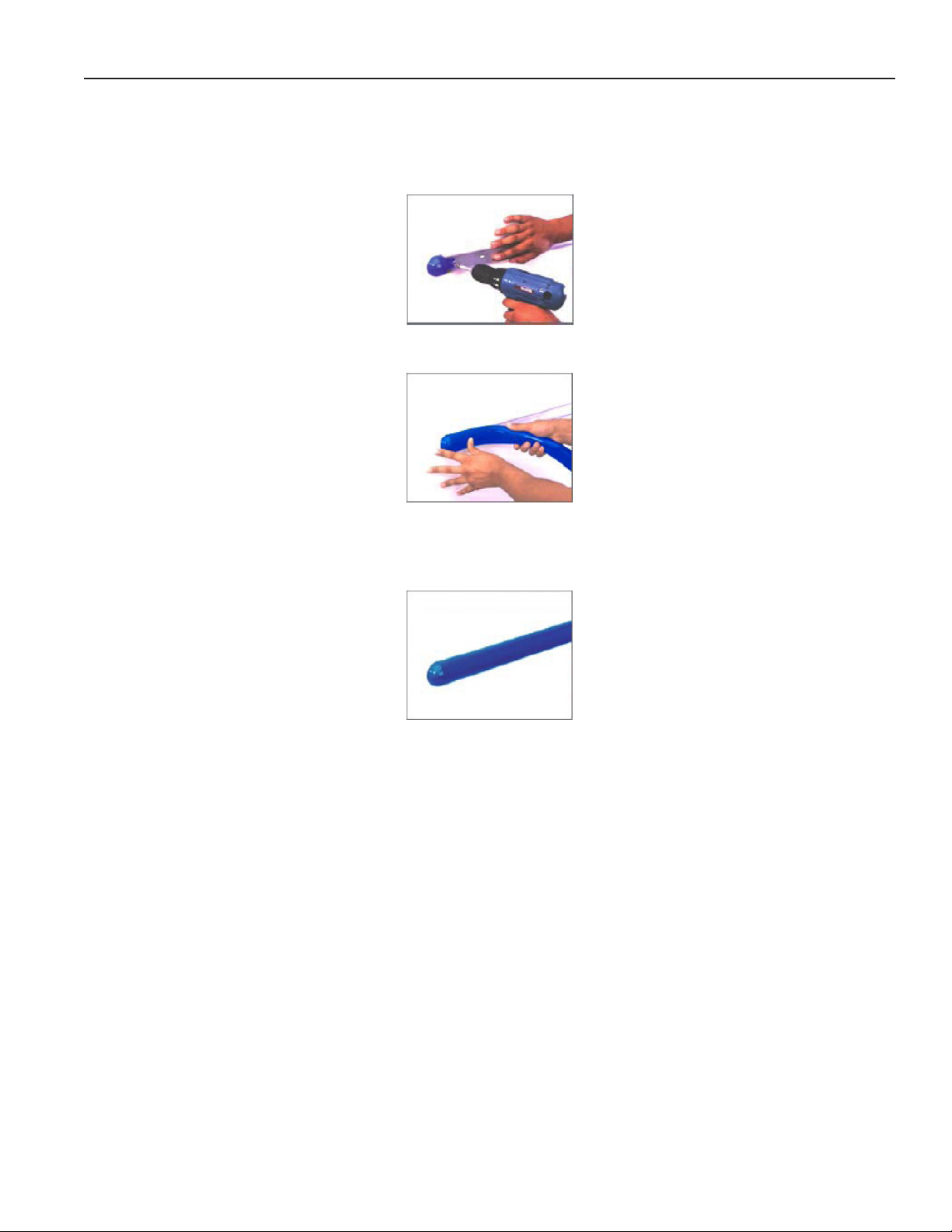
Replacing Overhead Heat Lamps
Overhead Halogen and Merco lamps are designed to
last through many hours of use. Should there be a need
to replace one, it is as simple as replacing a standard
uorescent light bulb.
1. Turn light switch to OFF before replacing any
lighting components.
2. Disconnect light xture by removing power cord
from socket in the right rear interior corner of the
merchandiser.
3. Place the shelf on a at surface to remove the clear
plastic protective shield from the xture. Carefully
insert one nger between the xture socket and
the protective shield. Use other hand to “pinch”
lens cover (and simultaneously hold the xture in
place) while lifting with inserted nger.When shield
separates from xture at one end, remove it by
SLOWLY pulling remainder of shield away from
xture.
4. Remove lamp by depressing spring loaded socket
at end of xture, and swinging opposite end of lamp
from it’s former position.
5. Using gloves or covering for lamp, insert new lamp
into spring loaded socket, depressing socket until
opposite end of lamp properly enters stationary light
socket.
6. Return lamp to original position by lightly pinching it
in from each side, and inserting shield anges into
xture channel. Continue process along length of
lamp shield until it is in it’s nal proper position.
7. Return lamp to original position by lightly pinching it
in from each side, and inserting shield anges into
xture channel. Continue process along length of
lamp shield until it is in it’s nal proper position.
11
Page 12

IGHT-RHR, RHR2-HEX-0608
Electrical Wiring Diagrams
RHR-HEX RHR-HEX 4’ W6100012
5’ 6” W6100002
RHR-HEX-2 (w/shelf) OLD► 4’ W6100003
NEW ► 4’ W6100020
6’ W6100015
RHR-Square 4’ W6100005
RHR-1/2-HEX 4’ W6100007
6’ W6100008
12
Page 13

Rev. 0608
Sheet 1 of 1
final
D.QUAN
Date:
Project Title:
Drawing No.:
Drawn By:
Next Assembly:
Drawing Title:
Date:
Hussmann Corporation
13770 Ramona Avenue
Chino, CA. 91710
(909)-590-4910
Lic.#: 644406
Revisions:
No. Description:
Checked By:
By:
7
3
P1
5
1 2 4
6
P
H2
L2
L1
H1
L
White
White
Red
White
White
Red
White
White
Red
White
White
Red
White
White
Red
White
White
Red
L
Griddle
(6) 206W/220VAC Flexible Heater Pad #225-01-6770/-6770T
Overhead Heating Element
HE-04-68" #125-01-3235
2700 W / 240 VAC
Bulb Sensor
Pilot Light
Pilot Light
Electronic
T-Stat
s
L1
L2
N
G
POWER
#125-01-0311
L3
Contactor
#125-001-1001
(2) F14T5/TL830
WH2-120-135
(2) F14T5/TL830
WH2-120-135
(2) F14T5/TL830
WH2-120-135
Ledge Lights-optional
Overhead Lighting
INCANDESCENT LAMPS
GE APPLIANCE BULB PC15206-100A15-CD1-100 WATT - 115V
(6) 125-03-1206 100WATT INCANDESCENT LAMP
(6) 125-01-0287 LIGHT SOCKET
L
SWITCH
125-01-0311
15 AMP
FUSE 125-01-3282
FUSE HOLDER
125-01-3283
L
L
SWITCH
125-01-0311
~208 / 240V - 1 Ø - 60Hz
M
COOLING
FAN
MOTOR
SAFETY T-STAT
CLOSE ON RISE
NGT # 11S31T4444
225-01-0076
ON: 98.6°F
OFF: 80.6°F
(LOCATED IN COLUMN)
Note: Case MUST be grounded
RHR-Hex-4' basic
RHR Hex 4' Case Wiring
W6100012
06.12.2000
Loads, amp
208 V 240 V
L1
L2
L3
19.7
14.2
0.0
22.8
16.4
0.0
1 DELETED (1) 225-01-3301 08/05/05 D.Q.
®
Wiring Diagrams
13
Page 14

IGHT-RHR, RHR2-HEX-0608
DATE:
PROJECT TITLE:
DRAWING #:
DRAWN BY:
PRODUCTION ORDER #:
DRAWING TITLE:
DATE:
Hussmann Corporation, Int'l.
13770 Ramona Avenue
Chino, CA. 91710
(909)-590-4910 Lic.#: 644406
REVISIONS:
#: DESCRIPTION:
CHECKED BY:
BY:
FILE LOCATION:
Boris Kasrel
PAGE OF
®
1
1
2/1/00
B Updated dwg; added 2 limiters and 1 t-stat 2/15/08 JR
RHR-Hex-5'6"
W6100002
RHR Hex 5'6"
GRIDDLE
HEATING PADS - 451W 1.88A @ 240 VAC - EA.
(6) 225-01-6771
OVERHEAD CANOPY INSTALLATION
TUBULAR HEATER
125-01-3247A
2250W 9.4A @ 240 VAC
PACKTRONICS
CONTROLLER
225-01-3229
L
TEMP. CONTROL
SENSOR
225-01-3228
6
421 5
P1
3 7
L
P
H2
L2
L1
H1
L
L1
L2L3N
G
L
MAIN POWER
~208 / ~240 VAC 50/60 HZ
125-01-0002
SQUARE -D
CONTACTOR
8910DPA43V02
INFINITE
CONTROL
125-01-1663
LIGHT SWITCH
125-01-0311
COOLING
FAN MOTOR
.18A @ 120VAC
125-01-2012-A
SAFETY T-STAT
CLOSE ON RISE
NGT # 11S31T4444
225-01-0076
ON: 98.6°F
OFF: 80.6°F
(LOCATED IN COLUMN)
INCANDESCENT LAMP
BULB 60W 115V
(6) 125-03-1206
RED # 12
GREEN # 12
BLACK # 12
BLUE # 12
WHITE # 14
M
SWITCH
125-01-0311
PILOT LIGHT
175-01-1102C
LIMIT SWITCH
TEMPCO TST-112-119
225-01-1702
THERMOSTAT
TEMPCO
TEB33000
225-01-1700
LIMIT SWITCH
TEMPCO TST-112-119
225-01-1702
15A
20A
15A
15A
(2) 15 AMP FUSE
125-01-8604
FUSE HOLDER
125-01-8610
15 AMP FUSE
125-01-8604
FUSE HOLDER
125-01-8605
20 AMP FUSE
125-01-8537
FUSE HOLDER
125-01-8612
LOADING
208 V 240 V
L1
L2
L3
21.1
9.8
8.2
23.9
11.3
9.4
6180W @ 240VAC
4695W @ 208VAC
Wiring Diagrams (Cont'd)
14
Page 15

Rev. 0608
Sheet 1 of 1
final
BK
Boris Kasrel
Date:
Project Title:
Drawing No.:
Drawn By:
Next Assembly:
Drawing Title:
Date:
Hussmann Corporation
13770 Ramona Avenue
Chino, CA. 91710
(909)-590-4910
Lic.#: 644406
Revisions:
No. Description:
Checked By:
By:
73
P1
51 2 4 6
P
H2
L2
L1
H1
L L
Griddle
(2) sets of 3 pads - 206 W / 220 VAC
Bulb
Sensor
Temp. Control
Pilot Light
Pilot Light
Electronic T-Stat
Shelf Installation
(6) F13DBX23T4/SPX35
Fluorescent Double Biax Lamps
(6) Ballast 4111F2RP
Control Box Installation
W
hite
W
hite
Red
White
White
Red
W
hite
White
Red
White
W
hite
Red
White
W
hite
Red
W
hite
White
Red
Cal-Rod 980W /~240V
Cal-Rod 1200W / ~240V
Infinite
Control
P
H2
L2
L1
H1
L
Pilot Light
Overhead (crown) Installation
(3) F13DBX23T4/SPX35
Fluorescent Double Biax Lamps
Ballast 4111F2RP
Infinite
Control
M
Overhead
Ballast Cooling
POW
ER
#12
5-0
1-031
1
s
L1L2L3
N
G
LIGH
TS
#12
5-0
1-031
1
#225-01-3301A
NGT 11S11T444
Safety T-Stat
ON: 183°F
OFF:210°F
#225-01-0076
NGT 11S31T444
Column Heat Limit
ON: 98.6°F
OFF: 80.6°F
Note: Case MUST be grounded
RHR - Hex 4' w/shelf Case Wiring
RHR - Hex 4' Shelf Unit
LOADING
208 V 240 V
L1L2L3
16.0
13.1
18.1
14.6
10/22/99
W6100003
®
Wiring Diagrams (Cont'd)
15
Page 16

IGHT-RHR, RHR2-HEX-0608
DATE:
PROJECT TITLE:
DRAWING #:
DRAWN BY:
PRODUCTION ORDER #:
DRAWING TITLE:
DATE:
Hussmann Corporation, Int'l.
13770 Ramona Avenue
Chino, CA. 91710
(909)-590-4910 Lic.#: 644406
REVISIONS:
#: DESCRIPTION:
CHECKED BY:
BY:
FILE LOCATION:
D.QUAN
PAGE OF
®
1
1
B Updated dwg; add limit switches and t-stats 2/15/08 JR
C Remove inf switch ctrls;add packtronics ctrls 2/21/08 JR
08/05/05
RHR-HEX-2 HEX CASES
W6100020
RHR-HEX-2-4' CASE W/ SHELF UNIT
GRIDDLE
HEATING PADS - 206W .86A @ 240 VAC - EA.
(6) 225-01-6770
SHELF INSTALLATION
TUBULAR HEATER
125-01-0478A
1200W 5A @ 240VAC
OVERHEAD CANOPY INSTALLATION
TUBULAR HEATER
125-01-1006A
1800W 7.5A 240 VAC
L
PACKTRONICS
CONTROLLER
225-01-3229
L
TEMP. CONTROL
SENSOR
225-01-3228
64
2
1 5
P1
3 7
L
L1
L2L3N
G
L
MAIN POWER
~208 / ~240 VAC 50/60 HZ
125-01-0002
SQUARE -D
CONTACTOR
8910DPA43V02
LIGHT SWITCH
125-01-0311
LIGHT SWITCH
125-01-0311
COOLING
FAN MOTOR
.18A @ 120VAC
125-01-2012-A
SAFETY T-STAT
CLOSE ON RISE
NGT # 11S31T4444
225-01-0076
ON: 98.6°F
OFF: 80.6°F
(LOCATED IN COLUMN)
RED # 12
GREEN # 12
BLACK # 12
WHITE # 14
M
INCANDESCENT LAMP
BULB 60W 115V
(3) 125-03-1206
PILOT LIGHT
175-01-1102C
INCANDESCENT LAMP
BULB 60W 115V
(6) 125-03-1206
LIMIT SWITCH
TEMPCO TST-112-119
225-01-1702
15A
(2) 15 AMP FUSE
125-01-8604
FUSE HOLDER
125-01-8610
15A
15A
(2) 15 AMP FUSE
125-01-8604
FUSE HOLDER
125-01-8610
15A
PACKTRONICS
CONTROLLER
225-01-3229
PILOT LIGHT
175-01-1102C
L
TEMP. CONTROL
6
4
21 5
P1
3 7
SENSOR
225-01-3228
LIMIT SWITCH
TEMPCO TST-112-119
225-01-1702
PACKTRONICS
CONTROLLER
225-01-3229
PILOT LIGHT
175-01-1102C
L
TEMP. CONTROL
6
4
2
1 5
P1
3 7
SENSOR
225-01-3228
LIMIT SWITCH
TEMPCO TST-112-119
225-01-1702
NOTE: CASE MUST
BE GROUNDED
LOADING
208 V 240 V
L1
L2
19.8
15.3
22.2
17.7
5328W @ 240VAC
4118W @ 208VAC
Wiring Diagrams (Cont'd)
16
Page 17

Rev. 0608
DATE:
PROJECT TITLE:
DRAWING #:
DRAWN BY:
PRODUCTION ORDER #:
DRAWING TITLE:
DATE:
Hussmann Corporation, Int'l.
13770 Ramona Avenue
Chino, CA. 91710
(909)-590-4910 Lic.#: 644406
REVISIONS:
#: DESCRIPTION:
CHECKED BY:
BY:
FILE LOCATION:
D.QUAN
---
PAGE OF1 1
06/08/01
1 UPDATED CASE TOTAL LOADING 06/27/01 AEC
2 DELETED (1) 225-01-3301 08/05/05 D.Q.
GRIDDLE
(2) SETS OF 3 FLEXIBLE HEATING PA DS - 451W / ~240 VAC - EA.
SHELF INSTALLATION
TUBULAR HEATER
125-01-3247A
2250W / ~240VAC
(OUTER UNIT)
TUBULAR HEATER
125-01-1006A
980W / ~240 VAC
(INNER UNIT)
OVERHEAD CANOPY INSTALLATION
TUBULAR HEATER
125-01-3246A
1850W / ~240 VAC
L
P
H2
L2
L1
H1
L
M
PACKTRONICS
CONTROLLER
225-01-3229
PILOT
LIGHT
L
TEMP. CONTROL
SENSOR
225-01-3228
6
42
1 5
P1
3 7
CAP EACH RED LEAD
ON EACH HEATER
L
P
H2
L2
L1
H1
L
L1
L2
L3
N
G
L
MAIN POWER
~208 / ~240 VAC - 3Ø - 50/60 HZ - 5W
125-01-0002
SQUARE -D
CONTACTOR
8910DPA43V02
INFINITE CONTROL
125-01-1663
INFINITE CONTROL
125-01-1663
PILOT
LIGHT
PILOT
LIGHT
LIGHT SWITCH
125-01-0311
LIGHT SWITCH
125-01-0311
COOLING
FAN MOTOR
SAFETY T-STAT
CLOSE ON RISE
NGT # 11S31T4444
225-01-0076
ON: 98.6°F
OFF: 80.6°F
(LOCATED IN COLUMN)
INCANDESCENT LAMPS
GE APPLIANCE BULB PC15206-100A15-CD1-100 WATT- 115V
(6) 125-03-1206 100WATT INCANDESCENT LAMP
(6) 125-01-0287 LIGHT SOCKET
INCANDESCENT LAMPS
GE APPLIANCE BULB PC15206-100A15-CD1-100 W
TT- 1
(6) 125-03-1206 100WATT INCANDESCENT LAMP
(6) 125-01-0287 LIGHT SOCKET
RHR HEX CASES
W6100015
RHR HEX 5'-6" - (1) SHELF UNIT
H:\WIRESCHEMATICS\NEWWIRING
NOTE:
CASE MUST BE
GROUNDED
28.3
21.4
18.6
24.5
18.6
16.1
L1
L2
L3
208 V 240 V
LOADING
®
Wiring Diagrams (Cont'd)
17
Page 18

IGHT-RHR, RHR2-HEX-0608
DATE:
:# GWD:ELTIT TCEJORPDRAWN BY:
PRODUCTION ORDER #:
DRAWING TITLE:
DATE:
REVISIONS:
:YB
DEKCE
HC:
N
OI
TPI
RCSED :#
BY:
FILE LOCATION:
ADRIAN E. CRISCI
AEC
PAGE OF
HUSSMANN CORPORATION
13770 RAMONA AVENUE
CHINO, CA.91710
(909) 590-4910 LIC.#: 644406
1
2
3
1 1
10/22/99
H:\WIRESCHEMATICS\NEW-WIRING
RHR CASES
W6100005
4' x 4' SQUARE CASE MODEL
REPLACE CONTACTOR FOR RELAY 02/22/02 AEC
BROUGHT TO SPEC FROM ORIGINAL BY AEC 10/22/99 02/22/02 AEC
RELAY OMRON
G7L-2A-TUBJ-CB
125-01-3182
LIGHT SWITCH
TIPPETTE
125-01-0311
L
SWITCH
125-01-0311
MAIN
POWER
L
L1
L2L3N
G
~208 / 240 VAC - 1Ø - 50/60 Hz. - 4W
BALLAST MAGNETEK
4111F2RP
(8) 125-01-3240
INFINITE
CONTROL
125-01-1663
PILOT
LIGHT
BALLAST
SAFETY T-STAT
NGT CONTROLS™
11S11T444
ON: 183°F / OFF: 210°F
225-01-3301A
OVERHEAD LIGHTS
FLUORESCENT DOUBLE
BIAX LAMPS
(8) F13DBX23T4/SPX35
OVERHEAD HEATER
WATLOW™ HE-08
(1) 3550W @ ~ 240 VAC
125-01-3243
GRIDDLE HEATERS - THERMOFLEX™
(4) 364W @ ~240 VAC
225-01-6790T
PACKTRONICS
CONTROLLER
225-01-3229
PILOT
LIGHT
L
TEMP. CONTROL
SENSOR
225-01-3228
6421 5
P1
3 7
L
P
H2
L2
L1
H1
M
OVERHEAD COOLING
AXIAL FAN -
COMAIR™
MX2B1-E1
125-01-2012
NOTE: CASE MUST
BE GROUNDED
26.5
23.9
~
20.6
18.1
~
L1L2L3
208 V 240 V
LOADING
Wiring Diagrams (Cont'd)
18
Page 19

Rev. 0608
Sheet 1 of 1
X
Boris Kasrel
Date:
Project Title:
Drawing No.:
Drawn By:
Next Assembly:
Drawing Title:
Date:
Hussmann Corporation
13770 Ramona Avenue
Chino, CA. 91710
(909)-590-4910
Lic.#: 644406
Revisions:
No. Description:
Checked By:
By:
BK
73
P1
51 2 4 6
P
H2
L2
L1
H1
L
W
hite
W
hite
Red
W
hite
White
Red
White
W
hite
Red
BBB
Pilot
Light
Temp Control
Bulb
(3) Heater Pad 206 W / 220
VAC 225-01-6770 / ...-6770T
Griddle
HE-07 #125-01-3242
Overhead Installation
(3) Compact Double Biax Lamps
F13DBX23T4/SPX35
Infinite
Control
Pilot
Light
L
Electronic
T-Stat
Ballast
4111F2RP
208 / 240 VAC - 1 Ø - 50 / 60 Hz
Overhead
Ballast Cooling
M
L1
L2
N
G
L3
Power
125-01-0311
Light
s
125-01
-0311
Cal-Rod Htr 1250 W / 240 VAC
DPSTRelay, 25A
125-01-3182
#225-01-3301A
NGT 11S11T444
Safety Limit
ON: 183°F
OFF: 210°F
RHR HEX - 4'/ Half Case
Flr Lamps, Contactor
Note: Case MUST be grounded
LOADING
208 V 240 V
L1L2L3
9.0
7.2
10.2
8.3
10/22/99
W6100007
®
Wiring Diagrams (Cont'd)
19
Page 20

Sheet 1 of 1
final
Boris Kasre
Date:
Project Title:
Drawing No.:
Drawn By:
Next Assembly:
Drawing Title:
Date:
Hussmann Corporation
13770 Ramona Avenue
Chino, CA. 91710
(909)-590-4910
Lic.#: 644406
Revisions:
No. Description:
Checked By:
By:
BK
73
P1
51 2 4 6
P
H2
L2
L1
H1
L L
Griddle Heaters Pads
(2) sets of 3 pads - 451 W / 220 VAC
Overhead Heating
Element
Bulb
Sensor
Temp. Control
Pilot Light
Pilot Light
Electronic T-Stat
Light
s
1
25-01-0311
Overhead Lights
(6) F13DBX23T4/SPX35
Fluorescent Double Biax Lamps
(6) Ballast 4111F2RP
Overhead
Ballast Cooling
(2) 2500 W / 240 VAC
M
s
L1L2L3
N
G
Power Switc
h
1
25-01-0311
W
hite
W
hite
Red
White
W
hite
Red
W
hite
White
Red
#225-01-3301A
NGT 11S11T444
Safety Limit
ON:183°F
OFF: 210°F
208 / 240 VAC - 1Ø - 50 / 60z.
RHR Hex 5'6" 1/2 Case Wiring
RHR-Hex-5'6" 1/2 Case
LOADING
208 V 240 V
L1L2L3
14.8
16.5
17.1
18.8
10/22/99
W6100008
Note: Case must be grounded
®
Wiring Diagrams (Cont'd)
IGHT-RHR, RHR2-HEX-0608
20
Page 21

Rev. 0608
Appendices
Appendix A. - Temperature Guidelines
1.0 Hot cases are tested to maintain all hot food at
140°F - 150°F. These cases are not designed to
heat up or cook food. It is the user’s responsibility
to stock the hot food cases immediately after the
cooking of the food with a pulp temperature of at
least 150°F to 160°F.
All griddle type units are designed to maintain
temperatures above the FDA guideline of
140°F. This is product temperature, not air or
griddle temperature. Due to the open design
of these units, they must be loaded with
product for proper operation. When units are
empty, they experience rapid rise of heated
air from air outside the case. This action
gives empty units a false, lower than desired,
temperature reading. Loading the case traps
the air at the griddle, raising temperatures to
the 165°F to 185°F range, keeping product well
above the FDA guidelines. Remember, these
units must be loaded with product to maintain
safe product temperature.
Appendix B. - Application Recommendations
1.0 The installer should perform a complete start-up
evaluation prior to the loading of food into the hot
food case, which includes such items as:
a) Initial temperature performance, Griddles and
Hot Wells.
b) Observation of outside inuences such
as drafts, radiant heating from the ceiling
and from lamps. Such inuence should be
properly corrected or compensated for.
c) Complete start-up procedures should include
1. Heat/display lamps are lighting.
2. Indicator lamps on control panel(s) are
working
3. Auto-ll is functioning properly (Service
cases)
4. Hot Griddles are functioning.
Appendix C. - Field Recommendations
1.0 The most consistent indicator of display hot case
performance is temperature of the product itself.
NOTE: Public Health will use the temperature of the product
in determining if the hot case will be allowed to display
potentially hazardous food. For the purpose of this
evaluation, product temperature above the FDA Food
Code 1993 temperature for potentially hazardous food
will be the rst indication that an evaluation should be
performed. It is expected that all hot case will keep food
at the FDA Food Code 1993 temperature for potentially
hazardous food.
1.1 The following recommendations are made
for the purpose of arriving at easily taken and
understood data which, coupled with other
observations, may be used to determine whether
a hot case is working as intended:
a) INSTRUMENT - A stainless steel stem-type
thermometer is recommended and it should
have a dial a minimum of 1 inch internal
diameter. A test thermometer scaled only
in Celsius or dually scaled in Celsius and
Fahrenheit shall be accurate to 1°C (1.8°F).
Temperature measuring devices that are
scaled only in Fahrenheit shall be accurate to
2°F. The thermometer should be checked for
proper calibration. (It should read 32°F when
the stem is immersed in an ice water bath).
b) LOCATION - The thermometer must be
inserted into the food itself to acquire proper
food pulp temperature.
c) READING - The thermometer reading should
be made only after it has been allowed to
stabilize, i.e., maintain a constant reading.
Loading Product: Cases should be allowed
to heat up for one hour before product is
loaded.
Temperature adjustments: Allow 4 hours after
adjustment has been made before testing
pulp temperature of product.
d) OTHER OBSERVATIONS - Other
observations should be made which may
indicate operating problems, such as
unsatisfactory product, feel/appearance.
Appendix D. - Recommendations to User
1.0 The manufacturer should provide instructions and
recommendations for proper periodic cleaning.
The user will be responsible for such cleaning,
including the cleaning of equipment within the
compartment and the hot area(s). Cleaning
practices, particularly with respect to proper
refrigerator unloading and warm-up, must be in
accordance with applicable recommendations.
1. Allow the case to preheat for one hour prior
to loading.
2. Hot foods should enter the case directly after
cooking or no lower than 150° - 160°F. The
Hot Cases are not designed to heat up or
cook food.
3. Self Service - be sure to display product in
single layer in direct contact with heating
surface.
21
Page 22

Appendices (Cont'd)
IGHT-RHR, RHR2-HEX-0608
4. All griddle type units are designed to maintain
temperatures above the FDA guideline of
140°F. This is product temperature, not air or
griddle temperature. Due to the open design
of these units, they must be loaded with
product for proper operation. When units are
empty, they experience rapid rise of heated
air from air outside the case. This action
gives empty units a false, lower than desired,
temperature reading. Loading the case traps
the air at the griddle, raising temperatures to
the 165°F to 185°F range, keeping product
well above the FDA guidelines. Remember,
these units must be loaded with product to
maintain safe product temperature.
5. Check the food pulp temperature frequently
with a thermometer to make sure it is at
the proper holding temperature. Hot foods
should be at 140°F. The thermometer must
be inserted into the food itself for the proper
temperature.
6. Do not display more food than will be sold
within a 4 hour period.
7. When restocking, bring older food to the
front, and stock fresher food on top.
8. Clean spills as soon as they happen.
9. Fingerprints and food splatter will drastically
shorten bulb life. Clean splatter off the bulbs
immediately with a soft cloth. When handling
bulbs, wear cotton gloves or use a cotton
rag/towel.
10. When “freshening” foods such as macaroni
and cheese with added water, heat the water
in a clean container until it is 10°F to 20°F
above the desired holding temperature of the
food. This will keep the food at a safe serving
temperature. Depending on the amount of
water, the temperature can drop 100°F to
20°F in as little as ve minutes.
11. When transferring hot foods in the heated
merchandiser to clean pans, preheat the
clean pan. Transferring hot foods to room
temperature pans can cause the temperature
of the food to drop 20°F or more thus causing
food to be at an unsafe serving temperature.
12. Clean spills as they happen simply by wiping
with a cloth. Be sure to use a dry cloth on
very hot surfaces to prevent steam burns.
13. Turn the equipment off and allow to cool
before cleaning.
14. To remove “baked-on” splatter from Stainless
Steel, the following may be used
Grade F Italian Pumice Scour or rub
with a damp cloth
Liquid NuSteel Scour with a small
amount of a dry cloth
Paste NuSteel
Household Cleaners Rub with a damp cloth
Coopers Stainless Steel Cleaner
Allen Stainless Steel Polish
For further technical information, please log on to http://www.hussmann.com/products//RHR_HEX.htm
22
Page 23

IGHT-RHR, RHR2-HEX-0608
Service Record
Last service date: By:
_______________ __________________________________________________________________________________________________
_______________ __________________________________________________________________________________________________
_______________ __________________________________________________________________________________________________
_______________ __________________________________________________________________________________________________
_______________ __________________________________________________________________________________________________
_______________ __________________________________________________________________________________________________
_______________ __________________________________________________________________________________________________
/Chino
Additional copies of this publication may be obtained by contacting:
Hussmann® Chino
13770 Ramona Avenue • Chino, California 91710
(909) 628-8942 FAX
(909) 590-4910
(800) 395-9229
The MODEL NAME and SERIAL NUMBER is required in order to provide
you with the correct parts and information for your particular unit.
They can be found on a small metal plate on the unit.
Please note them below for future reference.
MODEL:
SERIAL NUMBER:
 Loading...