

Page 1
P/N 374511B
March, 1997
Page 2

P/N 374511B
PROTOCOL
™
Hand Held Device
TABLE OF CONTENTS
Key Pad Instructions . . . . . . . . . . . . . . . . . . . . . . . . . . .1
Select Equipment . . . . . . . . . . . . . . . . . . . . . . . . . . . . .3
Protocol™ Main Menus . . . . . . . . . . . . . . . . . . . . . . . .4
Status Menu . . . . . . . . . . . . . . . . . . . . . . . . . . . . . . . . .6
Configuration Menu . . . . . . . . . . . . . . . . . . . . . . . . . . .8
Defrost Menu . . . . . . . . . . . . . . . . . . . . . . . . . . . . . . .18
Maintenance Menu . . . . . . . . . . . . . . . . . . . . . . . . . . .23
Alarm Menu . . . . . . . . . . . . . . . . . . . . . . . . . . . . . . . .24
IMPORTANT
KEEP IN STORE FOR FUTURE REFERENCE
Quality that sets industry standards
12999 St. Charles Rock Road • Bridgeton, MO 63044-2483 USA • (314) 291-2000 •FAX (314) 298-6485
Page 3
P/N 374511B
Page 1
PROTOCOL
™
Hand Held Device
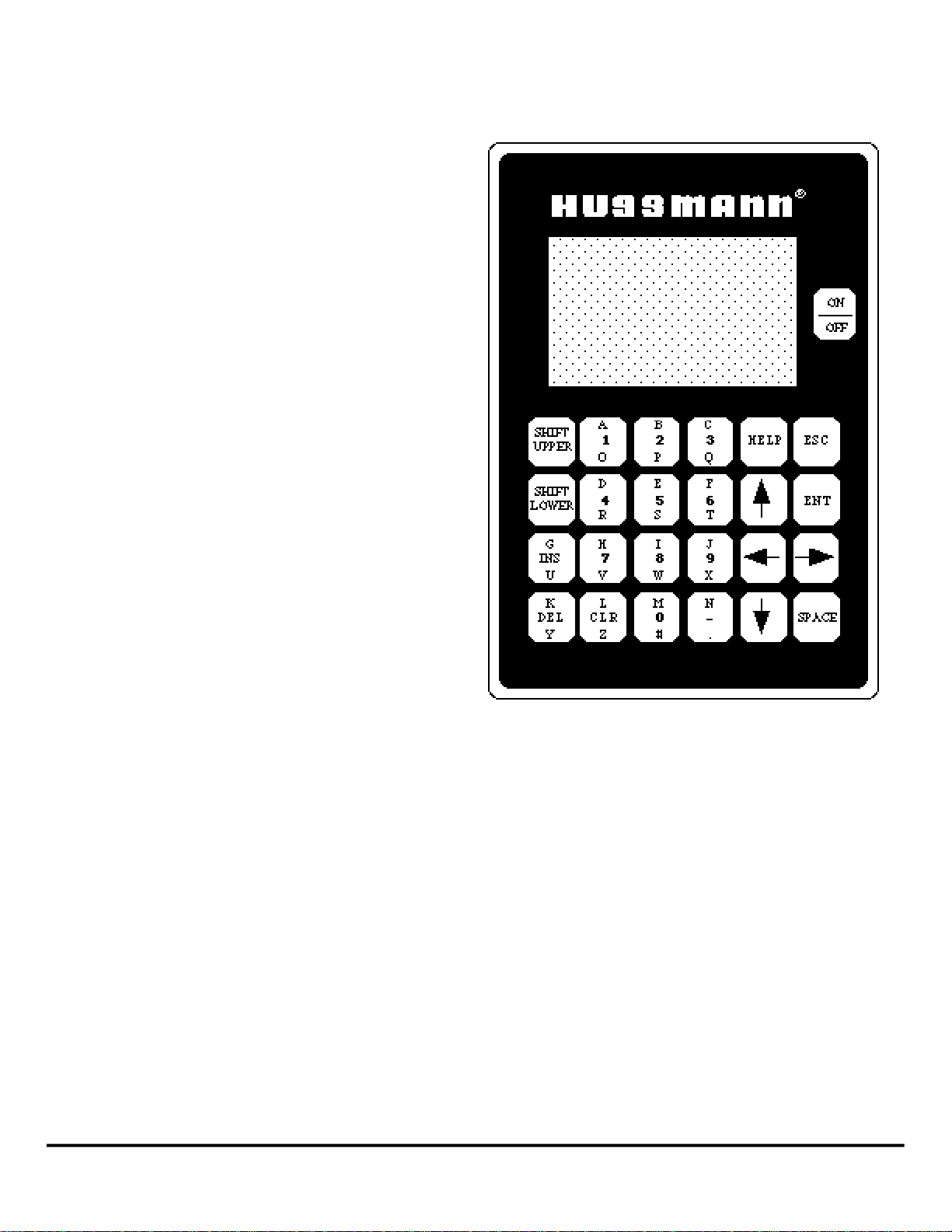
KEY PAD INSTRUCTIONS
Shift Upper – This key is used to key in the top
(red) letters.
Shift Lower – This key is used to key in the
bottom (blue) letters.
NOTE: If either of the above keys is pressed
accidentally, simply press it again to deactivate
it.
INS & DEL – The screen will prompt you
when you need to use these keys.
CLR – Clears last entry
Help – There are no help screens on the current
software.
ESC – Escape; returns you to the previous
menu.
ENT – Enter; you will be prompted as to when
to use this key.
Space – enters a space between letters.
Arrows – These keys move the cursor in the
direction shown. The Right Arrow key is also
used to toggle between functions such as
enable/disable and press/temp.
970307 HUSSMANN CORPORATION • BRIDGETON, MO 63044-2483 (Printed in U.S.A.)
Page 4
P/N 374511B
Page 2
PROTOCOL
™
Hand Held Device
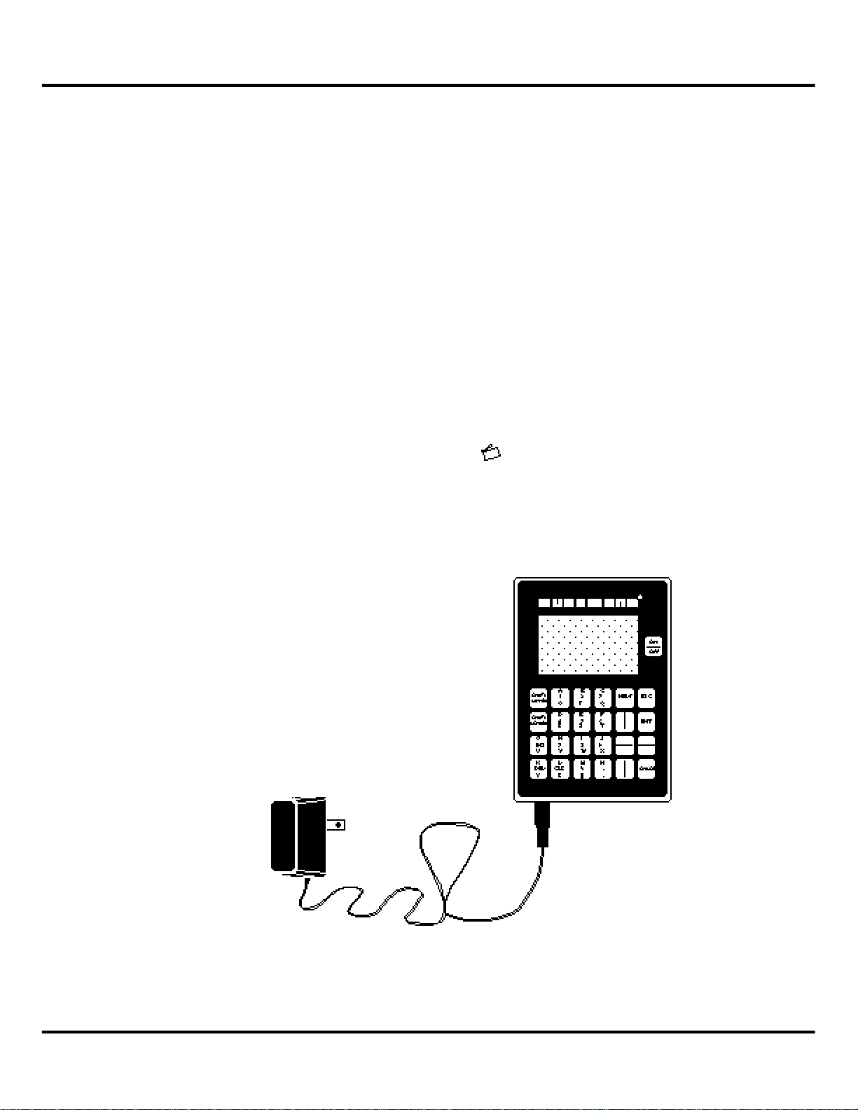
The Hussmann Interface Module may be operated
from either battery power or from a 120V/12VDC
transformer. When using the transformer, connect
Module before plugging in the transformer. The
startup screen will automatically appear.
HUSSMANN
INTERFACE MODULE
(C) 1991 HUSSMANN
CORPORATION
VER 1.30
When battery operated, the Module will shut down
if the key pad has not been used for three minutes.
When a transformer is used, the hand held module
will beep and remain on.
If the battery is too weak to function, the menu
screen will become faint or not come up at all. If
the battery is completely without power, the hand
held module will beep and show an alarm
message. There is also a Low Battery message
that appears at the Main Menu for Protocol™.
Regardless of the power source, if Protocol™ is
not communicating with the hand held module, a
beep will sound and a
appear. If the Protocol™ system is without power,
the hand held module will beep and show an
ALARM message.
COMM ERROR message will
HUSSMANN CORPORATION • BRIDGETON, MO 63044-2483 (Printed in U.S.A.) 970307
Page 5
P/N 374511B
Page 3
PROTOCOL
™
Hand Held Device
SELECT EQU I P M E N T
1 - P ROTO C O L
2-CASE CONTRO L
3-PUMPING STAT I O N
4-FLUID COOLER
P ROTOCOL MAIN MENU
1 - S TATUS MENU
2-CONFIG MENU
3 - D E F ROST MENU
4-MAINT MENU
5-ALARM MENU
L OW BAT T E RY
Following the startup screen, the
SELECT EQUIPMENT screen will appear.
SELECT EQUIPMENT
1-PROTOCOL
2-CASE CONTROL
3-PUMPING STATION
4-FLUID COOLER
Press 1 on the key pad.
The PROTOCOL™ MAIN MENU will appear. This
screen has 5 submenus each of which has its own
submenu(s), see page 4.
Any time a numbered list appears on the menu
screen, pressing the key pad number will take you
to that submenu or function.
Notes:
1) If Case Control is accidentally selected, the
only way to escape is to disconnect power to the
Interface Module.
2) Neither Pumping Station nor Fluid Cooler
information is contained in this manual.
3) L
OW BATTERY appears only if battery voltage
is below normal levels
970307 HUSSMANN CORPORATION • BRIDGETON, MO 63044-2483 (Printed in U.S.A.)
Page 6

P/N 374511B
Page 4
PROTOCOL
™
Hand Held Device
P ROTOCOL MAIN MENU
( _ _) = P
A G E N U M B E RF O RM O R E I N F O R M AT I O N
1- STATUS MENU (07) MAIN STATUS MENU
2- CONFIG MENU (10) CONFIG MENU 1-PRESSURES (07)
3- DEFROST MENU (23) DEFROST MENU 2 - D E F R O S T / T E M PC K T ( 0 8 )
4- MAINT MENU (28) MAINT MENU 1 - S E T THE CLOCK (10) 3 - T E M P E R ATURE MENU (09)
5- ALARM MENU (30) 1 - V I E W / S E T ITEMS (23) 2-SENSOR SETUP ( 11 ) 4 - C O M P RUN METERS (09)
1-FORCE A C O M P O N 2 - C O P Y SCHEDULE (25) 3 - P R O TO C O LS E T U P( 1 5 )
ALARM MENU 2-CLEAR FORCE FLAG 3-ASSIGN OUTPUTS (26) 4-COMM SETUP ( 2 0 ) PRESSURE STAT U S
3-FORCE A C O M P O F F *4-ASSIGN CIRCUITS 5 - L I G H TC O N T R O L( 2 1 ) P 1 P 2
A01- LO SUCTION PRESS 4-FORCE A DEFR ON FOR SPLIT S U C T( 2 7 ) 6 - T E M PC O N T R O L( 2 2 ) S U C T I O N 4 2 0
TIME 01:56 01/21 5-FORCE A DEFR OFF S E T P O I N T 4 0 0
END OF A L A R M S PRESS ENT FOR MORE #COMPS - 1 2 3 4 5 6
6-CLEAR RUN METER ON (X) X X X X
7-FORCE LIGHT O N *This item only appears when unit is configured
8-FORCE LIGHT O F F for split suction option. T E M P E R ATURE STAT U S
**9-CLEAR ALM TA B L E ( F ) S P
* * 0 - R E S E TC O N T R O L T 1 - 4 0 0
T 2 - 4 0 0
T 3 - 4 0 0
* * These options only available with Software Version 2.30 or greater. PRESS ENT FOR MORE
Protocol Control must also be V1.30 or greater T E M P E R ATURE STATUS (CONT)
( F ) S P
T 4 0 0
T 5 0 0
T 6 0 0
T E M P / CIRCUIT #1 T 7 0 0
NAME – CIRCUIT #1 NAME T 8 0 0
S TATUS – REFR
T E M PC T R L – ENABLED A U X I L I A RY S TATUS (EXPA N D E D )
(F) SETPT A7 - 0
AUX #1 22 20 A8 - 0
REFRIG: ON REF 18 A9 - 0
A10 - 0
A 11 - 0
A12 - 0
COMPRESSOR RUN METER
C O M P 1 5 6 H O U R S
C O M P 2 5 7 H O U R S
C O M P 3 5 6 H O U R S
C O M P 4 5 3 H O U R S
C O M P 5 0 H O U R S
C O M P 6 0 H O U R S
HUSSMANN CORPORATION • BRIDGETON, MO 63044-2483 (Printed in U.S.A.) 970307
Page 7

P/N 374511B
Page 5
PROTOCOL
™
Hand Held Device
CONFIG MENU
( _ _) = P
A G EN U M B E R F O RM O R E I N F O R M AT I O N
1- SET THE CLOCK (10) CLOCK SETUP M E N U
2- SENSOR SETUP ( 11 ) SENSOR SETUP M E N U
3- PROTO C O LS E T U P( 1 5 ) P R O TO C O LS E T U PM E N U T I M E - 2 2 : 2 3
4- COMM SETUP ( 2 0 ) COMM SETUP M E N U 1-PRESSURE # 1 (11 ) D AT E - 0 2 : 2 3
5- LIGHT C O N T R O L( 2 1 ) 1-REFR SETUP ( 1 5 ) 2-PRESSURE #2 (12) Y E A R - 9 6
6 - T E M PC O N T R O L( 2 2 ) S TATION NUMBER - 99 2-DEFR SETUP ( 1 8 ) 3 - T E M P # 1 (13) D AY L I G H T- E N A B L E D
BAUD RATE - 19200 3-DESCRIPTION (19) 4 - T E M P # 2 (13) S P R I N G - 02:00 04/27
4-ALARM OUTPUT ( 1 9 ) 5 - T E M P # 3 (13) FA L L - 02:00 10/28
T E M P E R ATURE CONTROL
1-REFR CIRCUIT #1 (22) 1 - T E M P # 4 (13)
2-REFR CIRCUIT #2 (22) LIGHT MENU 2 - T E M P # 5 (13)
3-REFR CIRCUIT #3 (22) 1 - C I R C U I T #1 (21) ALARM OUTPUT 3 - T E M P # 6 (13)
4-REFR CIRCUIT #4 (22) 2 - C I R C U I T #2 (21) O U T P U T NUMBER - X 4 - T E M P # 7 (13)
5-REFR CIRCUIT #5 (22) 5 - T E M P # 8 (13)
6-REFR CIRCUIT #6 (22) LIGHT CIRCUIT #1 6-AUX SENSORS (14)
7-REFR CIRCUIT #7 (22) S TAT U S - E N A B L E D
8-REFR CIRCUIT #8 (22) S TAT U S - E N A B L E D
N A M E - CASE LT S D E S C R I P T I O N CONFIG - REFRIGERAT I O N
REFR CIRCUIT #1 ON T I M E - 0 4 : 0 0 NAME – PROTO C O LN A M E COMPS (TO TAL) - 4
T E M PC N T L - E N A B L E D OFF T I M E - 2 2 : 0 0 CYCLING - ROUND ROBIN
S E T P O I N T - 15 F O U T P U T - 0 8 SUCTION SP - 15 PSI
R AT E - 3 F S P L I T SUCTION - DISABLED
O U T P U TR E L AY - 1 CONFIG DEFROST # COMPRS - 0
# OF CIRCUITS - 3 S P L I TS P - 0 PSI
INTERLOCK - DISABLED
D R I P CYCLE - 0 S AT C O N T R O L - D I S A B L E D
S AT S E T P T - 0 F
S AT D I F F - 0 F
C O N T R O L - T E M P
SPR CONTROL - D I S A B L E D
SPR SP - 0 F
M I X M ATCH SETUP
C O M P R E S S O R S
S T E P 1 2 3 4
1 - 0 1 = X 0 0 0
2 - 0 3 = X X 0 0
3 - 0 6 = 0 X X 0
4 - 1 4 = 0 X X X
:
:
1 6 - 0 0 = 0 0 0
970307 HUSSMANN CORPORATION • BRIDGETON, MO 63044-2483 (Printed in U.S.A.)
Page 8

P/N 374511B
Page 6
PROTOCOL
™
Hand Held Device
DEFROST MENU
( _ _) = P
A G EN U M B E R F O RM O R EI N F O R M AT I O N
1- VIEW/SET ITEMS (23) DEFROST MENU DEFROST CIRCUIT #X
2- COPY SCHEDULE (25)
3- ASSIGN OUTPUTS (26) DEFROST BOARD #1 C I R C U I T N A M E S TAT U S T Y P E O F T I M
*4-ASSIGN CIRCUITS O U T P U T C I R C U I T 1 C I R C U I T #1 NAME D E F R N U M B E R 0 3
FOR SPLIT S U C T( 2 7 ) 1 1 2 C I R C U I T #2 NAME R E F R L E N G T H 1 5
2 2 3 C I R C U I T #3 NAME D AT V S TA RT 0 0 : 0 0
SUCTION A S S I G N M E N T ( 2 7 ) 3 3 4 C I R C U I T #4 NAME N / A A M P E R A G E 0 0
C I R C U I T S U C T I O N 4 4 5 C I R C U I T #5 NAME N / A
1 01 6 C I R C U I T #6 NAME N / A DEFR T E R M E N A B L E D
2 01 DEFROST BOARD #2 7 C I R C U I T #7 NAME N / A 2ND DEFR 0 8 : 1 5
3 01 O U T P U T C I R C U I T 8 C I R C U I T #8 NAME N / A 3RD DEFR 1 6 : 0 0
4 01 5 5
5 01 6 6
6 01 7 7
7 01 8 8 C O P Y DEFROST SCHEDULE
8 01
E X PANSION BOARD C O P Y FROM CIRCUIT - 00
O U T P U T C I R C U I T C O P Y TO CIRCUIT - -
9 0 0
1 0 0 0
11 0 0
1 2 0 0
E X PANSION BOARD DEFROST BOARD #3 DEFROST BOARD #4
O U T P U T C I R C U I T O U T P U T C I R C U I T O U T P U T C I R C U I T
1 3 0 0 1 7 0 0 2 1 0 0
1 4 0 0 1 8 0 0 2 2 0 0
1 5 0 0 1 9 0 0 2 3 0 0
1 6 0 0 2 0 0 0 2 4 0 0
*This item only appears when unit is configured for split suction option.
HUSSMANN CORPORATION • BRIDGETON, MO 63044-2483 (Printed in U.S.A.) 970307
Page 9
P/N 374511B
Page 7
PROTOCOL
™
Hand Held Device
1
2
3
4
5
6
1 2 3 4 5 6
P ROTOCOL MAIN MENU
1 - S TATUS MENU
2-CONFIG MENU
3 - D E F ROST MENU
4-MAINT MENU
5-ALARM MENU
S TATUS MENU
1 - P R E S S U R E S
2 - D E F ROST / TEMP CKT
3 - T E M P E R AT U R E S
4-COMPR RUN METER
PRESSURE STAT U S
P1 P2
SUCTION 0 0
SETPOINT 0 0
# COMPS - 1 2 3 4
ON(X) X X
PRESS ENT FOR MORE
STATUS MENU
1-STATUS MENU
This is a read only menu. It gives you current
operating conditions.
P1 gives the present pressure for the suction manifold.
P2 gives the second suction pressure input.*
Press ESC Key.
SETPOINT is the Suction Set Point for the control
board. The board turns compressors ON and OFF
to maintain this suction pressure.
# COMPS - 1 2 3 4
ON(X) X X
lists the compressor numbers, and indicates
which are running.
Note: Compressors are configured as follows:
Horizontal Protocols
Vertical Protocols
*When Split Suction is installed or when Satellite
compressor is controlled by pressure, P2 can also
be used to monitor high side discharge pressures.
970307 HUSSMANN CORPORATION • BRIDGETON, MO 63044-2483 (Printed in U.S.A.)
Page 10

P/N 374511B
Page 8
PROTOCOL
™
Hand Held Device
S TATUS MENU
1 - P R E S S U R E S
2 - D E F ROST / TEMP CKT
3 - T E M P E R AT U R E S
4-COMPR RUN METER
TEMP CIRCUIT #1
N A M E – CIRCUIT #1 NAME
S TAT U S – R E F R
TEMP CTRL – E N A B L E D
( F ) S E T P O I N T
AUX #1 2 2 20
REFRG – ON REF 7
STATUS MENU (Continued)
2-DEFROST / TEMPCKT
This is a read-only menu. This screen shows the
current operational status of Defrost Circuits and
associated temperatures as provided by Auxiliary
inputs.
NAME gives a description of the case loads for this
defrost circuit.
STATUS indicates whether the defrost circuit is in
defrost (DEFR), refrigeration (REFR), or a
Manually Forced condition (F-DEFR, F-REFR).
T
EMP-CTRL indicates whether temperature control
is available for this circuit. This control feature
allows the refrigeration solenoid to be operated ON
and OFF to maintain a temperature setpoint.
AUX #X provides the actual temperature reading
of the circuit. Note that X will be a number
between 1 and 8 depending upon the Temp/Circuit
number you are currently accessing.
REFRIG is the status of the defrost/refrigeration
relay. ON indicates that power is being fed to the
solenoid. OFF indicates that the solenoid is deenergized.
R
EF is an internal setpoint used by the Temp
Control algorithm. This number will increase up /
decrease down dependent upon the relationship of
the temperature reading (AUX #) and the circuit
setpoint.
Press ENT to view additional circuit information.
Note: Temperature Control is available on Hand
Held Devices V2.40 or greater.
HUSSMANN CORPORATION • BRIDGETON, MO 63044-2483 (Printed in U.S.A.) 970307
Page 11

P/N 374511B
Page 9
PROTOCOL
™
Hand Held Device
AU X I L I A RY MENU
A7 - O P E N
A8 - C L O S E D
A9 - O P E N
A10 - - 40
A11 - 6 0
A12 - - 40
COMPRESSOR RUN METER
C O M P 1 5 6 H O U R S
C O M P 2 5 7 H O U R S
C O M P 3 5 6 H O U R S
C O M P 4 5 5 H O U R S
C O M P 5 0 H O U R S
C O M P 6 0 H O U R S
T E M P E R ATURE MENU
F S P
T1 - - 40 0
T2 - - 40 0
T3 - - 40 0
PRESS ENT FOR MORE
T E M P E R ATURE MENU
F S P
T4 - 0 0
T5 - 0 0
T6 - 0 0
T7 - 0 0
T 8 0 0
PRESS ENT FOR MORE
STATUS MENU (Continued)
3-TEMPERATURE MENU
T1 temperature reading for suction pressure reset
or optional temperature input.
T2 temperature reading for satellite or optional
temperature input.
T3 If split suction is installed, T3 may be factory
set to read head pressure instead of temperature.
Screen will show T3- ___PSI.
If split suction is not installed, T3 is a designated
temperature input; but if you prefer, it can be configured as a pressure input (See page12).
Press ESC Key.
A7
thru
A 1 2
are additional temperature inputs.
These readings may be established by the user as
either ANALOG or DIGITAL under the CONFIGURATION MENU. When set on DIGITAL the read
out will be either OPEN or CLOSED. The digital
setting is applicable to thermostats or auxiliary
contactors.
When the ANALOG setting is used a thermistor is
used to retrieve temperature readings between – 40
and + 120˚F.
When not used the menu will read
DIGITAL. Set on ANALOG, an unused input will
OPEN if set on
produce a – 40.
Press ESC Key.
4-COMPRESSOR RUN METER
COMPRESSOR RUN METER submenu appears.
This menu shows the total number of hours that
each compressor has been operating.
Press ESC to return to S
970307 HUSSMANN CORPORATION • BRIDGETON, MO 63044-2483 (Printed in U.S.A.)
TATUS MENU.
Page 12

P/N 374511B
Page 10
PROTOCOL
™
Hand Held Device
P ROTOCOL MAIN MENU
1 - S TATUS MENU
2-CONFIG MENU
3 - D E F ROST MENU
4-MAINT MENU
5-ALARM MENU
CONFIG MENU
1-SET THE CLOCK
2-SENSOR SETUP
3 - P ROTOCOL SETUP
4-COMM SETUP
5-LIGHT CONTRO L
6-TEMP CONTRO L
CLOCK SETUP MENU
T I M E – 22: 2 3
DAT E – 0 1/ 02
Y E A R – 9 6
DAY L I G H T – E N A B L E D
S P R I N G – 02:00 04/28
FA L L – 02:00 10/27
CONFIG MENU
2-CONFIG MENU
This set of menus is used to make changes in the
Protocol’s configuration. Press 2 on the Keypad
to enter the CONFIG submenu.
1- SET THE CLOCK
Press 1 on the Keypad to enter the CLOCK SETUP
submenu. This screen has 5 fields used to set the
correct time/date.
Hour
2 2
(24-hr clock only)
Minute
Month date
Day date
2 3
0 1
0 2
Year date
9 6
(Last two digits only)
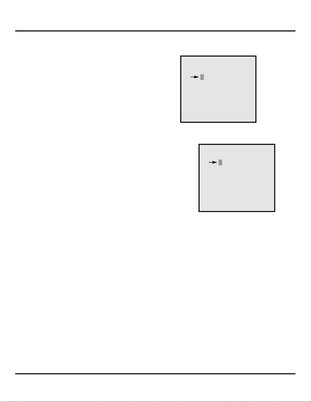
The screen appears with the cursor indicating the
hour field.
22
CURSOR
Press the CLR button. This will change the field
to 00. Then input the correct hour and press ENT.
The cursor will move to the next field. Repeat the
process through each field.
Press ESC to return to the CONFIG MENU.
When enabled, the DAYLIGHT function will auto-
matically adjust the time and year (in case of leap
years) corresponding to changes in TIME and DATE.
HUSSMANN CORPORATION • BRIDGETON, MO 63044-2483 (Printed in U.S.A.) 970307
Page 13

P/N 374511B
Page 11
PROTOCOL
™
Hand Held Device
PRESSURE #1
HI ALARM 40 PSI
LO ALARM 20 PSI
XDCR RANGE - 100 PSI
OFFSET 0 PSI
CONFIG MENU
1-SET THE CLOCK
2-SENSOR SETUP
3 - P ROTOCOL SETUP
4-COMM SETUP
5-LIGHT CONTRO L
6-TEMP CONTRO L
SENSOR SETUP MENU
1-PRESSURE #1
2-PRESSURE #2
3-TEMP #1
4-TEMP #2
5-TEMP #3
CONFIG MENU (continued)
2- SENSOR SETUP
Press 2 on the Keypad to enter the Sensor Setup
Submenu. This screen has 6 menus.
1- PRESSURE #1
Press 1 on the Keypad to enter the Pressure #1
Submenu.
PRESSURE #1 controls the suction pressure for
the Protocol Control. Press the CLR key. Key in
the applicable suction pressure in psig for
ALARM and press ENT. Repeat for LO ALARM.
HI
Pressure Transducers are supplied in one of three
ranges:
0 to 100
0 to 200
0 to 500
Using the key, toggle to the range of the transducer used. Press ENT.
O ffset allows manual calibration for the pressure
t r a n s d u c e r. Manual calibration is achieved by
entering a number between -5 and +5. This number
will then be used to offset the pressure reading by
the entered amount.
WA R N I N G: Impro p e r calibration of the
t r a n s d u c e r could lead to unpre d i c t a b l e
operation of the control. Verify the accuracy of the transducer reading with a
minimum of two gauges.
N o t e : Manual calibration is available on Hand
Held version V2.40 or greater.
Press ESC to return to S
970307 HUSSMANN CORPORATION • BRIDGETON, MO 63044-2483 (Printed in U.S.A.)
E N S O R SE T U P ME N U.
Page 14

P/N 374511B
Page 12
PROTOCOL
™
Hand Held Device
PRESSURE #2
HI ALARM 0 PSI
LO ALARM 0 PSI
XDCR RANGE - 100 PSI
ALARM ENABLED
OFFSET 0 PSI
SENSOR SETUP MENU
1-PRESSURE #1
2-PRESSURE #2
3-TEMP #1
4-TEMP #2
5-TEMP #3
CONFIG MENU (continued)
2- PRESSURE #2
Press 2 on the Keypad to enter the Pressure #2
Submenu.
PRESSURE #2 controls the suction pressure or
Split Suction on the Protocol Control. Press the
C L R k e y. Key in the applicable suction pressure in psig for
Repeat for
L O A L A R M.
H I A L A R M and press E N T.
Pressure Transducers are supplied in one of three
ranges:
0 to 100
0 to 200
0 to 500
Using the key, toggle to the range of the transducer used. Press ENT.
Using the key, move down to the Alarm status
selection. Using the key, toggle
DISABLED. Press ENT.
ENABLED or
O ffset allows manual calibration for the pressure
t r a n s d u c e r. Manual calibration is achieved by
entering a number between -5 and +5. This number
will then be used to offset the pressure reading by
the entered amount.
WA R N I N G: Impro p e r calibration of the
t r a n s d u c e r could lead to unpre d i c t a b l e
operation of the control. Verify the accuracy of the transducer reading with a
minimum of two gauges.
N o t e : Manual calibration is available on Hand
Held version V2.40 or greater.
Press ESC to return to S
HUSSMANN CORPORATION • BRIDGETON, MO 63044-2483 (Printed in U.S.A.) 970307
E N S O R SE T U P ME N U.
Page 15

P/N 374511B
Page 13
PROTOCOL
™
Hand Held Device
TEMPERATURE # 1
SET PT - XX F
HI ALARM - XX F
LO ALARM - XX F
ALARM - ENABLE
ALM DELAY - 30 MIN
CIRCUIT - X
TEMPERATURE # 2
SET PT - XX F
HI ALARM - XX F
LO ALARM - XX F
ALARM - ENABLE
ALM DELAY - 30 MIN
CIRCUIT - X
TEMPERATURE # 3
INPUT MODE - TEMP
SET PT - XX F
HI ALARM - XX F
LO ALARM - XX F
ALARM - ENABLE
ALM DELAY - 30 MIN
CIRCUIT - X
SENSOR SETUP MENU
1-PRESSURE #1
2-PRESSURE #2
3-TEMP #1
4-TEMP #2
5-TEMP #3
CONFIG MENU (continued)
3- TEMP #1
3 - T E M P # 1
allows you to establish set point
and alarm levels for the first temperature
i n p u t .
Press 3 on the Keypad to enter the TEMP #1
Submenu.
The
ALM DELAY is a programmable time delay.
This sets the time it will take before the control
log’s the alarm.
The CIRCUIT - X allows you to attach a defrost
circuit to the temperature input (or vice versa).
When the circuit is in defrost, the HI ALARM will be
ignored.
Press CLR. Key in your selection and
press ENT.
Using the key, toggle ENABLED or DISABLED.
Press ENT.
Press ESC to return to S
E N S O R SE T U P ME N U.
3
4- TEMP #2
Press 4 on the Keypad to enter the TEMP #2
Submenu. Follow instructions above.
5- TEMP #3
Press 5 on the Keypad to enter the
TEMP #3
Submenu.
If split suction is installed, TEMP #3 may be
f a c t o ry set to read head pressure instead of
temperature. This is accomplished by changing
the input mode to Pressure.
If split suction is not installed, TEMP #3 is a
designated temperature input; but if you prefer it
can be factory set as a pressure input.
Using the key, toggle
TEMP or PRESS. Press
ENT.
Press ESC to return to SE N S O R SE T U P ME N U.
4
5
Note: When using T3 for a pressure reading,
remember to place the hardware switch on the
main control board in the pressure position.
970307 HUSSMANN CORPORATION • BRIDGETON, MO 63044-2483 (Printed in U.S.A.)
Page 16

P/N 374511B
Page 14
PROTOCOL
™
Hand Held Device
AUX SENSOR #1
M O D E – D I G I TA L
NAME –
T E R M . S P – C L O S E D
HI ALARM – 0 F
LO ALARM – -40 F
A L A R M – E N A B L E D
SENSOR SETUP MENU
1-TEMP #4
2-TEMP #5
3-TEMP #6
4-TEMP #7
5-TEMP #8
6 - AUX SENSORS
AU X I L I A RY SENSORS
1-AUX SENSOR #1
2-AUX SENSOR #2
3-AUX SENSOR #3
4-AUX SENSOR #4
5-AUX SENSOR #5
6-AUX SENSOR #6
MORE ON NEXT PAGE
AU X I L I A RY SENSORS
1-AUX SENSOR #7
2-AUX SENSOR #8
3-AUX SENSOR #9
4-AUX SENSOR #10
5-AUX SENSOR #11
6-AUX SENSOR #12
CONFIG MENU (continued)
6- AUX SENSORS
Press 6 on the Keypad to enter the Auxiliary
Sensors Submenu.
AUXILIARY SENSORSprovide six temperature
inputs—analog or digital.
Analog for thermistors
Digital for thermostats.
ANALOG SETTING
A N A L O G accommodates temperature readings
between – 40 and + 120˚F. Set on
ANALOG, an
unused input will produce a – 40.
DIGITALSETTING
When set on
OPEN (not in use) or CLOSED.
DIGITAL the read out will be either
Use the key to toggle between ANALOG and
DIGITAL.
Using the ENT key, move down the selections.
Press CLR. Key in your selection and press ENT.
The cursor will move down to the next sensor.
Press ESC to return to AUXILIARY SENSORS MENU.
Press ESC again to return to SENSOR SETUP MENU.
Press ESC again to return to CONFIG MENU.
Note: Aux Sensors 7 through 12 are available
only on Expansion Module.
HUSSMANN CORPORATION • BRIDGETON, MO 63044-2483 (Printed in U.S.A.) 970307
Page 17

P/N 374511B
Page 15
PROTOCOL
™
Hand Held Device
P ROTOCOL SETUP
1-REFR SETUP
2-DEFR SETUP
3 - D E S C R I P T I O N
4-ALARM OUTPUT
C O N F I G - R E F R I G E R AT I O N
COMPS (TOTAL) – 4
CYCLING – ROUND ROBIN
SUCTION SP – 30 PSI
SPLIT SUCT – ENABLED
# COMPRS – 0
SPLIT SP – 0 PSI
C O N F I G - R E F R I G E R AT I O N
SAT CONTROL – DISABLED
SAT SETPT – 0 F
SAT DIFF – 0 F
CONTROL – TEMP
SPR CONTROL – DISABLED
SPR SP – 0 F
CONFIG MENU
1-SET THE CLOCK
2-SENSOR SETUP
3 - P ROTOCOL SETUP
4-COMM SETUP
5-LIGHT CONTRO L
6-TEMP CONTRO L
CONFIG MENU (continued)
3- PROTOCOL SETUP
Press 3 on the Keypad to enter the Protocol Setup
Submenu.
1- REFR SETUP
Press 1 on the Keypad to enter the REFR SETUP
submenu.
This screen programs the Control Board for the
refrigeration parameters:
Number of compressors controlled
Compressor Cycling Algorithm*
Suction Pressure Set Point
Split Suction Control—
E
NABLED/DISABLED
Number of compressors controlled
Split Suction Reset Set Point
To change numeric fields, press the CLR key.
Key in the applicable number. Press ENT. Use
the key, toggle between ENABLED/DISABLED.
Press ENT.
Use the down arrow to get to the next screen
which programs the satellite and Suction Pressure
Reset controls.
Satellite Control — E
N A B L E D/ DI S A B L E D
Satellite Set Point
Satellite Differential
Sat. Control Status — TEMP/PRESS**
**When configured for pressure, the P2 input
serves as the connection point for the transducer.
Suction Pressure Reset status —
ENABLED/DISABLED
Suction Pressure Reset Set Point
To change numeric fields, press the CLR key.
Key in the applicable number. Press ENT. Use
the key, toggle between E
NABLED/DISABLED
and TEMP/PRESS. Press ENT.
Press ESC to return to enter the MixMatch Setup.
Press ESC again to return to P
R O TO C O L SE T U P
ME N U.
*Algorithm options are Round Robin or MixMatch.
NO T E:
C O M P S(TO TA L) is the total number of compressors on the
Protocol units
# C O M P R S is the number of compressors (total) assigned to
split suction
970307 HUSSMANN CORPORATION • BRIDGETON, MO 63044-2483 (Printed in U.S.A.)
Page 18

P/N 374511B
Page 16
PROTOCOL
™
Hand Held Device
M I X M ATCH SETUP
C O M P R S S O R S
S E T U P 1 2 3 4
1 – 0 1 – X 0 0 0
2 – 0 2 – 0 X 0 0
3 – 0 3 – 0 0 X 0
4 – 0 4 – 0 0 0 X
CONFIG MENU (continued)
MixMatch compressor cycling is used when compressors of varying horsepowers have been
installed. This algorithm allows the compressor
horse power to be more closely matched with the
evaporator load
There are 16 available steps for MixMatch
cycling. The additional steps are accessible by
pressing the arrow to view additional screens.
Each step can be programmed by entering anumber between 1 and 63 of the step number. The
Hand Held Device will use this number to display
the compressors selected with an ‘X’and those not
selected with a ‘0.’
The number entered and used by the Hand Held
Device is a binary number. The following example
describes the relationship of the number to compressors. Causion: If you have concerns over this
programming, consult Bridgeton Refrigeration
Engineering.
HUSSMANN CORPORATION • BRIDGETON, MO 63044-2483 (Printed in U.S.A.) 970307
Page 19

P/N 374511B
Page 17
PROTOCOL
™
Hand Held Device
Mixmatch Programming Worksheet
Compr # 1 2 3 4 5 6 Total
HP 4 4 5 6 Total Column
Column Value 1 2 4 8 16 32 HP Value
1 0 0
2 X 4 1
3 X 5 4
4 X 6 8
5 X X 8 3
6 X X 9 6
7 X 10 10
8 X X 11 12
9 X X X 14 11
10 X X X 15 13
11 X X X X 19 14
12 0
13 0
14 0
15 0
16 0
CONFIG MENU (continued)
MIXMATCH PROGRAMMING EXAMPLE
1. Start by making a column for each compressor.
2. The first row must be all 0’s.
A programming worksheet is available at the back
of this manual.
3. Each row will be a step. Each step should
increase rack capacity by the smallest increase in
capacity possible.
4. Use an X in the column for a compressor being
on, and a 0 in the column for a compressor being
Any unused steps must have a zero inserted for the
numbers to prevent unwanted compressors from
running.
o ff. It may help to write the capacity in horsepower
to the right of each row.
5. For each row, add the value of each column
with an X in it and put it on the right of each row.
These are the numbers you enter in for each step.
6. Adjust the X’s and the 0’x for equal runtime on
each compressor.
970307 HUSSMANN CORPORATION • BRIDGETON, MO 63044-2483 (Printed in U.S.A.)
Page 20

P/N 374511B
Page 18
PROTOCOL
™
Hand Held Device
CONFIG - DEFR O S T
# OF CIRCUITS – 7
INTERLOCK – DISABLED
DRIP CYCLE – 0
P ROTOCOL SETUP
1-REFR SETUP
2-DEFR SETUP
3 - D E S C R I P T I O N
4-ALARM OUTPUT
*
CONFIG MENU (continued)
2- DEFR SETUP
Press 2 on the Keypad to enter the Defrost Setup
Submenu.
This screen programs the Control Board for the
defrost parameters:
Number of defrost circuits controlled
Interlock status—
ENABLED/DISABLED
To change numeric fields, press the CLR key.
Key in the applicable number. Press ENT. Use
the key, toggle between E
Press ENT.
Press ESC to return to PROTOCOL SETUP MENU.
Interlock is used when there is only one defrost
circuit programmed into the control. If that one
defrost circuit is electric, all compressors will turn
on during the duration of the defrost. If the single
defrost circuit is gas, the reverse cycle algorithm
will be activated.
NABLED/DISABLED.
*This drip cycle is only used for reverse cycle gas
defrost units.
HUSSMANN CORPORATION • BRIDGETON, MO 63044-2483 (Printed in U.S.A.) 970307
Page 21

P/N 374511B
Page 19
PROTOCOL
™
Hand Held Device
CONFIG - DESCRIPTION
NAME -
P ROTOCOL SETUP
1-REFR SETUP
2-DEFR SETUP
3 - D E S C R I P T I O N
4-ALARM OUTPUT
ALARM OUTPUT
OUTPUT NUMBER – X
P ROTOCOL SETUP
1-REFR SETUP
2-DEFR SETUP
3 - D E S C R I P T I O N
4-ALARM OUTPUT
CONFIG MENU (continued)
3- DESCRIPTION
Press 3 on the Keypad to enter the Description
Submenu.
This screen provides for a 16 character description
of the Protocol unit for user identification on
Hussnet™.
Press the CLR key.
Key in the description . Press Shift Upper to use
the red (upper) letters and Shift Lower to use the
blue (lower) letters.
Press ENT.
Press ESC to return to PROTOCOL SETUP MENU.
Press ESC again to return to CONFIG MENU.
4- ALARM OUTPUT
Press 4 on the Keypad to enter the Alarm Output
Submenu.
The alarm output feature allows one of the 24
available outputs to be energized during the
occurance of any alarm (High/Low Pressure,
High/Low Temp, etc.)
The output number refers to a relay which is wired
into the main Protocol Alarm Relay (AR).
Key in the number (between 1 and 24). Make sure
that the output is available and not being used by
another function (defrost, lighting or temperature
control).
Press ENT.
Press ESC to return to PROTOCOL SETUP MENU.
Press ESC again to return to CONFIG MENU.
970307 HUSSMANN CORPORATION • BRIDGETON, MO 63044-2483 (Printed in U.S.A.)
Page 22

P/N 374511B
Page 20
PROTOCOL
™
Hand Held Device
COMM SETUP MENU
STATION NUMBER – 00
BAUD RATE – 19200
CONFIG MENU
1-SET THE CLOCK
2-SENSOR SETUP
3 - P ROTOCOL SETUP
4-COMM SETUP
5-LIGHT CONTRO L
6-TEMP CONTRO L
CONFIG MENU (continued)
4- COMM SETUP
Press 4 on the Keypad to enter the Communication
Setup Submenu.
This screen provides for assigning each Protocol a
station number for computer identification on
Hussnet™. It also provides baud rate assignment.
The baud rate is the rate at which a computer can
receive data from Protocol. All Protocols must
have the same baud rate in order to communicate.
A baud rate of 19200 is suggested.
Press the CLR key. Key in the number. Press
ENT.
Press ESC to return to CONFIG MENU.
Note: All baud rates will be the same for all
Protocols in a given store. However, the station
numbers must be different.
HUSSMANN CORPORATION • BRIDGETON, MO 63044-2483 (Printed in U.S.A.) 970307
Page 23

P/N 374511B
Page 21
PROTOCOL
™
Hand Held Device
CONFIG MENU
1-SET THE CLOCK
2-SENSOR SETUP
3 - P ROTOCOL SETUP
4-COMM SETUP
5-LIGHT CONTRO L
6-TEMP CONTRO L
LIGHT MENU
1-CIRCUIT #1
2-CIRCUIT #2
LIGHT CIRCUIT #1
S TAT U S – E N A B L E D
N A M E – CASE LT S
O N T I M E – 0 4 : 0 0
O F F T I M E – - 2 2 : 0 0
O U T P U T – - 0 8
CONFIG MENU (continued)
5- LIGHT CONTROL
Press 5 on the Keypad to enter the Light Control
Submenu.
1-CIRCUIT #1
Press 1 or 2 on the Keypad to enter the Circuit #
Submenu.
This screen programs lighting controls on one circuit.
Use the key to toggle between
D I S A B L E D to activate the lighting function. Press
E N A B L E D /
E N T.
Using the ENT key, move down the selections.
Press CLR. Key in your selection and press ENT.
The cursor will move down to the next sensor.
NAME identifies the lights on this circuit.
ONTIME controls when the lights turn on.
OFFTIME controls when the lights turn off.
O
U T P U T controls the relay used by these
PowerLinks™ (lighting circuit breakers).
Press ESC to return to LIGHT MENU.
Press ESC again to return to CONFIG MENU.
970307 HUSSMANN CORPORATION • BRIDGETON, MO 63044-2483 (Printed in U.S.A.)
Page 24

P/N 374511B
Page 22
PROTOCOL
™
Hand Held Device
CONFIG MENU
1-SET THE CLOCK
2-SENSOR SETUP
3 - P ROTOCOL SETUP
4-COMM SETUP
5-LIGHT CONTRO L
6-TEMP CONTRO L
T E M P E R ATURE CONTRO L
1-REFR CIRCUIT #1
2-REFR CIRCUIT #2
3-REFR CIRCUIT #3
4-REFR CIRCUIT #4
MORE ON NEXT PAG E
T E M P E R ATURE CONTRO L
1-REFR CIRCUIT #5
2-REFR CIRCUIT #6
3-REFR CIRCUIT #7
4-REFR CIRCUIT #8
MORE ON NEXT PAG E
REFR CIRCUIT #1
TEMP CONTRO L – E N A B L E D
S E T P O I N T – 15 F
R AT E – 3 F
O U T P U T – - 1
CONFIG MENU (continued)
6- TEMPERATURE CONTROL
Press 6 on the Keypad to enter the Temperature
Control Submenu.
Note: Temperature Control is available on HAND
HELD DEVICE V2.40 or greater.
Press the number of the Temp Refr Circuit you
wish to view or use the and to move to the
appropriate entry and press ENT.
1-REFR CIRCUIT #1
This screen allows configuration for temperature
control of a given circuit.
Use the key to toggle between
D I S A B L E D to activate the control function. Press
E N A B L E D /
E N T.
SETPOINT will be the setting the control will try to
achieve for this circuit.
R
AT E is a number from 1 to 3 which allows the
algorithm to be adjusted for different evaporators.
Arate of 1 establishes a 30 second cycle rate for the
output; 2 establishes a 60 second cycle rate; and
3 establishes a 90 second cycle rate. You may need
to experiment with the rate adjustment in order to
achieve the optimum level of performance.
OUTPUT controls the relay used by the corresponding Defrost Circuit.
Important – Verify the output number between
this temperature circuit and the connected
defrost circuit to ensure proper energizing and
de-energizing of solenoids. Make sure that in
the case of electric defrosts, you haven’t selected the output that operates defrost heaters.
Press ESC to return to T
EMP CONTROL MENU.
Press ESC again to return to CONFIG MENU.
HUSSMANN CORPORATION • BRIDGETON, MO 63044-2483 (Printed in U.S.A.) 970307
Page 25

P/N 374511B
Page 23
PROTOCOL
™
Hand Held Device
D E F ROST MENU
1-VIEW/SET ITEMS
2-COPY SCHEDULE
3-ASSIGN OUTPUTS
4-ASSIGN CIRCUITS
FOR SPLIT SUCT
D E F ROST MENU
C I R C U I T N A M E S TAT U S
1 CIRCUIT #1 NAME R E F R
2 CIRCUIT #2 NAME D E F R
3 CIRCUIT #3 NAME DAT V
4 CIRCUIT #4 NAME R E F R
PRESS ENT TO SET
P ROTOCOL MAIN MENU
1 - S TATUS MENU
2-CONFIG MENU
3 - D E F ROST MENU
4-MAINT MENU
5-ALARM MENU
DEFROST MENU
3-DEFROST MENU
Press 3 on the Keypad to enter the Defrost submenu.
1- VIEW/SET ITEMS
Press 1 on the Keypad to enter the V
IEW/SET ITEMS
Submenu.
This screen shows three columns:
C I R C U I T lists the defrost circuit within the
Protocol. The numbers 1 through 8 are fixed.
NAME refers to the description used to identify
the defrost circuit.
STATUS lists the status of each defrost circuit.
REFR = In refrigeration
DEFR = In defrost
DATV = DE-activated, will not defrost.
TERM = Defrost terminated by temp.
N/A = Not Available or Not Installed
The horizontal arrows are used to activate or deactivate a circuit for defrost control, to force a circuit
in or out of refrigeration or defrost go to the
M
AINTENANCE MENU. Note that the DATV status
permanently disables the defrost function.
Use the vertical arrows to move up and down the
circuit list.
970307 HUSSMANN CORPORATION • BRIDGETON, MO 63044-2483 (Printed in U.S.A.)
Page 26

P/N 374511B
Page 24
PROTOCOL
™
Hand Held Device
D E F ROST MENU
C I R C U I T S Y S T E M S TAT U S
5 0 0 N / A
6 0 0 N / A
7 0 0 N / A
8 0 0 N / A
PRESS ENT TO SET
CIRCUIT #6 - REFR
N A M E DEFR T Y P E - O F T I M
N U M B E R / DAY - 0 3
DEFR LENGTH - 1 5
1ST DEFR - 0 0 : 0 0
A M P E R AG E - 0 0
CIRCUIT #6 - REFR
DEFR T E R M - E N A B L E D
2ND DEFR - 0 8 : 1 5
3ND DEFR - 1 6 : 0 0
END OF DEFRO S T S
DEFROST MENU (continued)
WITH THE CURSOR ON A CIRCUIT NUMBER, press the
ENT key to open that circuit submenu.
CIRCUIT #6 - REFR
Press the CLR key. Key in the applicable Lineup
name. Press ENT. Repeat for NAME, NUMBER/DAY,
DEFR LENGTH and 1ST DEFR HOUR:MINUTES.
Note: To key in name, press Shift Upper to use
the red (upper) letters and Shift Lower to use the
blue (lower) letters.
Three different types of defrost may be used:
Offtime
Gas
Electric
Using the key, toggle to the desired defrost
type. Press ENT.
The amperage number is used for electric
defrosts to turn off compressors and reduce overall amp draw.
Using the key, toggle between
D I S A B L E D for defrost termination. Press E N T.
E N A B L E D /
Note: the termination signal is provided by the
appropriate Auxiliary input (i.e., A
U X1 for CK T1,
AU X2 for CK T2, …).
The remaining defrosts are listed. The control
panel spaces the number of defrosts evenly
across a 24 hour day. To customize the defrost
schedule, press the C L R k e y. Key in the applicable hour for defrost start. (Defrost times can be
entered on the quarter hour – :00, :15, :30 or
:45.) Press E N T. Press the C L R k e y. Key in
the applicable minute for defrost start. Press
E N T.
Press ESC to return to previous screen and to
return to V
IEW / SET ITEMS MENU.
Press ESC again to return to DEFROST MENU.
HUSSMANN CORPORATION • BRIDGETON, MO 63044-2483 (Printed in U.S.A.) 970307
Page 27

P/N 374511B
Page 25
PROTOCOL
™
Hand Held Device
D E F ROST MENU
1-VIEW/SET ITEMS
2-COPY SCHEDULE
3-ASSIGN OUTPUTS
4-ASSIGN CIRCUITS
FOR SPLIT SUCT
COPY DEFROST SCHEDULE
COPY FROM CIRCUIT - 0 0
COPY TO CIRCUIT -
DEFROST MENU (continued)
2- COPY SCHEDULE
Press 2 on the Keypad to enter the Copy Schedule
Submenu.
Press the CLR key. Key in the applicable Circuit
# for Copy From. Press ENT.
Press the CLR key. Key in the applicable Circuit
# for Copy to. Press ENT.
Press ESC to return to D
EFROST MENU.
970307 HUSSMANN CORPORATION • BRIDGETON, MO 63044-2483 (Printed in U.S.A.)
Page 28

P/N 374511B
Page 26
PROTOCOL
™
Hand Held Device
D E F ROST BOARD #1
O U T P U T C I R C U I T
1 0 0
2 0 0
3 0 0
4 0 0
D E F ROST BOARD #2
O U T P U T C I R C U I T
5 0 0
6 0 0
7 0 0
8 0 0
E X PANSION BOA R D
O U T P U T C I R C U I T
9 0 0
1 0 0 0
1 1 0 0
1 2 0 0
E X PANSION BOA R D
O U T P U T C I R C U I T
1 3 0 0
1 4 0 0
1 5 0 0
1 6 0 0
D E F ROST BOARD #3
O U T P U T C I R C U I T
1 7 0 0
1 8 0 0
1 9 0 0
2 0 0 0
D E F ROST BOARD #4
O U T P U T C I R C U I T
2 1 0 0
2 2 0 0
2 3 0 0
2 4 0 0
D E F ROST MENU
1-VIEW/SET ITEMS
2-COPY SCHEDULE
3-ASSIGN OUTPUTS
4-ASSIGN CIRCUITS
FOR SPLIT SUCT
DEFROST MENU (continued)
3- ASSIGN OUTPUTS
Press 3 on the Keypad to enter the Assign Outputs
Submenu.
Press ENT to move the cursor to the value to be
changed. Press the CLR key.
Key in the applicable Circuit #. Press ENT.
Electric defrost circuits will typically require two
outputs (one for solenoid and one for heater control); while offtime and gas defrost circuits require
only one.
Press ESC to return to D
EFROST MENU.
HUSSMANN CORPORATION • BRIDGETON, MO 63044-2483 (Printed in U.S.A.) 970307
Page 29

P/N 374511B
Page 27
PROTOCOL
™
Hand Held Device
D E F ROST MENU
1-VIEW/SET ITEMS
2-COPY SCHEDULE
3-ASSIGN OUTPUTS
4-ASSIGN CIRCUITS
FOR SPLIT SUCT
SUCTION ASSIGNMENT
C I R C U I T S U C T I O N
1 0 0
2 0 0
3 0 0
4 0 0
SUCTION ASSIGNMENT
C I R C U I T S U C T I O N
5 0 0
6 0 0
7 0 0
8 0 0
DEFROST MENU (continued)
4- ASSIGN CIRCUITS
FOR SPLIT SUCTION
NOTE: This item only appears when the unit is
configured for the split suction option.
Press 4 on the Keypad to enter the Assign Circuits
For Split Suction Submenu.
Press ENT to move the cursor to the value to be
changed. Press the CLR key.
Press the left and right arrow keys to toggle
between suctions #1 and #2.
Press ESC to return to D
EFROST MENU.
Press ESC again to return to PROTOCOL MAIN
MENU.
970307 HUSSMANN CORPORATION • BRIDGETON, MO 63044-2483 (Printed in U.S.A.)
Page 30

P/N 374511B
Page 28
PROTOCOL
™
Hand Held Device
P ROTOCOL MAIN MENU
1 - S TATUS MENU
2-CONFIG MENU
3 - D E F ROST MENU
4-MAINT MENU
5-ALARM MENU
MAINT MENU
1-FORCE A COMP ON
2-CLEAR FORCE FLAG
3-FORCE A COMP OFF
4-FORCE A DEFR ON
5-FORCE A DEFR OFF
PRESS ENT FOR MORE
FORCE A COMP ON
ENTER NUMBER - 0
FORCE A COMP OFF
ENTER NUMBER - 0
FORCE A DEFR ON
ENTER NUMBER - 0
FORCE A DEFR OFF
ENTER NUMBER - 0
1
3
4
5
MAINT MENU
4- MAINT MENU
Press 4 on the Keypad to enter the Maintenance
Menu Submenu. This screen has one function,
four menus, and a second page.
The functions is: 2-CLEAR FORCE FLAG
Simply press 2 to activate clear function.
Press Numbers 1, 3, 4, 5 on the Keypad to enter
the Submenu. Key in compressor or defrost
circuit #. Press ENT.
The time limit on C
OMPRESSORS forced on/off is
20 minutes. After time limit expires, compressors
return to normal operation.
The time limit for DEFROST CIRCUITS forced on is
a function of the defrost length programmed for
that circuit. For circuits forced out of defrost, operation is suspended for the current defrost only.
Normal operation resumes at the next scheduled
defrost.
Press ESC to return to M
HUSSMANN CORPORATION • BRIDGETON, MO 63044-2483 (Printed in U.S.A.) 970307
AIN MENU.
Page 31

P/N 374511B
Page 29
PROTOCOL
™
Hand Held Device
MAINT MENU
6-CLEAR RUN METER
7-FORCE LIGHT ON
8-FORCE LIGHT OFF
9-CLEAR ALM TABLE
0-RESET CONTROL
FORCE A LIGHT ON
ENTER NUMBER - 0
FORCE A LIGHT OFF
ENTER NUMBER - 0
RESET CONTRO L
ENTER NUMBER - 0
7
8
0
4- MAINT MENU
Press 4 on the Keypad to enter the Maintenance
Menu Submenu.
Press ENT to move to the second page.
This screen has two functions and three menus.
The two functions are:
6-CLEAR RUN METER
9-CLEAR ALARM TABLE
Simply press 6 or 9 to activate clear function.
Press Numbers 7, 8, 0 on the Keypad to enter the
Submenu. Key in compressor or defrost circuit #.
Press ENT.
Press ESC to return to M
Options 9 and 0 are available with Software Version 2.30 or greater. Protocol™ Control
must be V1.30 or greater
AIN MENU.
970307 HUSSMANN CORPORATION • BRIDGETON, MO 63044-2483 (Printed in U.S.A.)
Page 32

P/N 374511B
Page 30
PROTOCOL
™
Hand Held Device
P ROTOCOL MAIN MENU
1 - S TATUS MENU
2-CONFIG MENU
3 - D E F ROST MENU
4-MAINT MENU
5-ALARM MENU
ALARM MENU
A01 - LO SUCTION PRES
TIME 01:56 01/21
END OF ALARMS
ALARM MENU
5-ALARM MENU
Press 5 on the Keypad to enter the A l a r m
Submenu.
This screen lists the last 16 alarms giving the type,
time (24 hour clock) and date of each. Alarms
may be continued on the next screen. To read continued alarms, Press ENT.
The screen will read END OF ALARMS after last
alarm reading.
Press ESC to return to MAIN MENU. When exiting
the menu, you will be prompted whether to clear
the alarms. Press the CLR Key to remove the current alarm.
Types of Alarms
•POWER DOWN
•POWER RESET
•HI TEMPALARM – AUXILIARYINPUT
•MODULES IN BACKUP MODE
•HIGH SUCTION PRESSURE*
•LOW SUCTION PRESSURE*
•HIGH HEAD PRESSURE
•LOW HEAD PRESSURE
•ALL COMPRESSORS OFF ALARM*
•LO TEMPALARM – AUXILIARY INPUT
•HI ALARM T1
•LO ALARM T1
•HI ALARM T2
•LO ALARM T2
•HI ALARM T3
•LO ALARM T3
•MEMORYCHECK ERROR
•DEFROST MEMORY CHECK ERROR
•HI ALARM T4
•LO ALARM T4
•HI ALARM T5
•LO ALARM T5
•HI ALARM T6
•LO ALARM T6
•HI ALARM T7
•LO ALARM T7
•HI ALARM T8
•LO ALARM T8
*Denotes switchback. Control operated by mechanical low pressure switch. No defrosts occur during
s w i t c h b a c k .
HUSSMANN CORPORATION • BRIDGETON, MO 63044-2483 (Printed in U.S.A.) 970307
Page 33

P/N 374511B
Page 31
PROTOCOL
™
Hand Held Device
Mixmatch Programming Worksheet
Compr # 1 2 3 4 5 6 Total
HP Total Column
Column Value 1 2 4 8 16 32 HP Value
1
2
3
4
5
6
7
8
9
10
11
12
13
14
15
16
Mixmatch Programming Worksheet
Compr # 1 2 3 4 5 6 Total
HP Total Column
Column Value 1 2 4 8 16 32 HP Value
1
2
3
4
5
6
7
8
9
10
11
12
13
14
15
16
970307 HUSSMANN CORPORATION • BRIDGETON, MO 63044-2483 (Printed in U.S.A.)
Page 34

®
CORPORATION
CONDENSING UNITS AND REFRIGERATION SYSTEMS
This wa r ranty is made to the original purchaser user and is N OT T R A N S F E R A B L E.
ONE YEAR LIMITED WA R R A N T Y
1 . Hussmann Cor p o ration wa r rants the new Hussmann Equipment, and all parts thereof, to be free of defects in mate-
rial and wo rkmanship at time of purchase.
2 . Hussmann's obligation under this w a r ranty shall be limited to repairing or exchanging free of charge any part or
p a rts of the system or unit, supplied by Hussmann Corp o ration, Bridgeton, Missouri, F. O. B. fa c t o ry or the nearest
a u t h o ri zed parts depot, which may prove to be defe c t i ve within one year from date of original installation (not to
exceed fifteen months from date of shipment from fa c t o ry) and which is proven to the satisfaction of Hussmann to
be thus defe c t i ve.
3 . THIS WARRANTY TO REPAIR OR REPLACE ABOVE RECITED, IS THE ONLY WARRANTY EXPRESSED, IMPLIED,
OR STAT U TO RY MADE BY HUSSMANN WITH RESPECT TO THE EQUIPMENT ABOVE LISTED, AND IT NEITHER
ASSUMES NOR AUTHORIZES ANY PERSON TO ASSUME FOR IT, ANY OTHER OBLIGATION OR LIABILITY IN
CONNECTION WITH THE SALE OF SAID EQUIPMENT OR ANY PA RT T H E R E O F.
E X C L U S I O N S
1 . THIS WARRANTY SHALL NOT APPLY TO LOSS OF FOOD DUE TO FAILURE FOR ANY REASON.
2 . HUSSMANN SHALL NOT BE LIABLE:
a . For any repairs or replacements made by bu yer without written consent of Hussmann, or when equipment is
installed or operated in a manner contra ry to printed instructions cove ring installation and service which accompanied or was supplied for such equipment.
b. For any damages, dela y s, losses, direct or consequential, caused by def e c t s, nor for damages caused by short
or reduced supply of material, fire, flood, str i ke s, acts of God or circumstances beyond its control.
c . When the failure or defect of any part or parts is incident to ordinary w e a r, accident, abuse or misuse, or when
the serial number of the equipment has been removed, defaced, altered or tampered with.
d . When equipment is operated on low or improper vo l t a g e s, or put to use other than normally recommended by
H u s s m a n n .
e. For payment of any removal or installation charges of w a r ranted part s.
f. For payment of refri g e rant losses for any reasons.
g . When equipment is moved to an address other than the original installation.
ADDITIONAL FOUR YEAR PROTECTION PLAN FOR MOTOR/COMPRESSOR ASSEMBLY ONLY
(OPTIONAL – MUST BE PURCHASED PRIOR TO SHIPMENT
OF CONDENSING UNIT OR REFRIGERATION SYSTEM)
In addition to the above One Year Wa r ranty on said Condensing Unit or Refri g e ration System, Hussmann Corp o ra t i o n ,
a grees to repair or replace the motor compressor only, with a motor compressor of like or author i zed similar capacity
( F. O. B. Fa c t o ry or nearest Vendor author i zed parts depot), at any time during this four year period immediately fo l l owing the ex p i ration of the above one year w a r ra n t y, if proven to the satisfaction of Hussmann,
that the compressor is inoper a t i ve due to defects in f a c t o ry w o rkmanship or material under normal use and
s e rv i c e. Hussmann reserves the right to inspect the job site, installation and reason for f a i l u r e.
The Four Year Protection Plan does not include controls, relay, capacitor, ov e rload protector, va l ve plates, oil
p u m p s, gaskets or any e x t e rnal part on the motor compressor replaceable in the field, or any other part of the
r e f ri g e ration system.
GENERAL CONDITIONS
No service or labor charges incidental to the replacement of parts during the First Year Wa r ranty and the succeeding
four years under the protection plan will be allowed under the terms thereof.
All claims must be presented and completed within six months from date of fa i l u r e. Claims must be accompanied by
the vendor invoice and credit showing model and serial number of compressor that failed and the new replacement
c o m p r e s s o r. Records should be maintained with copies of above documents to show any inwa r ranty replacements within the One Year Wa r ranty and should be submitted along with claim to show original compressor model and serial n u mb e r.
HUSSMANN CORPORAT I O N
8/92
B r i d ge t o n , Missouri 63044 – U. S . A .
 Loading...