

Page 1
MAXI-140
Operator’s Manual
P/N 31033596_B
01 June 2007
™
Page 2

These merchandisers are manufactured to meet ANSI / National Sanitation Foundation (NSF®) Standard #7 Type II
requirements. Proper installation is required to maintain certification. Near the serial plate, each case carries a label
identifying the type of application for which the case was certified.
ANSI/NSF-7 Type II – Display Refrigerator / Freezer ( Beverage Cooler)
Intended for 80°F / 55%RH Ambient Application
This equipment is intended for the storage and display of
nonpotentially hazardous, bottled or canned products only.
Copyright Notice
Hussmann and Safe-NET are trademarks of Hussmann Corporation,
Chill Chamber is a trademark of Anheuser-Busch, Inc.
EPH
Page 3
SAFETY FIRST!
Before installing, read and understand the
operating manual. Any damage caused by not
following directions given in this manual is outof-warranty.
Contact
To request technical assistance with your
Chill Chamber, or to place a service call,
please phone Hussmann’s call center at
1 (800) 504-4828.
LOCATION
Chill Chambers are designed for a protected
environment, out of direct sun or rain. Placing
the unit near heat sources (ovens, grills, etc.) or
in direct sun will adversely affect performance.
Unusual ambient conditions can be handled by
changing settings in the Safe-NET controller.
Temperatures of 80°F (27°C) and less than
55% R.H. are considered normal ambient
conditions.
The merchandiser will not operate properly
in environments of extreme temperature and
humidity [above 80°F (27°C) and 55% relative
humidity]. Performance issues resulting from
poor local conditions are out-of-warranty.
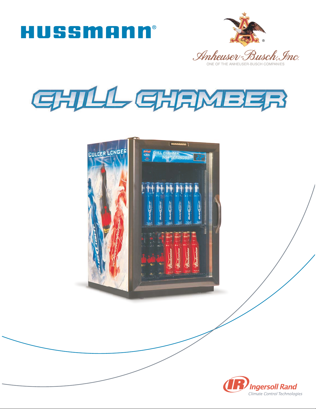
The merchandiser must have a minimum 5-inch
(13 cm) ventilation space at the back, on each
side, and below the door in front. Top must be
open.
©2007 HUSSMANN CORPORATION • BRIDGETON, MO 63044-2483 U.S.A.
U.S. & CANADA 1-800-504-4828 • WWW.CHILLCHAMBER.HUSSMANN.COM
1
P/N 31033596_B
01 June 2007
™
MAXI-140
™
MAXI-140
™
MAXI-140
™
MAXI-140
™
MAXI-140
™
To reduce the risk of fire, electrical shock or
injury when using your Chill Chamber:
• Always use a dedicated circuit with the
Amperage stated on the unit.
• Plug into an outlet designed for the plug.
• Do not use an adapter.
• Do not overload the circuit.
• Disconnect power before servicing.
• Replace any damaged power cord.
• Never turn off by pulling on the power cord.
• Unit must have electrical ground at all times.
• Never connect the ground wire directly to the
neutral wire or connect to gas, water,
telephone, drain pipe, lightning rod, etc.
• Do not damage the refrigeration system.
• Do not use any mechanical device or other
means to speed the defrost process, except
as recommended by the manufacturer.
• Unplug the Chill Chamber before cleaning.
• Do not store or use toxic or dangerous
chemical products inside the case.
• Do not use electrical devices in the Chill
Chamber unless recommended by the
manufacturer.
• Use two or more people to move a unit.
• Keep packing materials away from children.
CAUTION
!
We reserve the right to change or revise specifications and product design in
connection with any feature of our products. Such changes do not entitle the
buyer to corresponding changes, improvements, additions or replacements
for equipment previously sold or shipped.
5-inch (13 cm) Required Ventilation Minimum
OPEN
NOTHING ABOVE
Page 4
Condensation may form on external parts
when the merchandiser is used in high relative
humidity. Use a soft cloth to remove moisture.
The floor or counter must be flat to facilitate
leveling and to avoid problems with door sealing or abnormal noises. The floor, or counter,
must support the weight of a fully loaded
Chill Chamber. A fully loaded MAXI-140
weighs about 210 lb (95-kg).
INSPECTION
All equipment should be thoroughly examined
for shipping damage before and during the
unloading.
Each Chill Chamber is carefully inspected at
our factory. Any claim for loss or damage must
be made to the carrier. The carrier will provide
any necessary inspection reports and/or claim
forms.
Apparent Loss Or Damage
If there is an obvious loss or damage, it must
be noted on the freight bill or express receipt
and signed by the carrier’s agent; otherwise,
carrier may refuse claim.
Concealed Loss Or Damage
When loss or damage is not apparent until after
equipment is uncrated, retain all packing materials and submit a written request to the carrier
for inspection, within 15 days.
UNCRATE
Use the appropriate equipment to safely lift
and move the Chill Chamber to the preferred
location in your business.
Carefully remove the shipping box. Avoid
scratching the Chill Chamber.
Recycle packing materials whenever possible.
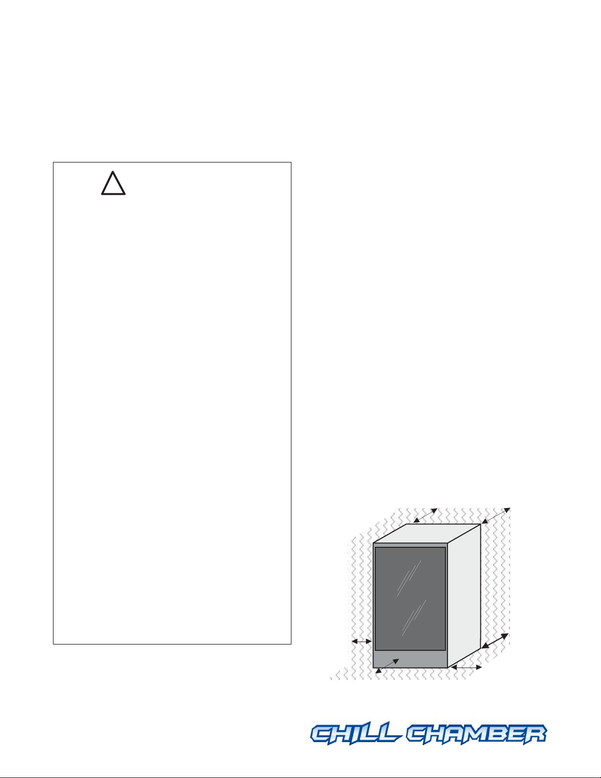
Remove Shipping Legs so the MAXI-140 Chill
Chamber base can be sealed to counter.
After leveling, use field-supplied FDA foodgrade silicone sealant* to seal the gap between
the base of the MAXI-140 and the countertop.
©2007 HUSSMANN CORPORATION • BRIDGETON, MO 63044-2483 U.S.A.
U.S. & CANADA 1-800-504-4828 • WWW.CHILLCHAMBER.HUSSMANN.COM
2
P/N 31033596_B
01 June 2007
MAXI-140
IMPORTANT:
The MAXI-140 Chill Chamber must remain
upright at all times. Do not tilt more than
30 degrees from vertical at any time.
Remove Shipping Legs
Front and Back
* Examples of FDA food grade silicone sealant:
Permatex Inc.
Silicone RTV Sealant for Food Zone
Henkel Loctite Corp.
RTV Silicone Adhesive Sealants for Food Zone,
"Loctite Superflex"
Silicone Sealant for Food Zone,
"Loctite Silatech"
General Electric Co.
RTV Silicone Rubber Adhesive Sealant for Food Zone,
"RTV 102, RTV 103, RTV 108, RTV 112, and others"
DOW Corning Corp.
100% Silicone Sealant for Food Zone,
"Dow Corning Commercial Grade"
Industrial Grade Silicone for Food Zone,
"Dow Corning 700"
. RTV Silicone Sealant for Food Zone,
"Dow Corning HVAC/R"
Page 5
©2007 HUSSMANN CORPORATION • BRIDGETON, MO 63044-2483 U.S.A.
U.S. & CANADA 1-800-504-4828 • WWW.CHILLCHAMBER.HUSSMANN.COM
3
P/N 31033596_B
01 June 2007
™
MAXI-140
Optional Leg Kit
To maintain NSF standards of cleanability
when sealing cannot be done, Hussmann offers
optional leg kits that raises the MAXI-140
four or six inches. Directions are included with
the optional leg kit.
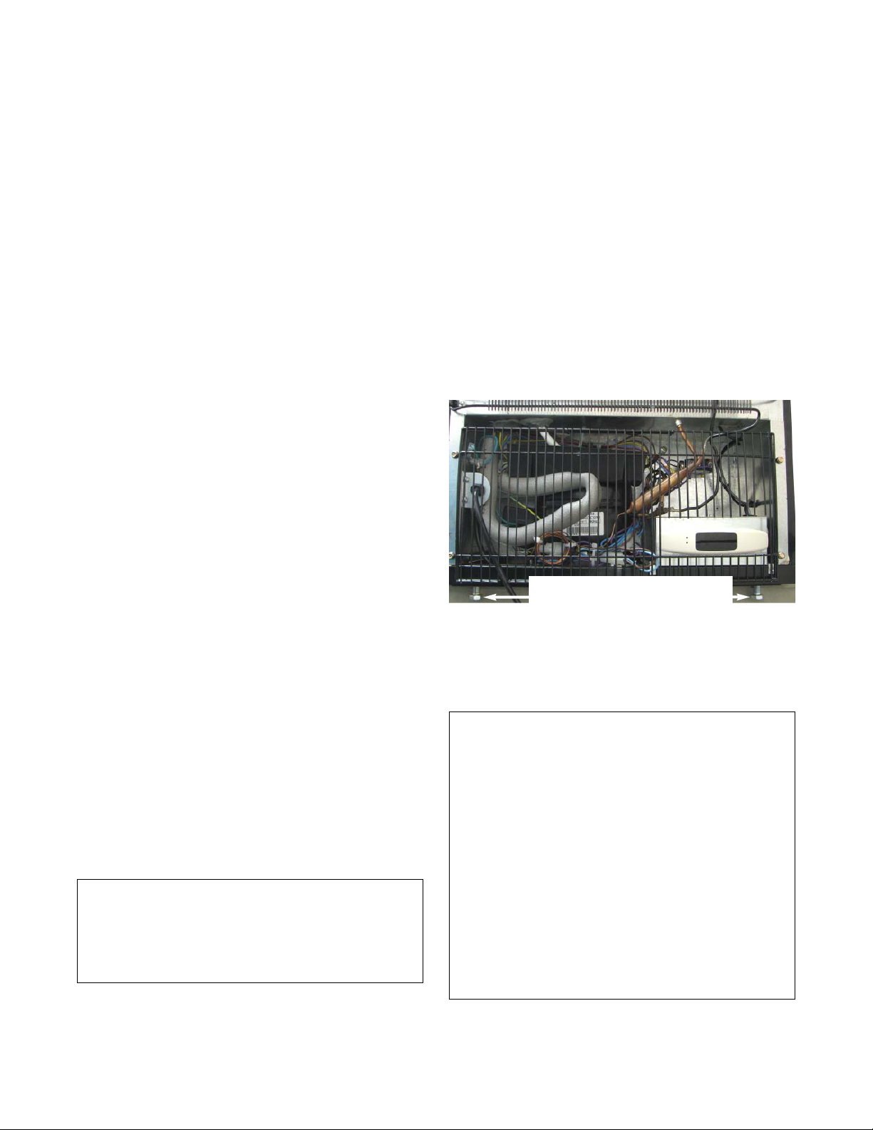
LEVEL
Chill Chambers must be level front-to-back
and side-to-side to operate at peak efficiency.
Shimming may be necessary. Ensure all sides
are firmly supported. Use care when shimming
legs.
PLUG IN
Put the Chill Chamber on its own dedicated
electrical circuit with ground. 12AWG is the
minimum size wire acceptable.
• The MAXI-140
requires a dedicated
15 Amp circuit with
grounded wall receptacle
(NEMA 5-15P)
• Do not use extension
cords. Never use adapters.
• If in doubt, call an electrician.
Electrical requirements for the merchandiser
are stated on the serial plate attached to the
unit.
If the power supply oscillates beyond the range
given in the preceding table, install a voltage
regulator.
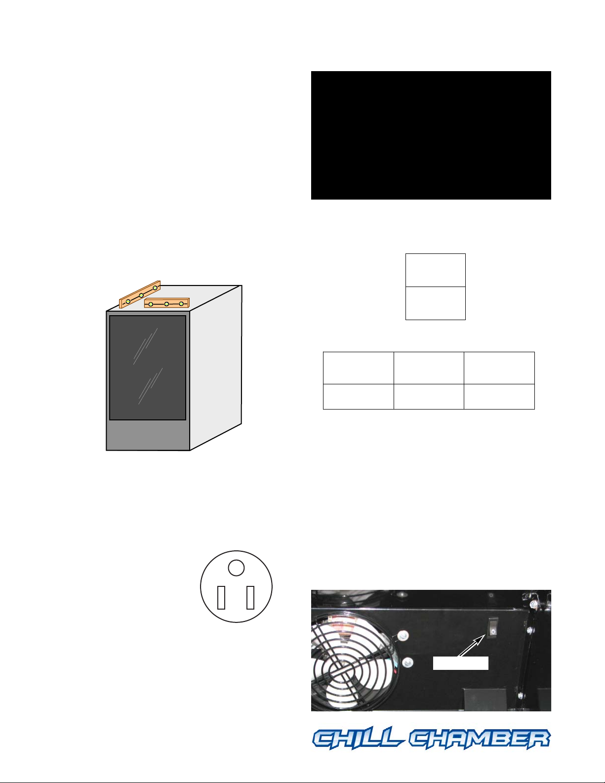
Light Switch
The MAXI-140 Chill Chamber light switch is
located on the right rear of the interior top
panel. It controls the exterior canopy light;
LED lighting is
ON at all times.
™
MAXI-140
™
MAXI-140
™
MAXI-140
™
MAXI-140
™
NEMA 5-15P
MAXI-140
MAXI-140
1000 VA
Nominal
Voltage
Minimum
Voltage
Maximum
Voltage
120 108 132
Light switch
IMPORTANT:
After leveling, wait at least 30 minutes
before turning on power to the Chill
Chamber to allow any oil residue to return
to the compressor.
Oil not in the compressor at start up may
cause permanent damage not covered by
warranty.
Page 6
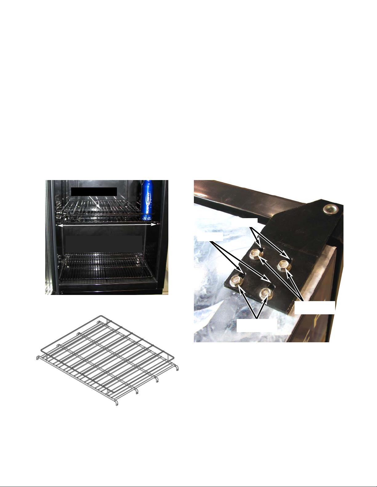
INSTALL SHELVES
The MAXI-140 comes standard with
one fixed wire shelf with dividers for 16oz.
aluminum bottles and one removable flat wire
shelf for 16oz. aluminum bottles.
The removable lower shelf must be placed flush
against the back to maintain proper air flow
and product temperature.
DOOR HINGES
The MAXI-140 Chill Chamber door is not
self-closing.
The top door hinge has slots that allow the
door to be adjusted if the gasket doesn’t seal
completely.
Use a nut driver to loosen the four hex-head
screws just enough to allow the hinge to move
backward which will tighten the door seal.
©2007 HUSSMANN CORPORATION • BRIDGETON, MO 63044-2483 U.S.A.
U.S. & CANADA 1-800-504-4828 • WWW.CHILLCHAMBER.HUSSMANN.COM
4
P/N 31033596_B
01 June 2007
MAXI-140
Shelf Fasteners
Removable Lower Shelf
with Product Stop to Rear
Fixed Upper Shelf
MAXI-140 Upper Shelf
Slots
Slots
Top of MAXI-140
Loosen Screws
Loosen Screws
Page 7
SET Safe-NET TIME
Safe-NET is the electronic controller that
regulates the cooling system. Before Safe-NET
can operate correctly, the internal clock must
be set. This will allow it to regulate the system
for defrost at convenient times of the day
around your location’s schedule — when you
are not at the busiest serving times.
The Chill Chamber’s Safe-NET comes preset
with two defrosts per day. In most situations
this will be enough defrosts unless the unit is
operated in non-air conditioned environments
or high humidity locations.
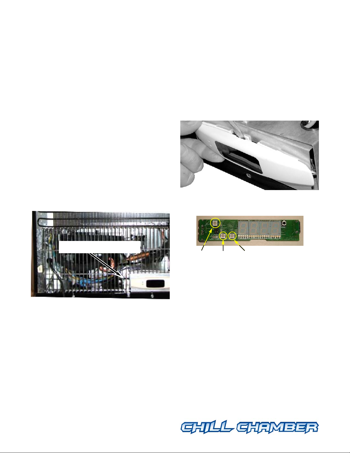
The Safe-NET on the MAXI-140 is located
behind the back grille below the condenser coil.
When you plug in the Chill Chamber you
should see the text “Safe-NET” scroll across
the display.
• Open the Safe-NET controller using a small
flat blade screwdriver to pop off the oval cover
(this may be tight).
• Plug in the MAXI-140. Be careful of
moving parts in the compressor compartment.
• You will see three buttons on the control
board as shown in this photo.
The SELECT button is used to scroll through
menus, and to edit/confirm values. Use the UP
or DOWN button to move to the next item in
the menu or change the value of a parameter.
Three Button Rules
• Always start by pushing and releasing the
SELECT button, watch what is displayed.
Which menu are you in?
— StUP — CLOC — DEFr — tEM —
VALv — DiSP — and cycles back to StUP
©2007 HUSSMANN CORPORATION • BRIDGETON, MO 63044-2483 U.S.A.
U.S. & CANADA 1-800-504-4828 • WWW.CHILLCHAMBER.HUSSMANN.COM
5
P/N 31033596_B
01 June 2007
™
MAXI-140
™
MAXI-140
™
MAXI-140
™
MAXI-140
™
MAXI-140
™
Safe-NET Controller
SELECT
Button
UP
Button
DOWN
Button
Page 8

• Press and release the SELECT button until
you are in the proper menu. Once in the proper
menu press the UP or DOWN button to enter
the menu and to scroll through the menu.
• Once at the menu item that you want, press
the SELECT button until the item flashes
between the value and the title. You may have
to press the SELECT button more than once
to get the item to flash.
• Then press the UP or DOWN button to
change the item.
• Remember to push the SELECT button to
save the item.
• Pressing the UP and DOWN buttons at the
same time acts as an escape to go back out of
the menus.
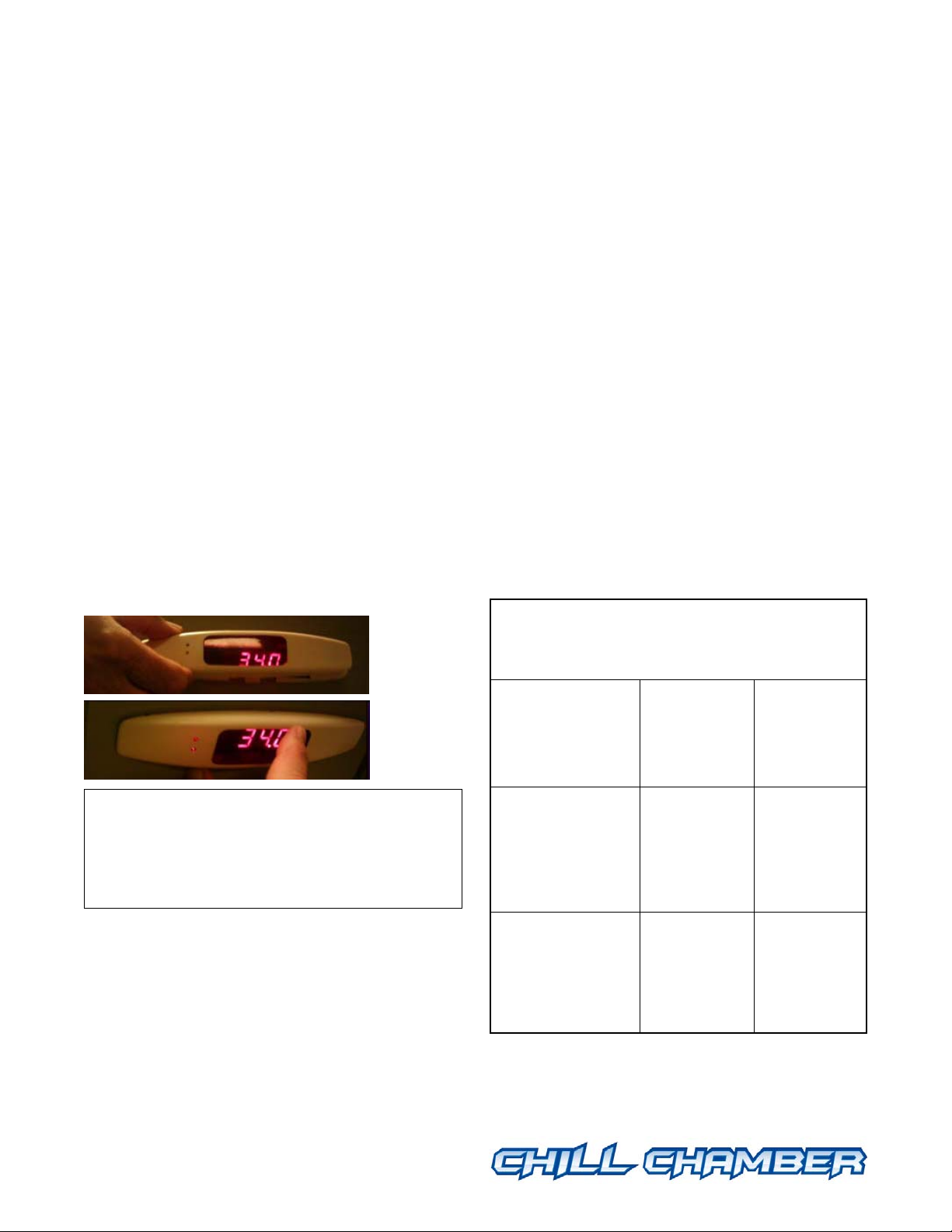
Set the Clock
• Press the UP and DOWN buttons at the same
time to get to the temperature reading / default
display.
• Press the SELECT button until you see CLOC.
• Press UP once, then DOWN once, and then
SELECT.
• With minutes flashing, use the UP or DOWN
button until the correct minutes are displayed,
then press SELECT. Hours should flash.
• With hours flashing, use the UP or DOWN
button until the correct hour is displayed
(Safe-NET uses a 24-hour, or military, clock
where 12 is noon).
• Press SELECT and the clock has been set.
• The clock will automatically return to main
display. The internal real-time clock will retain
its time setting for at least one week if
unplugged.
Important: The clock does not automatically
adjust for Daylight Saving Time. If defrost
times are critical, the clock must be reset
manually.
Settings Requiring Pass Code
• Defrost Quantity
• Time of Defrosts
The pass code prevents inadvertent, or unauthorized, changes to the Safe-NET controller.
Any change beyond setting the time clock will
require the pass code.
Enter the Pass Code
• Press the SELECT button (top left button)
until you see StUP.
• Then press the UP button once to get to
PASS and press SELECT.
©2007 HUSSMANN CORPORATION • BRIDGETON, MO 63044-2483 U.S.A.
U.S. & CANADA 1-800-504-4828 • WWW.CHILLCHAMBER.HUSSMANN.COM
6
P/N 31033596_B
01 June 2007
MAXI-140
Page 9

• Once the display starts blinking you will be
able to select the pass code, 595. Press the
DOWN button to get to this number.
• Once 595 is displayed, press the SELECT
button on the Safe-NET display module. The
display will revert to cycling between PASS and
595. This enables editing of system parameters.
The user may now navigate the menu system
and edit parameters as necessary.
Note:
The pass code protected access remains active
for 5 minutes. Each time a new parameter is
entered by pressing the SELECT button on the
Safe-NET display module, the 5 minute timer is
restarted. After 5 minutes with no parameter
entries, the pass code value reverts to 0 and the
pass code entry process must be performed to
regain access.
Any time you want to change defrost times, you
will need to set up the pass code before being
able to make the necessary changes.
Escape
To leave a Menu and return to the default
display, press the UP and DOWN buttons on
the Safe-NET display module simultaneously.
If a valid pass code has been entered it will
remain active for the remainder of the
5-minute time out period. This allows exiting
one menu and entering another to modify a
value without having to re-enter the pass code.
Defrosts
The unit must go into defrost mode at least
twice in each 24 hours to maintain optimal
performance. During defrost, the temperature
display may move up 2-3°F (1-2°C). Avoid
opening the door during the defrost cycle.
Defrost is necessary because the Chill Chamber
operates at temperatures below freezing (22°F/
–5.5°C). Defrosting is done automatically with
Safe-NET.
Defrost water drains to a drip pan where it
evaporates. Restricting airflow around the
bottom of a Chill Chamber may delay or
prevent complete evaporation.
In the event of power loss, the real time clock
will keep its settings for at least one week once
the battery is fully charged. The real time clock
battery is automatically recharged when the unit
is plugged in.
The Chill Chamber Safe-NET comes with two
defrosts preset: one at 0200 and one at 1400. If
the preset defrost times are acceptable for your
business, no settings need to be changed.
Replace the Safe-NET cover and grille.
If the preset times need to be changed for your
business schedule, or if additional defrosts are
needed because the unit is in an extreme environment, the Safe-NET controller can be set to
meet the requirements of your business.
For MAXI-140 defrost, the evaporator fan
motor stops during defrost and WILL NOT
came back on when the compressor kicks on
because it has a delay in order to cool down
the evaporator before blowing air again. The
fan delay is controlled by the temperature of
the coil outlet.
©2007 HUSSMANN CORPORATION • BRIDGETON, MO 63044-2483 U.S.A.
U.S. & CANADA 1-800-504-4828 • WWW.CHILLCHAMBER.HUSSMANN.COM
7
P/N 31033596_B
01 June 2007
™
MAXI-140
™
MAXI-140
™
MAXI-140
™
MAXI-140
™
MAXI-140
™
Page 10

Set Defrost Time (Pass Code Needed)
• Press the SELECT button (top left button)
until you see dEFr.
• Then press the UP button twice to get to
StAr and press SELECT.
• Press the UP or DOWN button to change
minutes; press SELECT.
• Press the UP or DOWN button to change
hours; press SELECT.
The second defrost will follow 12 hours later. If
this change meets the needs of your business,
replace the Safe-NET cover and grille.
Change Standard Defrost Time
(Pass Code Required)
Your business may need defrost times that are
not evenly spaced, or staggered, such as 0300
(3:00 a.m.) and 1400 (2:00 p.m.) because your
business is open later. Or you may need more
than two defrosts due to peak sales or high
humidity—0300, 0900, 1500 and 2100 are
evenly spaced, while 0300, 1000, 2100 are
staggered defrost times. Safe-NET can handle
2 or 3 staggered defrosts or 2 to 8 evenly
spaced defrosts in 24 hours.
NDEF
The ndEF parameter sets the number of defrost
cycles in a 24-hour period. The number works
in conjunction with the StAr parameter
discussed above. The ndEF (number of
defrosts) determines the number of defrosts
that occur in a 24-hour period beginning with
the StAr (first defrost) parameter. The
maximum number of defrosts allowed in a
24-hour period is 8. The defrosts are spaced
evenly across the 24-hour period beginning
with the StAr time. The formula for calculating
defrost start times is as follows:
Defrost interval = 24/ndEF
First defrost cycle start time = StAr
Second start time = StAr + Interval
Third start time = StAr + 2 X Interval
~
Eighth start time = StAr + 7 X Interval
For example, with a StAr value of 01:00 and
an ndEF setting of 4, the defrost cycle start
times are:
1:00 A.M.
7:00 A.M.
1:00 P.M.
7:00 P.M.
This scheme applies to all types of defrosts.
Setting this parameter is done in the dEFr
menu. After navigating to the ndEF submenu
item, the display will cycle between ndEF and
the current setting. While the setting is being
displayed, press the SELECT button to edit
this value. When the Safe-NET display module
begins flashing the value, use the UP /DOWN
buttons to increase or decrease the value to the
desired setting.
©2007 HUSSMANN CORPORATION • BRIDGETON, MO 63044-2483 U.S.A.
U.S. & CANADA 1-800-504-4828 • WWW.CHILLCHAMBER.HUSSMANN.COM
8
P/N 31033596_B
01 June 2007
MAXI-140
Page 11
©2007 HUSSMANN CORPORATION • BRIDGETON, MO 63044-2483 U.S.A.
U.S. & CANADA 1-800-504-4828 • WWW.CHILLCHAMBER.HUSSMANN.COM
9
P/N 31033596_B
01 June 2007
™
MAXI-140MAXI-140MAXI-140MAXI-140MAXI-140
™
Once the desired setting is displayed, press the
SELECT button to store the new value. The
display will revert to cycling between ndEF
and the new value.
If it is necessary to stagger the defrost times to
uneven intervals, select 2-df in the ndEF item.
This enables Str2 in menu which is the second
defrost time, and allows the first and second
defrost times to be set independently. An
example would be 02:00 and 13:00. For three
staggered defrost times, select 3-dF which
enables Str2 and Str3 defrost times.
Defrost should be scheduled for a time immediately following product loading to allow for
the fast pull down.
Replace Safe-NET Cover
Position the cover over the display and gently
press into place.
Run Before Stocking
Allow the Chill Chamber to run at least
30 minutes before stocking.
LOADING
1. Add the maximum quantity (66 bottles)
allowed of Anheuser-Busch aluminum bottles.
2. Load the product after closing for the night
so that it can pull down to temperature
overnight.
3. Stock bottles upright only.
4. Do not add warm product during selling
hours.
5. If possible, load just before or during defrost.
The LED display shows the calculated actual
beer temperature based on sensor input. The
calculation requires beer to be loaded in the
unit for 30 minutes to be accurate.
The complete Safe-NET technician’s manual
is available online at
http://www.hussmann.com/docs/inst_manuals/other
/0461391A_SafeNET.pdf.
Estimated Pull Down Time to
Achieve 22°F (–5.5°C)
Optimum Temperature
Pre-Cooled
Beer to Beer at
45°F 70°F
(7°C) (21°C)
Loading
empty unit
at 80°F (27°C) 8.5 hours 15 hours
outside approximate approximate
temperature
Loading
half empty unit
at 80°F (27°C) 7 hours 13 hours
outside approximate approximate
temperature
Page 12

CARE AND CLEANING
Long life and satisfactory performance of any
equipment is dependent upon the care it
receives. To ensure long life, proper sanitation
and minimum maintenance costs, this unit
should be thoroughly cleaned, all debris
removed and the interiors washed down.
Cleaning often will control or eliminate odor
buildup. Frequency of cleaning is dependent
on usage and local health requirements.
DO NOT USE AMMONIA
-BASED PRODUCTS TO
CLEAN LIGHTED CANOPY
. NEVER USE ABRASIVE
CLEANERS OR SCOURING PADS
.
Exterior Surfaces
The exterior surfaces must be cleaned with a
soft cloth, mild detergent and warm water to
protect and maintain their attractive finish.
N
EVER USE ABRASIVE CLEANERS OR SCOURING
PADS
. NEVER USE CAUSTIC SODA, ALCOHOL,
KEROSENE
, GASOLINE, THINNER, SOLVENTS,
DETERGENTS
, ACIDS, CHEMICALS OR ABRASIVES.
D
O NOT USE AMMONIA-BASED CLEANERS ON
ACRYLIC PARTS
.
Interior Surfaces
The interior surfaces may be cleaned with most
domestic detergents, ammonia-based cleaners
and sanitizing solutions with no harm to the
surface. Always read and follow the
manufacturer’s instructions when using any
cleaning product.
Do NOT Use:
• Abrasive cleansers and scouring pads, as
these will mar the finish.
• Coarse paper towels on coated glass.
• Ammonia-based cleaners on acrylic parts.
• Solvent, oil or acidic based cleaners on any
interior surfaces.
• A hose on display or interior lights or any
other electrical connection.
Do:
• First disconnect electrical power.
• Remove the product and all loose debris.
• Thoroughly clean all surfaces with soap and
hot water. DO NOT USE STEAM OR HIGH WATER
PRESSURE HOSES TO WASH THE INTERIOR
. THESE
WILL DESTROY THE UNIT
’ SEALING CAUSING
LEAKS AND POOR PERFORMANCE
.
• Take care to minimize direct contact between
fan motors and cleaning or rinse water.
• Rinse with hot water, but do NOT flood.
• Allow the unit to dry before resuming
operation.
• Wipe down lighted surfaces with a damp
sponge or cloth so that water does not enter
the light channel.
• After cleaning is completed, turn on power to
the Chill Chamber.
©2007 HUSSMANN CORPORATION • BRIDGETON, MO 63044-2483 U.S.A.
U.S. & CANADA 1-800-504-4828 • WWW.CHILLCHAMBER.HUSSMANN.COM
10
P/N 31033596_B
01 June 2007
MAXI-140
Do not use HOT water on COLD glass
surfaces. This can cause the glass to shatter
and could result in personal injury. Allow the
glass door to warm before applying hot water.
To reduce the risk of fire, electrical shock or
injury when cleaning your Chill Chamber:
• Unplug the Chill Chamber before cleaning.
• Keep all liquids away from electrical and
electronic components.
• Do not use any mechanical device or other
means to speed the defrost process,
except as recommended by the manufacturer.
!
WARNING
!
WARNING
Page 13

Whenever possible, use all product before performing maintenance. Product allowed to warm
above the operating temperature (22°F) may
freeze when restocked.
Removing Shelves
The MAXI-140 comes standard with one fixed
wire shelf (upper) with dividers for 16oz.
aluminum bottles and one removable flat wire
shelf (lower).
1. Disconnect the electrical power to the
Chill Chamber.
2. Lift out the lower shelf.
3. To remove upper shelf, remove the nearest
screw on the LH side and on the RH side.
Do NOT remove the other six shelf screws
unless required by local health code.
4. Pull the upper shelf OUT and then UP to
clear screws and remove from the unit.
5. Clean and sanitize the shelves and interior.
Dry completely before restoring power.
6. Reinstall the upper shelf. Make sure that
each shelf mounting slot engages with its
mounting screw.
7. Install the near-most LH side and RH side
screws into the upper shelf.
8. Place the lower shelf flush against the back
with the bottle rail toward the back of the
Chill Chamber to maintain proper air flow and
product temperature. The lower shelf must be
installed .
9. After cleaning or servicing the Chill
Chamber, reconnect the electrical power.
Cleaning under the Unit
Use a vacuum with a long wand attachment to
remove accumulated dust and debris from
under units with optional legs. Units without
optional legs are sealed at the base.
©2007 HUSSMANN CORPORATION • BRIDGETON, MO 63044-2483 U.S.A.
U.S. & CANADA 1-800-504-4828 • WWW.CHILLCHAMBER.HUSSMANN.COM
11
P/N 31033596_B
01 June 2007
™
MAXI-140
™
MAXI-140
™
MAXI-140
™
MAXI-140
™
MAXI-140
™
Shelf Fasteners
Removable Lower Shelf
with Product Stop to Rear
Fixed Upper Shelf
Remove Front Screws Holding Upper Shelf
Page 14

Condenser Coil
To maintain peak operating efficiency, use a
soft hand brush or soft brush attachment on a
vacuum to remove accumulated dust from the
coil at least once each month. A dirty coil will
slow product cooling significantly and can
increase energy consumption by as much as
20%. Consult an authorized technician if more
extensive cleaning is needed.
LAMP REPLACEMENT
Fluorescent (Canopy Display Lighting)
Fluorescent lamps must be replaced by lamps
of the same size dimension and wattage as the
original. Always unplug unit before replacing
lamp. Restocked beer may freeze.
1. Sell all product in the unit.
2. Turn off lamp switch. Unplug the unit.
3. Remove shelves.
4. Remove the two recessed screws from the
canopy. Screws are accessible through holes in
the bottom of the canopy cover.
5. Carefully remove the bottom canopy edge
from the unit.
6. Disconnect blue temperature display
connector from the canopy.
7. Carefully remove the canopy and set aside.
©2007 HUSSMANN CORPORATION • BRIDGETON, MO 63044-2483 U.S.A.
U.S. & CANADA 1-800-504-4828 • WWW.CHILLCHAMBER.HUSSMANN.COM
12
P/N 31033596_B
01 June 2007
MAXI-140
Recessed access
Aftermarket Part # Description
BU.4440801 T5 8W (Interior Lamp)
BU.4481682 LED
Temperature display connector
Bottom canopy edge
Page 15
©2007 HUSSMANN CORPORATION • BRIDGETON, MO 63044-2483 U.S.A.
U.S. & CANADA 1-800-504-4828 • WWW.CHILLCHAMBER.HUSSMANN.COM
13
P/N 31033596_B
01 June 2007
™
MAXI-140
8. To remove the fluorescent lamp, disconnect
the two individual connectors from each end.
9. Remove from holding clips.
10. Replace the lamp.
11. Reassemble in reverse order.
12. Plug the unit in. Turn on light switch.
13. Allow the unit to run for at least
30 minutes before stocking with fresh product.
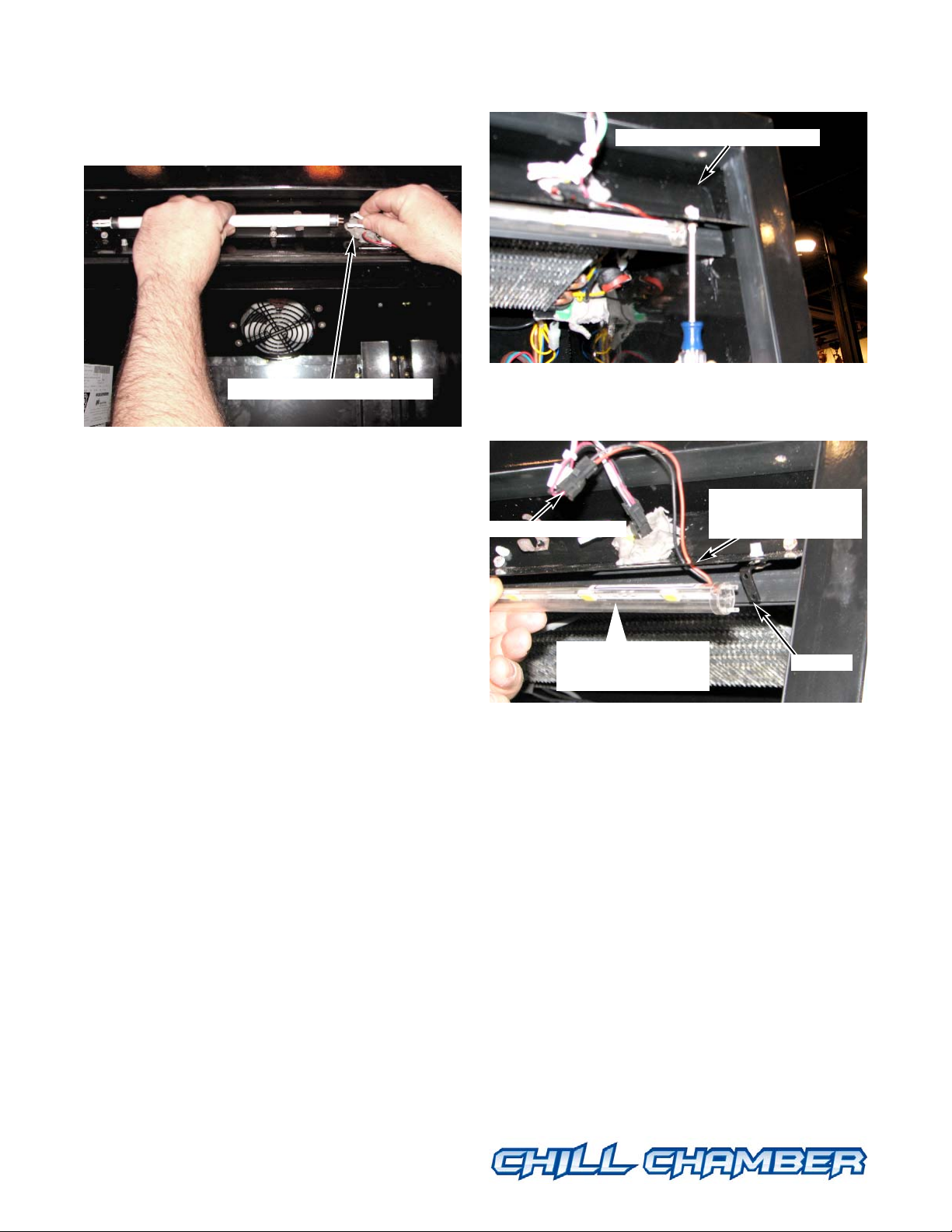
LED (Interior Lighting)
LED light tube must be replaced by a light
tube of the same size dimension and wattage as
the original. Always unplug unit before
replacing LED light strip. Restocked beer
may freeze.
1. Follow steps 1 through 7 of Fluorescent
Lamp Replacement.
2. Disconnect the LED connector.
3. With a screwdriver, loosen, but do not
remove, the LED lighting bracket from one
side only.
4. Rotate loosened lighting bracket and remove
LED light tube.
5. Replace by positioning the LED light tube
with electrical wires to the right-hand side
closest to slot. Do not wrap wires around the
LED light tube. Route the electrical wires
through the slot before re-connecting.
6. Reassemble in reverse order.
7. Plug the unit in. Turn on light switch.
8. Allow the unit to run for at least
30 minutes before stocking with fresh product.
Two individual connectors
LED lighting bracket.
LED connector
Bracket
Route electrical cord
through here
Replacement LED tube
must be at same angle
Page 16

©2007 HUSSMANN CORPORATION • BRIDGETON, MO 63044-2483 U.S.A.
U.S. & CANADA 1-800-504-4828 • WWW.CHILLCHAMBER.HUSSMANN.COM
14
P/N 31033596_B
01 June 2007
MAXI-140
OPERATING TIPS
• The unit must be allowed to stand in place for
30 minutes before it is plugged in.
• Once the unit is running, the real time clock
must be set. Once fully charged, the real time
clock’s battery will keep the clock memory for
at least one week.
• In the event of power loss, the real time clock
will keep its settings for at least one week once
the battery is fully charged. The real time clock
battery is rechargeable.
• The unit should run for 30 minutes empty
and must be within 2 degrees of 22 °F before
any product is loaded inside.
• The unit must go into defrost mode twice a
day to maintain optimal performance. During
defrost, the temperature display may move up
2 or 3°F (1 to 1.5°C). Avoid opening the door
during the defrost cycle.
• If the unit is placed in a location that is not
air conditioned or has high ambient humidity,
additional defrost cycles may be required to
prevent the rear refrigeration coil from
blocking with ice.
• Very frequent door openings will eventually
have an impact on product temperature and
cause it to rise. Avoid holding the door open
while deciding on product selection, counting
inventory, etc.
• The large blue LED display above the door
simulates the average temperature of the beer in
the cooler, not the air temperature in the unit.
Therefore, the display temperature will change
slowly as the unit cools down or warms up.
• Unplug the unit before cleaning. Clean the
unit frequently to minimize odors and to maintain operating efficiency.
• Do not add warm product.
• Restocked product may freeze.
• Never place product on the bottom of unit.
• Place the lower removable shelf flush against
the back to maintain proper air flow and
product temperature.
• The unit must remain upright at all times.
Do not tilt more than 30 degrees from vertical
at any time.
• The light switch is located on the top right
side of the interior back wall.
• Maintain air flow around the unit at all times.
To obtain warranty information
or other support, contact your
Hussmann representative
1-800-504-4828.
Please include the model and
serial number of the product.
Or go to
http://chillchamber.hussmann.com/
serv/warranty.htm
http://chillchamber.hussmann.com/
serv/ChillChamberWarranty.pdf
Page 17

TROUBLESHOOTING
The following chart identifies most common
problems, their causes, and suggested solutions.
©2007 HUSSMANN CORPORATION • BRIDGETON, MO 63044-2483 U.S.A.
U.S. & CANADA 1-800-504-4828 • WWW.CHILLCHAMBER.HUSSMANN.COM
15
P/N 31033596_B
01 June 2007
™
MAXI-140
Problem Possible Causes Solution/Action
Does not turn on Plug is out of outlet Insert plug into outlet
Poor contact at outlet Remove and reinsert plug into outlet.
If good contact cannot be established,
contact a licensed electrician to replace the outlet.
No power Power outage OR
Circuit breaker tripped
UNPLUG UNIT until power is restored
UNPLUG UNIT until breaker is reset
Safe-NET controller settings are retained for at least five days, but a power surge can cause damage.
Low Voltage Install a voltage regulator
Unusual Noise Unit not level Reposition and level the unit
Unit contacting structure Reposition unit to provide space on all sides
Rear grille loose Fasten grille to attenuate sound
Slow to cool Dirty condenser coil Clean condenser coil
product
Poor airflow around unit Reposition unit to provide space on all sides
Evaporator blocked by ice Verify that door is sealing completely
Heavy use in high humidity -- reset Safe-NET
controller to increase frequency of defrosts
Loading with warm product The warmer the product when placed in the
Chill Chamber, the longer the time needed to
cool the product.
Temperature display Recently stocked Allow time for temperature display to catch up
not accurate with stocking -- about 30 minutes.
Condensation High relative humidity Remove moisture with soft cloth. Reduce ambient
on door humidity. Move unit to area of lower humidity.
Troubleshooting Guide
To place a service call, please phone Hussmann’s call center at 1 (800) 504 4828.
Page 18

HUSSMANN CORPORATION
Limited Warranty for Chill Chambers in the United States & Canada
This warranty is made to the original user at the original installation site and is not transferable.
BASIC WARRANTY
Hussmann Chill Chambers are warranted to be free from defect in material and workmanship under normal use and
service for twelve months. Unless otherwise indicated, this warranty is valid from the date of original installation,
not to exceed fifteen months from the date of shipment from the factory.
Except as otherwise specifically set forth, Hussmann’s obligation under this warranty shall be limited to repairing
or exchanging any part or parts, without charge, FCA factory or nearest authorized parts depot (Incoterms 2000)
during the warranty period, which is proven to the satisfaction of the warranty administration organization to be
defective. Hussmann, or its designee, reserves the right to inspect the jobsite, installation and reason for failure.
Hussmann will also pay the cost of labor to install and/or replace parts at prevailing straight-time rates and repair
times which are in accordance with industry standard repair times as administered by the warranty administration
organization.
Hussmann’s warranty covers the Chill Chamber and all its components except lamps, driers, fuses and other
maintenance type replacement parts for the applicable warranty period. Additionally, for thirty-six months from
date of installation, Hussmann warrants all sealed, multi-glass assemblies. If within the warranty period, it can be
proven to the satisfaction of Hussmann’s warranty administration organization that there is impaired visibility
through a multi-glass assembly caused by moisture between the glasses, the multi-glass assembly will be replaced
free of charge, excluding freight charges from the factory or nearest authorized parts depot. This warranty excludes
accident, misuse, or glass breakage.
For Chill Chamber motor compressors, excluding capacitors and relays, Hussmann agrees to repair or exchange, at
its option, the original compressor unit only, with a compressor of like or of similar design and capacity, if it is
shown to the satisfaction of Hussmann that the compressor is inoperative due to defects in factory workmanship or
material under normal use and service as outlined in Hussmann’s “Owner’s Manual”which is shipped inside new
Chill Chambers. Hussmann’s sole obligation under this paragraph shall be limited to five years from date of factory
shipment and applies only to the compressor shipped from the factory with the new product. After year one (1), no
labor is included to replace the compressor.
EXTENDED WARRANTY
Any warranty may be extended for an additional period (not to exceed a total 60 months in combination with the
basic warranty), but must be purchased from Hussmann and documented with a paid invoice to be valid. The
extended warranty must be purchased and paid for prior to the expiration of the basic warranty coverage. The basic
and extended warranties listed above do not include replacement or repair of controls, relays, capacitors, or overload protectors.
Hussmann Chill Chamber Warranty — Page 1 of 2 — 25 January 2007
Page 19

PATENT WARRANTY
Hussmann warrants that its products do not infringe the claims of any existing United States patent, but
Hussmann makes no warranty against infringement by reason of the use thereof either in combination with
other products or in the operation of any process or use of products other than for their intended purpose. This
warranty is subject to purchaser promptly notifying Hussmann in the event of any action for such infringement
brought against purchaser and permitting Hussmann to participate in the defense of such action. Hussmann
reserves the right to modify or replace any product alleged to constitute and infringement, or to remove such
product and refund the amount paid by purchaser therefor. This warranty is not transferable. The foregoing patent
warranty shall not apply to any product or part thereof made to purchaser’s design and as to such product or part.
Hussmann assumes no liability for patent infringement. The foregoing states the entire liability of Hussmann with
regard to patent infringement.
Any warranty repair made by Hussmann shall not extend the term of the warranty. Any warranty claim must be
made to Hussmann in writing within 45 days of the warranty repair date.
THE WARRANTIES RECITED ABOVE ARE THE ONLY WARRANTIES, EXPRESS, IMPLIED OR STATUTORY,
MADE BY HUSSMANN WITH RESPECT TO ITS PRODUCTS, INCLUDING ANY IMPLIED WARRANTY OF
MERCHANTABILITY OR FITNESS, AND HUSSMANN NEITHER ASSUMES NOR AUTHORIZES ANY PERSON
TO ASSUME FOR IT, ANY OTHER OBLIGATION OR LIABILITY IN CONNECTION WITH THE SALE OF ITS
PRODUCTS OR ANY PART THEREOF.
THIS WARRANTY SHALL NOT APPLY TO LOSS OF FOOD OR CONTENTS OF THE PRODUCTS DUE TO
FAILURE FOR ANY REASON. HUSSMANN SHALL NOT BE LIABLE:
• For any repair or replacements made without the written consent of Hussmann, or when the product is
installed or operated in a manner contrary to the printed instructions covering installation and service which
accompanied such product;
• For any damages, delays, or losses, direct, consequential, incidental or otherwise, which may arise in
connection with such product or part thereof;
• For damages during shipment or caused by fire, flood, strikes, or other circumstances beyond its control;
• When the product is subject to negligence, abuse, misuse or when the serial number of the product has been
removed, defaced, or altered;
• When the product is operated on low or improper voltages;
• When the product is put to a use other than as recommended by Hussmann;
• When operation of the product is impaired due to improper drain installation;
• For payment of refrigerant loss for any reason other than on a self-contained case.
• For costs related to shipping or handling of replacement parts;
• For periodic maintenance items such as filters, gaskets, lamps, fuses, and driers;
• Diagnostic charges;
• To defend, indemnify or hold harmless any purchaser or end-user for any claims, demands, lawsuits or actions
of any nature.
Hussmann Chill Chamber Warranty — Page 2 of 2 — 25 January 2007
Page 20

22
F
 Loading...